

Page 1
PRO SERIES OPERATIONS & MAINTENANCE MANUAL
Page 2

PRO SERIES OPERATIONS MANUAL
Daktronics Automated Rigging System
Manufacturers contact info
7200 Rawson Road
Victor, New York 14564
tel 866-486-7835 585-924-5000
fax 585-924-0545
email sales@daktronics.com
daktronics.com/rigging
Copyright © 2013 Daktronics, Inc.
ED 17171 REV 5 17 July 2013
Page 3

Page 4

TABLE OF CONTENTS
01 Safety Information 1
Warning, cautions, and notes
Electrical safety—general warning
Included safety features
Compliance with regulations
EU declaration of conformity
02 General Information 5
Motor electronic variable frequency drive
Hoist assembly
Pro Series Controller (VAC)
Specications
USA VAC based models and applications
VAC—Single purchase
VAC—Double purchase
European VAC based models and applications
VAC—Single purchase
VAC—Double purchase
Dimensions of a standard unit
03 Theory of Operation 9
04 Administration 11
Password
Add user
Remove user
E-stops
Deadman
05 Manual 19
Motor selection
Motor info
Hoist info screen
Digital I/O screen
Speed
Set speed numerically
Icon selection
Up/Down
Batten position indicator
Upper target
TABLE OF CONTENTS i
Page 5

Current position
Alternate target
Lower target
Set/clear targets
Clear target
Setting targets
Move to postion
Auto up/down
Curtain control
Open target
Current position
Alternate target
Close target
Auto open/close
06 Grouping 29
Create group
Name
Modify group
Modify menu
Edit group
Trim motor
Joystick control
Rename group
Delete group
07 Cueing 35
Vocabulary
Load cue sheet
Delete cue sheet
Create cue sheet
Name
Set cue 00.00
Add Cue sheet
Number
Title
Motor/group
Target
Time/speed
More Actions
Create action
Delete action
Modify action
More cues
Delete cues
Modify cues
Run cues
i-Batten
Hide/show alert
Alert box functions
Clear fault
Bypass
Disable
ii
PRO SERIES OPERATIONS MANUAL
Page 6

08 Presets 53
Create preset
Name preset
Create
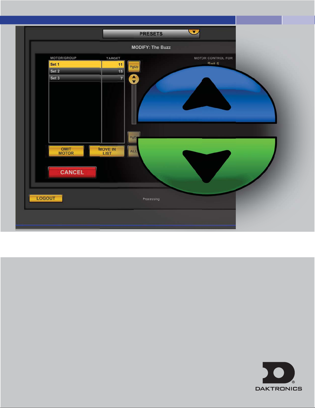
Order controls
Omit motor
Move in list
All
Target controls
Up/down
Keypad
UPR/LWR
Joystick
Delete preset
Modify preset
Modify screen
Run preset
Conrmpreset
Run screen
Pause screen
09 Setup 63
Motor selection
Batten setup
Restore factory setting
Bypass i-Batten safety
Conrm
Curtain setup
Rename
Speed
Set speed numerically
Up/down
Batten position indicator
Upper limit
Current position
Lower limit
Set/clear limits
Set upper/lower limits
Clear upper/lower limits
Move to position
Auto up/down
Icon selection
Icon management
Add category
Add icons
Delete icons
Category management
Edit category
Delete category
Curtain control
TABLE OF CONTENTS
iii
Page 7

Open target
Current position
Alternate target
Close target
10 Motor Restrictions 79
Disable motors
Enable motors
Order motors
11 E-Stop & Deadman Recognition 83
E-Stop display
Deadman display
12 View 87
View display
Numerical information
Individual display
Hoist info panel
Digital I/O panel
13 Troubleshooting 91
14 Warranty 93
15 Maintenance 95
Periodic Inspections
Recommended Supplies
System Maintenance
16 Cue Sheets 105
iv
Page 8
01 SAFETY INFORMATION
Warnings, cautions and notes
All Warning notes contained in this manual indicate information that may endanger personnel.
WARNING
The Daktronics rigging system is designed to raise and lower theatrical equipment under the rated hoist capacity
ONLY. This system is NOT designed to lift or lower personnel, and should never be used for that purpose.
Only trained and authorized personnel should be permitted to operate the Daktronics system. The unauthorized use,
alteration, or use for purposes other than those for which it was designed may cause injury to persons, damage to
the equipment, or create conditions which could lead to fatalities. All proper safety considerations must be observed.
While operating the Daktronics rigging system, a spotter must be used in conjunction with the user at all times. The spotter
must have a clear view of all moving elements while maintaining contact with the user. If an unsafe situation occurs, the
spotter must immediately signal the user to halt all movements until the environment is cleared of any person or obstruction.
All installation and maintenance involving the Daktronics drive unit itself or the main electrical control cabinets will
require trained personnel. Simple daily maintenance activities such as cleaning of the touchscreen and the VAC
workstation may be carried out by the operators, and in most cases will be all that is needed once installed.
Electrical Safety—General Warning
WARNING
Before working on any of the Vortek hoists, the main electrical disconnect must be
turned off and locked out according to OSHA regulations 29 CFR 1910.147.
The voltages used in the motor drive and master control panels can cause severe electrical
shock and/or burns. Extreme care is necessary at all times when working with the motor
drives. Only authorized personnel should carry out any installation, commissioning, or
maintenance of the electrical systems. All drive systems have been tuned at the factory
and will not require any additional alteration or adjustment by the owner’s personnel
unless specifically authorized by a Daktronics representative.
SAFETY INFORMATION
SAFETY INFORMATION
1
Page 9

Included Safety Features
i-Batten with Over-load and Under-load Protection
The i-Batten feature allows the authorized operator to preset sensitivity on the maximum and minimum
loads a specific Vortek hoist will encounter. If the system detects a load outside the set range, indicating
a possible problem, the unit will automatically stop all motion. It is strongly recommended that this feature
be used in order to prevent any injury to personnel or damage to equipment.
Emergency Stop
A red Emergency Stop mushroom head push button is located on each VAC control station. Pushing
the button will disable all motor drives connected through the specific VAC, and set all motor brakes.
This will stop all motion of the attached loads on each Vortek hoist immediately, and inhibit further
movement until reset.
The Emergency Stops should ONLY be used for real emergencies or when required to reset a motor fault
if indicated on the VAC touchscreen.
Vortek Back-Up brake
This secondary mechanical braking system is designed to hold the rated load in the improbable case of
a failure of the primary motor brake or gearbox. This system acts independently of any electrical inputs
on the system.
Compliance with Regulations
The Daktronics system complies with the relevant European directives required for the CE mark, including:
98/37/EC: Machinery Directive
73/23/EEC: Low Voltage Directive
89/336/EEC: Electromagnetic Compatibility
Independent reviews/tests in support of above compliance
EN55022 Class A Radiated and Conducted Emissions
EN61000-4-2 Electrostatic Discharge
EN61000-4-6 Conducted Susceptibility
EN60950, 60204 Safety Review
Airborne noise emissions
Continuous A-weighted sound pressure levels at distances 40 feet from the Vortek hoist module,
a typical distance for the operator VAC control unit to be located, do not exceed 70 decibels.
2
Page 10

EU DECLARATION OF CONFORMITY
Manufacturer's name and address:
Daktronics, 7200 Rawson Road
Victor, N.Y. 14564 USA
We declare under sole responsibility that the product:
Product Name:
Daktronics Automated Theater Rigging system
Product Description:
Automated Hoisting Equipment for theatrical venues
Product type/model:
Single Purchase: V_-12180, V_-1740, V_-14120, V_-2020, V_-0820, H_-22230, H_-4020,
EV_-0509, EV_-0607, EV_-0702, EV_-0901, EV_-0301, EH_-1012, EH_-1801
Double Purchase: V_-12180-2, V_-1740-2, V_-14120-2, V_-2020-2, V_-0820-2, H_-22230-2, H_-4020-2,
EV_-0509-2, EV_-0607-2, EV_-0702-2, EV_-0901-2, EV_-0301-2, EH_-1012-2, EH_-1801-2
*To reference the model list of pre-2009 hoist nomenclature, see Troubleshooting on p. 91.
Conforms to the following standard(s) :
EN 60204-1 Safety of Machinery/ Electrical Equipment for Machinery
EN 60950 (ITE) Information Technology Equipment
EN 55022 Class A Product Specific Emissions
EN 61000-4-2 Electrostatic Discharge
EN 61000-4-6 Conducted RF Susceptibility
Following the provisions of the EU Machinery Directive 98/37/EC, EU Low Voltage Directive
73/23/EEC, and EU EMC Directive 89/336/EEC.
SAFETY INFORMATION
3
Page 11

4
Page 12
02 GENERAL INFORMATION
WARNING
The Daktronics hoist system is an automated rigging system meaning that the load is not counter-weighted. Each
hoist can lift loads only up to the design capacity. Overloading will result in electrical overload protection shut
down of the hoist and possible damage to rigging components.
Each hoist system consists of an integral electric motor driven reducer, directly coupled to a cable drum, which
winds steel cables (wire ropes) leading over sheaves installed within the hoist assembly and along the structural
steel of the building. The cables support battens for attaching the load. The battens can be lowered to within the
specified trim above the stage floor to allow attachment of loads.
The Daktronics hoist system consists of three basic parts.
Motor electronic variable frequency drive
The Electronic Variable Frequency Drive and dynamic braking resistor for each motor is located in each Vortek
motorized hoist. A local control panel is located on each hoist for programming and diagnostics by factory
personnel. There is a reset-able circuit breaker located at each power point on the HV wireway. The rated
twist-locking plug on each unit acts as the main high voltage disconnect along with its corresponding CB.
The Vortek batten hoists are not designed to raise and lower people.
These hoists should NEVER be used for this purpose.
Hoist assembly (cable drum, load brake, limit switches and frame)
The Vortek hoist assemblies are mounted on the rigging steel at the top of the stage house. The gearmotor, helically
grooved cable drum, support bearing and frame structure are all factory assembled and tested. Maximum upper
height and minimum lower height are set by limit switches which are adjusted by factory-trained personnel during
installation and commissioning of the system. A position encoder is located at the brake end of each hoist motor,
attached directly to the motor shaft. Each hoist assembly is also equipped with a LOAD BRAKE, a unique safety
feature provided exclusively by Daktronics. This unit is designed to engage automatically when the load is being
lowered. This greatly reduces any possibility of a loaded batten to descend uncontrolled.
GENERAL INFORMATION
5
Page 13
Pro Series controller
Control of all hoists is possible from the Daktronics VAC console. The hoists can be controlled individually, and
operated at various speeds. Please see the Controls Operating portion of this manual for the operating procedures.
WARNING
If it is necessary to operate a hoist from a location where the operator's view of the moving
load is obstructed, a second person must be used to observe the load and communicate to
the operator.
Specifications
WARNING
THE FOLLOWING MODELS ARE VARIABLE SPEED AND DESIGNATED TO BE CONTROLLED THROUGH
THE VORTEK AUTOMATION CENTER (VAC
The Vortek hoist must only be used with a maximum load equal to the capacity stated for your
model below. Overloading the system may result in serious injury or an inoperable system.
®
). THE VAC IS A STAND ALONE AUTOMATION SYSTEM.
USA VAC® based models and applications
VAC - Single Purchase
MODEL NUMBER LOAD LBS (kg) SPEED FT/MIN (M/SEC)
V_-0820 0 - 800 (362) 0 - 20 (.1)
V_-12180 0 - 1200 (540) 0 - 180 (0.914)
V_-14120 0 - 1400 (635) 0 - 120 (.6)
V_-1740 0 - 1750 (790) 0 - 40 (0.203
V_-2020 0 - 2000 (900) 0 - 20 (0.101)
H_-22230 0 - 2200 (1000) 0 - 234 (1.2)
H_-4020 0 - 4000 (1814) 0 - 20 (.1)
VAC - Double Purchase
MODEL NUMBER LOAD LBS (kg) SPEED FT/MIN (M/SEC)
V_-0820 0 - 1600 (725) 0 - 10 (.05)
V_-12180-2 0 - 2400 (1080) 0 - 90 (0.457)
V_-14120 0 - 2800 (1270) 0 - 60 (.3)
V_-1740-2 0 - 3500 (1580) 0 - 20 (0.101)
V_-2020-2 0 - 4000 (1800) 0 - 10 (0.050)
H_-22230 0 - 4400 (2000) 0 - 117 (.6)
H_-4020 0 - 8000 (3628) 0 - 10 (.05)
Maximum travel distance is 65' (19.8 m) for Single Purchase Units, 32.5' (9.9 m) for Double Purchase Units.
6
Page 14
European VAC® based models and applications
VAC - Single Purchase
MODEL NUMBER LOAD kg SPEED M/SEC
EV_-0301 360 0.10
EV_-0509 500 0.9
EV_-0607 630 0.7
EV_-0702 790 0.2
EV_-0901 910 0.1
EH_-1012 1000 102
EH_-1801 1810 0.1
VAC - Double Purchase
MODEL NUMBER LOAD kg SPEED M/SEC
EV_-0301-2 720 0.05
EV_-0509-2 1100 0.45
EV_-0607-2 1260 0.35
EV_-0702-2 1580 0.01
EV_-0901-2 1820 0.05
EH_-1012-2 2000 0.06
EH_-1801-2 3620 0.05
Maximum travel distance is 65' (19.8 m) for Single Purchase Units, 32.5' (9.9 m) for Double Purchase Units.
Dimensions of Standard Unit
• Average weight of self-contained hoist module is 600 lb (272 kg)
• Height = 19.35" (49.15 cm)
• Length = 12' 9" (3.9 m)
• Width = 9" (22.9 cm) -- 6" (15.2 cm) centers can be achieved by positioning self-containing
hoist modules on opposite or opposing sides of the stage (stage right and stage left)
GENERAL INFORMATION
7
Page 15

8
Page 16

03 THEORY OF OPERATION
Each Vortek hoist is connected to the main high voltage power buss through a safety twist-locking plug. This plug
brings in the main 3-phase power that is connected to the motor drive and motor brake located in each hoist
assembly. Also connected to each Vortek hoist assembly through safety locking connectors are 24 V DC power,
E-Stop circuit, and a computer network cable.
The motor drive controls all movements of the hoist. Each drive on each hoist contains programming to identify
it to the network. This programming also includes but is not limited to maximum speed, acceleration, gear ratios
and soft limits. Each motor drive monitors an incremental encoder, limit switches, i-Batten™ safety feature and
emergency stop status. The incremental encoder is used for position control. The limit switches are used for
maximum up and down travel. i-Batten safety feature is used for the detection of both an underload or overload
condition. The emergency stop status is used to detect the operation of the emergency stop system.
Monitoring of each hoist is done over the network using a master drive. The master drive is located in the master
drive cabinet typically at stage level. Included in the master drive cabinet are the master drive and the network
hubs. A 24 V DC power supply that powers the network hubs and the E-Stop circuit is also located in the master
drive cabinet.
®
The main Daktronics Pro Series controller (VAC) is comprised of a Pentium
joysticks and E-Stop button. The VAC computer runs a proprietary Windows® based application that allows the
operator to perform manual and programmable functions to any or all of the hoists connected to the system. The
VAC is connected to the master drive and motor drives through an ArcNet™ based network operating at 2.5
Mbaud. During operation of the VAC, data is transmitted from the VAC computer through the network system to the
master drive and distributed to the appropriate hoist drive. Likewise, data is received from each hoist drive through
the master drive and to the VAC computer for display by the VAC operating software. The 24-volt dc E-Stop circuit
is also connected to the E-Stop button located on the front of the VAC.
class computer, touch screen, keyboard,
THEORY OF OPERATION
9
Page 17

10
Page 18
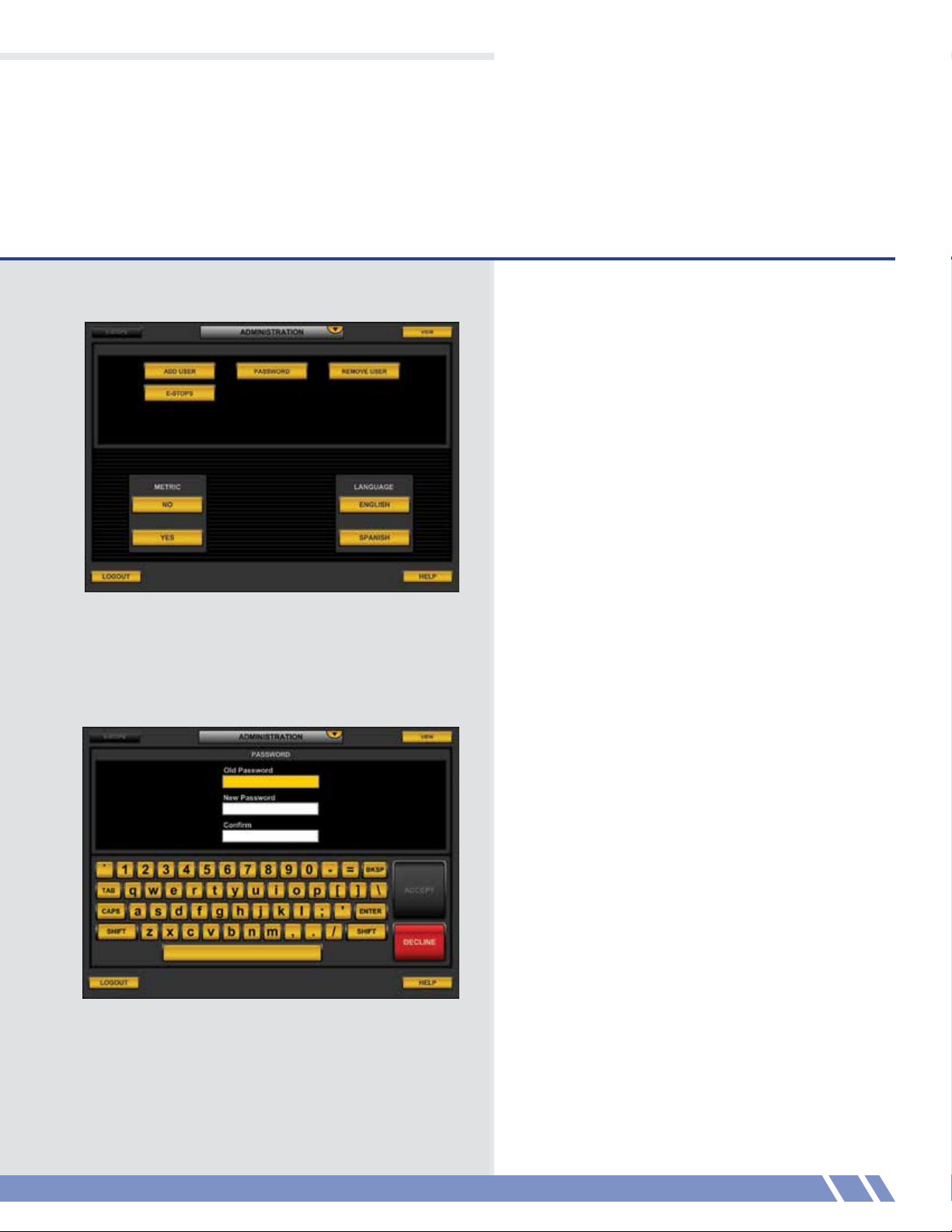
Figure 4.1: Administration screen
04 ADMINISTRATION
The administration module (Figure 4.1) allows the
user to change the system preferences according
to their security level.
An operator may change their password.
An administrator may add users, change their
password, or remove users at administrator
level and below.
The screen on the top shows the operator level
screen, while the screen on the bottom shows
the administrator level screen.
On-screen assistance can always be found by
touching HELP in the lower right corner.
Figure 4.2: Password screen
Password
Touch PASSWORD from the main menu to edit
your password for the system.
Before your password can be changed, you must
first enter your old password so the system can
verify your identity.
Select the next field to enter by touching the field
you wish to enter.
Enter your new password in the New Password
field (Figure 4.2) and the Confirm field.
When the Old Password is correct and the New
Password fields contain the same value, the ACCEPT
button will light. Touch ACCEPT to confirm the
change, or touch DECLINE to return to the main
menu without changing the password.
ADMINISTRATION
11
Page 19
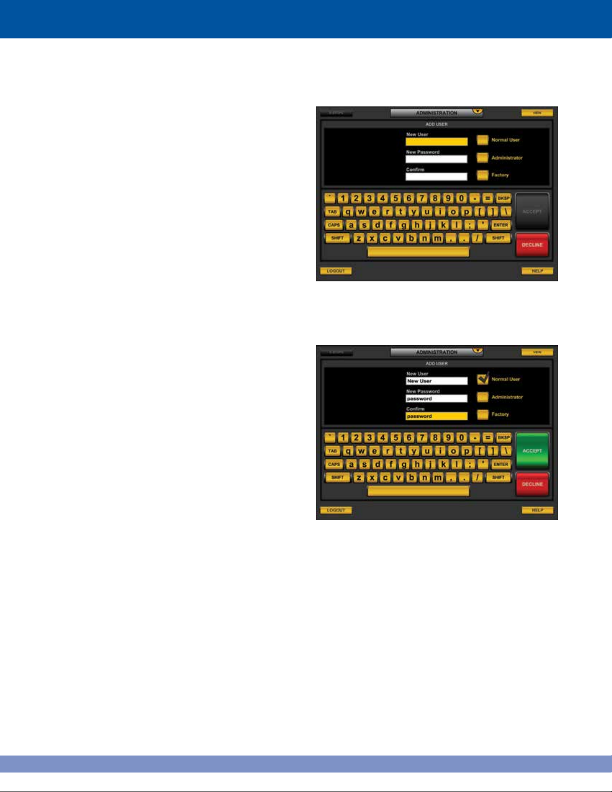
Add user
From the main menu, Administrators may touch
ADD USER to insert profiles of new users into
the system. The New User screen (Figure 4.3)
will display.
A profile consists of the new user’s name, password
and user type (either Normal User, Administrator,
or Factory).
A complete profile (Figure 4.4) of the new user must
be entered before the Accept button will activate.
Touch ACCEPT to confirm the addition of the user.
Figure 4.3: New User screen
12
Figure 4.4: New User screen with a complete profile filled in.
Page 20
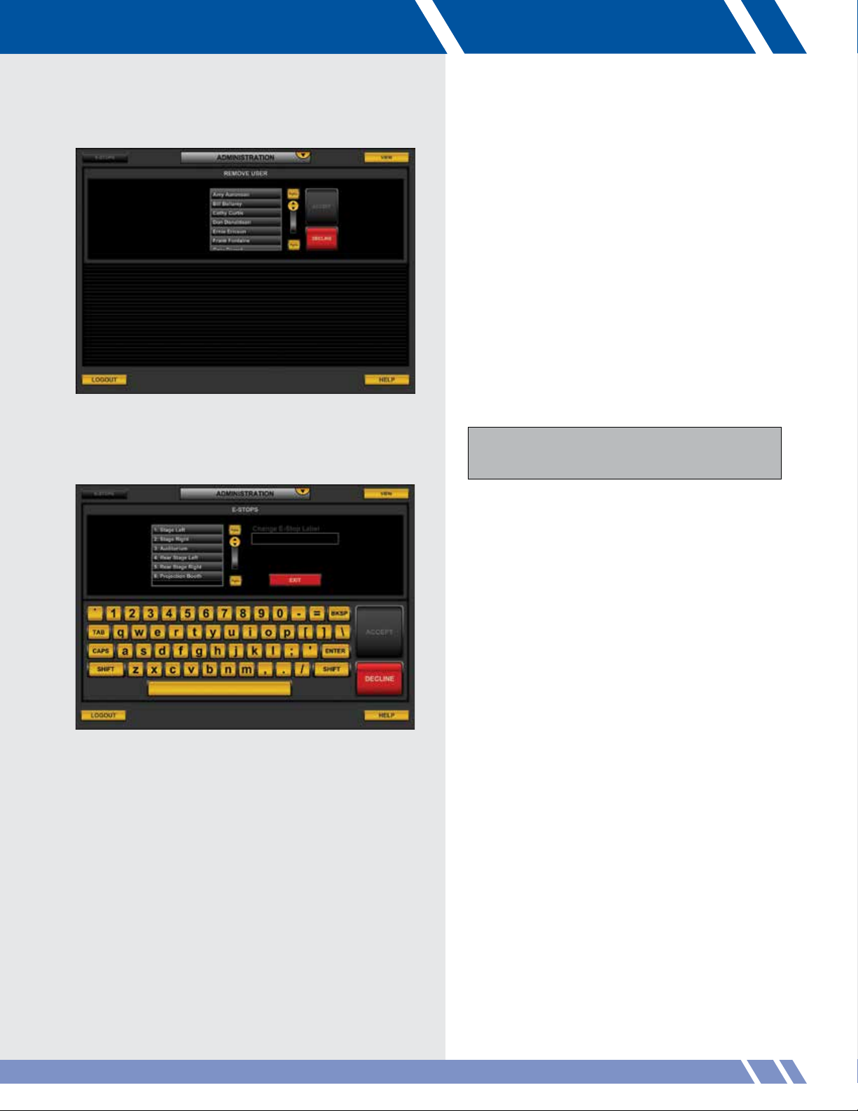
Figure 4.5: Remove User screen
Remove user
From the main menu, administrators may touch
REMOVE USER to delete profiles of users out of
the system. The Remove User screen (Figure 4.5)
will display.
Select a user by touching their name. After selection
the Accept button activates.
Touch ACCEPT to confirm the removal of the user
and return to the main menu.
Administrators may only delete Administrators and
Operator level users. Administrators can not delete
Factory level users.
Figure 4.6: E-Stops screen awaiting selection.
E-Stops
From the main menu, administrators may touch
E-STOPS to edit the names of multiple E-Stops for
the system. The reason to do this is to specify the
location of the activated E-Stop.
Select an E-Stop by touching its name.
13ADMINISTRATION
Page 21
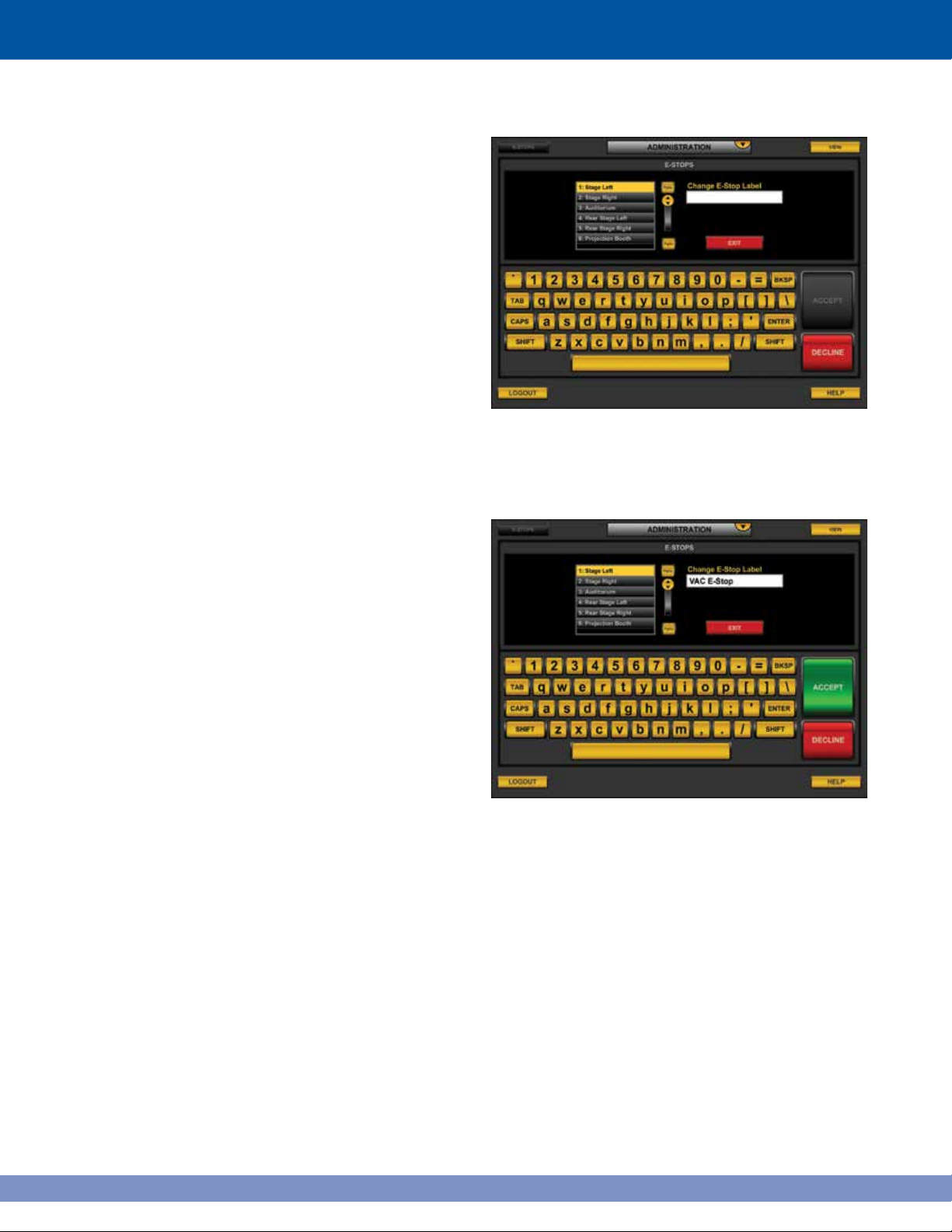
After selection the Change E-Stop Label field activates.
Type a new name for the E-Stop and touch ACCEPT
to confirm the new name.
Figure 4.7: E-Stops screen awaiting the new name
14
Figure 4.8: E-Stops screen.
Page 22
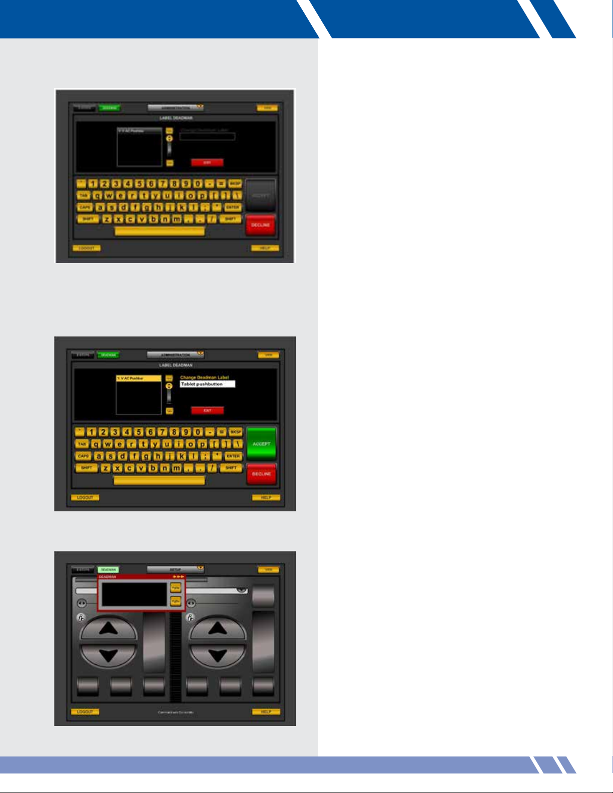
Figure 4.9 Label Deadman screen
Deadman
From the Administration module, (Figure 4.9)
administrators may touch LABEL DEADMAN to
edit the names of one or more Deadman switches
for the system (Optional). This will help identify the
Deadman switch location where multiple Deadman
switches are required.
Select a Deadman switch to edit
After selecting a Deadman switch to edit, the Change
Deadman Label field activates. Type a new name for
the Deadman switch and touch ACCEPT to confirm
the new name (Figure 4.10).
Figure 4.10: Change Deadman Label field
Figure 4.11: Deadman open window
Upon pressing the DEADMAN button, a window will
open (Figure 4.11).
ADMINISTRATION 15
Page 23
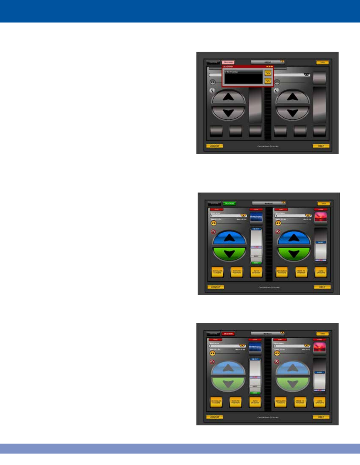
This window will list the name of any Deadman
switch that is not depressed (Figure 4.12).
The Deadman button will change from red to green
when the DEADMAN switch is pressed, allowing
movement (Figure 4.13).
Figure 4.12: Deadman switches not tripped
All hoist movement will be inhibited and each
move initiating button will be grayed out and
unusable until the Deadman switch(s) is
depressed (Figure 4.14).
16
Figure 4.13: Green button allows movement
Figure 4.14: Hoist movement inhibited
Page 24
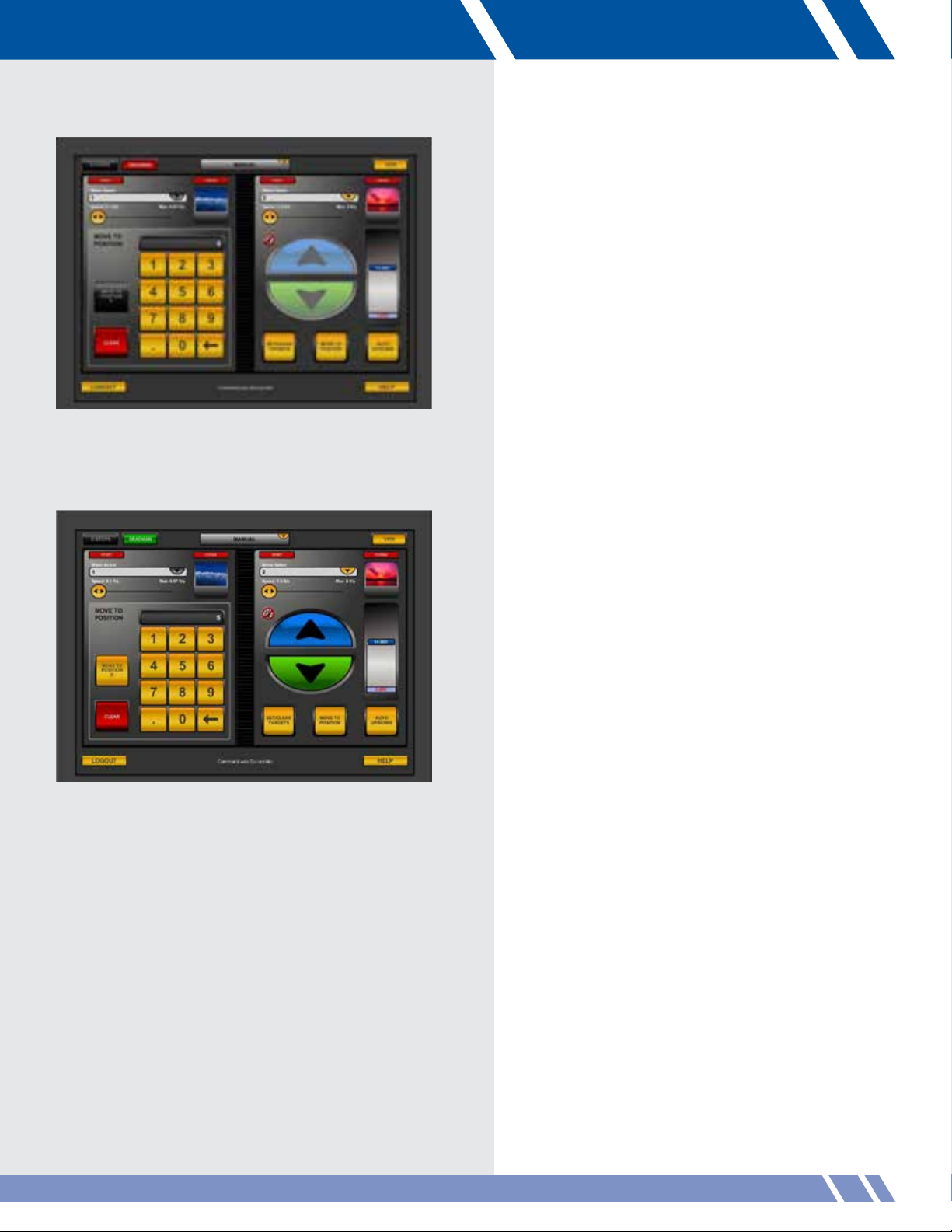
Figure 4.15: Move to Position control disabled
Move to Position control is also disabled while
the Deadman switch is not pressed (Figure
4.15)
.
When the Deadman switch is depressed, control
functionality will be restored, and grayed out buttons
will once again be available. This function applies to
all modules when the Deadman feature is enabled.
(Figure 4.16).
Figure 4.16: Deadman functionality restored
17ADMINISTRATION
Page 25

18
Page 26
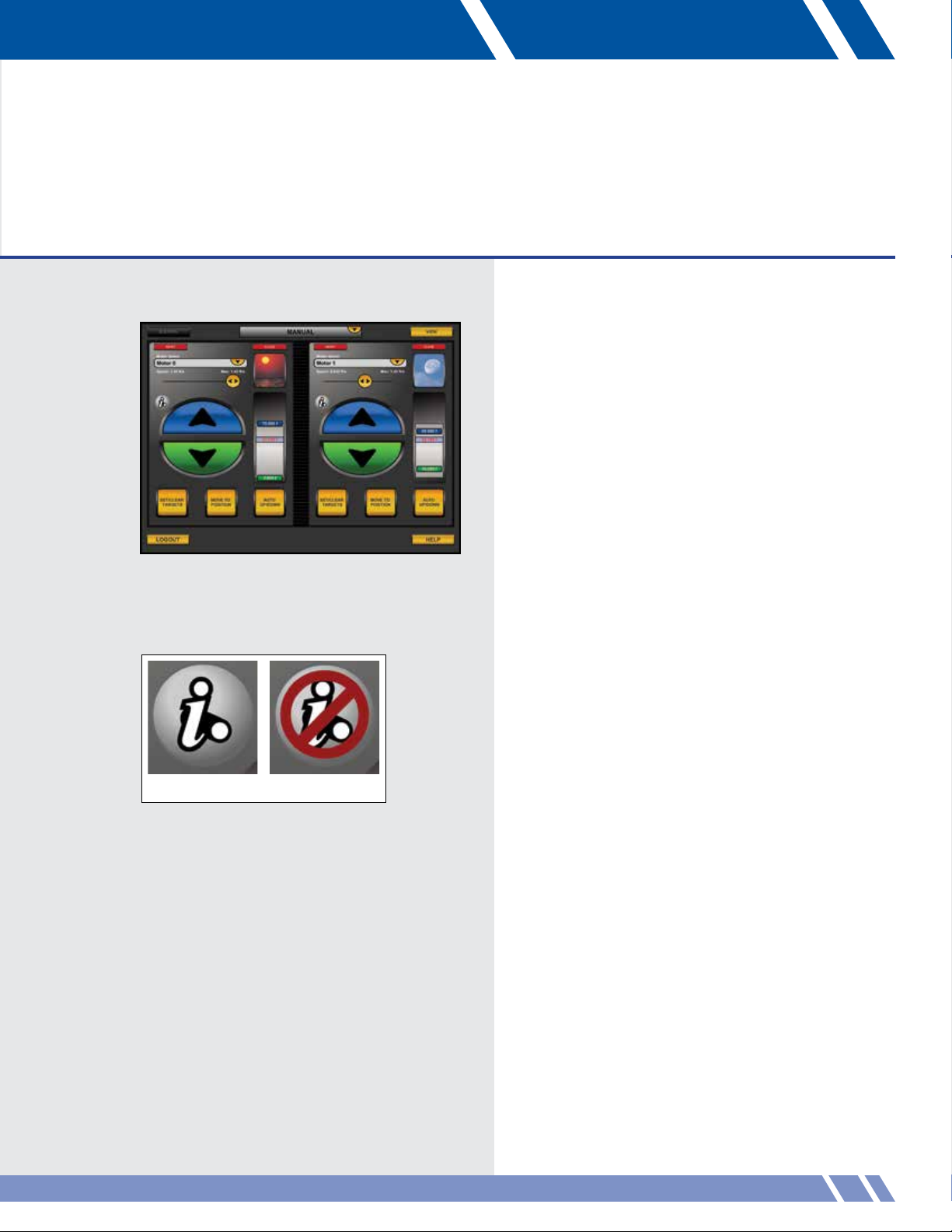
Figure 5.1: Manual screen
05 MANUAL
The Manual module (Figure 5.1) has two controllers,
each of which controls a motor, group or curtain.
After selecting which element to control, its speed,
position, targets or icon may be changed.
Additionally, the controllers display the state of the
i-Batten safety feature. If a weight change for the
batten is detected, the Vortek will stop the motor from
moving until the batten weight returns to normal.
If the safety feature is disabled for a motor or group,
the controller will display a red slash over the i-Batten
logo (see Figure 5.2).
On-screen assistance can always be found by
touching HELP in the lower right corner.
Enabled Disabled
Figure 5.2: i-Batten status
19MANUAL
Page 27
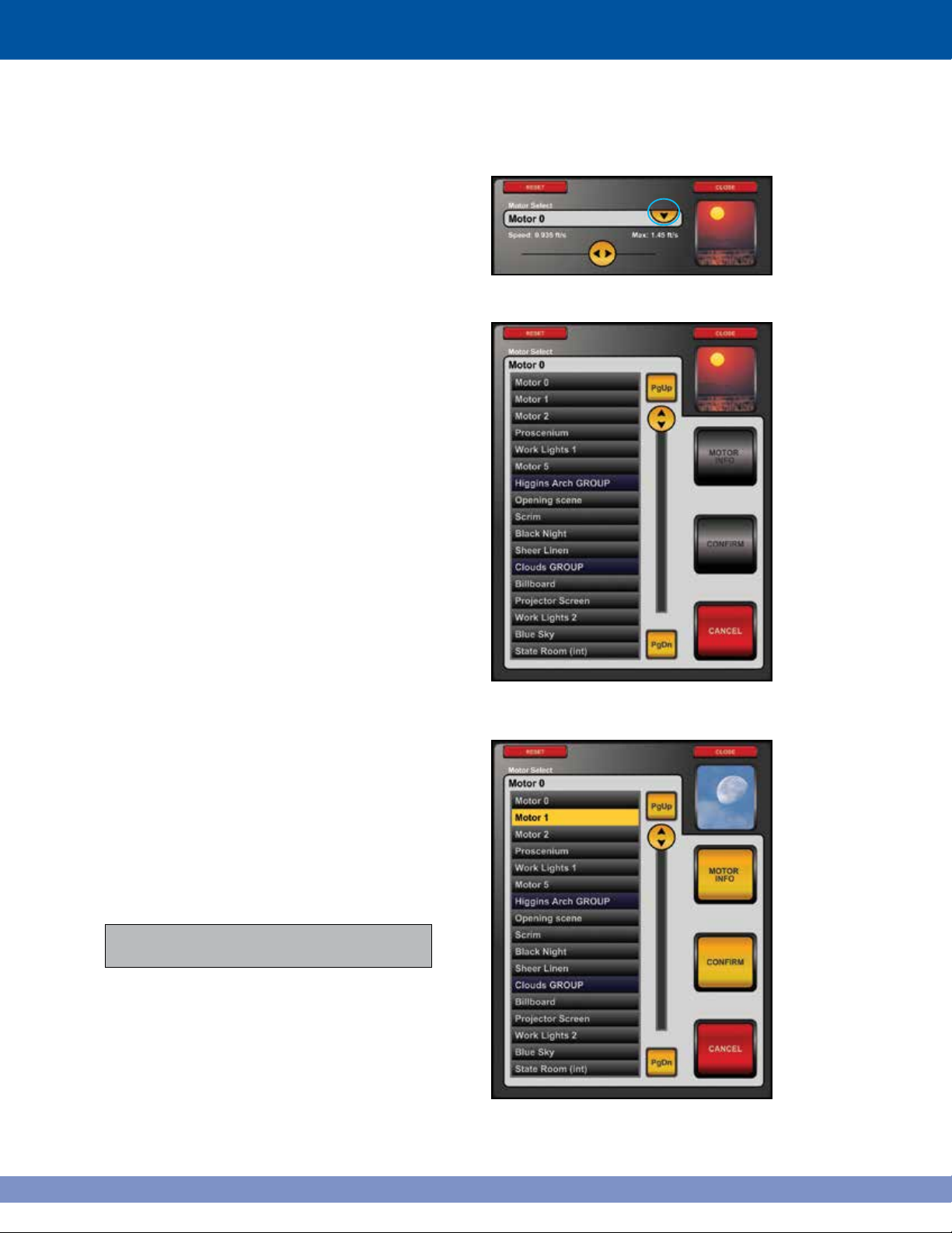
Motor selection
Select a motor by touching the yellow drop
down button at the top of the menu as shown
in Figure 5.3.
The dropdown menu expands to show a list of all
available motors, with grouped motors shown in
blue (Figure 5.4).
Move through the list by using the:
• Slider
• PgUp
• PgDn
Figure 5.3: Motor Select button
Touch the name of the desired motor or group to
select it. It will highlight and both MOTOR INFO
and CONFIRM will activate (Figure 5.5).
Touch CONFIRM to verify the selection. If there’s a
need to find out more detailed information about
the selected motor, touch MOTOR INFO.
Before touching CONFIRM, change the
selection by touching a different motor name.
Figure 5.4: Motor Select screen
Figure 5.5: Motor selected
20
Page 28
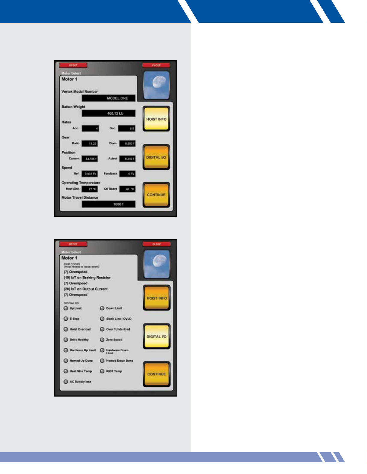
MOTOR INFO
When the MOTOR INFO button is touched, the
Hoist Info screen is displayed (Figure 5.6).
Hoist Info screen
This screen has details about the
• Batten Weight
• Acceleration Rates
• Gear Ratio and Diameter
• Batten Position
• Motor Speed
• Operating Temperature
• Travel Distance
Touch the DIGITAL I/O button to display
the Digital I/O screen (Figure 5.7) or touch
CONTINUE to return to the normal display.
Figure 5.6: Hoist Info screen
Figure 5.7: Digital I/O screen
Digital I/O screen
This screen displays:
• The last five trip codes
• Whether the motor is at the
Upper / Lower Limit
• Whether an E-Stop is engaged
• Whether an Overload or Underload
has occurred
• Whether the motor is healthy
• Whether the motor is not moving
• Whether the hardware Upper / Lower
Limit is reached
• Whether a Homed Up / Down command
has been completed
• Whether extreme operating temperatures
have been encountered.
• Whether the motor’s power has been lost
Touch the HOIST INFO button to display the
Hoist Info screen or touch CONTINUE to
return to the normal display.
MANUAL 21
Page 29
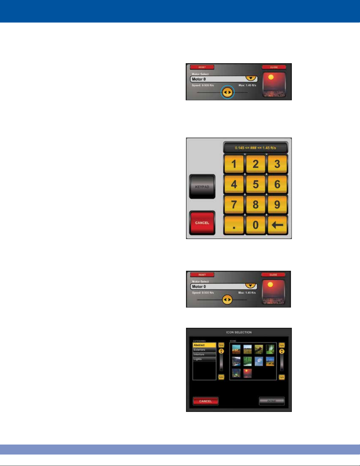
SPEED
The speed button is located under the Motor Select
dropdown menu (Figure 5.8). To change the speed,
touch and hold down the speed button. Slide it to the
right to increase the speed of the selected motor, or
left to decrease the speed.
Above the button, the current speed is shown on the
left, while the maximum speed of the selected motor
is shown on the right.
Set Speed Numerically
Touch the speed button twice quickly (double-click)
to adjust the speed with greater accuracy,
The controller will display a keypad for manual entry
(Figure 5.9). Enter the new speed value and touch
KEYPAD to confirm the entered value.
Figure 5.8:
Speed button
Icon Selection
The button for icon selection is located to the right of
Motor Select (Figure 5.10). The icon for the selected
motor appears here.
To change the icon, double-click the icon to display
the Icon Selection panel (Figure 5.11).
Select a category by touching its name in the
category list. The different icons available will
display in the box on the right. Use the scroll bar
to navigate through the icons. Choose an icon by
touching it.
Touch DONE to confirm the selection, or CANCEL
to leave the function without changing the icon.
Figure 5.9: Enter speed numerically
Figure 5.10: Icon Selection button
22
Figure 5.11: Icon Selection
Page 30
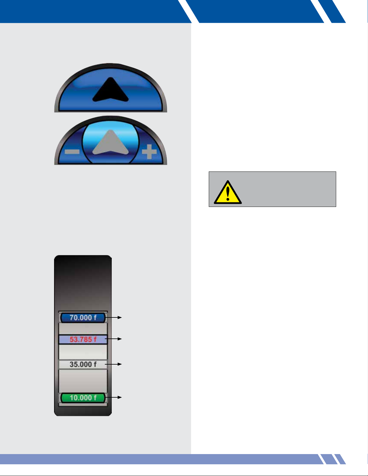
UP / DOWN
These buttons raise or lower the batten. They
are colored blue for up and green for down.
To move the motor, touch and hold an arrow
key. When pressed, they divide into three areas
(Figure 5.12).
Touch the MINUS (-) to decrease the
speed, or to PLUS (+) to increase it while the
motor is moving. The motor will stop moving
when the button is no longer touched or the
motor has reached its pre-set target position.
Figure 5.12: Up arrow depressed
Upper target
Current position
Alternate target
WARNING
If any problems arise during any hoist
motions, depress the Emergency
Stop button located below the
monitor immediately and all hoist
movements will stop.
BATTEN POSITION INDICATOR
This displays the batten position visually and
numerically relative to its upper and lower target
height. The batten upper and lower target values
along with alternate targets (if any exist) are also
displayed (Figure 5.13).
Upper target
This dark blue button shows the value for the
upper target.
Current position
This light blue bar shows the position of the
batten in relation to the targets. As the batten
moves, this display will move as well.
Figure 5.13: Batten indicator
Lower target
Alternate target
This gray box is another target position.
The VAC allows three of these per motor.
Lower target
This green button shows the value for the
lower target.
MANUAL
23
Page 31

SET / CLEAR TARGETS
To set or change the targets, touch SET /
CLEAR TARGETS (Figure 5.14). The screen will
display the Set/Clear Targets panel (Figure 5.15).
Clear Target
Touch the desired CLEAR button to clear a target
(Figure 5.15). The CLEAR button touched will
change to read CONFIRM. Touch this button to confirm
clearing the target.
Note: Clearing an upper (or lower) target resets
its value to the upper (or lower) limit.
Setting Targets
Touch SET TARGETS. The Set Targets panel displays
(Figure 5.16). Select which target to set from the
dropdown menu
(Figure 5.16a).
Enter a new value
for the target
with the keypad.
Touch KEYPAD to
confirm the new
value.
Alternately, touch
CURRENT to
use the current
position of the
batten as the target.
After entering a new target or using the
current batten position, touch CONTINUE
to return to the main screen.
Figure 5-16a: Dropdown menu
Figure 5.14:
Figure 5.15: Set/Clear Targets panel
Set/Clear Targets button
A limit is the operational boundary of a motor.
A motor can not move outside its limits, which
are set by an administrator.
A target is a preset motor position that may be
set within the limits set by the administrator.
24
Figure 5.16: Set Targets panel
Page 32

Figure 5.17:
Move To Position button
MOVE TO POSITION
To move a batten to a specific height, touch
MOVE TO POSITION (Figure 5.17).
The controller will display a new panel with a
keypad (Figure 5.18). Enter the desired height using
the keypad. Set the speed for the move by using the
speed button and touch MOVE. The motor will move
to the target and stop.
While the motor is moving, the Move To Position
button will be changed to read Stop. The STOP
button will slow and halt the motor prior to
reaching its target.
Figure 5.18: Move To Position panel
Figure 5.19: Auto Up/Down button
Upper target
Alternate target
Alternate target
Alternate target
Lower target
Auto Up / Down
To move the motor to its upper,blower or alternate
targets, touch AUTO UP / DOWN (Figure 5.19).
The controller will display a new panel with
between two and five buttons (Figure 5.20):
• Upper target
• Lower target
• Alternate targets (if any)
• CANCEL (not shown)
To move to a target, set the speed using the speed
button, then touch and hold either of the target
buttons for three seconds.
When the motor begins moving, the CANCEL
button will change to STOP. Touch STOP to halt
the motor's movement.
During any hoist movements, in an emergency,
press the Emergency Stop button.
Figure 5.20: Auto Up/Down panel
MANUAL
25
Page 33

Curtain control
If the controller is set to control a curtain, the display
will look like Figure 5.21.
The Up / Down buttons will change to Open / Close
buttons (Figure 5.22). These function the same as
the Up / Down buttons.
Figure 5.21: Curtain controller
Open target
This dark blue button shows the value for the upper
target. Blue vertical line shows the curtain position
at the upper target.
Current position
This light blue bar shows the value of the curtain’s
current position. As the curtain moves, this red
curtain graphic will move as well.
Alternate target
Alternate target positions are shown with gold
vertical bars.
Close target
This green button shows the value for the lower
target. Green vertical lines show the curtain
position at the lower target.
Figure 5.22: Open arrow depressed
Open target
Current position
Close target
Figure 5.23: Curtain indicator
26
Page 34

Figure 5.24: Auto Open/Close button
Open target
Alternate target
Alternate target
Auto Open / Close
To move the motor to its upper, lower or
alternate targets, touch AUTO OPEN /
CLOSE (Figure 5.24).
The controller will display a new panel
with 2 to 5 buttons (Figure 5.25):
• Open target
• Close target
• Alternate targets (if any)
• CANCEL (not shown)
To move to a target, set the speed using the speed
button, then touch and hold either of the target
buttons for three seconds.
When the motor begins moving, the CANCEL
button will change to STOP. Touch STOP to halt
the motor's movement.
Alternate target
Close target
Figure 5.25: Auto Open / Close panel
MANUAL
27
Page 35

28
Page 36

Figure 6.1: Grouping screen
06 GROUPING
Multiple motors may be set to act in unison by
using the Grouping module (Figure 6.1). This is
useful for assuring that multiple battens holding the
same set will move together simultaneously.
Although a group is always two or more motors,
Daktronics treats them as one motor in the Manual,
Setup and Cueing modules.
On-screen assistance can always be found by
touching HELP in the lower right corner.
GROUPING
29
Page 37

CREATE GROUP
The Create function has two motor lists, the Motors
list and the Group Motors list (Figure 6.2). Move
through either list by using the scroll button, PgUp or
PgDn.
To add a motor to the group, touch its name in
the available motor list. The motor is immediately
removed from the available list and is displayed
in the group motor list.
To remove a motor from the group, touch its name
in the group motor list. The motor is immediately
removed from the group motor list and is
displayed back in the available list.
On the left is a list of the all available motors (in
alpha-betical order). A motor that is disabled or
part of another group will not appear here. On
the right is a list of all motors selected to be
grouped, which is empty at this point.
Touch CANCEL to go back to the main screen
without creating the group.
When all of the desired motors are shown in
the group motor list, touch DONE to name the
new group.
Figure 6.2: Create function.
30
Figure 6.3: Motors added to group
Page 38

Figure 6.4: Naming a new group
NAME
The group motor list is now deactivated to show
that it can not be changed at this point (Figure
6.4). The group can be changed later with the
Modify function.
Type a name for the new group using the VAC
keyboard. A group name can only be made of
letters and numbers. Typing a name activates
the DONE button.
After entering the name, touch DONE to confirm
and create the new group. The screen will change
back to the main grouping screen and then the
message Group created will display in the
status message area.
MODIFY GROUP
The Modify function displays a list of groups on
the left hand side (Figure 6.5). Select a group to
work with by touching its name. The Continue
button will activate. Touch this to begin modifying
the selected group.
Figure 6.5: Modify function
GROUPING
31
Page 39

MODIFY MENU
The selected group name appears on the left
above the editing choices (Figure 6.6).
Touch EDIT to add or remove motors from the
group, TRIM to change an individual motor
position, RENAME to change the group name
or EXIT to return to the main screen.
EDIT GROUP
A list of all available motors (in alphabetical order)
is on the left (Figure 6.7). A motor that is disabled
or part of another group will not appear here. On
the right is the list of motors in the selected group.
To add a motor to the group, touch its name in
the available motor list. The motor is immediately
removed from the available list and is displayed
in the group motor list.
To remove a motor from the group, touch its name
in the group motor list. The motor is removed from
the group motor list and is displayed back in the
available list.
Touch CANCEL to go back to the main menu
without editing the group.
Touch DONE to confirm the edits to the selected
group and return to the Modify menu.
Figure 6.6: Edit menu
Figure 6.7: Edit function
32
Page 40

Figure 6.8: Trim motor
Figure 6.9: Trim controls activated
Trim motor
To change the position of an individual batten
within a group, use the Trim function.
Select a motor to trim from the list of grouped
motors on the left (Figure 6.8).
The trimming controls activate after a motor has
been selected (Figure 6.9).
The up and down arrow buttons will move the
batten at minimum speed. Touch and hold an
arrow button to begin moving the selected motor.
The motor will stop moving when the button
is released.
Touch EXIT to return to the Edit menu.
Joystick control
The joystick provides faster trimming speed.
To control the motor with the left joystick, touch
JOYSTICK under the arrow buttons (Figure 6.9).
The button will change to read FINISHED and all
other screen controls are deactivated. The left joystick
is now activated to move the selected motor. The
motor speed increases as the joystick moves farther
from center. Push the joystick forward for the up
direction and backwards for the down direction.
When the batten is in the correct position, touch
FINISHED to activate the rest of the controls and
deactivate the joystick.
GROUPING
33
Page 41

Rename group
Type a name for the new group using the VAC
keyboard (Figure 6.10). A group name can only
be made of letters and numbers. Typing a name
activates the ACCEPT button.
Touch ACCEPT to confirm the name and return
to the Edit menu.
Touch CANCEL to return to the Edit menu without
renaming the group.
DELETE GROUP
The list of groups is on the left. Select a group
by touching its name in the list. When a group is
selected, its motors display in the group motor list
on the right (Figure 6.11). This list is only to help
select the correct group for deletion. Selecting a
group also activates the DELETE button.
To permanently remove the group, touch DELETE.
To return to the main screen with no changes,
touch CANCEL.
Figure 6.10: Rename function
34
Figure 6.11: Delete function
Page 42

Figure 7.1: Cueing screen
Cue Sheet Breakdown:
1. Cue Sheet
2. Cue Lists A,B,C (Can be new shows or segments of one show).
3. Cues (Individual cues within a Cue List)
4. Cue Actions (Individual actions within a Cue)
Each cue is made of actions, called cue actions. These cue actions move motors, set timing for cues or keep notes.
Each cue action has a:
07 CUEING
This module works with cues. Cues are commands for
the Vortek hoists to carry out. The most common cue
is to move a motor or group, but there are others as
well. A set of cues for a show is called a cue sheet.
Each cue sheet is named for the show. For example,
the set of cues for a production of Annie is called the
Annie cue sheet.
The first menu for cueing is similar to the main menus
in the Grouping and Presets module. These choices
manage cue sheets (Figure 7.1). Touch CREATE
CUE SHEET to create a new show, or touch LOAD
CUE SHEET to work with an existing one. Touch
DELETE CUE SHEET to remove a cue sheet entirely.
On-screen assistance can always be found by touching
HELP in the lower right corner.
CUE SHEET VOCABULARY
Number The cue number sets the order of the cue in the cue sheet. Lower numbered cues run before higher
•
numbered cues. The cue number must be between 0.01 and 99.99. Cue 0.00 is always the initial staring
cue programmed into a cue list.
Title The title is only for describing a cue. For example, it may say “Act II Scene 3.”
•
• Motor/Group This motor/group will be moved by the cue action.
• Target The cue target is the destination for the motor/group.
• Time/Speed The time/speed value is how much time it will take to travel or how fast the motor will travel.
• Note A description of the cue action. For example, it may say “Motor 0 to upper limit.”
• Next This describes the link between this cue action and what follows.
CUEING
35
Page 43

LOAD CUE SHEET
The list of available cue sheets is shown in the center
of the screen (Figure 7.2). Select a cue sheet by
touching its name in the list. When one is selected,
the ACCEPT button will light up.
After selecting, touch ACCEPT to confirm the
selection and load the cue sheet. To return to the
first screen without loading a show, touch CANCEL.
DELETE CUE SHEET
Select a cue by touching its name in the list (Figure
7.2). When one is selected, the DELETE button is
activated (Figure 7.3).
To permanently remove the show, touch DELETE.
To return to the main screen with no changes,
touch CANCEL.
CREATE CUE SHEET
Name
After selecting CREATE CUE SHEET from the first
menu, type a name for the new show using the Pro
Series keyboard or the virtual keyboard (Figure
7.4). A show name can only be made of letters
and numbers (25 max). Typing a name activates the
ACCEPT button.
After entering the name, touch ACCEPT to confirm it.
Touch DECLINE to go back to the first menu without
creating the new cue sheet.
Set Cue 00.00
The starting position of all the motors needs to
recorded when a new show is created. It is important
that the motors start in the correct positions because
all motor movement is based from this starting point.
The starting position for the motors is Cue 00.00.
Modify > Cue Zero screen (Figure 7.5). Touch USE
MANUAL SCREEN to adjust the motors with the
Manual Screen. On the Manual Screen page, touch
CLOSE to return to Cueing. Touch SET CUE 00.00 to
record the initial motor positions for the show.
Figure 7.2: Load Cue Sheet function
Figure 7.3: Delete cue sheet
Figure 7.4: Name cue sheet function
36
Figure 7.5: Set cue 00.00 screen
Page 44

Figure 7.6: Manual screen
If the motors are not in their correct position, touch
MANUAL SCREEN. The VAC will display the
Manual Screen (Figure 7.6). Us the controllers
on this screen to move the motors to the correct
positions. (For more information see the Manual
chapter.)
.
There are three cue sheets per show: A, B and C.
The initial screen for a new show with no existing
cues is shown (Figure 7.7). At any point the
operator may view or edit the other sheets, simply
touch the desired tab or the sheet itself.
Cue Sheet B initial screen is illustrated (Figure 7.8)
with no existing cues.
Figure 7.7: Newly cue sheet
Figure 7.8: Cue Sheet B initial screen
CUEING
37
Page 45

Cuesheet: / A / B / C /
Number Title / Motor - Group / Action Target Speed / Time Next
Show Name:
Cuesheet: / A / B / C /
Number Title / Motor - Group / Action Target Speed / Time Next
A00.00 Initial Motor Setup
A01.00 Cue 1
A01.00.0 Motor 0 UPPER 1.4 ft./sec. AND
A01.00.1 Motor 1 LOWER 15 sec. END
A02.00 Cue 2
A02.00.0 Motor 0 LOWER 1.4 ft./sec. AND
A02.00.1 Motor 3 15' 6" 12 sec. END
Show Name: Example Cuesheet
Figure 7.9 is an example of a blank cue sheet
(additional copies can be found later in this manual).
Figure 7.10. shows an example of one of the cue
lists within the cue sheet showing three cues filled in
(cues 0,1 and 2) and their associated actions (cue
1.00 three actions, cue 2.00 one action).
The very first cue (00.00) for this show is the starting
position for all the motors. The programmable cues
start with the second line.
Cue 1.00 has three cue actions: moving Motor 0,
Motor 1 and Motor 2. Each motor will move to either
their upper or lower target (see the Manual chapter
to see how to set this). Each action will move at 1.4
feet per second.
The Next column displays either AND or END. The
rule is: If there are more actions in this cue, the Next
value is AND. If there are no more actions in this
cue, the Next value is END.
Figures 7.11 and 7.12 show a fictional stage with
battens at random positions like they might be at the
start of creating a new show. The upper and lower
limits are set by the administrator.
Use the manual screen to set upper and lower targets
for the three motors in the motor list. Move the motors
to a point in between their upper and lower targets
for the starting position.
Figure 7.9: Blank cue sheet
Figure 7.10: Cue sheet for new show
C EILING
UPPER LIMIT
M2
M0
FRONT BACK
M1
LOWER LIMIT
STAGE
Figure 7.11: Battens at random positions, viewed
from stage left
C EILING
UPPER LIMIT
UPPER TARGET
FRONT BACK
Figure 7.12: Battens ready to set Cue 00.00, viewed
from stage left
M0
M1
STAGE
M2
LOWER TARGET
LOWER LIMIT
38
Page 46

Figure 7.13: Cue number screen
ADD CUE
Number
Return to Cue List A, touch ADD to begin the
process to add a new cue. The first screen allows
the operator to enter a cue number for the new cue.
Enter the cue number by touching the buttons on
the keypad (Figure 7.13). The ACCEPT button
will activate when an entry has been made.
Touch ACCEPT to confirm your entry, or touch
CANCEL to return to the main menu without
creating a cue (Figure 7.13).
Note: When the cue will be “01.00” it is not
necessary to enter the leading zero, the decimal
point or the decimal numbers.
Title
Enter the cue title by using the Daktronics
keyboard or the virtual keyboard (Figure 7.14).
The ACCEPT button will activate when an entry
has been made.
Touch ACCEPT to confirm the entry, or touch
DECLINE to return to entering the cue number.
Note: When adding a cue, the CANCEL
or DECLINE buttons will step backwards.
Figure 7.14: Enter cue title
CUEING
39
Page 47

Motor/Group
There are two kinds of cue actions: those that
command motors to move and those that do not.
To command a motor to move:
Select the Motor from the list for the first action of a
new cue (Figure 7.15). The CONFIRM button will
activate when a selection has been made. When
the motor group actions are set, touch CONFIRM to
continue.
Touch NO MOVE to command no action, or touch
CANCEL to return to entering the cue title.
Touch NO MOVE to see the options available
(Figure 7.16).
There are two No Move commands.
• A WAIT command will pause for a specified
amount of time before the next action is run.
A WAIT may be placed anywhere in a cue.
After selecting a wait, the VAC will display
a keypad to enter the amount of time to
wait before running the next action.
• A FOLLOW command can only be the last
action in a cue and tells the VAC controller to
execute the following cue immediately.
Figure 7.15: Select Motor
A WAIT command will pause for a specified
amount of time before the next action is run. If the
WAIT is in the middle of a cue, it begins timing with
the previous action. After timing is complete, the next
set of actions begins. This is easier to grasp with an
example cue sheet.
Cue 1.00, First Cue
0 Motor 0 UPPER 15 sec. AND
1 Motor 1 UPPER 15 sec. AND
2 WAIT 20 sec. AND
3 Motor 0 LOWER 25 sec. AND
4 Motor 1 LOWER 25 sec. END
The WAIT starts timing when Motor 0 and Motor 1
begin moving. Because the WAIT time is 5 seconds
longer than the amount of time to move the motors,
both motors are available to be moved in the
following actions.
Figure 7.16: No Move menu
40
Page 48

Figure 7.18: Target screen
Figure 7.19: Time screen
TARGET
Figure 7.18 shows the Target screen. The
boundaries for the target are displayed in the keypad
window. If targets are defined for a selected motor,
they are displayed on the keypad.
A blue target is the upper target, a green target is
the lower target. These are special because if the
upper target or lower target for a motor is changed,
then the target value for cues that use those values is
affected. Yellow target buttons do not have this.
Instead of entering a target, touch CANCEL to
return to selecting a motor/group for this action.
TIME/SPEED
The time/speed of the action can be set by entering
a desired time to complete the move or a speed
value for the motor.
The boundaries for Time entry are displayed in the
keypad window. To enter a time value:
• Enter a value by touching the keys on the
screen and KEYPAD will activate. Touch
KEYPAD to confirm your entry. The screen
displays the boundaries for the time value
as shown in Figure 7.19.
• Touch MINIMUM to use the minimum
amount of time for the action. The minimum
value is shown on the MINIMUM button.
Touch CANCEL to return to entering the target value.
The cue action’s motor can also be controlled by
speed. Touch the SPEED button in the upper right
corner of the panel to enter a speed value
(Figure 7.20).The boundaries are shown in the
keypad or the maximum speed value can be chosen.
To enter a speed value:
• Enter a value by touching the keys on the
screen and KEYPAD will activate. Touch
KEYPAD to confirm your entry. The screen
displays the boundaries for the speed value
as shown in Figure 7.20.
• Touch MAXIMUM to use the motor’s
maximum speed. This value is shown
on the MAXIMUM button.
Touch CANCEL to return to entering the target value.
Figure 7.20: Speed screen
CUEING
41
Page 49

MORE ACTIONS
Figure 7.21 shows the More Actions menu, which asks
the operator if additional actions to the cue sheet are
desired. Touch YES to create another cue. Touch NO to
stop entering cues. Touch CANCEL to return to the Main
menu.
Add Action
Touch ADD ACTION button to add a new action to the
cue. Figure 7.22 illustrates the new action screen.
Touch the grey arrow where the new action cue is to
be placed.
When arrow is highlighted indicating desired
location, touch ACCEPT to move forward with
adding a new cue (Figure 7.23).
Figure 7.21: More actions screen
42
Figure 7.22: New Action screen
Figure 7.23: Action screen with arrow selected
Page 50

Figure 7.24: Motor screen
After touching ACCEPT, the Motor/Group screen
displays (Figure 7.24) indicating additional cue
action is being added.
A motor can not be selected if:
• It is used earlier in the cue.
• The amount of power needed to move
the motor would exceed the capacity
for the group.
Choose a motor and touch CONFIRM. When all the
data is entered, the Modify Cue screen displays.
Delete Action
From the Modify Cue screen (Figure 7.25), select a
cue by touching it. The four options for editing cues
appears. Figure 7.26 illustrates the Modify Cue
screen.
If desired, select the action to delete and touch
DELETE to remove a cue action. A highlighted box
will appear around the selected cue action. Touch
ACCEPT to permanently remove the selected cue
action (Figure 7.27).
Figure 7.25: Modify Cue screen
Figure 7.26: Modify Cue screen with cue selected
Figure 7.27: Delete Action screen with action selected
CUEING
43
Page 51

Modify Action
From the Modify Action screen (Figure 7.26), touch
MODIFY to edit the values in the cue. Figure 7.28
shows the Modify Action screen.
Touch the value that is to be changed and the
appropriate screen will display, allowing the
desired changes.
If an action contains a motor used later in the cue,
its target or time/speed can not be modified. The
later cue depends on the earlier action’s completion
and the only way to assure this is to eliminate the
ability to modify it.
Note: If the motor/group changes, then the target and
time/speed must change. If the target changes, then the
time/speed must change.
MORE CUES
Figure 7.29 shows the More Cues screen. Touch
YES to add more cue actions, or touch NO to stop
entering cues.
When YES is selected, enter the motor/group for the
next cue action. The number and title are the same
throughout a cue, so if more actions are added, the first
two values are not entered again. Enter the information
for the remaining cue actions.
Figure 7.30 shows the Loaded show screen. Four
options are available: DELETE, MODIFY, ADD or RUN.
Figure 7.28: Modify Action screen
Figure 7.29: More Cues screen
44
Figure 7.30: Loaded show displayed
Page 52

Figure 7.31: Delete Cue screen
Figure 7.32: Delete Cue selected
Delete Cues
Touch the DELETE button. Figure 7.31 shows the
Cues loaded. Touch a cue to select it.
Figure 7.32 shows the Cue selected. Touch DELETE
to remove the cue and permanently erase it. Touch
EXIT to clear selection.
Modify Cues
Touch MODIFY from the Load Cue Sheet screen
(Figure 7.30). Four choices are displayed on the
Modify > Menu (Figure 7.33): Select the Cue Sheet
for action (Figure 7:34) ADD ACTION, DELETE
ACTION, MODIFY ACTION or CLEAR are the
options.
Figure 7.33: Modify Cue screen
Figure 7.34: Modify Cue screen with cue selected
CUEING
45
Page 53

Run Cue
Touch RUN on the main menu (Figure 7.30) and the
Run Cue screen will display (Figure 7.35).
Touch a cue in the list to select it for executing.
After selection touch ACCEPT to confirm the
selection.
Figure 7.36 illustrates the Cue Setup screen. To move
the motors to their positions before the selected cue is
run, touch SETUP.
Figure 7.35: Run screen
46
Figure 7.36: Setup screen for cue 1.00
Page 54

Figure 7.37 shows the setup running for the
selected cue.
The motors being moved into position and the status
of the operation are shown in the Setup window.
Figure 7.37: Setting up screen
WARNING
If any problems arise during
any hoist motions, depress the
E-Stop button located below the
monitor immediately and all hoist
movements will stop.
After the setup is completed, the cue is ready to run
(Figure 7.38).
The cue is being executed (Figure 7.39).
Touch RUN CUE to start the cue, or touch
DIFFERENT CUE to change the selected cue. The
Run Cue screen will display (Figure 7.35) to select
another cue.
Figure 7.38: Run motors screen
Figure 7.39: Running screen for Cue 01.00
CUEING
47
Page 55

The screen indicates when cue is complete
(Figure 7.40).
While the cue is running the operator may stop it
by touching PAUSE (Figure 7.41).
After a cue is paused, touch RESUME to continue,
or RESTART to set up the cue to run again.
After a cue is run, the display will highlight the
next cue to be run.
Figure 7.40: Screen showing Cue 1 completed
48
Figure 7.41 Screen showing Cue 1 paused
Page 56

Figure 7.42: The i-Batten system detecting a problem
Figure 7.43 ALERT button
Figure 7.44: Gold arrows
I-BATTEN
The i-Batten system monitors changes in batten load.
If i-Batten detects an overload or underload condition
on a batten during a cue, the i-Batten fault screen
will appear (Figure 7.42).
The top section of the alert box has the list of faulted
motors which are selectable by touching them. The
bottom section has optional controls for recovering
from the motor faults. All cue actions containing
faulted motors are highlighted red and change back
to a normal display when the faults are cleared.
Hide/Show Alert
The alert box will obscure the cue sheet when
it appears. To hide the alert box, either:
• Touch the ALERT button in the upper left
corner (Figure 7.43).
• Touch the three gold arrows in the upper
right corner of the alert box (Figure 7.44).
When the alert box is hidden, the ALERT
button flashes. To show the alert box, touch
the ALERT button.
Figure 7.45: Motor 0 is selected and the controls activate
Figure 7.46: Options for Clear Fault function
ALERT BOX FUNCTIONS
Select one of the faulted motors by touching its
name in the list. After selection, the controls will
activate (Figure 7.45).
Note: Make sure the selected batten has been
physically cleared of any obstruction BEFORE
clearing the fault. Otherwise, the i-Batten system
will fault when the batten is moved again.
Clear Fault
To clear a fault touch CLEAR FAULT to continue
(Figure 7.46).
A batten with a low sensitivity setting may trigger the
i-Batten system. If the batten isn’t physically obstructed
but is faulting, adjust the sensitivity higher by moving
the Sensitivity button to the right.
CUEING
49
Page 57

When the motor’s sensitivity is changed, the
ADJUST button will activate (Figure 7.47).
Touch ADJUST to confirm change.
Touch FINISH MOVE to complete the move in
which the batten faulted (Figure 7.48).
To clear the fault without finishing the move, hide
the Alert box by touching the ALERT button. This will
clear the fault without moving the batten. When the
box is displayed again, the fault will be cleared.
The Clear Fault function works for one move only. A
motor that keeps overloading or underloading may
need to have the i-Batten function bypassed or its
sensitivity adjusted.
Figure 7.47: Sensitivity has been adjusted
Figure 7.48: Motor 0 fault is cleared. Cues with
Motor 0 return to normal display.
Bypass
To bypass the i-Batten Safety feature and complete
a move, select a motor by touching its name in the
list. Touch BYPASS and the panel will display a
CONFIRM button (Figure 7.49). Touch CONFIRM
and FINISH MOVE. Bypassed motors display an
i-Batten Safety Off icon at the left of cue actions
where the motor is used as illustrated in Figure 7.50.
This will disable the i-Batten safety feature for this
motor. i-Batten can be re-enabled only from the Setup
module which requires Administrator privileges.
WARNING
Bypassing the i-Batten safety feature
will remove the ability of the VAC
to report a faulted condition
during operation.
Figure 7.49: From the alert box, BYPASS selected.
50
Figure 7.50: Cue action 2.00 with the safety feature
bypassed
Page 58

Figure 7.51: Selecting DISABLE from the alert box
Figure 7.39: Screen showinleted
Disable
To disable a motor so that it doesn’t move again,
select it by touching its name in the Faulted Motor
list, then touch DISABLE. Touch CONFIRM to
continue/disable the motor (Figure 7.51).
Cues with disabled motors are displayed in red text
(Figure 7:52).
Note: Once a motor is disabled, it will not move
again and can only be enabled by an administrator
using the Motor Restrict module.
Figure 7.52: Cue actions with disabled motors display in
red, such as Cue 3.00, Cue action 0 above.
CUEING
51
Page 59

52
Page 60

Figure 8.1: Presets module
08 PRESETS
To move one or all of the battens to preset positions
sequentially use the Presets module (Figure 8.1).
This is useful for setting up the stage in different
configurations that may be used over and over
again. A preset may be run to configure the stage for
band or choral concerts, or to raise all
the battens for maintenance purposes
On-screen assistance can always be found by
touching HELP in the lower right corner.
.
PRESETS
53
Page 61

CREATE PRESET
Name Preset
After selecting CREATE PRESET from the main menu,
type a name for the new preset using the Daktronics
keyboard or the virtual keyboard (Figure 8.2). A
preset name can only be made of letters and numbers
(max 25). Typing a name activates
the ACCEPT button.
After entering the name, touch ACCEPT to confirm it.
Touch DECLINE to go back to the main menu without
creating the preset.
A preset contains two pieces of information for
every motor: when it is moved and where it is
moved to (Figure 8.3). The motors move sequentially
in the listed order. The target value on the right column
is the position the motor will be moved to.
Note: Motors will move at the factory default speed.
Figure 8.2: Name preset virtual keyboard.
Note: Grouped motors cannot be moved in
a preset.
54
Figure 8.3: Example preset.
Page 62

Figure 8.4: Create screen
Create
On the left side of the screen, the Order controls
determine in what order the motors are moved; on
the right side, the Target controls, specify where a
motor will move to (Figure 8.4).
In a new preset, the default order is determined
at commissioning and usually runs from downstage to
upstage. The default target for a motor is its current
position.
Order controls
Figure 8.5: Order controls
Target controls
Order Controls
The Order controls (Figure 8.5) change the motor
sequence, remove motors from the preset or add all
omitted motors back into the preset.
PRESETS
55
Page 63

Omit Motor
In some presets, not every motor is used. To
remove a motor from the list, select it and touch
OMIT MOTOR.
The motor name will deactivate to show that it
will not move in the preset (Figure 8.6).
Move in List
To change the sequence in which the motors move,
select the motor and touch the MOVE IN LIST button.
Choose a new list position for the motor by touching
one of the grey arrows that appear (Figure 8.7).
MOVE IN LIST changes to read ACCEPT.
Touch ACCEPT to confirm the new list position. The
order list displays the updated order (Figure 8.8).
Figure 8.6: Motor 0 is omitted.
Figure 8.7: Change position arrows
All
To add all omitted motors back into the order list,
touch ALL. When omitted motors are added, check
to make sure the target values are correct.
Target controls
Select a motor from the list by touching its name.
Now the top of the Target controls will display
the name of the selected motor (Figure 8.9).
Figure 8.8: After position is changed
UPR (upper limit)
Up
Keypad
Down
LWR (lower limit)
56
Figure 8.9: Target controls
Joystick
Page 64

Figure 8.10: Up arrow depressed
Up/Down
Touch and hold either button to move the motor in
that direction. As the motor moves, its target value
moves as well.
When either of the arrows are pressed, they divide
into three areas (Figure 8.10). Push the minus (-) to
decrease the speed, or plus (+) to increase it while
the motor is moving.
The motor will stop moving when your finger leaves
the button or the motor has reached its limit.
Keypad
To enter the target value manually, touch the
KEYPAD button and a keypad will display (Figure
8.11). The keypad displays the boundaries for the
target value.
Touch CHANGE to confirm the new target value or
CANCEL to return to the main Preset screen without
changing the target.
Figure 8.11: Keypad showing boundaries
Figure 8.2: UPR button shows the upper limit is 100;
LWR button shows the lower limit is 3.
UPR / LWR
Touch UPR or LWR to use the value of the upper
limit or lower limit as displayed on the button
(Figure 8.12).
WARNING
If any problems arise during
any hoist motions, depress the
Emergency Stop button located
below the monitor immediately and
all hoist movements will stop.
PRESETS
57
Page 65

Joystick
To control the motor (and change the target value)
with the left joystick, touch the JOYSTICK button
under the arrow buttons.
The button will change to read FINISHED and all
other controls are deactivated (Figure 8.13). The
Vortek is now ready to move the motor with the left
joystick. The motor will move faster the farther you
push the joystick away from center.
When the batten is in the correct position, touch
FINISHED to activate the rest of the controls and
deactivate the joystick. The position of the motor
will now be used for the preset target.
Figure 8.13: Target controls are deactivated while
the joy-stick is used to set the target value.
DELETE PRESET
The list of presets is on the left of the screen(Figure
8.14). Select a preset by touching its name in the
list. The ACCEPT button is activated after selection.
To permanently remove the preset, touch ACCEPT.
To return to the main screen with no changes,
touch EXIT.
Figure 8.14: Delete preset
58
Page 66

Figure 8.15: Modify preset
MODIFY PRESET
The list of presets is on the left of the screen (Figure
8.15). Select a preset by touching its name in the
list. The ACCEPT button is activated after selection.
Select a preset from the list by touching its name.
Touch ACCEPT to change the preset or touch EXIT
to return to the main Preset screen without change.
Modify screen
This screen works like the Create screen in the
Create Preset function (Figure 8.4). When
modifications are complete, touch DONE to
save the modified preset (Figure 8.16).
Figure 8.16: Modify screen
PRESETS
59
Page 67

RUN PRESET
The list of presets is on the left (Figure 8.17). Select
a preset by touching its name in the list. The ACCEPT
button is activated after selection.
To execute the preset, touch ACCEPT. To return to
the main Preset screen, touch EXIT.
Confirm Preset
The system will ask you to confirm that you have
chosen the correct preset before the preset will run
(Figure 8.18). Touch CONTINUE to move forward.
Figure 8.17: Run preset
60
Figure 8.18: Confirm preset
Page 68

Figure 8.19: Run screen
Run screen
At the run screen (Figure 8.19) there are
two options:
• To run the selected preset, touch START.
• To cancel this function and return to the
main Presets screen, touch EXIT.
Touch START to run the preset. The first motor of
the preset will begin moving to its target (Figure
8.20) while the PAUSE and STOP/CANCEL
buttons activate.
Touch PAUSE while the preset is running to stop
the motor.
Touch STOP/CANCEL to stop running the preset
and return to the main Presets screen.
Figure 8.20: Preset running.
PRESETS
61
Page 69

Pause screen
While the preset is paused (Figure 8.21), touch
START to continue running the preset or touch
STOP/CANCEL to halt the preset where it is
and return to the main menu.
Figure 8.21
62
Page 70

Figure 9.1: Setup module
09 SETUP
The Setup module is very similar to the
Manual module but with two differences. The Setup
module (Figure 9.1)works with limits (instead of
targets) and has the controls to calibrate the i-Batten
safety feature.
The Setup module has two controllers, each of which
controls a motor, group or curtain. After selecting a
motor, its name, speed, position, limits
or icons may be changed.
If the safety feature is disabled for a motor or group,
the controller will display a red slash over the i-Batten
logo (Figure 9.2).
If a weight change for the batten is detected, the
motor will stop moving until the batten weight returns
to normal.
Enabled Disabled
Figure 9.2: i-Batten status
SETUP
63
Page 71

MOTOR SELECTION
Select a motor by touching the yellow button at the
top of the controller as shown in Figure 9.3.
The bar with the current motor expands to show a
list of all available motors, with grouped motors
shown in blue (Figure 9.4).
Move through the list by using the:
• Slider
• PgUp
• PgDn
Figure 9.3: Motor Select button
Touch the name of the desired motor or group to
select it. It will highlight and CONFIRM will activate
(Figure 9.5).
Touch CONFIRM to verify selection.
Note: Before touching CONFIRM, the operator
may change the selection by touching a different
motor name.
Figure 9.4: Motor Select screen
Figure 9.5: Motor selected
64
Page 72

Figure 9.6: Modify Motor screen
Batten Setup
After selecting a motor, touch BATTEN SETUP
to "teach" the i-Batten safety feature. This system
detects when a batten's weight changes, such as
when it gets obstructed during a move, and
disables it as a safety precaution.
This safety feature is bypassed in Batten Setup mode
to allow you to attach curtains and scenery to the
batten. The process for Batten Setup is:
1. Choose a motor and confirm it. Three
options are displayed: BATTEN SETUP,
RENAME and CONTINUE (Figure 9.6).
Touch BATTEN SETUP. A new panel is
displayed (Figure 9.7).
2. Use the Up/Down arrows or the
joystick to lower the batten until it is
a comfortable height to work with.
Tie curtains or scenery to the batten.
3. Move the batten up until the attachment
is completely off the floor. This is the
lowest point the batten will travel to.
Touch SET LOWER LIMIT.
4. Move the batten up until it is at the
highest point you wish.
Touch SET UPPER LIMIT.
Figure 9.7: Batten Setup screen
SETUP
65
Page 73

5. Set the maximum speed of the motor using
the slider control (Figure 9.8).
Depending on what is attached to the batten,
you may wish to limit how fast the motor can
move. By dragging the slider change the
motor’s maximum speed can be changed.
6. The i-Batten sensitivity value determines how
much the batten’s weight must change to
register a fault.
Touch SET SENSITIVITY (Figure 9.9) to
display a keypad to enter the sensitivity value
(Figure 9.10). After entering the sensitivity,
i-Batten system is ready for the teach setup.
Figure 9.8: Maximum speed slider
Figure 9.9: Set Sensitivity button
WARNING
66
The cables are rated for 420 lbs.
of support. Overloading the batten
could cause the cables to break.
Figure 9.10: Sensitivity keypad
Page 74

Figure 9.11: Teach Down panel
7. Touch TEACH DOWN. A new panel displays
(Figure 9.11).
To teach the i-Batten System, the batten must
travel for a length of time. The proper way to
ensure the motor has enough time to travel
is to start at the opposite limit. At this point
in the instructions, the batten is at the upper
limit so the i-Batten is is ready to be taught
down. Touch TEACH DOWN.
The batten will start travelling downward.
In an emergency, touch STOP to halt the
motor's movement and suspend the
teaching. Touch UPPER LIMIT and
teach the i-Batten again.
When the i-Batten system is successfully
taught, the batten will automatically stop.
Touch CONTINUE. Return to the Batten
Setup screen.
8. On the Batten Setup screen (Figure 9.7),
touch TEACH UP. A new panel displays
(Figure 9.12).
Touch LOWER LIMIT to move the batten to
its lower limit and ensure it has enough room
to be taught. When the batten has reached
its lowest point, touch TEACH UP.
The batten will start travelling up. Touch
CONTINUE when the batten has stopped
moving.
i-Batten teaching is now complete for this motor.
Figure 9.12: Teach Up panel
WARNING
Because this is an automatic
procedure, the area underneath the
batten must be clear of people and
obstructions before this operation is
attempted. During this procedure the
i-Batten safety feature is off.
SETUP
67
Page 75

Additionally, from the Batten Setup screen you may:
Restore Factory Settings
Touch RESTORE FACTORY SETTINGS (Figure
9.13) to return all settings for this motor to the
factory installed specification. This is useful for
resetting the maximum speed to its factory setting.
Bypass i-Batten Safety
Touch BYPASS (Figure 9.14) to enable/disable
the i-Batten safety feature for this batten.
Figure 9.13: Restore Factory Settings button
Figure 9.14: i-Batten Safety is on.
Touch BYPASS to turn it off.
Confirm
Touch CONFIRM to complete the batten setup
(Figure 9.15).
Figure 9.15: Confirm button
68
Page 76

Figure 9.16: Curtain setup panel
Curtain Setup
If the selected motor controls a bi-part curtain then
the display will be different. Note that the symbols
on the blue and green buttons have changed from
arrows to open and close icons. Curtain Setup mode
allows only for the setting of open and close limits
and maximum speed for the curtain.
Figure 9.17: Rename panel
Rename
To rename a motor, touch RENAME on the Modify
Motor screen (Figure 9.16). The Rename panel will
display (Figure 9.17).
Enter a new name by using the VAC keyboard.
Names can only contain letters and numbers (max
25 characters) and must be unique. Renaming is
not an option if the motor is part of a group.
Touch CONFIRM to change the name of the motor
to the entered name.
SETUP
69
Page 77

SPEED
The speed button is located under the Motor
Select dropdown menu (Figure 9.18). To change the
speed, touch and hold down the speed button. Slide
it to the right to increase the speed of the selected
motor, or left to decrease the speed.
Above the button, the current speed is shown on the
left, while the maximum speed of the selected motor
is shown on the right.
Set Speed Numerically
To adjust the speed with greater accuracy,
touch the speed button twice quickly (double-click).
The controller will display a keypad for manual entry
(Figure 9.19). Enter the new speed value and touch
USE KEYPAD ENTRY to confirm the entered value.
Figure 9.18: Speed button
UP/DOWN
These buttons raise or lower the batten. They
are colored blue for up and green for down.
To move the motor, touch and hold an arrow
key. When pressed, they divide into three
areas (Figure 9.20).
Press minus (-) to decrease the speed, or to
plus (+) to increase it while the motor is moving.
The motor will stop moving when the button is no
longer pressed or the motor has reached its limit.
Figure 9.19: Enter speed numerically
Figure 9.20: Up arrow depressed
70
Page 78

Upper limit
Current position
Lower limit
BATTEN POSITION INDICATOR
This displays the batten's position visually and
numerically relative to its upper and lower limits
(Figure 9.21). The batten upper and lower limit
values are also displayed.
Upper limit
This dark blue button shows the value for the
upper limit. Touching this is another way of
setting the upper limit.
Current position
This light blue bar shows the position of the
batten in relation to the limits. As the batten
moves, this display will move as well.
Lower limit
This green button shows the value for the lower
limit. Touching this is another way of setting the
lower limit.
Figure 9.21: Batten indicator
Figure 9.22: Set/Clear Limits button
SET/CLEAR LIMITS
To change the limits, touch SET/ CLEAR LIMITS
(Figure 9.22). The screen will display the Set /
Clear Targets panel as illustrated in Figure 9.23.
SETUP
71
Page 79

Set Upper / Lower Limits
Touch the desired SET/CLEAR limit buttons.
A keypad displays where you can enter a new value
for the limit manually (Figure 9.23).
Enter the height for the limit using the keypad
(Figure 9.24). Then touch KEYPAD to confirm the
new value. If the number is out of range, the keypad
display acceptable values and you must touch
Cancel must be touched to start over.
Touch Current to use the batten’s current position for
the value of the limit.
After entering a new limit or using current batten
position, touch Continue to return to the main Setup
screen or touch the button above the keypad to set
the opposite limit.
Clear Upper / Lower Limit
Touch the desired CLEAR button to clear a limit
(Figure 9.23). Until a new value is set, the limit
will be the same value as the maximum
operational limits (set by the factory).
The clear button touched will change to read
CONFIRM. Touch this button to confirm clearing
the limit.
Figure 9.23: Set/Clear Limits panel
72
Figure 9.24: Set Upper Limits panel
Page 80

Figure 9.25: Move To Position button
Figure 9.26: Move To Position panel
MOVE TO POSITION
To move a batten to a specific
height, touch MOVE TO POSITION (Figure 9.25).
The controller will display a new panel with a
keypad (Figure 9.26). Enter the desired target using
the keypad. Set the speed for the move by using the
speed button and touch MOVE. The motor will move
to the target and stop.
While the motor is moving, the Move To Position
button will be changed to read Stop. The Stop
button will slow and stop the motor prior to
reaching its target.
AUTO UP / DOWN
To move the motor to its upper or lower limits,
touch AUTO UP / DOWN (Figure 9.27).
The controller will display a new panel with
between two and five buttons (Figure 9.28):
• Upper limit
• Alternate targets (if any)
• Lower limit
To move to a limit, set the speed using the speed
button, then touch and hold either of the limit
buttons for three seconds.
When the motor begins moving, the CANCEL
button will change to STOP. Touch STOP to halt
the motor movement.
Figure 9.27: Auto Up/Down button
Upper limit
Alternate target
Alternate target
Alternate target
Lower limit
Figure 9.28: Auto Up/Down panel
Note: During any hoist movements, in an
emergency, press the Emergency Stop button.
SETUP
73
Page 81

ICON SELECTION
The button for icon selection is located to the right of
Motor Select (Figure 9.29). The icon for the selected
motor appears here.
To change the icon, touch the button twice quickly
to display the Icon Selection panel (Figure 9.30).
Figure 9.29: Icon Selection button
Select a category by touching its name in the
category list. The different icons available will
display in the box on the right (Figure 9.31).
Use the scrollbar to navigate through the icons.
Choose an icon by touching it.
Touch DONE to confirm selection, or CANCEL
to leave the function without changing the icon.
Figure 9.30: Icon Selection module
Figure 9.31: Icon Selection module with category selected
and the icons appearing
74
Page 82

Figure 9.32: Icon Selection, opening display
Icon Management
Instead of using icons with a picture, we will use
icons that display a number for the purposes of this
instruction.
When the Icon Selection module opens it looks like
Figure 9.32. The only option is the EDIT button under
the category list. Touch this button and the only
option is ADD CATEGORY (Figure 9.33).
The reason that the EDIT CATEGORY and DELETE
CATEGORY buttons are deactivated is because
no category has been selected for editing. Touch
ADD CATEGORY to add a new category.
Figure 9.33: Edit Category, with no
category selected
Figure 9.34: Add Category
Add Category
Type in a name for the new category (Figure 9.34)
and the ACCEPT button will activate. Touch ACCEPT
and the new category will appear in the category
list, selected and ready to add icons (Figure 9.35).
Add Icons
To add icons to the selected category, touch the
ADD button under the Icons window (Figure 9.35).
A Windows file selector will display allowing the
location of the new icon to be chosen.
Note: Icons must be 85 pixels wide by 95 pixels
tall and saved as non-progressive jpeg files.
Figure 9.35: New category added
SETUP
75
Page 83

In the example, three other categories are added,
labeled Abstract, Interior and Exterior. Four icons
were added to the Lights category, labeled 15, 16,
17 and 18 (Figure 9.36).
Delete Icons
To delete an icon in the selected category, touch it
and the DELETE button will activate under the Icons
window (Figure 9.37).
Touch DELETE to remove the icon from the VAC.
Note: this will delete the file from the VAC system
but not from its original location.
Figure 9.36: New category with icons
Category Management
Touch a category on the opening screen and then
touch EDIT and all choices (ADD, EDIT and DELETE)
become available (Figure 9.38).
Edit Category
A category can be edited two ways: Changing
the name or changing the icons (Figure 9.39). To
rename the category, touch CHANGE NAME and
enter a new category name similar to Figure 9.34.
Touch CHANGE ICONS and there will be
two choices: move icons or delete icons.
Figure 9.37: Icon 18 selected for deletion
Figure 9.38: Edit Category screen
with category selected. All choices are
now available.
76
Figure 9.39: Edit Category screen
Page 84

Select any number of icons and the MOVE and
DELETE buttons activate (Figure 9.40). Touch
DELETE and the selected icons are removed from the
system. (Note: This will delete the icon files from the
VAC system but not from their original location.)
Figure 9.40: Move/Delete Icons screen
Figure 9.41: Move Icons screen
Touch MOVE, and a list of all other categories
appear. Select a category to move the selected
icons to and the ACCEPT button activates (Figure
9.41). Touch ACCEPT and the selected icons
are moved to a new category.
Delete Category
From the opening display, choose a category then
touch EDIT. The next screen that displays is the same
as Figure 9.38. Touch DELETE CATEGORY and the
screen will display like Figure 9.43.
Figure 9.42: Select category for deletion
Figure 9.43: Delete Category screen
If MOVE ICONS is touched the display changes to
Figure 9.41 and the available categories to move
the icons to are displayed. If is touched, the
selected icons are deleted. The category is deleted
after the icons are moved or deleted.
SETUP
77
Page 85

CURTAIN CONTROL
If the controller is set to control a curtain, the
display will look like Figure 9.44.
The Up / Down buttons will change to Open /
Close buttons (Figure 9.45). These function the
same as the Up / Down buttons.
Figure 9.44: Curtain controller
Curtain Indicator is a visual illustration of the
curtain’s position (Figure 9.46).
· Open target
This dark blue button shows the value for the
upper target. Blue vertical line shows the curtain
position at the upper target.
· Current position
This light blue bar shows the value of the curtain’s
current position. As the curtain moves, this red
curtain graphic will move as well.
· Alternate target
Alternate target positions are shown with gold
vertical bars.
· Close target
This green button shows the value for the lower
target. Green vertical lines show the curtain
position at the lower target.
Figure 9.45: Open arrow depressed
Open target
Current position
Close target
Figure 9.46: Curtain indicator
78
Page 86

Figure 10.1: Motor Restrictions module
10 MOTOR RESTRICTIONS
The Motor Restrictions module allows the
administrator level to enable or disable
any motor. This is useful to:
• Enable motors that were previously disabled
• Disable motors so that they can’t be used
In the above illustration (Figure 10.1), three motors
are shown in red which means they are disabled.
On-screen assistance can always be found by touching
HELP in the lower right corner.
MOTOR RESTRICTIONS
79
Page 87

DISABLE MOTORS
Select a motor to disable by touching one that is
enabled in the motor list on the left. Enabled motors
appear with a grey background as in other modules.
The background of the selected motor name will
turn gold when it is selected. The motor’s name
appears in the panel on the right and the DISABLE
button activates.
Touch DISABLE and the motor name’s background
will turn red, signifying that the motor is disabled.
ENABLE MOTORS
Select a motor to enable by touching one that is
disabled in the motor list on the left. Disabled
motors appear with a red background.
The name of the motor will turn black when it is
selected. The motor name appears in the panel
on the right and the ENABLE button activates.
Touch ENABLE and the motor name’s background
will turn gold, signifying that the motor is enabled.
Figure 10.2: An enabled motor, Motor 0, is selected to be disabled.
80
Figure 10.3: A disabled motor, Motor 1, is selected to be enabled.
Page 88

Figure 10.4: The two motor lists are displayed. The New Order
list is blank at the beginning of the ordering process.
ORDER MOTORS
Touch ORDER to change the sequence in which the
motors are displayed. Two lists are displayed: the
Old Order list and the New Order list. The New
Order list is blank at the opening (Figure 10.4).
To begin, touch the motor name in the Old Order
list that is to be placed first in the new order. Its
name is removed from the list on the left and
appears in the list on the right (Figure 10.5).
To return an item to the Old Order list, touch
its name in the New Order list.
Figure 10.5: A motor is added to the New Order list.
MOTOR RESTRICTIONS
81
Page 89

The INSERT button will activate when at least two
motors are present in the New Order. To insert a motor
somewhere in the New Order list, touch the INSERT
button. Arrows will display pointing to the spaces
between motors in the list (Figure 10.6).
Touch an arrow to choose a location for the next motor
chosen. Touch CLEAR to cancel the insertion.
When all motors are moved to the New Order list
(Figure 10.7), the INSERT button will change to read
DONE. Touch DONE to make the change to the new
motor order.
Figure 10.6: The INSERT button is touched and the arrows for
insertion appear. The INSERT button changes to say CLEAR
82
Figure 10.7: The Proscenium motor is added to the top of the list
Page 90

11 E-STOP & DEADMAN RECOGNITION
E-Stop and Deadman recognition is done in every
module (Figure 11.1). The E-STOPS button activates
(turns red) when the VAC senses that an E-Stop is
pressed.
Deadman recongition is also done in every module
when enabled. The DEADMAN button under normal
operation will appear green, but when the VAC senses
that the Deadman has been tripped, the button will
change to red.
Figure 11.1: E-Stop & Deadman recognition
E-STOP/DEADMAN RECOGNITION
83
Page 91

E-STOP DISPLAY
When no E-Stop is used, the VAC will operate
normally. A display appears (Figure 11.2) when
one of the E-Stops is pulled. The E-STOPS
button starts flashing and an alert box with
the name of the E-Stop is displayed for two
seconds.
Touch the E-STOPS button and the E-Stop Alert
panel will display (Figure 11.3). Note: In Manual or
Setup, the interface will be frozen while the E-Stop
Alert panel is displayed.
Figure 11.2: An E-Stop is pulled out.
If another E-Stop is engaged while the panel is
open, then its name will appear at the top of the
list (
Figure 11.4).
84
Figure 11.3: E-Stop Alert panel with active
E-Stop displayed
Figure 11.4: E-Stop Alert panel with name of other E-Stop
.
Page 92

Figure 11.5: E-Stop Alert panel
Touch the gold arrows that appear in the upper right
corner of the E-Stop Alert panel to hide it (Figure
11.5). The panel will also close when all of the
E-Stops are cleared.
DEADMAN DISPLAY
Pressing the DEADMAN button will activate the
Deadman switch and a window will open (Figure
11.6) listing the name of any Deadman switch that
is not depressed.
Figure 11.6: List of Deadman switches not tripped
Figure 11.7: List of Deadman switches not tripped
The Deadman button will change from red to green
when the DEADMAN switch is pressed, allowing
movement. (Figure 11.7).
E-STOP/DEADMAN RECOGNITION
85
Page 93

All hoist movement will be inhibited and each move
initiating button will be grayed out and unusable
until the DEADMAN switch(s) is depressed
(Figure 11.8).
Move to Position control is also disabled while the
Deadman switch is not pressed (Figure 11.9).
Figure 11.8: Hoist movement inhibited
When the DEADMAN switch is pressed, control
functionality will be restored, and grayed out buttons
will once again be available. This function applies to
all modules when the Deadman feature is enabled.
(Figure 11.10).
86
Figure 11.9: Move to Position control disabled
Figure 11.10: Deadman functionality restored
Page 94

Figure 12.1: View button
12 VIEW
In the upper right corner of the interface is the VIEW
button (Figure 12.1). Touch this button to
see the position of all of the battens in the system.
VIEW
87
Page 95

VIEW DISPLAY
When VIEW is touched, up to sixty battens are
displayed (Figure 12.2). This will cover most
VAC installations.
If the installation has more than 60 motors, use
the Previous and Next buttons to display all
of the battens.
Each batten displayed shows the upper and lower
limits bars, the current position and the name.
If the name is blue, then the display represents
a group. If the name is red, the batten is
disabled. If the display is red, the batten
is faulted (Figure 12.3).
Figure 12.2: View panel with Previous and Next
buttons highlighted.
Normal Group i-Batten
bypassed
Figure 12.3: Different batten displays for View panel
i-Batten
faulted
Disabled
Upper limit
Current position
Lower limit
Motor Group
name
88
Page 96

Figure 12.4: View Numerical panel
NUMERICAL INFORMATION
Touch a batten display to see the View Numerical
panel (Figure 12.4). If the VAC has less than six
motors, this is the default View panel.
The “Previous” and “Next” buttons move the display
backward and forward five battens at a time. The
“Up” button will return to the opening batten display.
Touch the LIMITS button to display the numerical
information for the limits. Touch the TARGETS
button to display the information for the targets
(Figure 12.5).
Targets displayedLimits displayedNormal
Figure 12.5: Different batten displays for View Numerical panel
VIEW
89
Page 97

INDIVIDUAL DISPLAY
Touch a batten display on the View Numerical
panel to display all of the available information
for the motor (Figure 12.6).
The Previous and Next buttons move the
display backward and forward one batten at
a time. The Up button will return to the View
Numerical panel.
Hoist Info panel
This panel displays
• Batten Weight
• Acceleration Rates
• Gear Ratio and Diameter
• Batten Position
• Motor Speed
• Operating Temperature
• Travel Distance
Digital I/O panel
This panel displays
• Last five trip codes
• If the motor is at the Upper/Lower Limit
• If an E-Stop is engaged
• If an Overload or Underload has occurred
• If the motor is healthy
• If the motor is not moving
• If the hardware Upper/Lower Limit
is reached
• If a Homed Up/Down command
is completed
• If extreme operating temperatures
have been encountered.
• If the motor power has been lost
Figure 12.6: Individual Display panel
90
Page 98

13 TROUBLESHOOTING
SYMPTOM POSSIBLE CAUSE CORRECTIVE ACTION
VAC is not on Power failure Open lower computer door and
push power button on computer
Password will not work Forgot password Have administrator level user
log in and create new user
with new password
Vortek hoist will not move
when commanded
E-Stop button pressed Check all e-stop buttons
Node is faulted Reset drive on node by touching
RESET button on top of VAC screen
Hoist has reached target limit Check target limit, readjust
as necessary
i-Batten feature detected
an overload/underload
Hoist is restricted Have administer level user check
Touch screen not operating Dirty touch screen Clean touch screen with window
No network communications Network connection on back
of computer is unplugged
Power turned off to Master
Control Center
Main power turned off to
Vortek power buss
E-Stop circuit not resetting Power turned off to Master
Control Center
*Reference for hoist nomenclature pre-2009:
Single Purchase:V46A, V46B, V46C, V66A, V66B, V76A, VP46A, VP46C, VP66A, VP66B,VP76A, EV47A, EV57A, EV67B,
EV68B, EV77A, EV87A, EVP57A, EVP67B, EVP68B.
Double Purchase: V46A1, V46B1, V46C1, V66A1, V66B1, V76A1, VP46A1, VP46C1, VP66A1, VP66B1, VP76A1,
EV47A1,EV57A1, EV67B1, EV68B1, EV77A1, EV87A1, EVP57A1, EVP67B1, EVP68B1.
Reset feature using i-Batten controls
(see Cueing chapter)
motor restrict screen
cleaner and soft cloth. Reboot
computer to reinitialize touch
screen if necessary
Check network connection on
back of computer and plug in
Check disconnect or Master Control
Center and reset
Check mains disconnect and turn on
Check disconnect or breaker to
Master Control Center and reset
TROUBLESHOOTING
91
Page 99

92
Page 100

14 WARRANTY
The Daktronics Standard Warranty (the “Warranty”) sets forth the warranty provided by Daktronics with respect to the
Equipment. By accepting delivery of the Equipment, Purchaser agrees to be bound by and accept these terms and conditions.
All defined terms within the Warranty shall have the same meaning and definition as provided elsewhere in the Agreement.
DAKTRONICS WILL ONLY BE OBLIGATED TO HONOR THE WARRANTY SET FORTH IN THESE TERMS AND CONDITIONS
UPON RECEIPT OF FULL PAYMENT FOR THE EQUIPMENT.
1. Warranty Coverage
A. Daktronics warrants to the Purchaser that the Equipment will be free from Defects (as defined below) in materials and
Workmanship. Warranty period shall be for 15 months after date of shipment – parts and labor.
B. Daktronics’ obligation under this Warranty is limited to, at Daktronics’ option, replacing or repairing, any Equipment or
part that does not conform to the Equipment specifications. Unless otherwise directed by Daktronics, any defective part or
component shall be returned to Daktronics for repair or replacement. Daktronics may, at its option, provide on-site warranty
service. Daktronics shall have a reasonable period of time to make such replacements or repairs and all labor associated
therewith shall be performed during regular working hours. Regular working hours are Monday through Friday between
8:00 a.m. and 5:00 p.m. at the location where labor is performed, excluding any holidays observed by either Purchaser or
Daktronics.
C. Daktronics shall pay ground transportation charges for the return of any defective component of the Equipment. If returned
Equipment is repaired or replaced under the terms of this warranty, Daktronics will prepay ground transportation charges back
to Purchaser; otherwise, Purchaser shall pay transportation charges to return the Equipment back to the Purchaser. All returns
must be pre-approved by Daktronics before shipment. Daktronics shall not be obligated to pay freight for any unapproved
return. Purchaser shall pay any upgraded or expedited transportation charges.
D. Any replacement parts or Equipment will be new or serviceably used, comparable in function and performance to the
original part or Equipment, and warranted for the remainder of the Warranty Period. Purchasing additional parts or Equipment
from the Seller does not extend this Warranty Period.
E. Defects shall be defined as follows. A “Defect” shall refer to a material variance from the design specifications that
prohibit the Equipment from operating for its intended use. The Warranty does not provide for the replacement or installation
of communication methods including but not limited to, wire, fiber optic cable, conduit, trenching, or for the purpose of
overcoming local site interference radio equipment substitutions.
THIS LIMITED WARRANTY IS THE ONLY WARRANTY APPLICABLE TO THE EQUIPMENT AND REPLACES ALL OTHER
WARRANTIES OR CONDITIONS, EXPRESS OR IMPLIED, INCLUDING, BUT NOT LIMITED TO, THE IMPLIED WARRANTIES OR
CONDITIONS OF MERCHANTABILITY AND FITNESS FOR A PARTICULAR PURPOSE. SPECIFICALLY, EXCEPT AS PROVIDED
HEREIN, THE SELLER UNDERTAKES NO RESPONSIBILITY FOR THE QUALITY OF THE EQUIPMENT OR THAT THE EQUIPMENT
WILL BE FIT FOR ANY PARTICULAR PURPOSE FOR WHICH PURCHASER MAY BE BUYING THE EQUIPMENT. ANY IMPLIED
WARRANTY IS LIMITED IN DURATION TO THE WARRANTY PERIOD. NO ORAL OR WRITTEN INFORMATION, OR ADVICE
GIVEN BY THE COMPANY, ITS AGENTS OR EMPLOYEES, SHALL CREATE A WARRANTY OR IN ANY WAY INCREASE THE
SCOPE OF THIS LIMITED WARRANTY.
2. Exclusion from Warranty Coverage
The Warranty does not impose any duty or liability upon Daktronics for:
A. Any damage occurring, at any time, during shipment of Equipment unless otherwise provided for in the Agreement. When
returning Equipment to Daktronics for repair or replacement, Purchaser assumes all risk of loss or damage, and agrees to
use any shipping containers that might be provided by Daktronics and to ship the Equipment in the manner prescribed by
Daktronics;
WARRANTY
93
 Loading...