

Page 1

PC-2002
Pace Clock System
Display Manual
ED-14253 Rev 2 – 11 September 2012
201 Daktronics Drive PO Box 5128 Brookings, SD 57006-5128
Tel: 1-800-DAKTRONICS (1-800-325-8766) Fax: 605-697-4746
www.daktronics.com
Page 2

Page 3

Please fill in the information below to use for reference when calling Daktronics for assistance.
Display Serial No. _______________________________________________________
Display Model No. _______________________________________________________
Date Installed ___________________________________________________________
ED-14253
Product 1153
Rev 2 – 11 September 2012
DAKTRONICS, INC.
Copyright 2003-2012
All rights reserved. While every precaution has been taken in the preparation of this manual, the publisher
assumes no responsibility for errors or omissions. No part of this book covered by the copyrights hereon may be
reproduced or copied in any form or by any means – graphic, electronic, or mechanical, including photocopying,
taping, or information storage and retrieval systems – without written permission of the publisher.
All Sport® and OmniSport® are trademarks of Daktronics, Inc. Other trademarks used in this manual are the property of their
respective owners.
Page 4

Page 5

Table of Contents
Section 1: Introduction ................................................................................................................. 1
1.1 Display Label ........................................................................................................................... 1
1.2 Resources .................................................................................................................................. 2
1.3 Daktronics Nomenclature ...................................................................................................... 2
1.4 Product Safety Approval........................................................................................................ 2
Section 2: Mechanical Installation .............................................................................................. 3
2.1 Surface Mounting .................................................................................................................... 3
2.2 Flush Mounting ....................................................................................................................... 4
Section 3: Electrical Installation .................................................................................................. 5
3.1 Power ........................................................................................................................................ 5
3.2 Signal ........................................................................................................................................ 6
Section 4: Controls & Timing Functions .................................................................................... 7
4.1 Program Operations ............................................................................................................... 7
4.2 JC-100 Console Operation ...................................................................................................... 7
Time ................................................................................................................................... 8
Intensity ............................................................................................................................. 8
Horn ................................................................................................................................... 8
Mode #1: Workout ........................................................................................................... 8
Mode #2: Breakout ......................................................................................................... 10
Mode #3: Game Clock ................................................................................................... 10
Mode #4: Shot Clock ...................................................................................................... 10
Mode #5: 12 Hour Time of Day ................................................................................... 10
Mode #6: 24 Hour Time of Day ................................................................................... 10
4.3 Team Manager ....................................................................................................................... 11
Section 5: Display Maintenance ................................................................................................ 13
5.1 Digit/Driver Printed Circuit Board .................................................................................... 13
5.2 Replacing the Digit/Driver Printed Circuit Board ........................................................... 14
5.3 Schematics .............................................................................................................................. 14
5.4 Replacement Parts List ......................................................................................................... 14
5.5 Daktronics Exchange and Repair & Return Programs ..................................................... 15
Exchange Program ......................................................................................................... 15
Repair & Return Program ............................................................................................. 16
Daktronics Warranty and Limitation of Liability ...................................................... 16
Appendix A: Reference Drawings ................................................................................................. 17
Appendix B: Daktronics Warranty and Limitation of Liability .................................................... 19
Table of Contents i
Page 6

Page 7

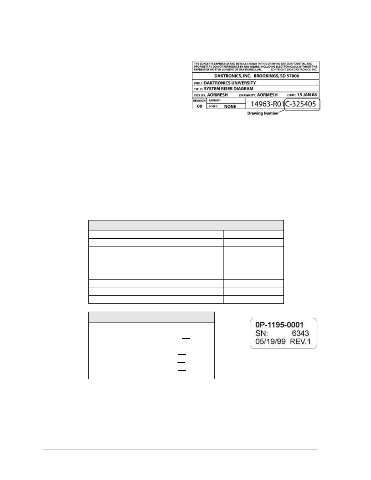
Figure 1: Display ID Label
Section 1: Introduction
This manual explains the installation and maintenance of the Daktronics PC-2002 pace clock display.
For additional information regarding the safety, installation, operation, or service of these displays,
refer to the telephone numbers listed in Section 5.5. This manual is not specific to a particular
installation.
Important Safeguards:
Please read and understand all instructions before beginning the installation process.
Do not drop control equipment or allow it to get wet.
Do not disassemble control equipment or electronic controls of the display; failure to
follow this safeguard will make the warranty null and void.
Disconnect display power when not in use or when servicing.
Disconnect display power before servicing power supplies to avoid electrical shock.
Power supplies run on high voltage and may cause physical injury if touched while
powered.
Do not modify the scoreboard structure or attach any panels or coverings to the
scoreboard without the express written consent of Daktronics, Inc.
Project-specific information takes precedence over any other general information found in
this manual.
1.1 Display Label
Mechanical Installation 1
Serial and model numbers can be found on the ID label on the display as shown in Figure 1.
Please list the model number, display serial number, and the date this display became
operational in the blanks provided on the second page of this manual. When calling
Daktronics customer service, please have this information available to ensure the request is
serviced as quickly as possible.
Page 8
Main Component Labels
Part Type
Part Number
Individual circuit board
0P-XXXX-XXXX
Assembly; a collection of circuit boards
0A-XXXX-XXXX
Wire or cable
W-XXXX
Fuse
F-XXXX
Transformer
T-XXXX
Metal part
M-XXX
Fabricated metal assembly
0S-XXXXXX
Specially ordered part
PR-XXXXX-X
Accessory Labels
Component
Label
Termination block for power
or signal cable
TBXX
Grounding point
EXX
Power or signal jack
JXX
Power or signal plug for the
opposite jack
PXX
Figure 2: Daktronics Drawing Label
Figure 3: Typical Label
1.2 Resources
Figure 2 illustrates a Daktronics drawing
label. The drawing number is located in the
lower-right corner of a drawing. This manual
refers to drawings by listing the last set of
digits and the letter preceding them. In the
example, the drawing would be referred to
as Drawing C-325405.
Reference Drawing:
System Riser Diagram ............................................................................Drawing C-325405
Daktronics identifies manuals by the DD or ED number located on the cover page of each
manual. For example, this manual would be referred to as ED-14253.
1.3 Daktronics Nomenclature
Most components within this display carry a white label that lists the part number of the unit.
If a component is not found in the Replacement Parts List in Section 5.4, use the label to order
a replacement. Figure 3 illustrates a typical label. The part number is in bold.
Following the Replacement Parts List is the Daktronics Exchange Policy and the Repair &
Return Program. Refer to these instructions if replacing or repairing any display component.
1.4 Product Safety Approval
The PC-2002 is ETL-listed, tested to CSA standards, and CE-labeled for indoor use only.
Contact Daktronics with any questions regarding the testing procedures.
2 Mechanical Installation
Page 9
wall anchors
(not provided)
9.70"
Front view Side view
12.00"
9.70"
with surface mounting brackets
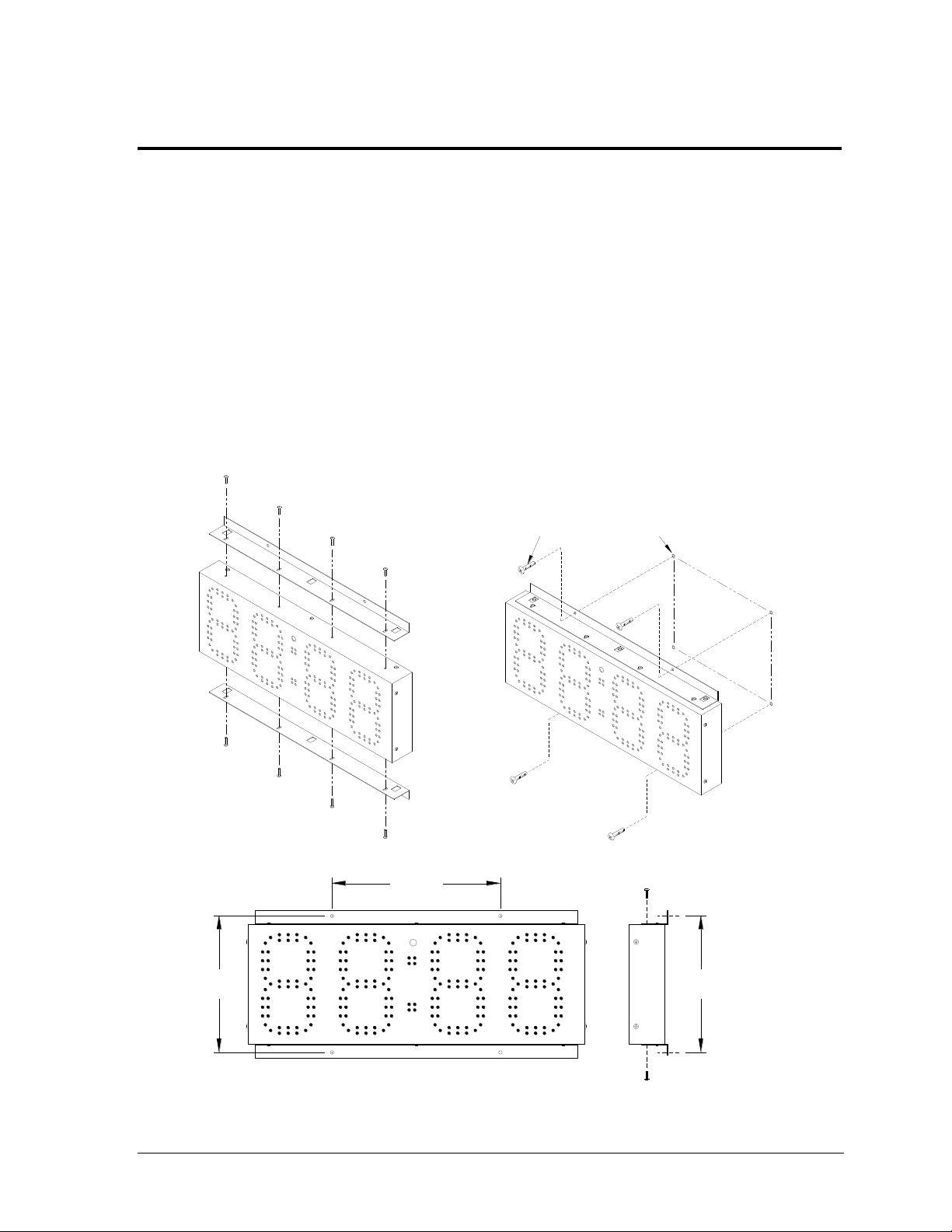
Figure 4: Surface Mounting Installation
3/16" – 1/4" anchors
(not provided)
Side View
Front View
12.0"
9.7"
9.7"
Section 2: Mechanical Installation
This section describes the mounting details of the PC-2002. Use this section when mounting a display
to a wall surface or into a hole in the wall. Other mounting methods can be used, but Daktronics
engineers do not recommend those not documented here. Daktronics is not responsible for mounting
the display. The customer is responsible for providing mounting anchors/screws. A qualified
engineer must specify the mounting anchor type according to national and local building codes.
Note: Daktronics does not assume any liability for any installation derived from the information
provided in this manual or installations designed and installed by others.
2.1 Surface Mounting
The PC-2002 can mount directly to the wall surface using top and bottom mounting brackets.
These brackets then attach to the wall with four anchors. Refer to Figure 4:
Mechanical Installation 3
Page 10
10.00"
25.50"
Wall anchors and
mounting screws
are not provided
Flush mounting bezel
Wall opening
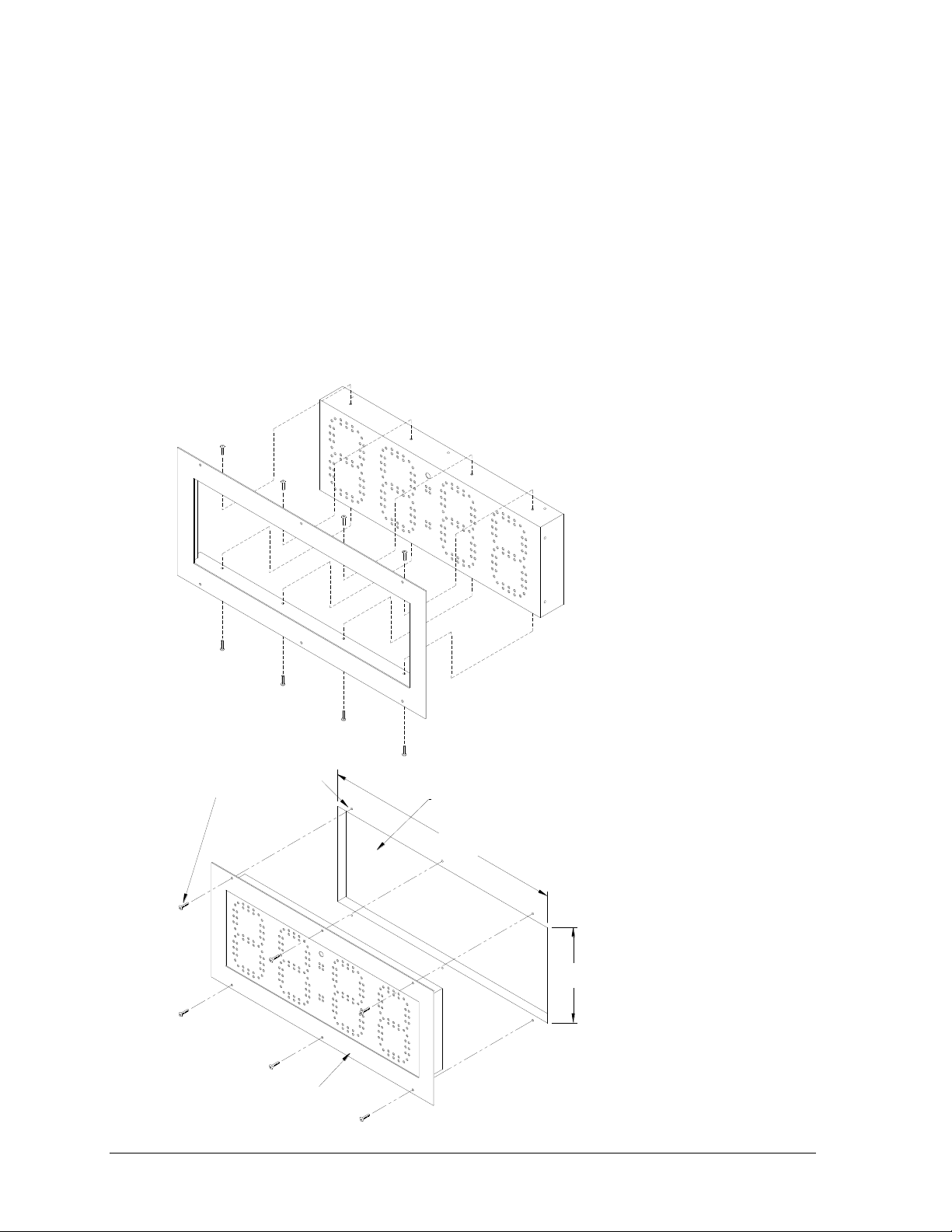
Figure 5: Flush Mounting Installation
Wall anchors/screws
are not provided
Wall opening
Flush mounting bezel
25.5"
10.0"
Attach the brackets to the top and bottom of the display. Level the display against the
mounting surface and make a mark through the anchor holes on the bracket with a marker or
heavy pencil. Drill holes in the wall and install anchors at the marked locations. Minimum
steel anchor size is 3/16" diameter (4.7 mm).
2.2 Flush Mounting
The PC-2002 can be flush mounted into a 25.5" x 10.0" hole in the wall using a mounting
bezel. This bezel then attaches to the wall with 6 anchors. Attach the bezel around the display
with 8 screws. Provide power and signal wiring inside the opening and then connect the
power and signal to the display (see Section 3). Drill holes in the wall and install anchors at
the holes in the bezel. Refer to Figure 5:
4 Mechanical Installation
Page 11
Front view
Recess in the
back of the display
Wall
PC-2002
Wall cutout outline
4.0"
min.
Side view
2.5"
120V AC receptacle
Signal wiring box
25.5"
8.0"
5.0"
Side view
9.70"
1"
min.
Wall
Front view
Power connection may be set up with the receptacle mounted near
the PC-2002 display, or recessed into the wall behind the display.
12.00"
recessed receptacle
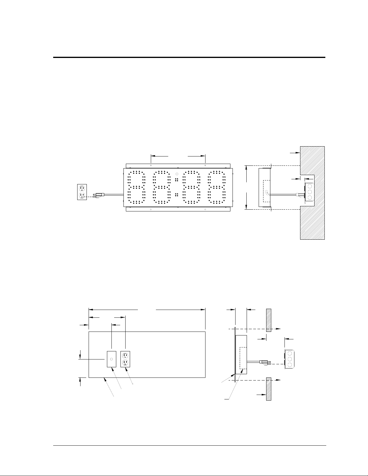
Figure 6: Surface Mounting Electrical Installation
Figure 7: Flush Mounting Electrical Installation
Front View
Side View
Recessed receptacle
Wall
Power connection may be set up with the receptacle
mounted near the PC-2002 display, or recessed into
the wall behind the display.
Front View
Hole Outline
Signal J-box
120 VAC
Side View
Wall
PC-2002
Recess on
display rear
9.7"
12.0"
1"
min.
25.5"
8.0"
5.0"
4.0"
2.5"
4.0"
min.
Section 3: Electrical Installation
Note: Verify that all power is disconnected before working with electrical components; severe injury
or damage to components could occur if the display is serviced while powered.
3.1 Power
The PC-2002 receives external power through a standard 3-prong power cord plugged into a
120 VAC outlet. Figure 6 displays the dimensions for placing the signal J-box and power
outlet to line up with the openings in the back of the display for the surface mount option.
Figure 7 displays the dimensions for placing the signal J-box and power outlet in order to line
up with the openings in the back of the display for the flush mount option.
Electrical Installation 5
Page 12

3.2 Signal
The PC-2002 is designed to work with the JC-100 handheld control console, using 22 AWG
two-pair cable (Daktronics part # W-1234). It is also possible to connect signal in from
Daktronics All Sport® scoring consoles and OmniSport® 2000 timing consoles, and signal out
to multiple displays, using 18 AWG shielded cable (part # W-1117).
Refer to Drawing A-191740 in Appendix A for detailed signal connection information.
6 Electrical Installation
Page 13

MENU-( CUR R MO DE)
1- SET TI NG S {}
Section 4: Controls & Timing Functions
4.1 Program Operations
1. Workout Program or “Pace Clock”. This program is used to structure workouts and
practices. The operator has the option to configure a pace time from 00:00 to 99:59. If the
time is configured to 0:00, the display will count up to 59:99 (mn:sc), roll over to 0:00, and
repeat the cycle. If the time is configured from 0:01 to 99:59, the display will count up to
that time, sound the horn, roll over to 0:00 and repeat the cycle.
2. Count Up or Breakout Timer. This program counts up to the configured time and
sounds the horn. The time can be configured from 00:00 to 99:59. If the time is set to 0:00,
the display will count up to 59:59 (mn:sc), roll over to 0:00, and continue counting.
While the display is counting, a start input will show the split time (time since last start
input) for 10 seconds and then go back to the running time. Pressing <RESET> resets the
timer 0.00. Pressing <RESET> again will return the display to its previous state.
3. Game Clock. This program counts down to zero from a configured time and sounds the
horn. The operator can configure the time from 00:00 to 99:59 (mn:sc). If the time is set to
0:00, the display will count down to 0:00, roll over to 59:59, and continue counting down.
Pressing RESET resets the timer to the configured time.
4. Shot Clock. In this program, the display shows the tens and ones of seconds on the two
center digits. The display counts down to 0:00 from a configured time and sounds the
horn. The operator can configure the time from 0 to 99 seconds. In this mode, a START
will start the display counting; a STOP will stop the display from counting. This mode
automatically configures the PC-2002 to receive the signal from an All Sport® console or
an OmniSport® timer for use as a shot clock display (such as for water polo).
5. 12-Hour Time of Day. This program displays the time of day in 12-hour format.
6. 24-Hour Time of Day. This program displays the time of day in 24-hour format.
7. Slave mode (receive only). In this mode, the display will only show information received
via signal from an All Sport® or OmniSport® control console. If no signal is present the
display will be blank.
4.2 JC-100 Console Operation
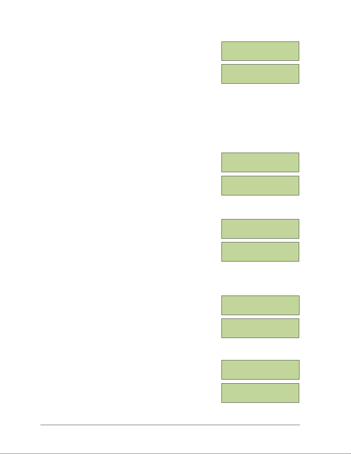
Connect the 4-pin power/signal cable from the JC-100 Judges Console to a J-box, and from
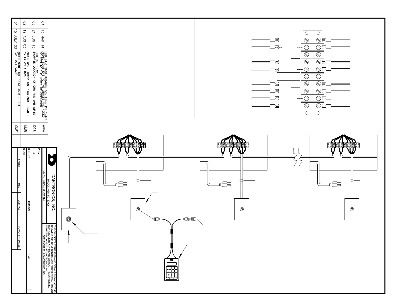
the J-box to the PC-2002 as shown in Drawing A-191740 in Appendix A. The keypad insert
number needed for operation is LL-2584 (Drawing A-191855).
When the PC-2002 is turned on and the JC-100 is connected, press <MENU> on the control
console to view the available options. Use the up and down arrows to scroll through these
options, or press the number located next to the option.
Press <ENTER> when the desired action is on the screen.
Press the <MENU> button at any time to exit.
Controls & Timing Functions 7
Page 14

MENU-S ETT I NGS
1- TI ME {}
EN TER TI ME
00 :00 *
MENU-S ETT I NGS
1- I NTE NSI T Y {}
I NT ENS I TY( 1-16)
=1 6 *
MENU-S ETT I NGS
3- HOR N {}
HO RN C ONF I G
(AUTO)*
MENU-( CUR R MO DE)
2- CHA NGE MOD E {}
MENU-C HAN GE M ODE
1- WORKOUT {}
MENU-WORKOUT
1- EDI T WOR KOU T
ED I T STEP 1*
PA CE 0 0:0 0
The settings will need to be changed to fit the user‟s specific needs, but once the program has
the desired settings, the console will remember those settings for next use. The available
settings and menu numbers will vary by the current mode.
Time
The Time setting lets users enter desired timing options for
the mode. To change the preset time, press <MENU>, and
then press <ENTER>. Press <ENTER>, input the desired
time using the keypad, and then press <ENTER> once more.
Note: For 12 Hour Time of Day (mode 5), users must also
select whether the time is AM or PM using the arrow keys.
Intensity
The Intensity setting lets users manipulate the brightness of
the LED digits. The settings for intensity range from 1 to 16,
with 16 being the brightest (default). To change the display‟s
intensity, press <MENU>, and then press <ENTER>. Scroll
down to 2-INTENSITY and press <ENTER>. Use the up and
down arrows or the keypad to adjust the intensity. When
finished, press <ENTER>.
Horn
The Horn setting lets users switch between an automatic
horn and a manual horn. To change the Horn settings, press
<MENU>, and then press <ENTER>. Scroll down to 3-
HORN and press <ENTER>. Press <ENTER> again to allow
the selection of the Horn option. Use the up and down
arrows to select between the AUTO (default) and MANUAL,
and then press <ENTER>.
After selecting the desired settings, refer to the sections below for operation instructions of
specific modes.
To select a mode, press <MENU> and go to the 2-CHANGE
MODE option. Use the arrow keys or press the number keys
to select a particular mode, and then press <ENTER>.
Mode #1: Workout
To edit a workout, press <MENU> followed by <ENTER>
on the 1-EDIT WORKOUT option. Select the step number to
change or add and press <ENTER>. To select the step type,
scroll up or down through the options and press <ENTER>
on the desired step type. There are six different step options
to work with:
STOP – This step allows users to enter where to end
or "Stop" a workout.
BEG CIRCUIT – This step allows users to enter a set of
steps to repeat a set number of times within a workout.
Basically, this is a workout within the whole workout.
8 Controls & Timing Functions
Page 15

MENU-WORKOUT
2- I NSE RT S TEP {}
I NS ERT @ST EP 3 *
STOP
MENU-WORKOUT
3- DEL ETE STE P
DE LET E ST EP 3 *
STOP
MENU-WORKOUT
4- CLE AR W ORK OUT
CL EAR WOR KOU T?
PR ESS ENT ER
MENU-WORKOUT
5- SET TI NG S {}
MENU-S ETT I NGS
2- HOR N {}
MENU-HORN
1- SWI M (OF F) { }
After pressing <ENTER> to select this step, the user is prompted to enter the number
of times this circuit is to be repeated. Adding different steps within this circuit is the
same as adding steps to the whole workout. The user will be prompted to enter the
amount of times each step within the circuit is to be repeated as they are added.
END CIRCUIT – This step will end the circuit that that was entered within the BEG
CIRCUIT option. After ending a circuit, additional steps may still be added to the rest
of the total workout.
SWIM – This step allows users to enter the amount of time to have the swimmer(s)
swim within one step.
REST – This step allows users to enter the amount of time to have the swimmer(s)
rest within one step.
PACE – This step allows users to enter a pace step that will override the rest of the
workout (or circuit if a pace step is entered within one) and continue to count up to
the entered time, return to 0:00 and start counting again. It will repeat this step
indefinitely.
To insert a step, press <MENU>, scroll down to 2-INSERT
STEP, and then press <ENTER>. Select the step number to
insert after using the arrow keys or number pad, and then
press <ENTER> to insert a new step into the workout.
To delete a step, press <MENU>, scroll down to 3-DELETE
STEP, and then press <ENTER>. Select the step number to
delete using the arrow keys or number pad, and then press
<ENTER> to remove the step from the workout.
To clear the entire workout, press <MENU> and scroll down
to 4-CLEAR WORKOUT and then press <ENTER>. On the
screen that appears, press <ENTER> to confirm the whole
workout is to be cleared.
After entering all the desired timing options, press <START> to begin the workout.
Horn
The workout mode has a few different horn options than
other modes. To access the horn settings, press <MENU>,
scroll down to 5-SETTINGS, and then press <ENTER>.
Scroll down to 2-HORN and press <ENTER> once more.
Here the user can individually select the horn settings for
swim steps and rest steps. Scroll to the desired step setting
and press <ENTER>. Select a horn mode (3 for swim, 2 for
rest), and then press <ENTER> to save the horn setting.
Controls & Timing Functions 9
Page 16
MENU-C HAN GE M ODE
2- BREAKOUT {}
PRESET= 00:00
0.0
MENU-C HAN GE M ODE
3- GAM E CL OCK {}
GA ME C LOC K 15 :00
HO RN= AUT O
MENU-C HAN GE M ODE
4- SHO T CL OCK {}
SH OT C LOC K 35
HO RN= AUT O
MENU-C HAN GE M ODE
5- 12H R T. O.D . {}
12 HR T I ME O F DA Y
12:00AM
MENU-C HAN GE M ODE
6- 24H R T. O.D . {}
24 HR T I ME O F DA Y
13:00
Mode #2: Breakout
Press the <START> key to start the clock counting up.
Pressing the <START> key again will display an individual
lap time and will allow the total time to continue running.
The laps will be numbered up to 99 and then start over at 1.
Pressing the <STOP> key stops the clock and shows the lap time. After pressing the
<START> key again, the clock will resume counting up from the stopped time. These
procedures can be followed as many times as allowed before the preset time is reached. If
there is no preset time, the procedure may be used as many times as desired. Press the
<RESET> key to start the program over.
Mode #3: Game Clock
Press the <START> key to start the clock counting down
from the preset time. Press the <STOP> key to stop the
clock. Press the <START> key to resume the countdown.
This procedure may be repeated until the clock reaches 0.00.
Press <RESET/CLEAR> to return the game clock to the
original preset time.
Mode #4: Shot Clock
Press the <START> key to start the countdown from the
preset shot clock time. While the clock is running, press the
<RESET> key to start the clock over again at the preset time
and automatically start counting down. Press the <STOP>
key to pause the countdown. When the clock is stopped,
pressing <RESET> will place the clock at the preset time;
however, <START> must then be pressed to resume the
countdown as it will not begin automatically.
Mode #5: 12 Hour Time of Day
To change the time of day, press <MENU>, and then press
<ENTER>. Press <ENTER>, input the desired time using
the keypad, and then press <ENTER> once more. Select
whether the time is AM or PM using the arrow keys, and
then press <ENTER> to save the time of day settings.
Mode #6: 24 Hour Time of Day
To change the time of day, press <MENU>, and then press
<ENTER>. Press <ENTER>, input the desired time using
the keypad, and then press <ENTER> once more.
10 Controls & Timing Functions
Page 17

4.3 Team Manager
The Daktronics PC-2002 can interface with third-party Hy-Tek™ TEAM MANAGER with
WORKOUT MANAGER software for easy entry of workouts from a computer to the display.
The TEAM MANAGER must have the Workout Manager Basic option configured. After
creating a workout in the Hy-Tek software:
1. Turn on the PC-2002, connect the JC-100 console, and set to mode 1–WORKOUT.
2. The interface cable (Daktronics part # 0A-1153-0036) has a 9-pin serial connector on
one end and a stereo phone jack connector on the other end. Connect the 9-pin plug
to an available COM port on the Hy-Tek computer.
Note: If the Hy-Tek computer does not have a serial port, the user must purchase and
install a USB to serial adaptor.
3. Plug the stereo phone jack into a J-box (part # 0A-1091-0227). Route minimum 18
AWG shielded cable (part # W-1117) from the J-box to the SIGNAL IN terminal block
on the rear of the display (red to TB-1, black to TB-2).
Drawing A-195172 in Appendix A illustrates the connections needed to download
information onto the PC-2002 from the Hy-Tek software.
4. From TEAM MANAGER‟s main menu, go to Workouts > Pace Clock > Daktronics
Pace Clock.
5. At the top of the Daktronics Pace Clock menu, select the Daktronics PC-2000 button.
Select the Verify menu at the top of the screen and enter the serial port number that
the cable is connected to (most likely 1), and then click OK.
6. Double-click on the desired workout from the list of available workouts at the bottom
of the screen (or simply type the workout number into lane 1). The workout will
appear in lane one under Pace Clock Workout Lane Assignments. The download will
only download lane 1‟s workout.
7. Click on the Transfer menu in the upper left of the screen. A message should appear
that reads, "Transfer completed for lanes 1." Click OK. The PC-2002 should read
“donE”. If this does not happen, the download did not work properly.
8. Start the PC-2002 workout by pressing the <START> key on the JC-100.
Controls & Timing Functions 11
Page 18

Page 19

Screw
(HC-1489)
Case
Back
Circuit Board
Part number varies
with model number
Case
Front
Spacer
(HE-1357)
6-32 Nut
(HS-1354)
Transformer
(T-1082)
Figure 8: PC-2002 Exploded View
Rear Panel
Front Panel
Spacer
(HE-1357)
Screw
(HC-1489)
8-32 Nut
(HC-1354)
Printed Circuit Board
(Indoor: 0P-1153-0005)
Transformer
(T-1082)
Section 5: Display Maintenance
IMPORTANT NOTES:
1. Disconnect power before doing any repair work on the scoreboard.
2. Allow only qualified service personnel access to internal display electronics.
3. Disconnect power when not using the scoreboard.
5.1 Digit/Driver Printed Circuit Board
The PC-2002 uses a single printed circuit board (PCB) that contains all of the electronics
needed to make this system work: digit LEDs, control processors, power input connectors,
horn, and other components. All switches, power systems, and input/output terminations are
connected to the PCB.
As shown in Figure 8, the PCB is attached to the front panel of the display. Refer to Section
5.2 for instructions on accessing and replacing the PCB.
Display Maintenance 13
Page 20

Description
Daktronics Part #
Indoor PCB
0P-1153-0005
Flush Mount Hardware
0A-1153-0411
Surface Mount Hardware
0A-1153-0412
12 V Buzzer
DS-1487
Transformer, 120 V AC
T-1082
5.2 Replacing the Digit/Driver Printed Circuit Board
1. To access the digit/driver PCB, remove the 10 outer screws to separate the front and
back panels of the display.
2. Disconnect all power and signal connections from the PCB by squeezing together the
locking tabs and pulling the connector free.
3. Remove the 8 nuts securing the PCB to the front panel of the display. Take note of the
orientation of the PCB for future reference.
4. Carefully remove the PCB from the studs and spacers on the front panel. Use an even
force to prevent any damage that might result from bending the LEDs or connector
pins on the board.
5. Position the new PCB over the studs, making sure there is a spacer between the front
panel and circuit board.
6. Tighten the 8 nuts.
7. Reconnect all power/signal connectors.
Note: These are keyed connectors and will attach in one way only. Do not attempt to
force the connections.
8. Close and secure the back panel, then power on and test the display.
5.3 Schematics
For advanced scoreboard troubleshooting and repair, it may be necessary to consult the
schematic drawing. Drawing A-187843 in Appendix A shows detailed power and signal
wiring diagrams of internal display components.
5.4 Replacement Parts List
Refer to the following table for Daktronics replacement parts:
14 Display Maintenance
Page 21

Market Description
Customer Service Number
Schools (including community/junior colleges), religious
organizations, municipal clubs and community centers
877-605-1115
Universities and professional sporting events, live events
for auditoriums and arenas
866-343-6018
5.5 Daktronics Exchange and Repair & Return Programs
Exchange Program
The Daktronics Exchange Program is a quick, economical service for replacing key
components in need of repair. If a component fails, Daktronics sends a replacement part to
the customer who, in turn, returns the failed component to Daktronics. This not only saves
money but also decreases equipment downtime. Customers who follow the program
guidelines explained below will receive this service.
Before Contacting Daktronics
Identify these important numbers:
Display Serial Number: _________________________________________________________
Display Model Number: _________________________________________________________
Job/Contract Number: __________________________________________________________
Date Installed: _________________________________________________________________
Daktronics Customer ID Number: ________________________________________________
To participate in the Exchange Program, follow these steps.
1. Call Daktronics Customer Service.
2. When the new exchange part is received, mail the old part to Daktronics.
If the replacement part fixes the problem, send in the problem part being replaced.
a. Package the old part in the same shipping materials in which the replacement
part arrived.
b. Fill out and attach the enclosed UPS shipping document.
c. Ship the part to Daktronics.
3. The defective or unused parts must be returned to Daktronics within 5 weeks of
initial order shipment.
If any part is not returned within five (5) weeks, a non-refundable invoice will be
presented to the customer for the costs of replenishing the exchange parts inventory
with a new part.
Daktronics reserves the right to refuse parts that have been damaged due to acts of
nature or causes other than normal wear and tear.
Display Maintenance 15
Page 22

Repair & Return Program
For items not subject to exchange, Daktronics offers a Repair & Return Program. To send a
part for repair, follow these steps:
1. Call or fax Daktronics Customer Service:
Refer to the appropriate market number in the chart listed on the previous page.
Fax: 605-697-4444
2. Receive a case number before shipping.
This expedites repair of the part.
3. Package and pad the item carefully to prevent damage during shipment.
Electronic components, such as printed circuit boards, should be placed in an
antistatic bag before boxing. Daktronics does not recommend using packing „peanuts‟
when shipping.
4. Enclose:
name
address
phone number
the case number
a clear description of symptoms
Shipping Address
Daktronics Customer Service
[Case #]
201 Daktronics Drive, Dock E
Brookings, SD 57006
Daktronics Warranty and Limitation of Liability
The Daktronics Warranty and Limitation of Liability is located in Appendix B. The Warranty
is independent of Extended Service agreements and is the authority in matters of service,
repair, and display operation.
16 Display Maintenance
Page 23

Appendix A: Reference Drawings
Drawing Title Drawing Number
Schematic; PC-2002 ................................................................................................................. A-187843
Riser Diagram; PC-2002 Permanent Install ............................................................................. A-191740
Insert, LL-2584, JC-100 Pace Clock ........................................................................................ A-191855
Riser Diagram; PC-2001 & PC-2002 ........................................................................................ A-195172
Reference Drawings 17
Page 24

Page 25

THE CONCEPTS EXPRESSED AND DETAILS SHOWN ON THIS
DRAWING ARE CONFIDENTIAL AND PROPRIETARY. DO NOT
REPRODUCE BY ANY MEANS WITHOUT THE EXPRESSED
WRITTEN CONSENT OF DAKTRONICS, INC.
COPYRIGHT 2013 DAKTRONICS, INC.
DAKTRONICS, INC.
AV
DRAWN: DATE:
SHEET JOB NO:REV
SCHEMATIC- PC-2002
CBRECZI 29 APR 03
P1153 R
03 A
1=1
CBRECZI
187843
04
Page 26
DAKTRONICS
R
1
2
3
4
5
6
7
8
10
9
PACE CLOCK
RED
BLK
BLK
RED
W-1117 W-1117
@1000'
MAX MAX
@1000'
W-1117
RED
WHT
GRN
BLK
W-1234 W-1234 W-1234
SIG OUT +
SIG IN -
SIG IN +
SIG OUT -
CAN H
CAN L
CAN GND
CAN PWR
PC-2002 TERM BLOCK
FROM
JC-100
J-BOX
TO NEXT
PC-2002
JUDGES CONSOLE
JC-100
0A-1240-0027
0A-1091-0227
TYPICAL
REAR VIEW OF
PC-2002
FROM PREVIOUS
PC-2002 OR
OA-1091-0227
J-BOX
NOTES OF OPERATION:
ONLY ONE JUDGE CONSOLE PER CLOCK.
YOU MAY RUN ALL CLOCKS WITH AN OMNISPORT OR
ALLSPORT CONSOLE FROM JB#1 LOCATION. ALSO YOU
MAY RUN RUN ALL CLOCKS FROM JB#2 LOCATION, WITH
THE JC-100.
YOU MAY TIE TOGETHER AN UNLIMITED NUMBER OF
CLOCKS FOR CUSTOMER SATISFACTION.
TO OPERATED ONLY THE CLOCK AT JB#3 OR OTHER
JB#X LOCATIONS, THE "SIG IN" WIRES NEED TO BE
DISCONNECTED AT THAT CLOCK.
@20' @20' @20'
1/4" PHONE JACK FOR
CONNECTION FROM
ALLSPORT OR
OMNISPORT CONSOLES.
WORKOUT DOWNLOADS
WOULD ALSO BE DONE
THROUGH THIS J-BOX
0A-1241-4010
ASSY., CAN
TERMINATOR
PLUG
AH
RISER DIAGRAM: PC-2002 PERMENANT INSTALL
CENGELS 07 JULY 03
P1153 R
01 A
1=5
JWARNE
191740
04
JB#1
JB#2
JB#3 JB#X
Page 27
JC-100
SWIM STOPREST
LL-2584, REV 01
CIRCUIT
PACE CLOCK
Page 28

Page 29

Appendix B: Daktronics Warranty and Limitation
of Liability
Daktronics Warranty and Limitation of Liability 19
Page 30

Page 31

Copyright © Daktronics, Inc. SL-02374 Rev 10 02-Mar-2009 Page 1 of 2
DAKTRONICS
WARRANTY AND LIMITATION OF LIABILITY
This Warranty and Limitation of Liability (the “Warranty”) sets forth the warranty provided by Daktronics with respect to the Equipment. By
accepting delivery of the Equipment, Purchaser agrees to be bound by and accept these terms and conditions. All defined terms within
the Warranty shall have the same meaning and definition as provided elsewhere in the Agreement.
DAKTRONICS WILL ONLY BE OBLIGATED TO HONOR THE WARRANTY SET FORTH IN THESE TERMS AND CONDITIONS UPON RECEIPT OF FULL
PAYMENT FOR THE EQUIPMENT.
1. Warranty Coverage
2. Exclusion from Warranty Coverage
A. Daktronics warrants to the original end-user that the Equipment will be free from Defects (as defined below) in materials and
workmanship for a period of one (1) year (the “Warranty Period”). The warranty period shall commence on the earlier of: (i) four
weeks from the date that the equipment leaves Daktronics’ facility; or (ii) Substantial Completion as defined herein. The warranty
period shall expire on the first anniversary of the commencement date.
“Substantial Completion” means the operational availability of the Equipment to the Purchaser in accordance with the
Equipment’s specifications, without regard to punch-list items, or other non-substantial items which do not affect the operation of
the Equipment.
B. Daktronics’ obligation under this Warranty is limited to, at Daktronics’ option, replacing or repairing, any Equipment or part
thereof that is found by Daktronics not to conform to the Equipment’s specifications. Unless otherwise directed by Daktronics,
any defective part or component shall be returned to Daktronics for repair or replacement. Daktronics may, at its option,
provide on-site warranty service. Daktronics shall have a reasonable period of time to make such replacements or repairs and
all labor associated therewith shall be performed during regular working hours. Regular working hours are Monday through
Friday between 8:00 a.m. and 5:00 p.m. at the location where labor is performed, excluding any holidays observed by either
Purchaser or Daktronics.
C. Daktronics shall pay ground transportation charges for the return of any defective component of the Equipment. If returned
Equipment is repaired or replaced under the terms of this warranty, Daktronics will prepay ground transportation charges back to
Purchaser; otherwise, Purchaser shall pay transportation charges to return the Equipment back to the Purchaser. All returns must
be pre-approved by Daktronics before shipment. Daktronics shall not be obligated to pay freight for any unapproved return.
Purchaser shall pay any upgraded or expedited transportation charges.
D. Any replacement parts or Equipment will be new or serviceably used, comparable in function and performance to the
original part or Equipment, and warranted for the remainder of the Warranty Period. Purchasing additional parts or Equipment
from the Seller does not extend this Warranty Period.
E. Defects shall be defined as follows. With regard to the Equipment (excepting LEDs), a “Defect” shall refer to a material
variance from the design specifications that prohibit the Equipment from operating for its intended use. With respect to LEDs,
“Defects” are defined as LED pixels that cease to emit light. The limited warranty provided by Daktronics does not impose any
duty or liability upon Daktronics for partial LED pixel degradation. Nor does the limited warranty provide for the replacement or
installation of communication methods including but not limited to, wire, fiber optic cable, conduit, trenching, or for the purpose
of overcoming local site interference radio equipment substitutions.
THIS LIMITED WARRANTY IS THE ONLY WARRANTY APPLICABLE TO THE EQUIPMENT AND REPLACES ALL OTHER WARRANTIES OR
CONDITIONS, EXPRESS OR IMPLIED, INCLUDING, BUT NOT LIMITED TO, THE IMPLIED WARRANTIES OR CONDITIONS OF
MERCHANTABILITY AND FITNESS FOR A PARTICULAR PURPOSE. SPECIFICALLY, EXCEPT AS PROVIDED HEREIN, THE SELLER
UNDERTAKES NO RESPONSIBILITY FOR THE QUALITY OF THE EQUIPMENT OR THAT THE EQUIPMENT WILL BE FIT FOR ANY PARTICULAR
PURPOSE FOR WHICH PURCHASER MAY BE BUYING THE EQUIPMENT. ANY IMPLIED WARRANTY IS LIMITED IN DURATION TO THE
WARRANTY PERIOD. NO ORAL OR WRITTEN INFORMATION, OR ADVICE GIVEN BY THE COMPANY, ITS AGENTS OR EMPLOYEES,
SHALL CREATE A WARRANTY OR IN ANY WAY INCREASE THE SCOPE OF THIS LIMITED WARRANTY.
THIS LIMITED WARRANTY IS NOT TRANSFERABLE.
The limited warranty provided by Daktronics does not impose any duty or liability upon Daktronics for:
A Any damage occurring, at any time, during shipment of Equipment unless otherwise provided for in the Agreement. When
returning Equipment to Daktronics for repair or replacement, Purchaser assumes all risk of loss or damage, and agrees to use
any shipping containers that might be provided by Daktronics and to ship the Equipment in the manner prescribed by
Daktronics;
B. Any damage caused by the unauthorized adjustment, repair or service of the Equipment by anyone other than personnel of
Daktronics or its authorized repair agents;
Page 32

Copyright © Daktronics, Inc. SL-02374 Rev 10 02-Mar-2009 Page 2 of 2
C. Damage caused by the failure to provide a continuously suitable environment, including, but not limited to: (i) neglect or
misuse, (ii) a failure or sudden surge of electrical power, (iii) improper air conditioning or humidity control, or (iv) any other cause
other than ordinary use;
D. Damage caused by fire, flood, earthquake, water, wind, lightning or other natural disaster, strike, inability to obtain materials
or utilities, war, terrorism, civil disturbance or any other cause beyond Daktronics’ reasonable control;
E. Failure to adjust, repair or replace any item of Equipment if it would be impractical for Daktronics personnel to do so because
of connection of the Equipment by mechanical or electrical means to another device not supplied by Daktronics, or the
existence of general environmental conditions at the site that pose a danger to Daktronics personnel;
F. Any statements made about the product by salesmen, dealers, distributors or agents, unless such statements are in a written
document signed by an officer of Daktronics. Such statements as are not included in a signed writing do not constitute
warranties, shall not be relied upon by Purchaser and are not part of the contract of sale;
G. Any damage arising from the use of Daktronics products in any application other than the commercial and industrial
applications for which they are intended, unless, upon request, such use is specifically approved in writing by Daktronics; or
H. Any performance of preventive maintenance.
3. Limitation of Liability
4. Assignment of Rights
5. Dispute Resolution
6. Governing Law
7. Availability of Extended Service Agreement
Daktronics shall be under no obligation to furnish continued service under this Warranty if alterations are made to the Equipment
without the prior written approval of Daktronics.
It is specifically agreed that the price of the Equipment is based upon the following limitation of liability. In no event shall
Daktronics (including its subsidiaries, affiliates, officers, directors, employees, or agents) be liable for any special, consequential,
incidental or exemplary damages arising out of or in any way connected with the Equipment or otherwise, including but not
limited to damages for lost profits, cost of substitute or replacement equipment, down time, lost data, injury to property or any
damages or sums paid by Purchaser to third parties, even if Daktronics has been advised of the possibility of such damages. The
foregoing limitation of liability shall apply whether any claim is based upon principles of contract, tort or statutory duty, principles
of indemnity or contribution, or otherwise.
In no event shall Daktronics be liable to Purchaser or any other party for loss, damage, or injury of any kind or nature arising out of
or in connection with this Warranty in excess of the purchase price of the Equipment actually delivered to and paid for by the
Purchaser. The Purchaser’s remedy in any dispute under this Warranty shall be ultimately limited to the Purchase Price of the
Equipment to the extent the Purchase Price has been paid.
The Warranty contained herein extends only to the original end-user (which may be the Purchaser) of the Equipment and no
attempt to extend the Warranty to any subsequent user-transferee of the Equipment shall be valid or enforceable without the
express written consent of Daktronics.
Any dispute between the parties will be resolved exclusively and finally by arbitration administered by the American Arbitration
Association (“AAA”) and conducted under its rules, except as otherwise provided below. The arbitration will be conducted
before a single arbitrator. The arbitration shall be held in Brookings, South Dakota. Any decision rendered in such arbitration
proceedings will be final and binding on each of the parties, and judgment may be entered thereon in any court of competent
jurisdiction. This arbitration agreement is made pursuant to a transaction involving interstate commerce, and shall be governed
by the Federal Arbitration Act.
The rights and obligations of the parties under this warranty shall not be governed by the provisions of the United Nations
Convention on Contracts for the International Sales of Goods of 1980. Both parties consent to the application of the laws of the
State of South Dakota to govern, interpret, and enforce all of Purchaser and Daktronics rights, duties, and obligations arising
from, or relating in any manner to, the subject matter of this Warranty, without regard to conflict of law principles.
For Purchaser’s protection, in addition to that afforded by the warranties set forth herein, Purchaser may purchase extended
warranty services to cover the Equipment. The Extended Service Agreement, available from Daktronics, provides for electronic
parts repair and/or on-site labor for an extended period from the date of expiration of this warranty. Alternatively, an Extended
Service Agreement may be purchased in conjunction with this warranty for extended additional services. For further information,
contact Daktronics Customer Service at 1-800-DAKTRONics (1-800-325-8766).
 Loading...