

Page 1
Models
BA-1518
FB-2021
MS-2009
BA-2025
FB-2022
MS-2918
BA-2026
FB-2023
SO-2011
BA-2027
FB-2024
SO-2018
BA-2028
FB-2025
SO-2019
BA-2029
FB-2026
SO-2021
FB-2018
FB-2027
SO-2023
FB-2019
FB-2028
SO-2043
FB-2020
FB-3010
201 Daktronics Drive PO Box 5128 Brookings, SD 57006-5128
Tel: 1-800-DAKTRONICS (1-800-325-8766) Fax: 605-697-4746
www.daktronics.com/support
P1647 Multi-Section
Outdoor LED Scoreboards
Installation Manual
DD1969938 Rev 6 – 11 June 2013
Page 2

Page 3

DD1969938
Product 1647
Rev 6 – 11 June 2013
DAKTRONICS, INC.
Copyright 2011-2013
All rights reserved. While every precaution has been taken in the preparation of this manual, the publisher
assumes no responsibility for errors or omissions. No part of this book covered by the copyrights hereon may be
reproduced or copied in any form or by any means – graphic, electronic, or mechanical, including photocopying,
taping, or information storage and retrieval systems – without written permission of the publisher.
All Sport® and PanaView® are trademarks of Daktronics, Inc. Other trademarks used in this manual are the property of their
respective owners.
Page 4

Page 5

Table of Contents
Section 1: Introduction ............................................................................................................................ 1
1.1 Scoreboard Controllers ........................................................................................................... 1
Sport Codes ....................................................................................................................... 1
1.2 Troubleshooting ...................................................................................................................... 1
1.3 Specifications Label................................................................................................................. 2
1.4 Resources .................................................................................................................................. 2
1.5 Product Safety Approval........................................................................................................ 2
Section 2: Mechanical Installation ........................................................................................................ 3
2.1 Lifting the Scoreboard ............................................................................................................ 3
2.2 Scoreboard Mounting ............................................................................................................. 4
I-Beam Clamps ................................................................................................................. 5
Clamping Angles ............................................................................................................. 6
2.3 Ad Panel Mounting................................................................................................................. 7
Unistrut Attachment ........................................................................................................ 7
I-Beam Clamps ................................................................................................................. 8
2.4 Scoreboard Protective Devices .............................................................................................. 9
Section 3: Electrical Installation .......................................................................................................... 11
3.1 Installation Overview ........................................................................................................... 11
3.2 Power ...................................................................................................................................... 12
Grounding ....................................................................................................................... 13
Connection ...................................................................................................................... 13
3.3 Power-On Self-Test (POST) ................................................................................................. 14
Radio Settings ................................................................................................................. 15
3.4 Signal Connection ................................................................................................................. 15
Fiber Optic ...................................................................................................................... 15
Multiple Driver Connections ........................................................................................ 16
3.5 Power/Signal Connections Between Sections ................................................................... 16
Two-Section Models ...................................................................................................... 16
Four-Section Models ...................................................................................................... 17
3.6 Lightning Protection ............................................................................................................. 19
Section 4: Daktronics Exchange and Repair & Return Programs .................................................. 21
4.1 Exchange Program ................................................................................................................ 21
Before Contacting Daktronics....................................................................................... 21
4.2 Repair & Return Program .................................................................................................... 22
Shipping Address .......................................................................................................... 22
4.3 Daktronics Warranty and Limitation of Liability ............................................................. 22
Section 5: Scoreboard Options ............................................................................................................. 23
5.1 Team Name Message Centers (TNMCs) ............................................................................ 23
5.2 Trumpet Horns ...................................................................................................................... 23
5.3 Radio Control......................................................................................................................... 23
5.4 Time Outs Left (T.O.L) Digits .............................................................................................. 23
5.5 Changeable Caption Kits...................................................................................................... 24
Table of Contents i
Page 6

Appendix A: Specifications ........................................................................................................................ 25
Appendix B: Reference Drawings ............................................................................................................ 27
Appendix C: Daktronics Warranty and Limitation of Liability .......................................................... 29
ii Table of Contents
Page 7
Sport
Common Code(s)
All Sport 5000
Baseball
5501
Pitch & Speed
5500
Football
6601
Lacrosse/
Field Hockey
4601
Soccer
7701
Track
8601 (manual timing)
Section 1: Introduction
This manual explains the installation of Daktronics Multi-Section Outdoor LED Scoreboards
(Product 1647). For additional information regarding the safety, installation, operation, or service of
this system, refer to the telephone numbers listed in Section 4. This manual is not specific to a
particular installation. Project-specific information takes precedence over any other general
information found in this manual.
IMPORTANT SAFEGUARDS:
Please read and understand all instructions before beginning the installation process.
Do not drop control equipment or allow it to get wet.
Do not disassemble control equipment or electronic controls of the display; failure to
follow this safeguard will make the warranty null and void.
Disconnect display power when not in use or when servicing.
Disconnect display power before servicing power supplies to avoid electrical shock.
Power supplies run on high voltage and may cause physical injury if touched while
powered.
Do not modify the scoreboard structure or attach any panels or coverings to the
scoreboard without the express written consent of Daktronics, Inc.
1.1 Scoreboard Controllers
Daktronics outdoor scoreboards are designed for use with the All Sport® 5000 series control
consoles. This console uses keyboard overlays (sport inserts) to control numerous sports and
scoreboard models. Refer to the following manual for operating instructions:
All Sport 5000 Series Control Console Operation Manual (ED-11976)
The scoreboard controller manual is available online at www.daktronics.com/manuals.
Sport Codes
At right is a table of common sport codes. Note
that many scoreboards are capable of scoring
multiple sports. Refer to the Operation Manuals
for a complete listing of sport codes.
1.2 Troubleshooting
For an extensive troubleshooting guide and instructions on how to replace scoreboard
components, refer to the following manual:
Outdoor LED Scoreboards Service Manual (DD2124597)
The service manual is available online at www.daktronics.com/manuals.
Introduction 1
Page 8
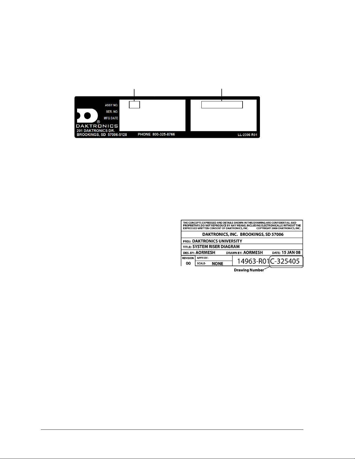
Figure 1: Specifications Label
Figure 2: Daktronics Drawing Label
0A-1647-0012 HRev: 00
SN: 1001
05/15/13
3219728 0001
BA-2025-201X
VOLTS: 120V AC
AMPS: 7.5
WATTS: 900
Product Number
Model Number
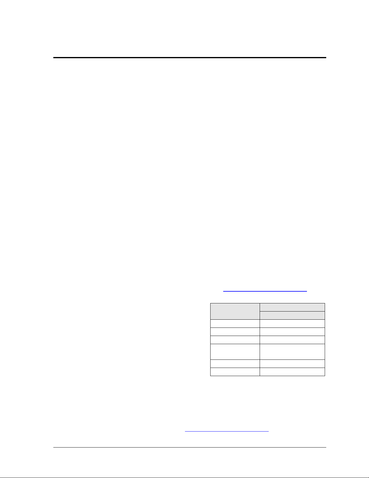
1.3 Specifications Label
Power specifications as well as serial and model number information can be found on an ID
label on the display, similar to the one shown in Figure 1.
Please have the assembly number, model number, and the date manufactured on hand when
calling Daktronics customer service to ensure the request is serviced as quickly as possible.
Knowing the facility name and/or job number will also be helpful. Note that the Product
Number(s) are sometimes used to distinguish different generations of the scoreboards having
the same model number.
1.4 Resources
Figure 2 illustrates a Daktronics drawing
label. The drawing number is located in the
lower-right corner of a drawing. This
manual refers to drawings by listing the last
set of digits and the letter preceding them.
In the example, the drawing would be
referred to as Drawing C-325405.
Daktronics identifies manuals by the DD or
ED number located on the cover page of each manual. For example, this manual would be
referred to as DD1969938.
1.5 Product Safety Approval
Daktronics outdoor scoreboards are ETL listed and tested to CSA standard for outdoor use.
Contact Daktronics with any questions regarding testing procedures.
2 Introduction
Page 9
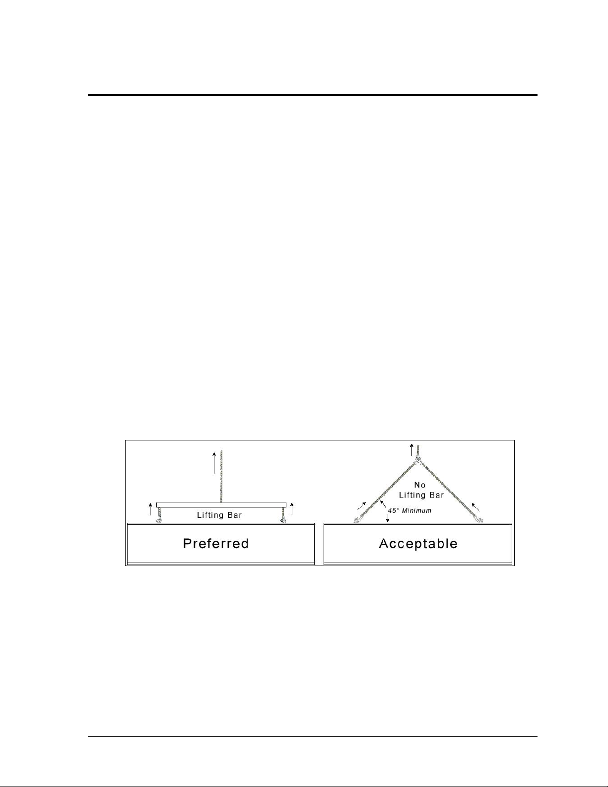
Figure 3: Lifting Methods
Section 2: Mechanical Installation
Mechanical installation consists of installing concrete footing and steel beams and mounting the
scoreboard and accompanying ad panels to the beams. The product specification sheets listed in
Appendix A include installation specification drawings that show the recommended number of
beams and spacing between them. The drawings also indicate the size of beams required to support
the scoreboard at different heights and at various wind speeds.
The column and footing size dimensions are to assist with estimating installation costs. They are
estimates only and are not intended for actual construction purposes. Be sure that the installation
complies with local building codes and is suitable for the particular soil and wind conditions. The
columns, footings, and all connection details must be designed and certified by a professional
engineer licensed to practice in the state of the scoreboard installation.
Note: Daktronics does not assume any liability for any installation derived from the information
provided in this manual or installations designed and installed by others.
2.1 Lifting the Scoreboard
Larger scoreboard sections and message centers are shipped equipped with eyebolts used to
lift them. The eyebolts are located along the top of the cabinet for each scoreboard or
scoreboard section. Daktronics scoreboards use 1/2" and 5/8" shoulder-type eyebolts mounted
to the top of each scoreboard section.
Daktronics strongly recommends using a spreader bar, or lifting bar, to lift the display.
Spreader bars ensure the force on the eyebolts remains straight up, minimizing lifting stress.
Figure 3 illustrates the preferred scoreboard lifting method on the left and an acceptable
alternative lifting method on the right. When lifting the display:
Use a spreader bar if possible.
Use every lifting point provided.
Cables and chains attached to the eyebolts and directly to a center lifting point, as shown in
the right-hand example in Figure 3, can create a dangerous lateral force on the eyebolts and
may cause the eyebolts to fail. The smaller the angle between the cable and the top of the
display, the lighter the sign must be to safely lift it. If this method must be used, ensure a
minimum angle between the chain and scoreboard of at least 45°.
Mechanical Installation 3
Page 10
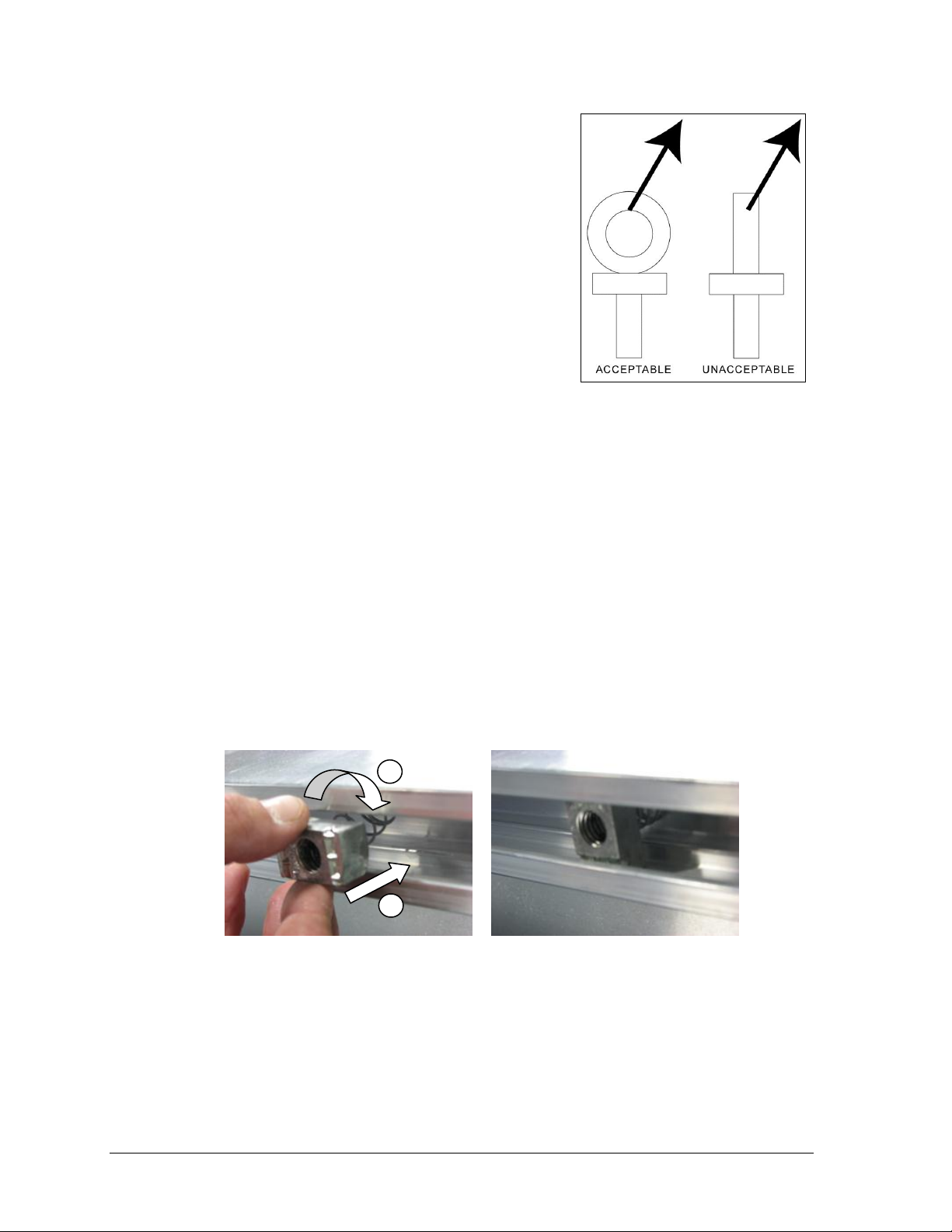
Figure 4: Eyebolt Plane Load
1) Insert into channel 2) Twist Correct spring nut position
Figure 5: Spring Nut Insertion
1
2
Do NOT attempt to lift the display if the angle is less than
45°. Exceeding load angles or weight limits could cause
the bolts in the scoreboard cabinet to buckle, resulting in
serious damage to the scoreboard or injury to personnel.
Also, loads should be applied directly in the plane of the
eyebolt as shown in Figure 4.
Note: Daktronics assumes no liability for damages
resulting from incorrect setup or lifting methods.
Eyebolts are intended for lifting only. Do not attempt
to permanently support the display by the eyebolts.
In typical multi-section installations, the lower scoreboard
is installed first and secured to the support beams.
The upper section is then placed atop or above the lower
section and attached to the beams. Refer to Section 3.5 for
more information on the power/signal connections between sections.
If installers remove the eyebolts, plug the holes with bolts and the rubber washers that are
used with the eyebolts. Apply silicone or another waterproof sealant to the eyebolt openings.
Also inspect the top and sides of the display for any other holes or openings that may allow
moisture to enter the display and plug and seal those openings.
2.2 Scoreboard Mounting
Two standard mounting methods are available for Daktronics outdoor scoreboards.
Both methods require spring nuts to be inserted into the rear channel of the scoreboard:
1. Insert spring nuts into the top and bottom scoreboard channels. Twist the spring nuts
until they are perpendicular to the scoreboard channel (Figure 5).
Note: Each scoreboard section require four spring nuts per beam (two at the top and two
at the bottom).
2. Measure the beam spacing and position a spring nut on either side of the beams.
Once the spring nuts are in place, refer to the appropriate section below for the type of
mounting hardware provided with the scoreboard.
4 Mechanical Installation
Page 11
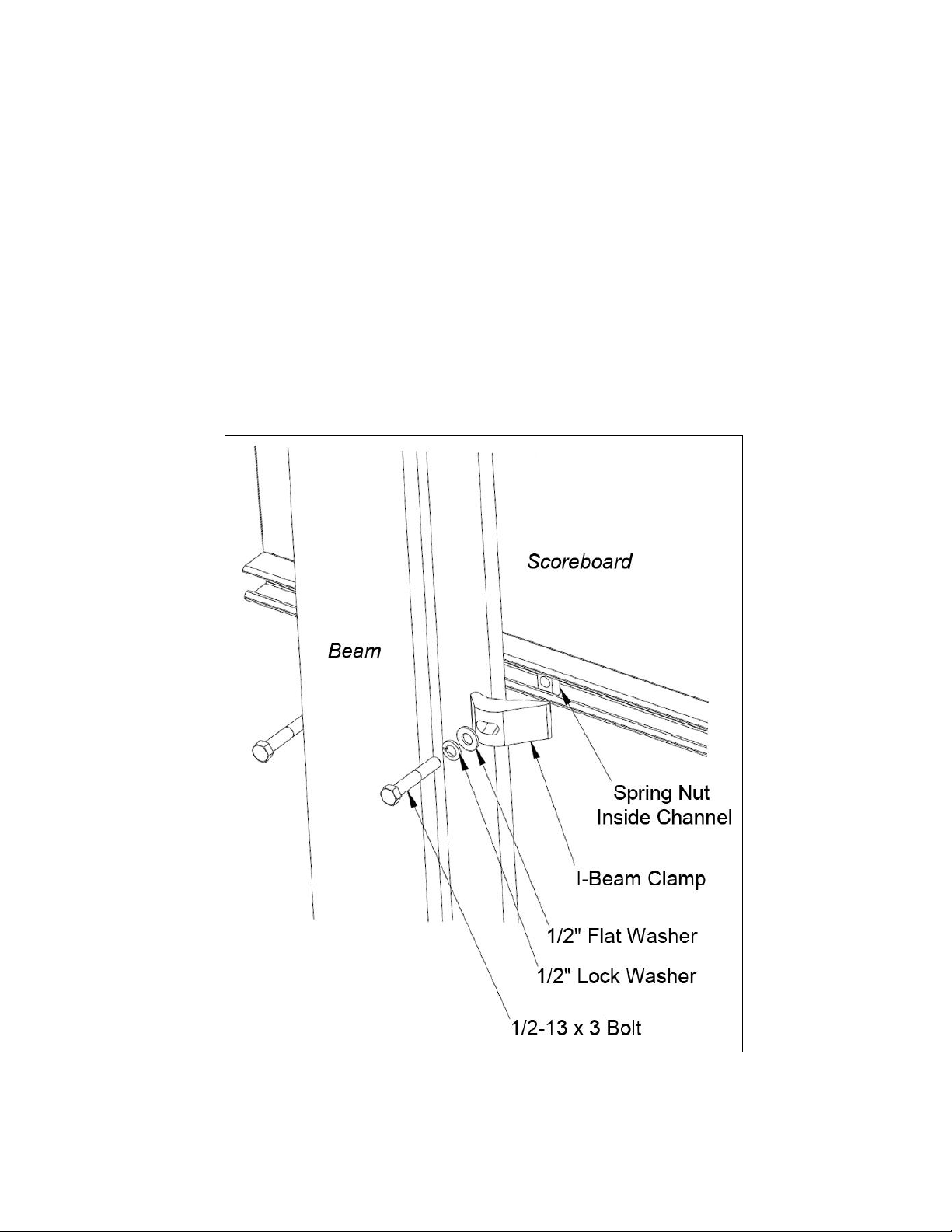
Figure 6: I-beam Clamp Mounting Method, Rear Isometric View
I-Beam Clamps
This mounting method is used to mount a scoreboard to I-beams with a flange thickness of
1
/4" – 3/4". If flange thickness is greater than 3/4", longer bolts will be required at additional
expense.
Mounting hardware includes I-beam clamps, 1/2-13 x 3" bolts, 1/2" flat washers, and 1/2" lock
washers. Refer to Figure 6 and Drawing A-1052565 in Appendix B.
1. Position a scoreboard section at the front of the beams, and lift it to the desired height.
2. Slide a lock washer, flat washer, and I-beam clamp onto the bolt, and loosely screw
the bolt into the spring nut.
3. Position each I-beam clamp assembly as close to the I-beam flanges as possible.
4. Make final adjustments in the positioning of the scoreboard section to ensure it is
flush and level, and firmly tighten all of the bolts.
5. Repeat steps 1-4 with all scoreboard sections.
Note: For four-section scoreboards mounting to three beams, mounting straps are
required along the middle beam to join the horizontal scoreboard sections together.
Refer to Drawing A-1115341 in Appendix B for more information.
Mechanical Installation 5
Page 12
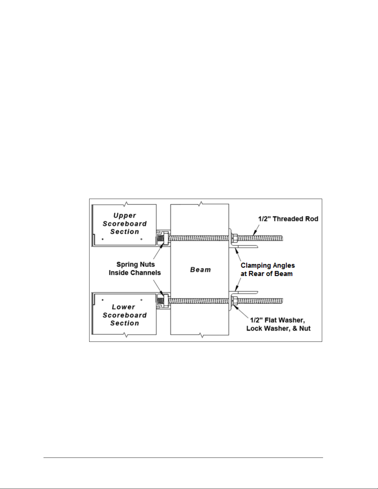
Figure 7: Clamping Angle Mounting Method, Side View
Clamping Angles
This mounting method may be used to mount a scoreboard to I-beams or any beam/pole that
does not have flanges.
Mounting hardware includes rear clamping angles; 1/2-13 x 24" threaded rods; and 1/2" nuts,
flat washers, and lock washers. Refer to Figure 7 and Drawing A-1048184 in Appendix B.
Note: The threaded rods do not pass through the beams; they run along both sides.
1. Screw a threaded rod into each of the spring nuts as far as it will go.
2. Position a scoreboard section at the front of the beams with the threaded rods
extending from the rear of the spring nuts, straddling the beams.
3. Lift the scoreboard section to the desired height.
4. Slide clamping angles over the ends of the rods and loosely install the washers and
nuts.
5. Make final adjustments in the positioning of the scoreboard section to ensure it is
flush and level, and firmly tighten all of the 1/2" hex nuts.
6. Repeat steps 1-5 for all scoreboard sections.
6 Mechanical Installation
Page 13
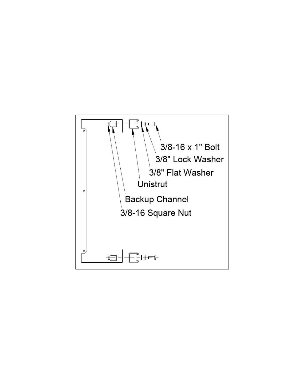
Figure 8: Unistrut Attachment, Side View
2.3 Ad Panel Mounting
Unistrut Attachment
1. Using the backup channel as a template, drill four
rear flanges of the ad panel where the beams will be located.
Note: Try to ensure that the two center holes will be within the width of the beam.
2. If the ad panel has backsheets, remove them as needed to access the ad panel interior.
3. Attach the piece of unistrut to the ad panel with the included hardware, as shown in
Figure 8.
7
/16" holes in the upper and lower
4. If any backsheets were removed, put them back on at this time.
5. Place spring nuts into the unistrut. Twist the spring nuts until they are perpendicular
to the unistrut channel (refer to Figure 5 from Section 2.2).
Once the unistrut is attached and the spring nuts are in place, refer to the appropriate section
below for the type of mounting hardware provided with the ad panel.
Mechanical Installation 7
Page 14
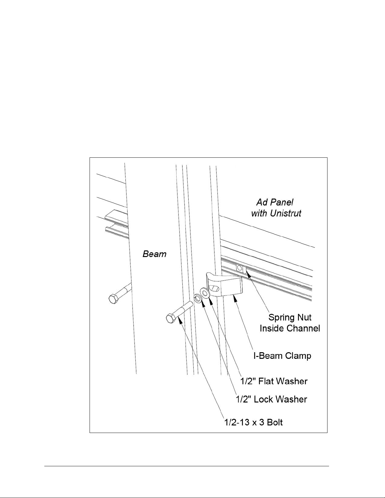
Figure 9: Ad Panel Mounting with I-beam Clamps, Rear Isometric View
I-Beam Clamps
Mounting hardware includes I-beam clamps, 1/2-13 x 3" bolts, 1/2" flat washers, and 1/2" lock
washers. Refer to Figure 9 and Drawing A-1052539 in Appendix B.
Note: I-beams must have a flange thickness of 1/4" – 3/4". If flange thickness is greater
than 3/4", longer bolts will be required at added expense.
1. Position the ad panel at the front of the beams, and lift it to the desired height.
2. Slide a lock washer, flat washer, and I-beam clamp onto the bolt, and loosely screw
the bolt into the spring nut.
3. Position each I-beam clamp assembly as close to the I-beam flanges as possible.
4. Make final adjustments in the positioning of the ad panel to ensure it is flush and
level, and firmly tighten all of the bolts.
8 Mechanical Installation
Page 15

Figure 10: Ad Panel Mounting with Clamping Angles, Side View
Clamping Angles
Mounting hardware includes rear clamping angles; 1/2-13 x 24" threaded rods; and 1/2" nuts,
flat washers, and lock washers. Refer to Figure 10 and Drawing A-1052388 in Appendix B.
Note: The threaded rods do not pass through the beams; they run along both sides.
1. Screw a threaded rod into each of the spring nuts as far as it will go.
2. Position the ad panel at the front of the beams, and lift it to the desired height.
3. Slide clamping angles over the ends of the rods and loosely install the washers
and nuts.
4. Make final adjustments in the positioning of the ad panel to ensure it is flush and
level, and firmly tighten all of the 1/2" hex nuts.
2.4 Scoreboard Protective Devices
Daktronics makes optional protective devices, including screens and netting, to help prevent
damage to the scoreboard due to normal ball impacts.
Note: Some users install devices to protect the scoreboard from projectiles. Scoreboard
protection devices not provided by Daktronics must be approved by Daktronics prior to
installation. Failure to follow this approval procedure will void the scoreboard warranty.
Mechanical Installation 9
Page 16

Page 17

Figure 11: Wired Installation Example
Section 3: Electrical Installation
CAUTION: Only qualified individuals should terminate power and signal cable and access the
electrical components of the display and its associated equipment. It is the responsibility of the
electrical contractor to ensure that all electrical work meets or exceeds local and national codes.
Daktronics engineering staff must approve all changes or the warranty will be void.
3.1 Installation Overview
The diagram shown in Figure 11 illustrates a typical wired setup between a multi-section
outdoor scoreboard and controller. Daktronics part numbers are shown in parentheses.
Electrical Installation 11
Page 18

Figure 12: Wireless Installation Example
The diagram shown in Figure 12 illustrates a typical wireless setup between a multi-section
outdoor scoreboard and controller.
3.2 Power
Correct power installation is imperative for proper display operation. The subsections that
follow give details of display power installation. Only qualified individuals should attempt to
complete the electrical installation; untrained personnel should not attempt to install these
displays or any of the electrical components. Improper installation could result in serious
damage to the equipment or injury to personnel.
Multi-section outdoor scoreboards require a dedicated 120 V (or 240 V for international use)
circuit for incoming power (refer to Appendix A). The display itself has no breakers or fuses.
WARNING: It is critical that 120 V scoreboard circuits be fused at 20 A and that all
conductors used must be designed to pass a 20 A current in normal operation. For 240 V
scoreboards, consult local electrical codes. Failure to meet wiring and overcurrent
protection device requirements will void the scoreboard warranty.
12 Electrical Installation
Page 19

Figure 13: Power Warning Label
Grounding
The display must be properly grounded according to local and national codes or the warranty
will be void. Proper grounding is necessary for reliable equipment operation and protects the
equipment from damaging destructive disturbances and lightning.
Daktronics recommends a resistance-to-ground of 10 ohms or less. The electrical contractor
performing the electrical installation can verify ground resistance. Daktronics Sales and
Service personnel can also provide this service.
The display system must be earth-ground. The material for an earth-ground electrode differs
from region to region and may vary according to conditions present at the site. Consult local
and national electrical codes.
Daktronics does not recommend using the support structure as an earth-ground electrode;
concrete, primer, corrosion, and other factors make the support structure a poor ground.
Note: The support structure may be used as an earth-ground electrode only if designed to
do so. A qualified inspector must approve the support structure and grounding methods.
There are two types of power installation: installation with ground and neutral conductors
provided, and installation with only a neutral conductor provided. These two power
installations differ slightly, as described in the following paragraphs:
Installation with Ground and Neutral Conductors Provided
For this type of installation, the power circuit must contain an isolated earth-ground
conductor. In this circumstance, do not connect neutral to ground at the disconnect or at the
display as this would violate electrical codes and void the warranty.
Use a disconnect so that all ungrounded lines can be disconnected. The National Electrical
Code requires the use of a lockable power disconnect within sight of or at the display.
Installation with Only a Neutral Conductor Provided
Installations where no grounding conductor is provided must comply with Article 250-32 of
the National Electrical Code. If the installation in question meets all of the requirements of
Article 250-32, the following guidelines must be observed:
Connect the grounding electrode cable at the local disconnect, never at the display
driver/power enclosure.
Use a disconnect that opens all of the ungrounded phase conductors.
Connection
Both power and signal cables are routed into the scoreboard from the rear via separate
conduits. All power and signal wiring terminates at the master driver enclosure. Note that
systems with radio control do not require external signal wiring.
Look for a warning label similar to Figure 13 to locate the
front access panel to the driver enclosure. Remove the screws
or loosen the latches to open the access door panel. Remove
the metal cover of the driver enclosure to expose the driver
components (Figure 14).
Electrical Installation 13
Page 20

Figure 14: Driver Enclosure & Power Terminal Block
Figure 15: Digit Segment POST
Refer to the component location drawings attached to the product specification sheets listed
in Appendix A for precise power/signal termination location for each model.
Connect the appropriate wires coming through the rear of the scoreboard to the main
terminal block, as shown in Figure 14. Note that SIGNAL OUT connects here as well.
Note: If a power receptacle is needed to operate the control console at the scoreboard for
troubleshooting, Daktronics recommends that an installation electrician provides a 120 V
outlet close to the disconnect box specifically for this purpose.
3.3 Power-On Self-Test (POST)
The scoreboard performs a self-test each time that power is turned on and the control console
is powered off or not attached to the scoreboard. If the control console is attached and
powered on, the self-test does not run, and data from the control console is displayed on the
scoreboard after a brief period of time. Each scoreboard self-test pattern will vary depending
on the scoreboard model, the number of drivers and types of digits. Figure 15 shows an
example of the LED bar test pattern that each digit performs.
14 Electrical Installation
Page 21

Figure 16: Radio Settings (Clock)
Figure 17: Radio Settings (Console)
Figure 18: Signal Surge Arrestor Card
Figure 19: Driver Fiber
Connection Location
RA DI O S ETT I NGS
BC AST 1 CH AN 0 1
Radio Settings
If a radio receiver is installed (see
Section 5.3), the radio Broadcast
settings (“b1”) and Channel settings
(“C1”) will be displayed in the clock
digits or Home and Guest scores
during the POST (Figure 16). These
values must match the settings in the
control console (refer to Figure 17 and
the manual listed in Section 1.1).
3.4 Signal Connection
For wired setups, route signal cable through
the conduit knockout on the rear of the
scoreboard to the signal surge arrestor card
(Figure 18), located just above the power
termination block in the driver enclosure.
At the SIGNAL IN terminal block, connect red
signal wire to positive (+) and black signal wire
to negative (–).
Note: Be sure to properly connect the
shield (silver) wire to the SHIELD terminal.
To connect signal to auxiliary displays, such as delay of game clocks, route signal wire from
SIGNAL OUT on the main terminal block (Figure 14) of the primary scoreboard to SIGNAL IN
on the signal card of the auxiliary scoreboard.
For signal cable, Daktronics recommends, as a minimum, single-pair, shielded cable, 22 AWG
(part # W-1077). Two-pair shielded cable (part # W-1234) is preferred.
Fiber Optic
Another common signal communication method is fiber optic
cabling. A minimum cabling of multi-mode, 62.5/125 um, and
2-core fiber cable is recommended (part # W-1242). The fiber optic
cable is terminated to a male ST-type connector and plugged into
the mating J26 FIBER jack on the driver (Figure 19). This method
requires a signal converter between the All Sport console’s
scoreboard output and the fiber optic cable (not provided by
Daktronics).
Electrical Installation 15
Page 22

Figure 20: Power/Signal Connection – Two Sections, Excluding BA (Front View)
Multiple Driver Connections
Some models in the multi-section outdoor scoreboard line require multiple drivers in each
scoreboard section and use a master/slave driver system. Master and slave drivers function
identically, but slave units lack the power termination block and signal surge suppression
card. When one section has multiple drivers, they simply plug into one another, and this is
done at the factory. Drivers between sections, however, require additional on-site connection
as described in Section 3.5.
Note: Scoreboards capable of displaying speed of pitch (SOP) have an additional master
driver. These models also require a separate signal connection (either wired or radio)
from a dedicated speed of pitch All Sport 5000 console. Refer to the Baseball Speed of
Pitch Systems Configuration Manual (ED-12224), available online at
www.daktronics.com/manuals, for more information about setting up an SOP system.
3.5 Power/Signal Connections Between Sections
Refer to the component location drawings attached to the product specification sheets listed
in Appendix A for exact driver locations when connecting multiple scoreboard sections.
Two-Section Models
Open the appropriate access panel on the bottom section to locate the coiled bundle of
interconnect cable coming from the driver, then route and connect the cables as described
below and shown in Figure 20.
Note: Additional panels may be opened for easier access when routing the cable.
Route the 5-pin interconnect cable from the Bottom Section up into the Top Section, and
connect the J43 jack to the P43 plug.
Note: In the MS-2009 and FB-3010, the top section driver is A2. In the MS-2918, the top
section driver is A3.
For the FB-3010, MS-2009, SO-2011, and SO-2043 only, route the interconnect cable from
the Top Section down into the Bottom Section, and connect the P42 plug to the J42 jack.
For the BA-2025 and BA-2027, route the 5-pin interconnect cable from the Bottom
Section up into the Top Section, and connect the P42 plug to the J42 jack (Figure 21).
16 Electrical Installation
Page 23

Figure 21: Power/Signal Connection – Two Sections, BA-2025 & BA-2027 (Front View)
Figure 22: Power/Signal Connection – Four Sections, BA-2026 & BA-2028 (Front View)
For the BA-1518 with red/amber digits, there are five 9-pin digit harnesses (P1–P4 &
P15) in the upper section that must be routed down into the bottom section and
plugged into the mating jacks (J1–J4 & J15) on the A1 driver. For the BA-1518 with
white digits, there is a single 5-pin interconnect cable coiled in the upper section that
must be routed down into the bottom section and connected to the J42B jack on a Ycable coming from the A2 driver.
Four-Section Models
BA-2026 & BA-2028
Open the appropriate access panel on the bottom-left cabinet (Section C) to locate the coiled
bundles of interconnect cable coming from the driver, then route and connect the cables as
described below and shown in Figure 22.
Note: Additional panels may be opened for easier access when routing the cable.
1. There are four 9-pin digit harnesses (P8–P11) in the upper-right cabinet (Section B)
that must be routed into the upper-left cabinet (Section A) and connected to the mating
J8–J11 jacks on the A1 driver. For scoreboards with white digits, 2-pin cables must also
be routed and connected to the mating J8–J11 jacks on the PS1 power supply.
2. There are also two separate interconnect cables in Section C:
a. Route the 5-pin interconnect cable with the P42 plug up into Section A, and
connect it to the J42 jack on the A1 driver.
b. Route the 5-pin interconnect cable with the J43 jack over into the bottom-right
cabinet (Section D), and connect it to another interconnect cable with the P42 plug.
Electrical Installation 17
Page 24

Figure 23: Power/Signal Connection – Four Sections, BA-2029 (Front View)
BA-2029
Open the appropriate access panel on the bottom-left cabinet (Section C) to locate the coiled
bundles of interconnect cable coming from the driver, then route and connect the cables as
described below and shown in Figure 23.
Note: Additional panels may be opened for easier access when routing the cable.
1. There are seven 9-pin digit harnesses (P1–P7) in the upper-left cabinet (Section A)
that must be routed into the upper-right cabinet (Section B) and connected to the
mating J1–J7 jacks on the A1 driver. For scoreboards with white digits, 2-pin cables
must also be routed and connected to the mating J1–J7 jacks on the PS1 power supply.
2. There are two separate interconnect cables in Section C:
a. Route the 5-pin interconnect cable with the P42 plug up into Section A first then
over into Section B, and connect it to the J42 jack on the A1 driver.
b. Route the 5-pin interconnect cable with the J43 jack over into the bottom-right
cabinet (Section D), and connect it to another interconnect cable with the P42 plug.
FB-2028
Open the appropriate access panels on the upper-left (Section A) and bottom-left cabinet
(Section C) to locate the coiled bundles of interconnect cable coming from the drivers.
Refer to Figure 24.
Note: Additional panels may be opened for easier access when routing the cable.
1. Route the 5-pin interconnect cable with the J43 jack from Section C over into the
bottom-right cabinet (Section D) and connect it to the P43 plug on the A4 driver.
2. There will also be two separate interconnect cables in Section A:
a. Route the 5-pin interconnect cable with the J43 jack over into the upper-right
cabinet (Section B) and connect it to the P42 plug on another interconnect cable
coming from the A2 driver.
b. Route the 5-pin (two wire, signal only) cable with the P42 plug down into Section
C, and connect it to the J42A jack on a Y-cable coming from the A3 driver.
Note: The FB-2028 can be thought of as two scoreboards stacked on top of each other.
Both the A1 and A3 drivers require power termination, while only A3 requires signal
termination from the control location. Refer to Section 3.2 and Section 3.4.
18 Electrical Installation
Page 25

Figure 24: Power/Signal Connection – FB-2028 (Front View)
3.6 Lightning Protection
The use of a disconnect near the scoreboard to completely cut all current-carrying lines
significantly protects the circuits against lightning damage. In order for this system to
provide protection, the power must be disconnected when the scoreboard is not in use.
The control console should also be disconnected from power and from the signal junction box
when the system is not in use. The same surges that may damage the scoreboard’s driver can
also damage the console’s circuitry.
Electrical Installation 19
Page 26

Page 27

Market Description
Customer Service Number
Schools (including community/junior colleges), religious
organizations, municipal clubs and community centers
877-605-1115
Universities and professional sporting events, live events
for auditoriums and arenas
866-343-6018
Section 4: Daktronics Exchange and Repair &
Return Programs
4.1 Exchange Program
The Daktronics Exchange Program is a service for quickly replacing key components in need
of repair. If a component fails, Daktronics sends a replacement part to the customer who, in
turn, returns the failed component to Daktronics. This decreases equipment downtime.
Customers who follow the program guidelines explained below will receive this service.
Before Contacting Daktronics
Identify these important numbers:
Display Assembly Number: ______________________________________________________
Display Model Number: _________________________________________________________
Job/Contract Number: __________________________________________________________
Date Manufactured/Installed: ___________________________________________________
Daktronics Customer ID Number: ________________________________________________
To participate in the Exchange Program, follow these steps:
1. Call Daktronics Customer Service.
2. When the exchange part is received, mail the old part to Daktronics.
If the replacement part fixes the problem, send in the problem part being replaced.
a. Package the old part in the same shipping materials in which the replacement
part arrived.
b. Fill out and attach the enclosed UPS shipping document.
c. Ship the part to Daktronics.
3. The defective or unused parts must be returned to Daktronics within 5 weeks of
initial order shipment.
If any part is not returned within five (5) weeks, a non-refundable invoice will be
presented to the customer for the costs of replenishing the exchange parts inventory
with a new part.
Daktronics reserves the right to refuse parts that have been damaged due to acts of
nature or causes other than normal wear and tear.
Daktronics Exchange and Repair & Return Programs 21
Page 28

4.2 Repair & Return Program
For items not subject to exchange, Daktronics offers a Repair & Return Program. To send a
part for repair, follow these steps:
1. Call or fax Daktronics Customer Service:
Refer to the appropriate market phone number in the chart on the previous page.
Fax: 605-697-4444
2. Receive a case number before shipping.
This expedites repair of the part.
3. Package and pad the item carefully to prevent damage during shipment.
Electronic components, such as printed circuit boards, should be placed in an
antistatic bag before boxing. Daktronics does not recommend using packing ‘peanuts’
when shipping.
4. Enclose:
name
address
phone number
the case number
a clear description of symptoms
Shipping Address
Daktronics Customer Service
[Case #]
201 Daktronics Drive, Dock E
Brookings, SD 57006
4.3 Daktronics Warranty and Limitation of Liability
The Daktronics Warranty and Limitation of Liability is located in Appendix C. The Warranty
is independent of Extended Service agreements and is the authority in matters of service,
repair, and display operation.
22 Daktronics Exchange and Repair & Return Programs
Page 29

Section 5: Scoreboard Options
5.1 Team Name Message Centers (TNMCs)
Team Name Message Centers (TNMCs) are programmable LED displays that allow users to
show custom Home and Guest names. TNMCs are typically ordered factory-installed but can
be field-mounted after the scoreboard is in place.
For more information about TNMCs, contact a Daktronics representative or refer to the
service manual listed in Section 1.2.
5.2 Trumpet Horns
Trumpet horn options are available for installation only on scoreboards that have clocks.
There are two types of optional trumpet horns:
Internally mounted 120 V trumpet horn
Externally mounted 12 VDC trumpet horn
A 120 V trumpet horn cannot be installed on a 240 V model scoreboard. For more information
about trumpet horns, contact a Daktronics representative or refer to the Trumpet Horn
Installation Manual (ED-10006), available online at www.daktronics.com/manuals.
5.3 Radio Control
Radio control is an option for all Daktronics outdoor LED scoreboards. The system provides
scoreboard control via a 2.4 GHz, extra-high frequency FM signal.
The radio transmitter and receiver are not standard. This setup requires a control console
equipped with radio output as well as a radio receiver plugged into the primary driver and
mounted internally to the front panel of the scoreboard.
For additional information about this option, contact a Daktronics representative; for
complete information on setting up radio communication control, refer to the Gen V Radio
Installation Manual (ED-13831) or the Gen VI Radio Installation Manual (DD2362277),
both available online at www.daktronics.com/manuals.
5.4 Time Outs Left (T.O.L) Digits
Certain scoreboards have the option to add a time outs left (TOL) digit for both the home and
guest teams. These digits are installed by simply unscrewing the blank face panel, connecting
and securing the digit panel, and manually applying the “T.O.L.” vinyl caption.
The following scoreboard models in this manual have optional T.O.L. digits:
15" tall digits - FB-2018, FB-2019, FB-2020
18" tall digits - FB-2021, FB-2022
Scoreboard Options 23
Page 30

Figure 25: Changing Scoreboard Captions
5.5 Changeable Caption Kits
Caption kits contain hardware for one caption
only and consist of an upper caption retainer,
a lower caption retainer, a changeable caption
panel and screws.
The standard HOME and GUEST captions
are applied directly to the face of the
scoreboard. Team name captions are on
changeable panels that fit into retainers
mounted above and below the HOME and
GUEST captions. If these retainers are not
already present, attach the retainers included
with the caption kit.
Other caption kits are available to show
different information for different sports.
To install a changeable panel:
1. Insert the screws on the caption changing pole (Daktronics part # 0F-1091-0099) into
the keyholes on the panel.
2. Lift the panel all the way up into the upper retainer and then insert the bottom of the
panel into the lower retainer (Figure 25).
3. Take the screws on the caption changing pole out of the keyholes.
Reverse this procedure to remove the caption panel.
The caption changer pole is extendable. Loosen the ring tightener and extend the pole to the
desired length, and then tighten the ring before lifting the caption.
CAUTION: The aluminum caption changer can conduct electricity. Do not use it within
20-feet of power lines. Also be careful when using the caption changer in high or gusting
winds. Wind may catch the panel and unhook it from the changer or make it difficult to
maintain a grip on the pole. Hold the pole tightly in windy conditions.
24 Scoreboard Options
Page 31

Model
Spec Sheet
Model
Spec Sheet
Model
Spec Sheet
BA-1518
DD2118098
FB-2021
DD2167297
MS-2009
DD2167425
BA-2025
DD1969963
FB-2022
DD2167302
MS-2918
DD2167437
BA-2026
DD1972163
FB-2023
DD2167306
SO-2011
DD2167461
BA-2027
DD1972393
FB-2024
DD2167351
SO-2018
DD2167482
BA-2028
DD1972415
FB-2025
DD2167356
SO-2019
DD2167485
BA-2029
DD1972427
FB-2026
DD2167363
SO-2021
DD2167495
FB-2018
DD2167274
FB-2027
DD2167369
SO-2023
DD2167513
FB-2019
DD2167276
FB-2028
DD1972444
SO-2043
DD1956444
FB-2020
DD2167285
FB-3010
DD2196899
Appendix A: Specifications
All of the product specification sheets for the scoreboards in this manual are listed below.
Product-specific installation and component location drawings are included with each spec sheet.
Note: Refer to Figure 1 to determine a scoreboard’s model number.
Viewing Product Specifications Online
If a specification sheet is incorrect or missing, they are all available for download online.
When viewing the digital version of this manual, simply click a link above to open it.
When referencing the printed version of this manual, open an Internet browser and go to
http://www.daktronics.com/Web%20Documents/HSPR-Documents/DD#######.pdf
(replace “DD#######” with one of the Spec Sheet numbers shown above).
Specifications 25
Page 32

Model &
Options
Watts
Amps
120 / 240 VAC
BA-1518
450
3.8 / 1.9
TNMCs
750
6.3 / 3.1
BA-2025
850
7.1 / 3.5
TNMCs
1150
9.6 / 4.8
BA-2026
1200
10 / 5
TNMCs
1800
15 / 7.5
BA-2027
850
7.1 / 3.5
TNMCs
1150
9.6 / 4.8
BA-2028
1250
10.4 / 5.2
TNMCs
1850
15.4 / 7.7
BA-2029
1400
11.6 / 5.8
TNMCs
1920
16 / 8
FB-2018
FB-2019
FB-2020
750
6.3 / 3.1
TNMCs
1050
8.8 / 4.4
All Electronic
1650
13.8 / 6.9
All Backlit
1650
13.8 (120 only)
FB-2021
FB-2022
FB-2023
800
6.7 / 3.3
TNMCs
1400
11.7 / 5.8
All Electronic
1920
16 / 8
All Backlit
1820
15.2 (120 only)
FB-2024
FB-2025
FB-2026
FB-2027
800
6.7 / 3.3
TNMCs
1400
11.7 / 5.8
All Electronic
1920
16 / 8
All Backlit
1920
16 (120 only)
Model &
Options
Watts
Amps
120 / 240 VAC
FB-2028
Top: 850
Bottom: 350
Top: 7.1 / 3.5
Bottom: 2.9 / 1.5
TNMCs
Top: 1450
Bottom: 350
Top: 12.1 / 6
Bottom: 2.9 / 1.5
All Electronic
Top: 1450
Bottom: 1250
Top: 12.1 / 6
Bottom: 10.4 / 5.2
All Backlit
Top: 1390
Bottom: 1790
Top: 11.6
Bottom: 14.9
(120 only)
FB-3010
650
5.4 / 2.7
TNMCs
950
7.9 / 4
MS-2009
1000
8.3 / 4.2
TNMCs
1600
13.3 / 6.7
All Electronic
1920
16 / 8
All Backlit
1920
16 (120 only)
SO-2011
750
6.3 / 3.1
TNMCs
1350 W
11.3 / 5.6
SO-2018
SO-2019
700
5.8 / 2.9
TNMCs
1000
8..3 / 4.2
All Electronic
1600
13.3 / 6.7
All Backlit
1600
13.3 (120 only)
SO-2021
SO-2023
800
6.7 / 3.3
TNMCs
1400
11.7 / 5.8
All Electronic
1920
16 / 8
All Backlit
1820
15.2 (120 only)
SO-2043
800 W
6.7 / 3.3
TNMCs
1400 W
11.7 / 5.8
Note that the following scoreboards have different power specifications with white digits. They may
also have different component location drawings, located in the Service Manual (refer to Section 1.2).
26 Specifications
Page 33

Appendix B: Reference Drawings
Drawing Title Drawing Number
P1647; Pole Mounting Options ............................................................................................... A-1048184
Ad Panel Pole Mounting ......................................................................................................... B-1052388
Ad Panel I-beam Clamp Mounting .......................................................................................... B-1052539
P1647; I-beam Clamp Mounting ............................................................................................. A-1052565
Mtg Straps, 4 Sec SCBD on 3 Poles ...................................................................................... A-1115341
Reference Drawings 27
Page 34

Page 35

SCOREBOARD
VERTICAL BEAM
SPRING NUT
REAR MOUNTING ANGLE
1/2" THREADED ROD
1/2" FLAT WASHER,
LOCK WASHER, AND NUT
SIDE VIEW
1/2" THREADED ROD
1/2" FLAT WASHER
LOCK WASHER, AND NUT
REAR MOUNTING ANGLE
REV
REV
REV
VERTICAL BEAM
SPRING NUT
DISPLAY
***CRITICAL***
MAKE SURE SPRING NUT
IS TURNED TO VERTICAL
POSITION INSIDE
SCOREBOARD CHANNEL
FRONT OF DISPLAY
TOP VIEW
SCALE 1/10
STRUCTURAL NOTES:
EXTRA THREADED ROD
CAN BE CUT OFF
- BOLT TORQUE: 30 FT-LB
NOTES:
REAR ISOMETRIC VIEW
DATE:
03
3 JULY 13
DATE:
02
20 SEP 12
DATE:
01
06 OCT 11
ADDED STRUCTURAL NOTE BY:
REMOVED CHAMFER FROM 0M-133259
PER EC-7114
REPLACED VERTICAL I-BEAM
WITH 6" X 6" SQUARE TUBE
TTF
BY:
LMG
BY:
JAVA
- THREADED RODS RUN ALONG BOTH SIDES OF BEAM
- RODS DO NOT PASS THROUGH THE FLANGES OF THE BEAM
- NO DRILLING NECESSARY
- MAKE SURE SPRING NUT IS PERPENDICULAR TO CHANNEL
OPENING ON SCOREBOARD
DAKTRONICS, INC.
BROOKINGS, SD 57006
PROJ:
TITLE:
DESIGN:
SCALE:
DO NOT SCALE DRAWING
OUTDOOR SCOREBOARDS
P1647; POLE MOUNTING OPTIONS
DOPPELT
1/5
SHEET: REV JOB NO:
DRAWN:
THE CONCEPTS EXPRESSED AND DETAILS SHOWN ON
THIS DRAWING ARE CONFIDENTIAL AND PROPRIETARY.
DO NOT REPRODUCE BY ANY MEANS WITHOUT THE
EXPRESSED WRITTEN CONSENT OF DAKTRONICS, INC.
COPYRIGHT 2010 DAKTRONICS, INC.
DOPPELT
FUNC-TYPE-SIZE
1 OF 1 03 P1647 E-10-A
DATE:
22 MAR 11
1048184
Page 36

Page 37

Page 38

VERTICAL BEAM - FLANGE THICKNESS MUST BE 1/4" - 3/4"
SCOREBOARD
FRONT OF SCOREBOARD
TOP VIEW
1/2-13 X 3.000 BOLT - BOLT THREAD MUST ENGAGE ENTIRE DEPTH
OF SPRING NUT. BOLT MUST BE TIGHTENED TO 40FT-LB TORQUE
1/2" LOCK WASHER
1/2" FLAT WASHER
I-BEAM CLAMP - ASSURE CLAMP IS TIGHTLY ENGAGED
TO I-BEAM AND NUT
SPRING NUT
STANDARD MOUNTING METHOD
MOUNTING INSTRUCTIONS:
1. PLACE SPRING NUTS INTO SCOREBOARD
CHANNEL IN APPROXIMATE LOCATION OF
VERTICAL BEAMS
2. LIFT SCOREBOARD INTO POSITION
3. MAKE SURE THE 1/2-13 BOLTS ARE AS
CLOSE TO THE I-BEAM FLANGES AS POSSIBLE
4. WHEN SCOREBOARD IS ADJUSTED TO
FINAL DESIRED POSITION, TIGHTEN
BOLTS FIRMLY
5. IF FLANGE THICKNESS IS MORE THAN 3/4"
THICK LONGER BOLTS WILL BE REQUIRED
AT THE CUSTOMER'S EXPENSE.
SHEAR-X
REV04DATE:
6 JAN 14
REV03DATE:
23 OCT 13
REV02DATE:
07 MAR 12
REV01DATE:
21 FEB 12
SHEAR-Y
TENSION
EXPLODED REAR ISOMETRIC VIEW
ADDED ALLOWABLE TENSION
AND SHEAR CAPACITY DETAILS
CHANGED BOLT TORQUE FROM
30 FT-LB TO 40 FT-LB
PER EC-12382
ADDED STADNARD MOUNTING METHOD NOTES
CHANGED ROCKER TO I-BEAM
SPRING NUT
***CRITICAL***
MAKE SURE SPRING NUT
IS TURNED TO VERTICAL
POSITION INSIDE
SCOREBOARD CHANNEL
I-BEAM CLAMP
1/2" FLAT WASHER
1/2" LOCK WASHER
1/2-13 X 3.000 BOLT
BY:
JAVA
BY:
NJM
BY:
KDD
BY:
KDD
PROJ:
TITLE:
DESIGN:
SCALE:
ALLOWABLE CAPACITY PER EACH CLAMP:
SHEAR = 160 LBS
TENSION = 2300 LBS
SHEAR AND TENSION LOAD
DIRECTION ARE AS INDICATED ON
REAR ISOMETRIC VIEW
DAKTRONICS, INC.
BROOKINGS, SD 57006
DO NOT SCALE DRAWING
THE CONCEPTS EXPRESSED AND DETAILS SHOWN ON
THIS DRAWING ARE CONFIDENTIAL AND PROPRIETARY.
DO NOT REPRODUCE BY ANY MEANS WITHOUT THE
EXPRESSED WRITTEN CONSENT OF DAKTRONICS, INC.
COPYRIGHT 2013 DAKTRONICS, INC.
OUTDOOR SCOREBOARD
P1647; I-BEAM CLAMP MOUNTING
MCARSRU
1/8
SHEET: REV JOB NO: FUNC-TYPE-SIZE
DRAWN:
MCARSRU
1 OF 1 04 P 1647 E-07-A
DATE:
1052565
06-JAN-14
Page 39

UPPER
SCOREBOARD
SECTION
LOWER
SCOREBOARD
SECTION
SIDE VIEW
SCALE 1/4
STRAP INSTALLATION PROCEDURE FOR 3 POLE APPLICATION
AFTER CLAMPING ALL FOUR SECTIONS OF THE SCOREBOARD
TO MOUNTING BEAMS, IT IS NECESSARY TO ATTACH THE TWO
BOTTOM SECTIONS TO EACH OTHER AND THE TWO
TOP SECTIONS TO EACH OTHER.
STRAPS ARE REQUIRED AT SPLICE LOCATION FOR BOTH
POLE MOUNTING AND I-BEAM MOUNTING STYLES
THIS IS ACHIEVED USING FOUR MOUNTING STRAPS
(1/8" X 1" X 20" LONG) AND #12 HEX HEADED SCREWS.
POSITION THE MOUNTING STRAPS AS SHOWN ON THIS
DRAWING. ATTACH FOUR SCREWS TO ATTACH EACH STRAP.
2 SCREWS ON EACH SIDE OF THE SPLICE.
ATTACH ONE STRAP TO THE TOP & BOTTOM OF
EACH LEFT & RIGHT SECTION.
FAILURE TO ATTACH THE MOUNTING STRAPS TO
THESE DISPLAY SECTIONS VOIDS ALL WARRANTY
MOUNTING STRAP
BEAM
MOUNTING STRAP
FRONT OF DISPLAYS
TOP VIEW
SCALE 1/8
SCOREBOARD SEAM
ISOMETRIC VIEW
SCALE 1/5
SHOWN WITH OUT I-BEAM
REV DATE: BY:
20" LONG
MOUNTING STRAPS
#12 TEK SCREWS @4 PER STRAP
DAKTRONICS, INC.
BROOKINGS, SD 57006
PROJ:
TITLE:
DESIGN:
SCALE:
DO NOT SCALE DRAWING
OUTDOOR SCOREBOARDS
MTG STRAPS,4 SEC SCBD ON 3 POLES
USER NAME
AS SHOWN
SHEET: REV JOB NO:
DRAWN:
THE CONCEPTS EXPRESSED AND DETAILS SHOWN ON
THIS DRAWING ARE CONFIDENTIAL AND PROPRIETARY.
DO NOT REPRODUCE BY ANY MEANS WITHOUT THE
EXPRESSED WRITTEN CONSENT OF DAKTRONICS, INC.
COPYRIGHT 2011 DAKTRONICS, INC.
DOPPELT
FUNC-TYPE-SIZE
1 OF 1 00 P 1647 E-07-A
DATE:
05-OCT-12
1115341
Page 40

Page 41

Appendix C: Daktronics Warranty and Limitation
of Liability
Daktronics Warranty and Limitation of Liability 29
Page 42

Page 43

Copyright © Daktronics, Inc. SL-02374 Rev 10 02-Mar-2009 Page 1 of 2
DAKTRONICS
WARRANTY AND LIMITATION OF LIABILITY
This Warranty and Limitation of Liability (the “Warranty”) sets forth the warranty provided by Daktronics with respect to the Equipment. By
accepting delivery of the Equipment, Purchaser agrees to be bound by and accept these terms and conditions. All defined terms within
the Warranty shall have the same meaning and definition as provided elsewhere in the Agreement.
DAKTRONICS WILL ONLY BE OBLIGATED TO HONOR THE WARRANTY SET FORTH IN THESE TERMS AND CONDITIONS UPON RECEIPT OF FULL
PAYMENT FOR THE EQUIPMENT.
1. Warranty Coverage
2. Exclusion from Warranty Coverage
A. Daktronics warrants to the original end-user that the Equipment will be free from Defects (as defined below) in materials and
workmanship for a period of one (1) year (the “Warranty Period”). The warranty period shall commence on the earlier of: (i) four
weeks from the date that the equipment leaves Daktronics’ facility; or (ii) Substantial Completion as defined herein. The warranty
period shall expire on the first anniversary of the commencement date.
“Substantial Completion” means the operational availability of the Equipment to the Purchaser in accordance with the
Equipment’s specifications, without regard to punch-list items, or other non-substantial items which do not affect the operation of
the Equipment.
B. Daktronics’ obligation under this Warranty is limited to, at Daktronics’ option, replacing or repairing, any Equipment or part
thereof that is found by Daktronics not to conform to the Equipment’s specifications. Unless otherwise directed by Daktronics,
any defective part or component shall be returned to Daktronics for repair or replacement. Daktronics may, at its option,
provide on-site warranty service. Daktronics shall have a reasonable period of time to make such replacements or repairs and
all labor associated therewith shall be performed during regular working hours. Regular working hours are Monday through
Friday between 8:00 a.m. and 5:00 p.m. at the location where labor is performed, excluding any holidays observed by either
Purchaser or Daktronics.
C. Daktronics shall pay ground transportation charges for the return of any defective component of the Equipment. If returned
Equipment is repaired or replaced under the terms of this warranty, Daktronics will prepay ground transportation charges back to
Purchaser; otherwise, Purchaser shall pay transportation charges to return the Equipment back to the Purchaser. All returns must
be pre-approved by Daktronics before shipment. Daktronics shall not be obligated to pay freight for any unapproved return.
Purchaser shall pay any upgraded or expedited transportation charges.
D. Any replacement parts or Equipment will be new or serviceably used, comparable in function and performance to the
original part or Equipment, and warranted for the remainder of the Warranty Period. Purchasing additional parts or Equipment
from the Seller does not extend this Warranty Period.
E. Defects shall be defined as follows. With regard to the Equipment (excepting LEDs), a “Defect” shall refer to a material
variance from the design specifications that prohibit the Equipment from operating for its intended use. With respect to LEDs,
“Defects” are defined as LED pixels that cease to emit light. The limited warranty provided by Daktronics does not impose any
duty or liability upon Daktronics for partial LED pixel degradation. Nor does the limited warranty provide for the replacement or
installation of communication methods including but not limited to, wire, fiber optic cable, conduit, trenching, or for the purpose
of overcoming local site interference radio equipment substitutions.
THIS LIMITED WARRANTY IS THE ONLY WARRANTY APPLICABLE TO THE EQUIPMENT AND REPLACES ALL OTHER WARRANTIES OR
CONDITIONS, EXPRESS OR IMPLIED, INCLUDING, BUT NOT LIMITED TO, THE IMPLIED WARRANTIES OR CONDITIONS OF
MERCHANTABILITY AND FITNESS FOR A PARTICULAR PURPOSE. SPECIFICALLY, EXCEPT AS PROVIDED HEREIN, THE SELLER
UNDERTAKES NO RESPONSIBILITY FOR THE QUALITY OF THE EQUIPMENT OR THAT THE EQUIPMENT WILL BE FIT FOR ANY PARTICULAR
PURPOSE FOR WHICH PURCHASER MAY BE BUYING THE EQUIPMENT. ANY IMPLIED WARRANTY IS LIMITED IN DURATION TO THE
WARRANTY PERIOD. NO ORAL OR WRITTEN INFORMATION, OR ADVICE GIVEN BY THE COMPANY, ITS AGENTS OR EMPLOYEES,
SHALL CREATE A WARRANTY OR IN ANY WAY INCREASE THE SCOPE OF THIS LIMITED WARRANTY.
THIS LIMITED WARRANTY IS NOT TRANSFERABLE.
The limited warranty provided by Daktronics does not impose any duty or liability upon Daktronics for:
A Any damage occurring, at any time, during shipment of Equipment unless otherwise provided for in the Agreement. When
returning Equipment to Daktronics for repair or replacement, Purchaser assumes all risk of loss or damage, and agrees to use
any shipping containers that might be provided by Daktronics and to ship the Equipment in the manner prescribed by
Daktronics;
B. Any damage caused by the unauthorized adjustment, repair or service of the Equipment by anyone other than personnel of
Daktronics or its authorized repair agents;
Page 44

Copyright © Daktronics, Inc. SL-02374 Rev 10 02-Mar-2009 Page 2 of 2
C. Damage caused by the failure to provide a continuously suitable environment, including, but not limited to: (i) neglect or
misuse, (ii) a failure or sudden surge of electrical power, (iii) improper air conditioning or humidity control, or (iv) any other cause
other than ordinary use;
D. Damage caused by fire, flood, earthquake, water, wind, lightning or other natural disaster, strike, inability to obtain materials
or utilities, war, terrorism, civil disturbance or any other cause beyond Daktronics’ reasonable control;
E. Failure to adjust, repair or replace any item of Equipment if it would be impractical for Daktronics personnel to do so because
of connection of the Equipment by mechanical or electrical means to another device not supplied by Daktronics, or the
existence of general environmental conditions at the site that pose a danger to Daktronics personnel;
F. Any statements made about the product by salesmen, dealers, distributors or agents, unless such statements are in a written
document signed by an officer of Daktronics. Such statements as are not included in a signed writing do not constitute
warranties, shall not be relied upon by Purchaser and are not part of the contract of sale;
G. Any damage arising from the use of Daktronics products in any application other than the commercial and industrial
applications for which they are intended, unless, upon request, such use is specifically approved in writing by Daktronics; or
H. Any performance of preventive maintenance.
3. Limitation of Liability
4. Assignment of Rights
5. Dispute Resolution
6. Governing Law
7. Availability of Extended Service Agreement
Daktronics shall be under no obligation to furnish continued service under this Warranty if alterations are made to the Equipment
without the prior written approval of Daktronics.
It is specifically agreed that the price of the Equipment is based upon the following limitation of liability. In no event shall
Daktronics (including its subsidiaries, affiliates, officers, directors, employees, or agents) be liable for any special, consequential,
incidental or exemplary damages arising out of or in any way connected with the Equipment or otherwise, including but not
limited to damages for lost profits, cost of substitute or replacement equipment, down time, lost data, injury to property or any
damages or sums paid by Purchaser to third parties, even if Daktronics has been advised of the possibility of such damages. The
foregoing limitation of liability shall apply whether any claim is based upon principles of contract, tort or statutory duty, principles
of indemnity or contribution, or otherwise.
In no event shall Daktronics be liable to Purchaser or any other party for loss, damage, or injury of any kind or nature arising out of
or in connection with this Warranty in excess of the purchase price of the Equipment actually delivered to and paid for by the
Purchaser. The Purchaser’s remedy in any dispute under this Warranty shall be ultimately limited to the Purchase Price of the
Equipment to the extent the Purchase Price has been paid.
The Warranty contained herein extends only to the original end-user (which may be the Purchaser) of the Equipment and no
attempt to extend the Warranty to any subsequent user-transferee of the Equipment shall be valid or enforceable without the
express written consent of Daktronics.
Any dispute between the parties will be resolved exclusively and finally by arbitration administered by the American Arbitration
Association (“AAA”) and conducted under its rules, except as otherwise provided below. The arbitration will be conducted
before a single arbitrator. The arbitration shall be held in Brookings, South Dakota. Any decision rendered in such arbitration
proceedings will be final and binding on each of the parties, and judgment may be entered thereon in any court of competent
jurisdiction. This arbitration agreement is made pursuant to a transaction involving interstate commerce, and shall be governed
by the Federal Arbitration Act.
The rights and obligations of the parties under this warranty shall not be governed by the provisions of the United Nations
Convention on Contracts for the International Sales of Goods of 1980. Both parties consent to the application of the laws of the
State of South Dakota to govern, interpret, and enforce all of Purchaser and Daktronics rights, duties, and obligations arising
from, or relating in any manner to, the subject matter of this Warranty, without regard to conflict of law principles.
For Purchaser’s protection, in addition to that afforded by the warranties set forth herein, Purchaser may purchase extended
warranty services to cover the Equipment. The Extended Service Agreement, available from Daktronics, provides for electronic
parts repair and/or on-site labor for an extended period from the date of expiration of this warranty. Alternatively, an Extended
Service Agreement may be purchased in conjunction with this warranty for extended additional services. For further information,
contact Daktronics Customer Service at 1-800-DAKTRONics (1-800-325-8766).
 Loading...