

Daktronics Outdoor LED Scoreboards Service Manual
201 Daktronics Drive PO Box 5128 Brookings, SD 57006-5128
Tel: 1-800-DAKTRONICS (1-800-325-8766) Fax: 605-697-4746
www.daktronics.com/support
Outdoor LED Scoreboards
Service Manual
DD2124597 Rev 6 – 19 December 2014
Single-Section Models
BA-618
BA-2718
RO-2010
BA-624
CR-2002
RO-2011
*
BA-2004
CR-2003
SO-918
BA-2005
FB-824
SO-2008
BA-2010
FB-4005
SO-2013
BA-2014
FB-2030
SO-2918
BA-2017
MS-915
TI-218
BA-2019
MS-918
TI-2003
BA-2022
MS-2002
TI-2010
BA-2023
MS-2004
TI-2012
BA-2024
MS-2006
TI-2015
BA-2030
MS-2012
TI-2019
BA-2515
MS-2024
TI-2024
BA-2518
MS-2025
TI-2032
BA-2618
*
MS-2026
BA-2715
MS-3918
Multi-Section Models
BA-1518
FB-2020
MS-2009
BA-2025
FB-2021
MS-2918
BA-2026
FB-2022
SO-2011
BA-2027
FB-2023
SO-2018
BA-2028
FB-2024
SO-2019
BA-2029
FB-2025
SO-2021
BA-2125
FB-2026
SO-2023
BA-2127
FB-2027
SO-2043
FB-2018
FB-2028
FB-2019
FB-3010
Modular Football Scoreboards
FB-2500 Series
FB-2600 Series
* Discontinued
Tennis Models
TN-2601
TN-2650
TN-2603
TN-2651
TN-2604
TN-2652
TN-2605
TN-2653
TN-2606
TN-2654
TN-2607
TN-2655
TN-2656
TN-2657

DD2124597
Product 1164, 1647 & 1753
Rev 6 – 19 December 2014
DAKTRONICS, INC.
Copyright 2011-2014
All rights reserved. While every precaution has been taken in the preparation of this manual, the publisher
assumes no responsibility for errors or omissions. No part of this book covered by the copyrights hereon may be
reproduced or copied in any form or by any means – graphic, electronic, or mechanical, including photocopying,
taping, or information storage and retrieval systems – without written permission of the publisher.
All Sport® and PanaView® are trademarks of Daktronics, Inc. Other trademarks used in this manual are the property of their
respective owners.


Table of Contents
Section 1: Introduction ............................................................................................................................ 1
1.1 Specifications Label................................................................................................................. 1
1.2 Resources .................................................................................................................................. 2
1.3 Daktronics Nomenclature ...................................................................................................... 2
1.4 Product Safety Approval........................................................................................................ 2
Section 2: Scoreboard Troubleshooting ............................................................................................... 3
2.1 Troubleshooting Table ............................................................................................................ 3
2.2 Component Locations & Access ............................................................................................ 6
2.3 Replacing Digits ...................................................................................................................... 7
2.4 Replacing Digit Segments ...................................................................................................... 8
2.5 Replacing Colons, Decimals & Indicators ............................................................................ 8
2.6 LED Drivers ............................................................................................................................. 9
Replacing a Driver ......................................................................................................... 10
Setting the Driver Address ........................................................................................... 11
Single-Section Scoreboards .................................................................................... 11
Multi-Section Scoreboards ..................................................................................... 12
Modular Football Scoreboards .............................................................................. 12
Multiple Drivers ............................................................................................................. 12
2.7 Power Supplies ...................................................................................................................... 13
Replacing a Power Supply ............................................................................................ 13
2.8 Radio Connections ................................................................................................................ 13
Radio Interference .......................................................................................................... 14
Radio Receiver (All Sport 5000) ............................................................................ 14
Base Station (RC-100) ............................................................................................. 15
2.9 Trumpet Horns ...................................................................................................................... 16
2.10 Segmentation and Digit Designation .................................................................................. 16
2.11 Schematics .............................................................................................................................. 16
2.12 Replacement Parts ................................................................................................................. 16
Section 3: TNMC & Electronic Caption Troubleshooting & Maintenance ................................. 19
3.1 Display Overview ................................................................................................................. 19
3.2 Initialization Information at Startup ................................................................................... 20
3.3 Display Troubleshooting Table ........................................................................................... 20
3.4 Power & Signal Summary .................................................................................................... 21
3.5 Component Locations & Access .......................................................................................... 22
Front Access .................................................................................................................... 23
Rear Access ..................................................................................................................... 23
3.6 Display Drivers...................................................................................................................... 24
Diagnostic LEDs ............................................................................................................. 25
Replacing a Driver ......................................................................................................... 25
3.7 Modules .................................................................................................................................. 25
Replacing Modules ........................................................................................................ 25
Weather-stripping .......................................................................................................... 26
3.8 Power Supplies ...................................................................................................................... 27
Replacing a Power Supply ............................................................................................ 27
3.9 Display Maintenance ............................................................................................................ 27
3.10 Replacement Parts List ......................................................................................................... 27
Table of Contents i

Section 4: Daktronics Exchange and Repair & Return Programs .................................................. 29
4.1 Exchange Program ................................................................................................................ 29
Before Contacting Daktronics ....................................................................................... 29
4.2 Repair & Return Program .................................................................................................... 30
Shipping Address ........................................................................................................... 30
4.3 Daktronics Warranty and Limitation of Liability ............................................................. 30
Appendix A: Specifications ........................................................................................................................ 31
Appendix B: Schematic Drawings ............................................................................................................ 37
Appendix C: Reference Drawings ............................................................................................................ 41
Appendix D: Daktronics Warranty and Limitation of Liability .......................................................... 43
ii Table of Contents
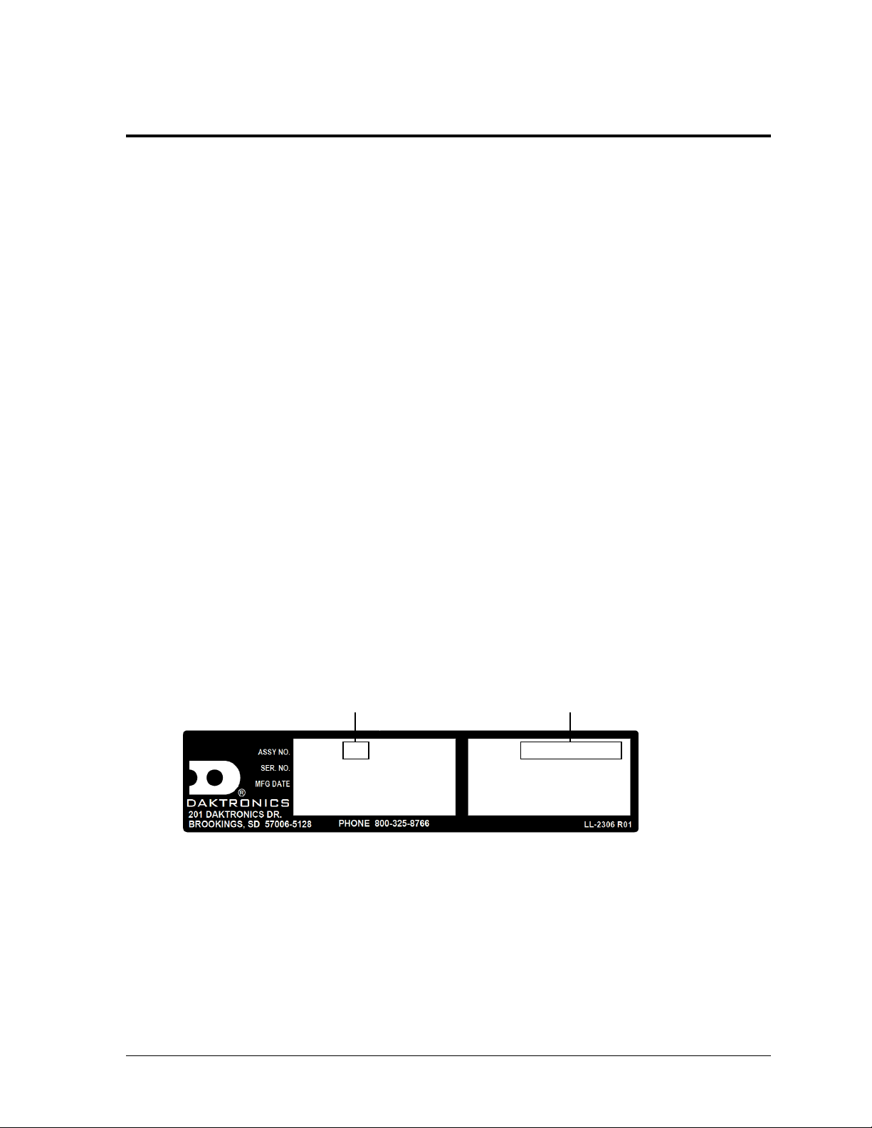
Figure 1: Specifications Label
0A-1647-0012 HRev: 00
SN: 1001
05/15/13
3219728 0001
BA-2025-201X
VOLTS: 120V AC
AMPS: 7.5
WATTS: 900
Product Number
Model Number
Section 1: Introduction
This manual explains the troubleshooting of Daktronics Outdoor LED Scoreboards. For additional
information regarding the safety, installation, operation, or service of this system, refer to the telephone
numbers listed in Section 4. This manual is not specific to a particular installation. Project-specific
information takes precedence over any other general information found in this manual.
IMPORTANT SAFEGUARDS:
Please read and understand all instructions before servicing the scoreboard.
Do not drop control equipment or allow it to get wet.
Do not disassemble control equipment or electronic controls of the display; failure to
follow this safeguard will make the warranty null and void.
Disconnect display power when not in use or when servicing.
Disconnect display power before servicing power supplies to avoid electrical shock.
Power supplies run on high voltage and may cause physical injury if touched while
powered.
Do not modify the scoreboard structure or attach any panels or coverings to the
scoreboard without the express written consent of Daktronics, Inc.
1.1 Specifications Label
Power specifications as well as serial and model number information can be found on an ID
label on the display, similar to the one shown in Figure 1.
Please have the assembly number, model number, and the date manufactured on hand when
calling Daktronics customer service to ensure the request is serviced as quickly as possible.
Knowing the facility name and/or job number will also be helpful. Note that the Product
Number(s) are sometimes used to distinguish different generations of the scoreboards having
the same model number.
Introduction 1
Main Component Labels
Part Type
Part Number
Individual circuit board
0P-XXXX-XXXX
Assembly; a collection of circuit boards
0A-XXXX-XXXX
Wire or cable
W-XXXX
Fuse
F-XXXX
Transformer
T-XXXX
Metal part
M-XXX
Fabricated metal assembly
0S-XXXXXX
Specially ordered part
PR-XXXXX-X
Accessory Labels
Component
Label
Termination block for power
or signal cable
TBXX
Grounding point
EXX
Power or signal jack
JXX
Power or signal plug for the
opposite jack
PXX
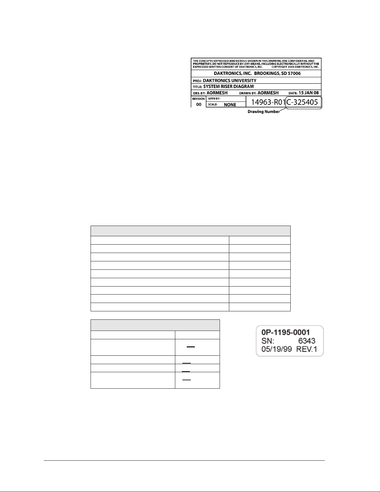
Figure 2: Daktronics Drawing Label
Figure 3: Typical Label
1.2 Resources
Figure 2 illustrates a Daktronics drawing
label. The drawing number is located in
the lower-right corner of a drawing. This
manual refers to drawings by listing the
last set of digits and the letter preceding
them. In the example, the drawing would
be referred to as Drawing C-325405.
Reference Drawing:
System Riser Diagram ............................................................................Drawing C-325405
Daktronics identifies manuals by the DD or ED number located on the cover page of each
manual. For example, this manual would be referred to as DD2124597.
1.3 Daktronics Nomenclature
Most components within this display carry a white label that lists the part number of the unit.
If a component is not found in the Replacement Parts List in Section 2.10, use the label to
order a replacement. Figure 3 illustrates a typical label. The part number is in bold.
Following the Replacement Parts List is the Daktronics Exchange Policy and the Repair &
Return Program. Refer to these instructions if replacing or repairing any display component.
1.4 Product Safety Approval
Daktronics outdoor scoreboards are ETL listed and tested to CSA standard for outdoor use.
Contact Daktronics with any questions regarding testing procedures.
2 Introduction
Problem
Possible Cause
Solution/Items to Check
Scoreboard doesn’t light
and console doesn’t work
No power to the scoreboard
Check that the main circuit breaker
for the scoreboard is on.
Check that the scoreboard is
receiving the correct 120 (or 240)
VAC power (see Appendix A).
No power to console
Ensure the console is plugged into a
120 (or 240) VAC power supply.
Swap the console with one known to
work correctly, and enter the proper
sport code and/or radio settings to
test. Replace console if necessary.
Scoreboard digits don’t light,
but console works
No wired signal from console
Check that the scoreboard is
receiving the correct 120 (or 240)
VAC power (see Appendix A).
Check that the red DS2 LED on the
driver lights up when sending
commands from the control console
(see Section 2.6).
No radio signal from console
Cycle power to the scoreboard and
watch for radio receiver broadcast/
channel settings (see Section 2.8).
Section 2: Scoreboard Troubleshooting
IMPORTANT NOTES:
1. Always disconnect power before doing any repair work on the scoreboard.
2. Permit only qualified service personnel to access internal display electronics.
3. Disconnect power when not using the scoreboard.
Note: For assistance in the maintenance of team name message centers (TNMCs), electronic captions,
or other optional scoreboard message centers, refer to Section 3 or the service manual that
accompanies those units.
2.1 Troubleshooting Table
The table below lists potential problems with the scoreboard and indicates possible causes
and corrective actions. This list does not include every symptom that may be encountered,
but it does present several of the most common situations that may occur.
Many of the solutions offered below provide references to other sections within this manual
or to supplemental product manuals with further detail on how to fix the problem.
If a problem occurs that is not listed or that cannot be resolved using the solutions in the
following table, contact Daktronics using the information provided in Section 4.
Scoreboard Troubleshooting 3
Problem
Possible Cause
Solution/Items to Check
Check that the green POWER and
amber RADIO IN RANGE indicators
on the radio receiver in the
scoreboard light up when the control
console is powered on (see Section
2.8). Keep the console between 20
to 1500 feet from the scoreboard.
Move the console 20-30 feet from
the scoreboard and test again.
Verify that both the console and
scoreboard antennae are securely
tightened and in a vertical position.
Replace the radio receiver.
No signal to driver
Check that the scoreboard is
receiving the correct 120 (or 240)
VAC power (see Appendix A).
Check that the red DS2 LED on the
driver lights up when sending
commands from the control console
(see Section 2.6).
Swap the driver with one known to
work correctly and with the same
part number to verify the problem.
Replace if necessary (see Section
2.6).
No power to driver
Check that the green DS1 LED on
the driver is always lit up when the
scoreboard is powered on
(see Section 2.6).
Scoreboard digits light, but
not in the correct order
Incorrect sport code
Ensure the correct sport code is
being used for the scoreboard
model. Refer to the operation
manual for the console being used.
Incorrect driver address
Check that the scoreboard driver(s)
are set to the correct address(es)
(see Section 2.6)
Scoreboard digits light,
console works, but no
display on scoreboard
No wired signal from console
(see solution on previous page)
No radio signal from console
(see solution on previous page)
Bad/damaged field wiring
Check that the red DS2 LED on the
driver lights up when sending
commands from the control console
(see Section 2.6)
Scoreboard works, but some
LEDs always stay on
Short in digit, segment, or
indicator circuit
Swap the digit/segment/indicator
with one known to work correctly to
verify the problem. Replace if
necessary (see Sections 2.3-2.5).
4 Scoreboard Troubleshooting
Problem
Possible Cause
Solution/Items to Check
Scoreboard works, but some
LEDs do not light or they
blink
Bad connection
Verify the connector on the back of
the digit circuit board is secure
(see Sections 2.3-2.5).
Bad digit or driver
Swap the digit/driver with one known
to work correctly to verify the
problem. Replace if necessary
(see Sections 2.3-2.5 for digits or
Section 2.6 for drivers).
Scoreboard works, but some
digits do not light
Bad digit or driver
(see solution above)
Incorrect sport code
(see solution on previous page)
Incorrect driver address
(see solution on previous page)
Wrong console controlling
scoreboard
Another console’s radio signal could
be transmitting to the scoreboard.
An example would be football and
baseball scoreboards that are within
1500 feet of each other
(see Section 2.8).
Radio interference
There may be other radio
transmissions in the area that
overpower the console. If it is not
possible to disable the interfering
device, It may be necessary to run a
wired signal connection instead.
Bad breakout board on
segmented digit
(white digits only)
Replace the breakout board with
one known to work correctly to verify
the problem. Replace if necessary
(see Section 2.4).
Blown fuse(s) on power supply
circuit board (white digits only)
Replace the fuse(s) on the circuit
board (see Section 2.7).
Scoreboard works, but a
certain section of digits do
not light
Bad multi-section connection
Verify power/signal interconnect(s)
between scoreboard sections
properly connected. Refer to
appropriate scoreboard installation
manual and/or schematic drawings.
Bad power supply
Swap the power supply with one
known to work correctly to verify the
problem. Replace if necessary
(see Section 2.7).
Bad power supply circuit board
(white digits only)
Swap the circuit board with one
known to work correctly to verify the
problem. Replace if necessary
(see Section 2.7).
Speed of Pitch (SOP) digits
do not light
No signal to SOP driver
Ensure there is a separate signal
run connected to the SOP driver
from a dedicated All Sport console
using code 5500. Refer to schematic
drawings and ED-12224.
Scoreboard Troubleshooting 5
Figure 4: Component Location Labeling
Figure 5: LED Digit Panel
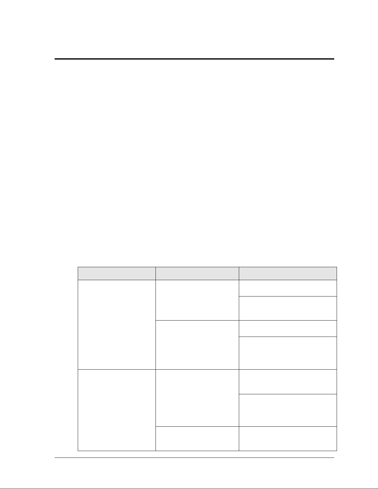
2.2 Component Locations & Access
Component location varies with
each scoreboard model. Refer to
the component location drawings
attached to the product
specification sheets listed in
Appendix A. For component
locations of scoreboards with white
digits and Modular Football
Scoreboards, refer to the tables in
Appendix A.
All internal electronic components
are reached by opening a digit
panel or an access door.
Look for labels similar to those shown in Figure 4 to access primary scoreboard components.
Note that the same labels are on both front and rear access panels.
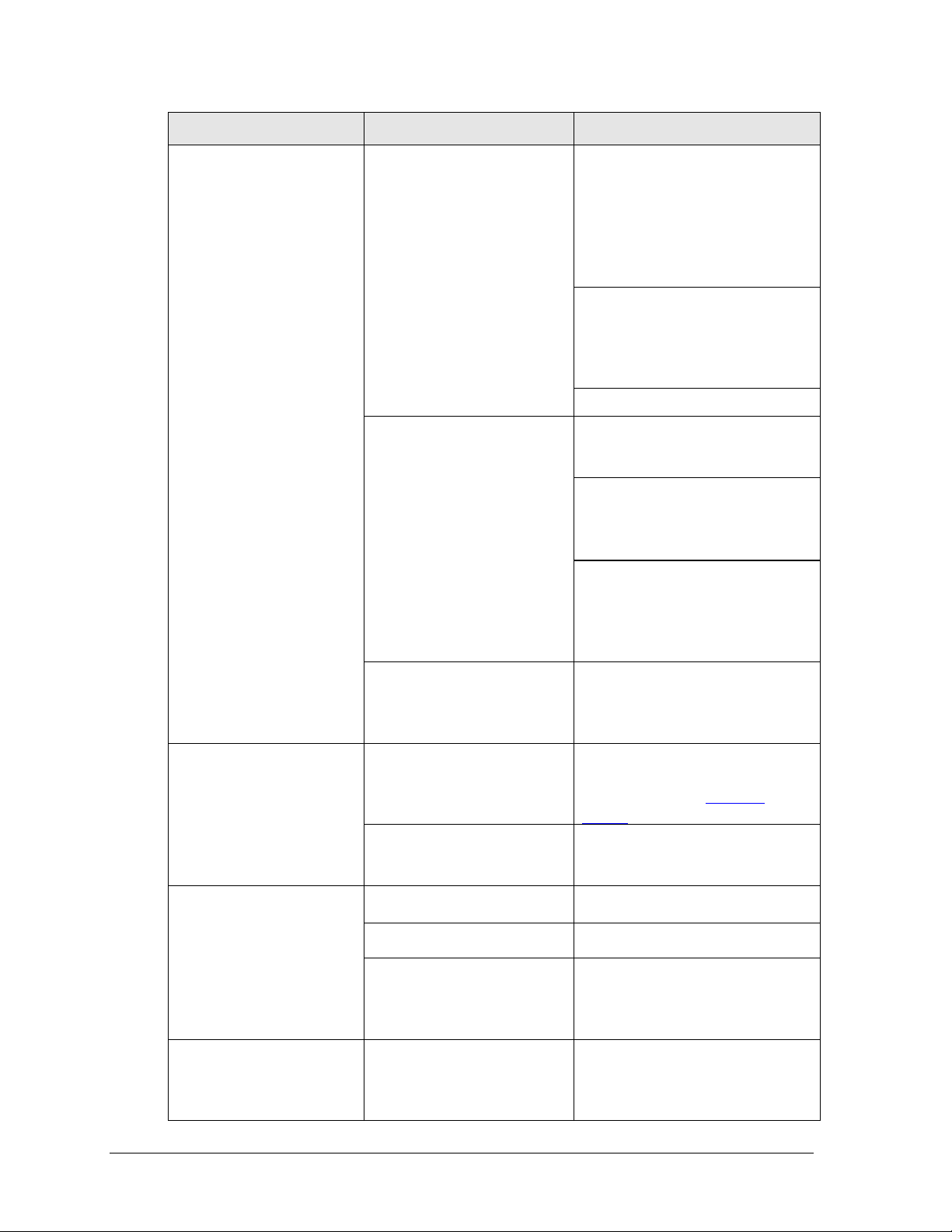
Digit panels are held in place on the
scoreboard face by an offset flange
across the top and by screws at the
bottom, as shown in Figure 5.
To open a digit panel:
1. Hold the digit panel in
place by putting hand
pressure on it and remove
the holding screws.
2. Carefully lift the panel
away from the scoreboard,
sliding it out and down.
Note: If the panel is not
held in place when the
screws are removed, it
could drop and possibly
damage LEDs or the digit
harness.
With a non-digit access panel, simply remove the top, side and bottom screws holding it in
place. Some panels are hinged and swing open when the screws are removed or loosened.
Rear access panels can be lifted up and out over the screws through keyholes.
Note: When closing a digit or access panel, make sure all screws/latches are holding it
firmly in place to prevent moisture and debris from entering the scoreboard.
6 Scoreboard Troubleshooting
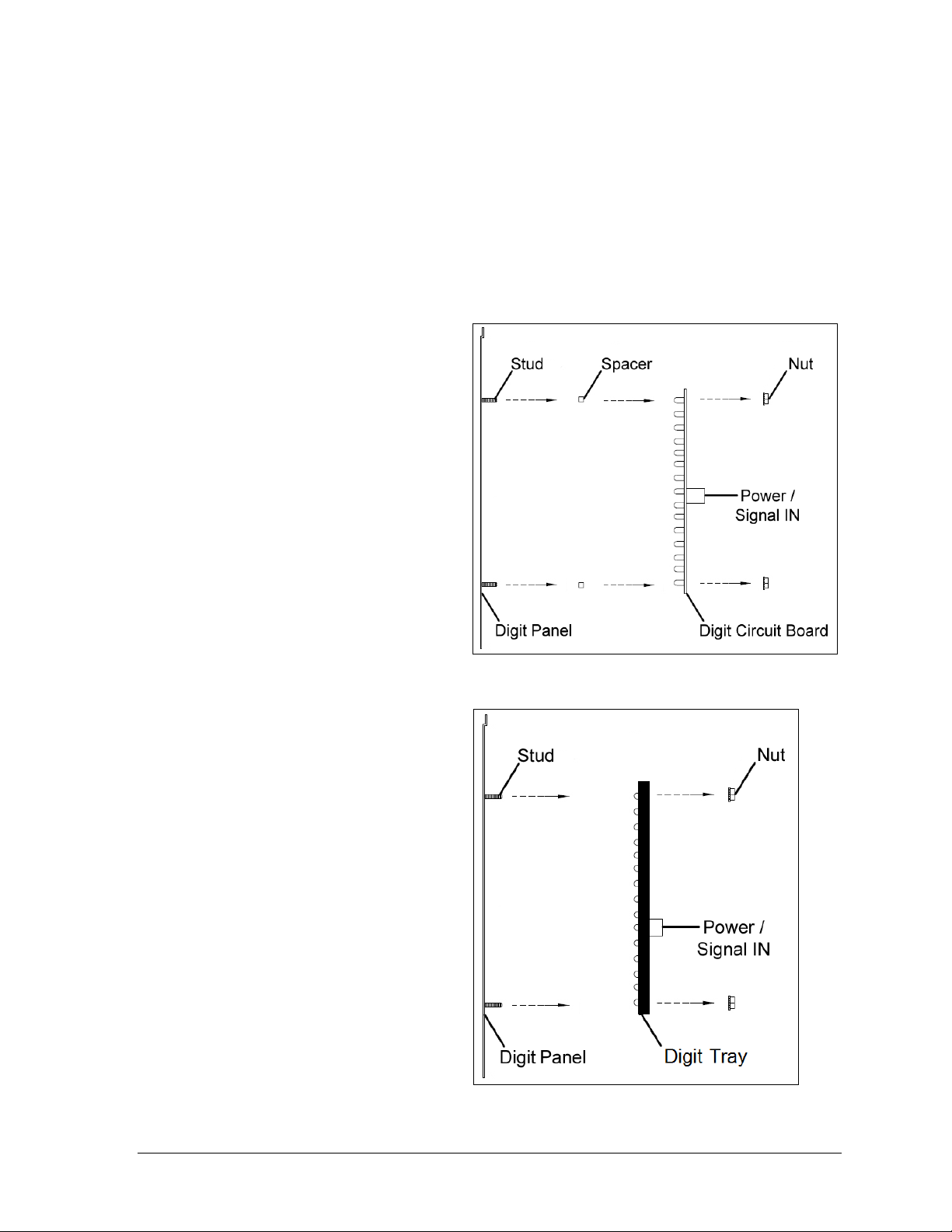
Figure 6: Digit Panel Assembly
Figure 7: Weather-Sealed Digit Panel Assembly
2.3 Replacing Digits
Digits that are 18" or smaller have LEDs embedded on a single circuit board that is mounted
to the back of a digit panel, as shown in Figure 6. Newer weather-sealed digits consist of a
digit circuit board mounted to a black polycarbonate tray and encased in protective gel as
shown in Figure 7. Multiple digits may also be secured to a single face panel. Do not attempt
to remove individual LEDs; in the case of a malfunctioning LED or digit segment, replace the
entire digit circuit board.
To replace a digit circuit board:
1. Open the digit panel as
described in Section 2.2.
2. Disconnect the power/signal
plug from the back of the
digit by squeezing together
the locking tabs and pulling
the connector free.
3. Use a
4. Position a new digit over the
5. Tighten the nuts.
6. Reconnect the power/signal
7. Close and secure the digit
9
/32" nut driver to
remove the nuts securing the
digits to the inside of the
panel, and then lift the digit
off the standoff studs.
studs, making sure the rubber
side of the rubber-backed
spacer is facing the digit
circuit board. Weather-sealed
digits do not require spacers.
connector.
Note: This is a keyed
connector and it will attach in
one way only. Do not attempt
to force the connection.
panel, then power up and test
the scoreboard to see if
changing the digit has
resolved the problem.
Scoreboard Troubleshooting 7
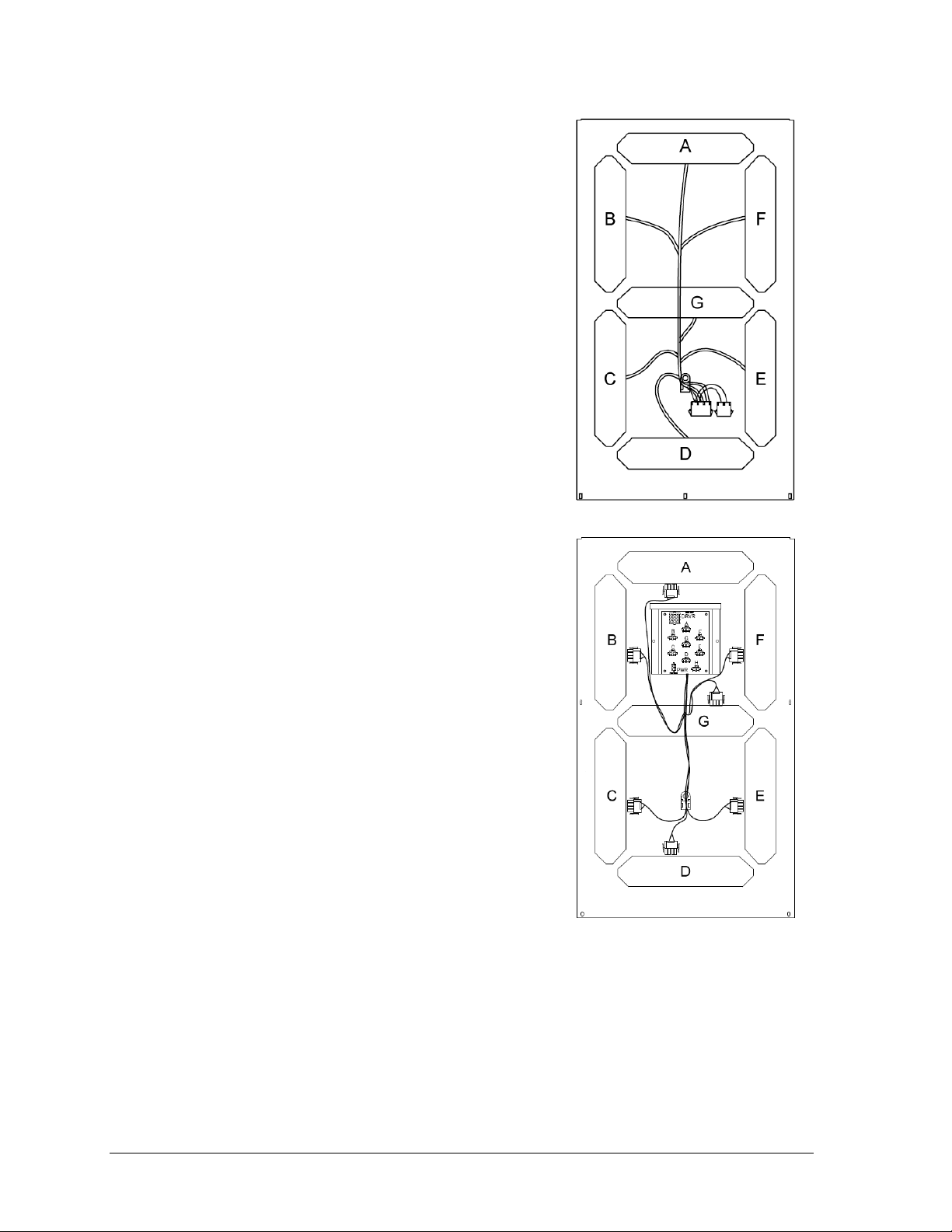
Figure 8: Digit Segments & Panel
Figure 9: Breakout Board Enclosure
(Cover Removed)
2.4 Replacing Digit Segments
Digits that are 24" or larger are composed of seven
circuit board segments. As with smaller digits, the digit
segment circuit boards are mounted to the back of the
digit panel (Figure 8). Do not attempt to remove
individual LEDs; it may be possible to make repairs by
removing just the defective segment.
To replace a digit segment:
1. Open the digit panel as described in Section 2.2.
2. Disconnect the 2- or 4-pin power/signal
connectors from the back of the digit segment by
squeezing together the locking tabs and pulling
the connector free.
3. Use a
4. Position a new digit segment over the studs,
5. Tighten the nuts.
6. Reconnect the power/signal connector.
7. Close and secure the digit panel, then power up
Some LED digit segments are connected to a
breakout board (Figure 9). If all the segments of an
entire digit do not work, it may be necessary to
replace the breakout board instead. Breakout boards
are replaced in the same manner as a digit segment.
9
/32" nut driver to remove the nuts
securing the digit segment to the inside of the
panel, and then lift the digit segment off the
standoff studs.
making sure the rubber side of the rubberbacked spacer is facing the digit circuit board.
Weather-sealed digit segments do not require
these spacers.
Note: This is a keyed connector and it will attach
in one way only. Do not attempt to force the
connection.
and test the scoreboard to see if changing the
digit segment has resolved the problem.
2.5 Replacing Colons, Decimals & Indicators
Colons, decimals, and other indicators are replaced in the same manner as a digit segment.
Some indicators will be connected to a breakout board (Figure 9). If no indicators work,
it may be necessary to replace the breakout board instead. Breakout boards are replaced in
the same manner as a digit segment.
8 Scoreboard Troubleshooting
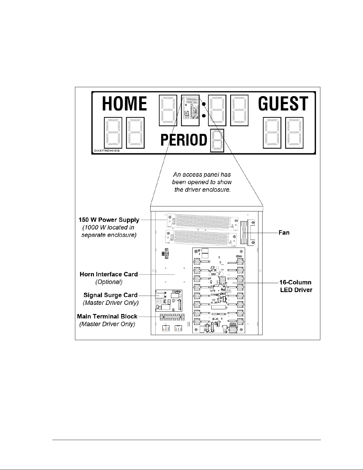
Figure 10: Driver Enclosure Components (Cover Removed)
2.6 LED Drivers
The LED drivers perform the task of switching digits on and off within the scoreboard.
LED drivers are located inside of a driver enclosure. Refer to Figure 10 to view the location
and components of a driver enclosure.
Most scoreboard models use 16-column drivers (Figure 11), while smaller models use 8column drivers. Several scoreboard models also contain more than one driver to accommodate
all of the digits and indicators. Refer to the component location drawings in Appendix A to
determine the type and number of drivers for a particular scoreboard model. Also refer to
Appendix B to locate the appropriate schematic drawings.
Scoreboard Troubleshooting 9
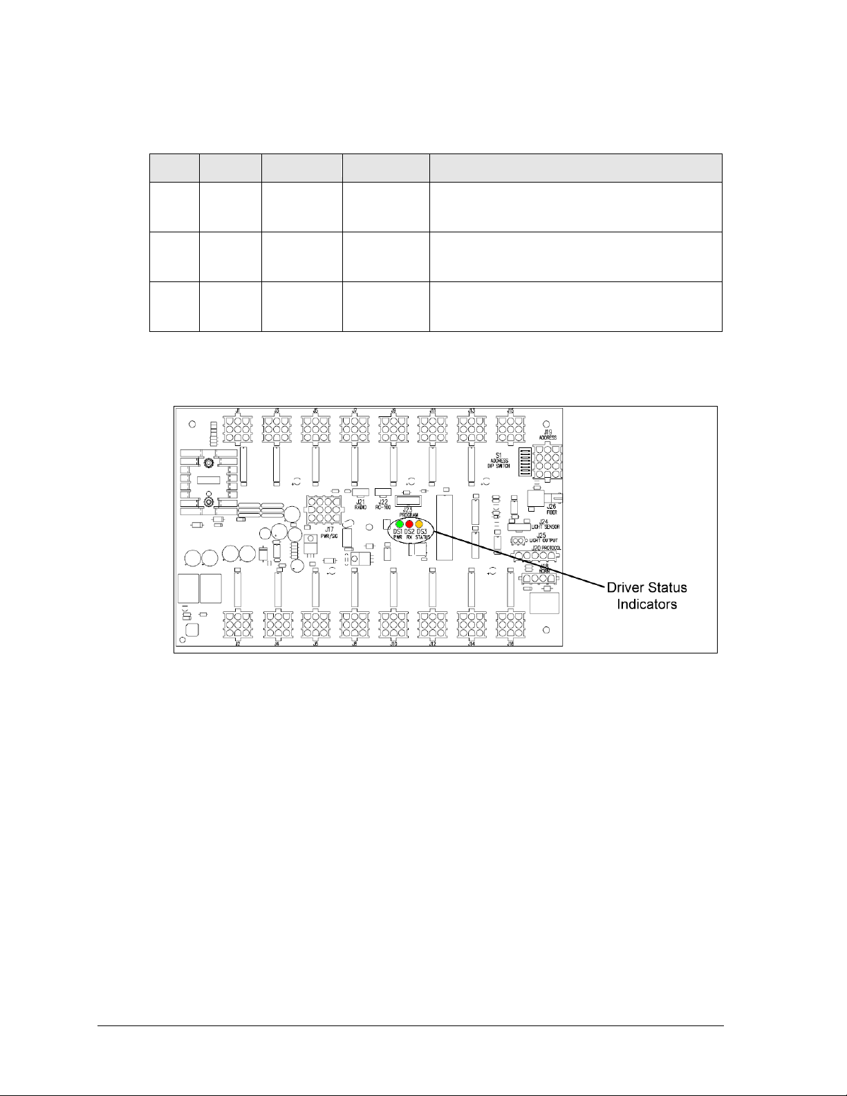
LED
Color
Function
Operation
Summary
DS1
Green
Power
Steady on
DS1 will be on and steady to indicate the driver
has power.
DS2
Red
Signal RX
Steady on
or blinking
DS2 will be on or blinking when the driver is
receiving a signal and off when there is no signal.
DS3
Amber
Status
Blinking
DS3 will be blinking at one second intervals to
indicate the driver is running.
Figure 11: Driver Status Indicators (16-Column)
When troubleshooting driver problems, three LEDs labeled DS1, DS2, and DS3 in Figure 11,
provide the following diagnostic information:
Note: While it is necessary to have the scoreboard powered on to check the LED
indicators, always disconnect scoreboard power before servicing.
Replacing a Driver
1. Open the digit panel or scoreboard face panel as described in Section 2.2.
2. Loosen the screws securing the metal cover to the driver enclosure, and then lift it up
and off the keyholes.
3. Disconnect all connectors from the driver by squeezing together the locking tabs and
pulling the connectors free. It may be helpful to label the cables to know which cable
goes to which connector when reattaching the driver.
4. Remove the screws or nuts securing the driver to the inside of the enclosure.
5. Carefully lift the driver from the display and place it on a clean, flat surface.
6. Position a new driver over the screws and tighten the nuts.
7. Reconnect all power/signal connectors.
Note: The connectors are keyed and will attach in one way only. Do not attempt to
force the connections.
8. Ensure the driver is set to the correct address (refer to Setting the Driver Address).
9. Close and secure the digit panel, then power up and test the scoreboard to see if
changing the driver has resolved the problem.
10 Scoreboard Troubleshooting
 Loading...