

Daktronics Outdoor LED Scoreboards User Manual
Multi-Section Models
BA-1518
FB-2020
MS-2009
BA-2025
FB-2021
MS-2918
BA-2026
FB-2022
SO-2011
BA-2027
FB-2023
SO-2018
BA-2028
FB-2024
SO-2019
BA-2029
FB-2025
SO-2021
BA-2125
FB-2026
SO-2023
BA-2127
FB-2027
SO-2043
FB-2018
FB-2028
FB-2019
FB-3010
Outdoor LED Scoreboards
Installation Manual
DD2956757 Rev 0 – 22 April 2015
Single-Section Models
BA-618
BA-2718
RO-2010
BA-624
CR-2002
RO-2011
BA-2005
CR-2003
SO-918
BA-2010
FB-824
SO-2008
BA-2014
FB-4005
SO-2013
BA-2017
FB-2030
SO-2918
BA-2019
MS-915
TI-218
BA-2022
MS-918
TI-2003
BA-2023
MS-2002
TI-2010
BA-2030
MS-2004
TI-2012
BA-2031
MS-2006
TI-2015
BA-2515
MS-2012
TI-2019
BA-2518
MS-2024
TI-2024
BA-2618
MS-2025
TI-2032
BA-2715
MS-3918
TI-2033
Modular Football Scoreboards
FB-2500 Series
FB-2600 Series
Tennis Models
TN-2603
TN-2652
TN-2604
TN-2653
TN-2605
TN-2654
TN-2606
TN-2655
TN-2607
TN-2656
TN-2650
TN-2657
TN-2651
Pari-Mutuel Models
PM-2100
PM-2108
PM-2101
PM-2109
PM-2102
PM-2110
PM-2103
PM-2111
PM-2104
PM-2112
PM-2105
PM-2113
PM-2106
PM-2114
PM-2107
201 Daktronics Drive PO Box 5128 Brookings, SD 57006-5128
Tel: 1-800-DAKTRONICS (1-800-325-8766) Fax: 605-697-4746
www.daktronics.com/support


DD2956757
Product 1164, 1198, 1647, & 1753
Rev 0 – 22 April 2015
DAKTRONICS, INC.
Copyright 2015
All rights reserved. While every precaution has been taken in the preparation of this manual, the publisher
assumes no responsibility for errors or omissions. No part of this book covered by the copyrights hereon may be
reproduced or copied in any form or by any means – graphic, electronic, or mechanical, including photocopying,
taping, or information storage and retrieval systems – without written permission of the publisher.
All Sport® and PanaView® are trademarks of Daktronics, Inc. Other trademarks used in this manual are the property of their
respective owners.


Table of Contents
Section 1: Introduction ............................................................................................................................ 1
1.1 Specifications Label................................................................................................................. 1
1.2 Scoreboard Controllers ........................................................................................................... 2
Sport Codes ....................................................................................................................... 2
1.3 Troubleshooting ...................................................................................................................... 2
1.4 Product Safety Approval........................................................................................................ 2
Section 2: Mechanical Installation ........................................................................................................ 3
2.1 Lifting the Scoreboard ............................................................................................................ 3
2.2 Extrusion Scoreboard Mounting ........................................................................................... 4
I-Beam Clamps ................................................................................................................. 5
Clamping Angles ............................................................................................................. 6
Mounting Tubes ............................................................................................................... 6
2.3 Sheet Metal Scoreboard Mounting ....................................................................................... 7
Clamping Angles ............................................................................................................. 7
I-Beam Clamps ................................................................................................................. 8
2.4 Ad Panel Mounting................................................................................................................. 9
Unistrut Attachment ........................................................................................................ 9
I-Beam Clamps ............................................................................................................... 10
2.5 Scoreboard Protective Devices ............................................................................................ 11
Section 3: Electrical Installation .......................................................................................................... 13
3.1 Installation Overview ........................................................................................................... 13
3.2 Power ...................................................................................................................................... 14
Grounding ....................................................................................................................... 15
Lightning Protection ...................................................................................................... 15
Connection ...................................................................................................................... 16
Multi-Court Tennis Power Connection ....................................................................... 17
3.3 Power-On Self-Test (POST) ................................................................................................. 18
3.4 Wired Signal Connection ..................................................................................................... 18
Copper Signal ................................................................................................................. 18
Fiber Optic Signal ........................................................................................................... 19
Multiple Driver Connections ........................................................................................ 19
3.5 Wireless Signal Connection ................................................................................................. 19
All Sport Control ............................................................................................................ 19
RC-100 Control ............................................................................................................... 19
Radio Settings ................................................................................................................. 20
3.6 Power/Signal Connections Between Sections ................................................................... 20
Two-Section Models ...................................................................................................... 20
Four-Section Models ...................................................................................................... 21
Modular Football Scoreboards ..................................................................................... 23
Three-Section Tennis Models ....................................................................................... 25
Four-Section Tennis Models ......................................................................................... 26
Pari-mutuel Displays ..................................................................................................... 26
Section 4: Daktronics Exchange and Repair & Return Programs .................................................. 27
4.1 Exchange Program ................................................................................................................ 27
Before Contacting Daktronics....................................................................................... 27
Table of Contents i

4.2 Repair & Return Program .................................................................................................... 28
Shipping Address ........................................................................................................... 28
4.3 Daktronics Warranty and Limitation of Liability ............................................................. 28
Section 5: Scoreboard Options ............................................................................................................. 29
5.1 Time of Day Mode ................................................................................................................ 29
5.2 Team Name Message Centers (TNMCs) ............................................................................ 30
5.3 Trumpet Horns ...................................................................................................................... 30
5.4 Time Outs Left (T.O.L) Digits .............................................................................................. 30
5.5 Changeable Caption Kits ...................................................................................................... 30
5.6 Portable Power Pack Hookup Option ................................................................................ 31
Appendix A: Specifications ........................................................................................................................ 33
Appendix B: Reference Drawings ............................................................................................................ 37
Appendix C: Daktronics Warranty and Limitation of Liability .......................................................... 39
ii Table of Contents
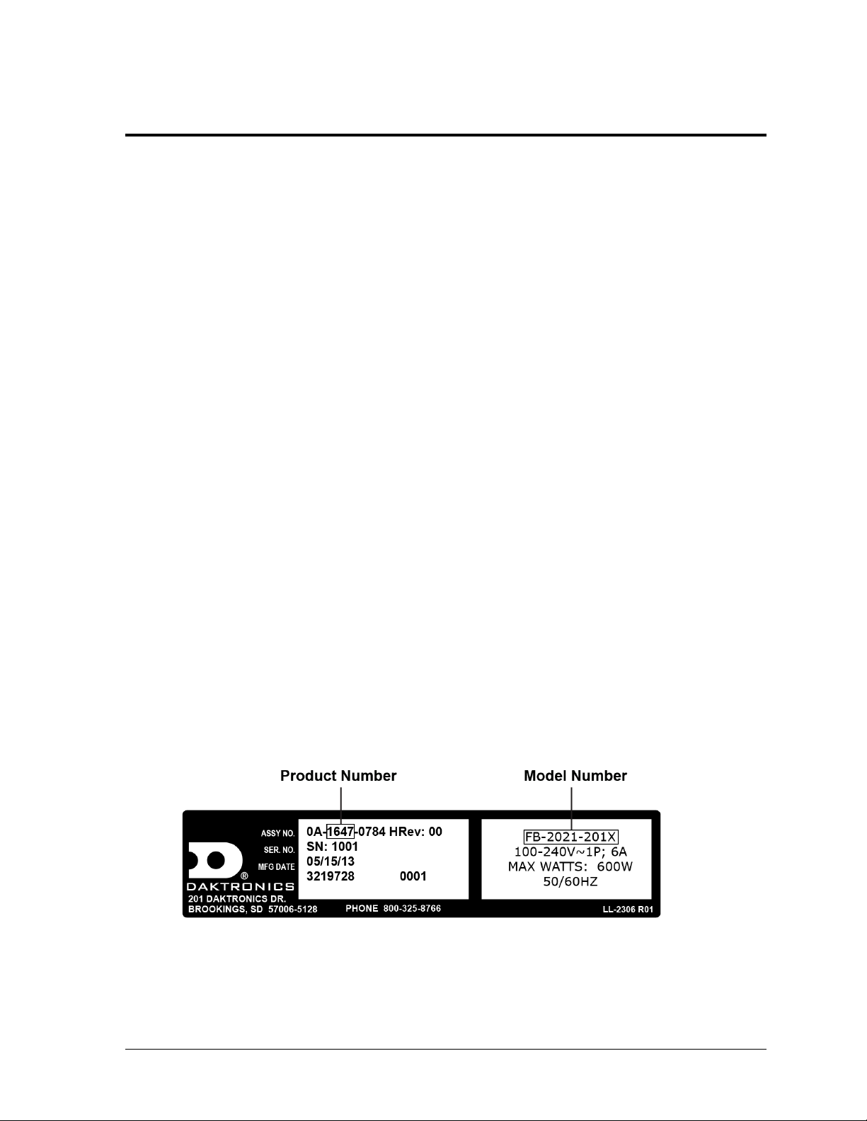
Figure 1: Specifications Label
Section 1: Introduction
This manual explains the installation of Daktronics Outdoor LED Scoreboards. For additional
information regarding the safety, installation, operation, or service of these displays, refer to the
Daktronics Customer Service contact information in Section 4. This manual is not specific to a
particular installation.
IMPORTANT SAFEGUARDS
Read and understand all instructions before beginning the installation process.
Properly ground the cabinet with a grounding electrode at the scoreboard location.
Disconnect display power when not in use or when servicing.
Disconnect display power before servicing power supplies to avoid electrical shock.
Power supplies run on high voltage and may cause physical injury if touched
while powered.
Do not modify the structure or attach any panels or coverings to the scoreboard
without the express written consent of Daktronics.
Do not disassemble control equipment or electronic controls of the scoreboard;
failure to follow this safeguard will make the warranty null and void.
Do not drop control equipment or allow it to get wet.
Project-specific information takes precedence over any other general information found in
this manual. Such information may include:
Shop Drawings: describe mounting methods to structural elements, access method
(front or rear), and power and signal entrance points
System Risers: describe power and signal connections between display components
and the control location; may also include control room layout and schematic
Ensure all applicable material has been gathered before beginning the installation. Contact a
Daktronics sales coordinator or project manager.
1.1 Specifications Label
Introduction 1
Power specifications as well as serial and model number information can be found on an ID
label on the display, similar to the one shown in Figure 1.
Please have the assembly number, model number, and the date manufactured on hand when
calling Daktronics customer service to ensure the request is serviced as quickly as possible.
Knowing the facility name and/or job number will also be helpful. Note that the Product
Number(s) are sometimes used to distinguish different generations of the scoreboards having
the same model number.
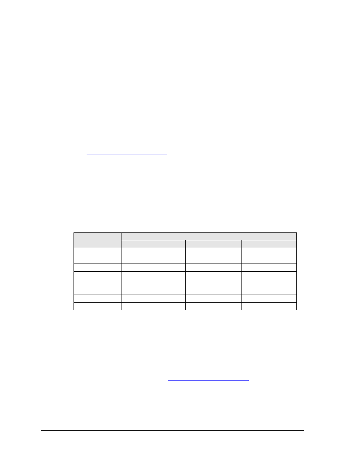
Sport
Common Code(s)
All Sport 5000
All Sport 1600
RC-100
Baseball
5501
03 (w/ clock = 23)
03 (w/ clock = 23)
Pitch & Speed
5500
N/A
N/A
Football
6601
01
61
Lacrosse/
Field Hockey
4601
01
01
Soccer
7701
01
01
Tennis
220
08
08
Track
8601 (manual timing)
N/A
N/A
1.2 Scoreboard Controllers
Daktronics outdoor scoreboards are designed for use with the All Sport® 5000 series control
consoles. Some smaller models may also be controlled with the All Sport 1600 or the RC-100
handheld controller. The consoles use keyboard overlays (sport inserts) to control numerous
sports and scoreboard models. Refer to the following manuals for operating instructions:
All Sport 1600 Series Control Console Operation Manual (ED-12462)
All Sport 5000 Series Control Console Operation Manual (ED-11976)
Remote Control System RC-100 All Sport Operation Manual (ED-15133)
DakTennis Version 3 Installation & Operation Manual (DD1965926) –
This software is required for multi-court tennis scoreboards with optional TNMCs.
These manuals are provided on a CD with the control consoles, and they are also available
online at www.daktronics.com/manuals.
Daktronics pari-mutuel displays are designed to be controlled by third-party tote software.
Software providers must have permission to output data in a specific format for Daktronics
displays. Contact Daktronics for approved providers. Refer to the documentation from the
particular software provider for operating instructions.
Sport Codes
Below is a table of common sport codes. Note that many scoreboards are capable of scoring
multiple sports. Refer to the controller operation manual for a complete listing of sport codes.
1.3 Troubleshooting
For an extensive troubleshooting guide and instructions on how to replace scoreboard
components, refer to the following manual:
Outdoor LED Scoreboards Service Manual (DD3000541)
The service manual is available online at www.daktronics.com/manuals.
1.4 Product Safety Approval
2 Introduction
Daktronics outdoor scoreboards are ETL-listed, tested to CSA standards, and CE labeled.
Contact Daktronics with any questions regarding testing procedures.
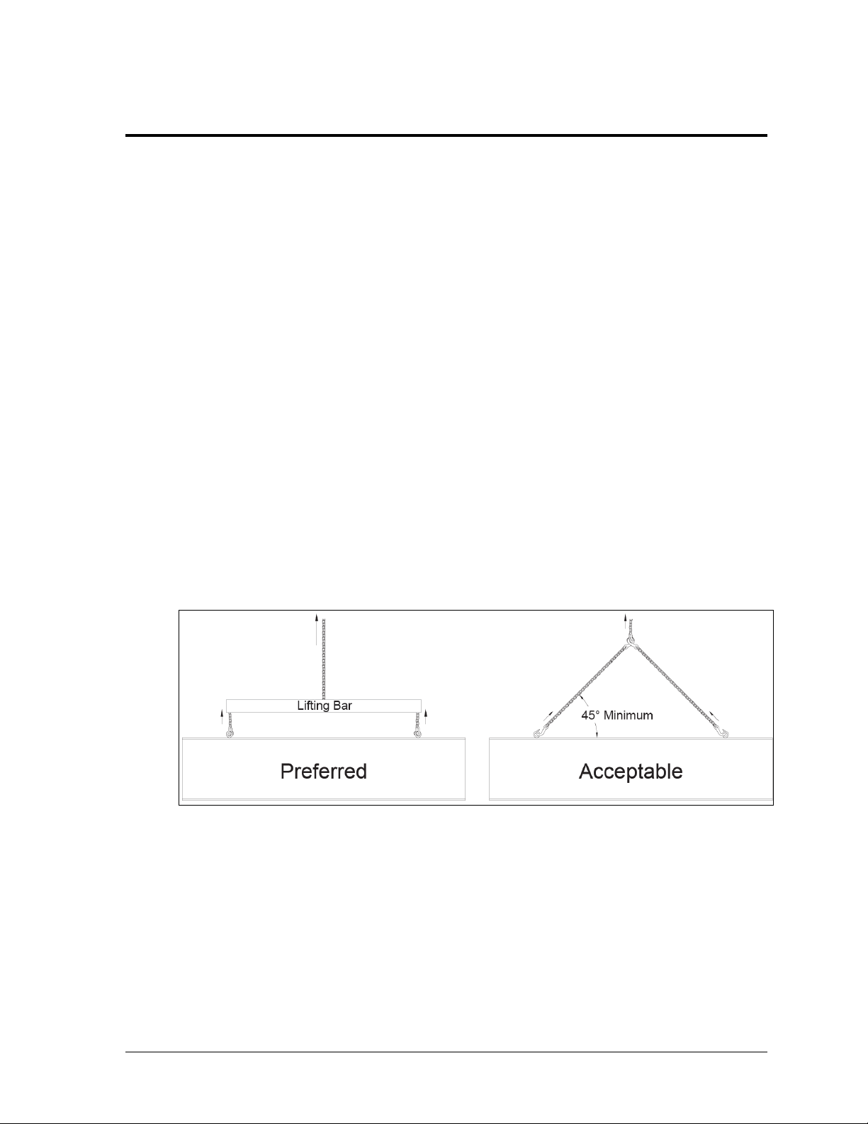
Figure 2: Lifting Methods
Section 2: Mechanical Installation
Mechanical installation consists of installing concrete footing and steel beams and mounting the
scoreboard and accompanying ad panels to the beams. The product specification sheets listed in
Appendix A include installation specification drawings that show the recommended number of
beams and spacing between them. The drawings also indicate the size of beams required to support
the scoreboard at different heights and at various wind speeds. For Modular Football scoreboards
and Pari-Mutuel displays, refer to site-specific diagrams for proper placement and mounting method.
Any column and footing size dimensions are to assist with estimating installation costs; they are
estimates only and are not intended for actual construction purposes. Be sure that the installation
complies with local building codes and is suitable for the particular soil and wind conditions.
The columns, footings, and all connection details must be designed and certified by a professional
engineer licensed to practice in the state of the scoreboard installation.
Note: Daktronics does not assume any liability for any installation derived from the information
provided in this manual or installations designed and installed by others.
2.1 Lifting the Scoreboard
Scoreboards and scoreboard sections are shipped equipped with 1/2" shoulder-type eyebolts
located along the top of the cabinet for the purpose of lifting.
Daktronics strongly recommends using a spreader bar, or lifting bar, to lift the display.
Spreader bars ensure the force on the eyebolts remains straight up, minimizing lifting stress.
Figure 2 illustrates the preferred scoreboard lifting method on the left and an acceptable
alternative lifting method on the right. When lifting the display:
Use a spreader bar if possible.
Use every lifting point provided.
Cables and chains attached to the eyebolts and directly to a center lifting point, as shown in
the right-hand example in Figure 2, create a dangerous lateral force on the eyebolts and may
cause the eyebolts to fail. The smaller the angle between the cable and the top of the display,
the lighter the display must be to safely lift it. If this method must be used, ensure a minimum
angle between the chain and scoreboard of at least 45°.
Mechanical Installation 3
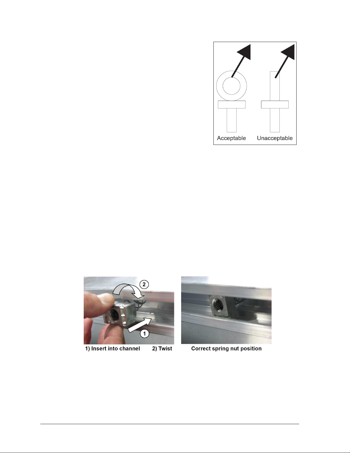
Figure 3: Eyebolt Plane Load
Figure 4: Spring Nut Insertion
Do NOT attempt to lift the display if the angle is less than
45°. Exceeding load angles or weight limits could cause
the bolts in the scoreboard cabinet to buckle, resulting in
serious damage to the scoreboard or injury to personnel.
Also, loads should be applied directly in the plane of the
eyebolt as shown in Figure 3.
Note: Daktronics assumes no liability for damages
resulting from incorrect setup or lifting methods.
Eyebolts are intended for lifting only. Do not attempt
to permanently support the display by the eyebolts.
In typical multi-section installations, the lower scoreboard
is installed first and secured to the support beams.
The upper section is then placed atop or above the lower
section and attached to the beams. Refer to Section 3.6 for
more information on the power/signal connections between sections.
If installers remove the eyebolts, plug the holes with bolts and the rubber washers that are
used with the eyebolts. Apply silicone or another waterproof sealant to the eyebolt openings.
Also inspect the top and sides of the display for any other holes or openings that may allow
moisture to enter the display, and plug and seal those openings.
2.2 Extrusion Scoreboard Mounting
Three standard mounting methods are available for scoreboards with extruded cabinets.
Each method requires spring nuts to be inserted into the rear channel of the scoreboard:
Once the spring nuts are in place, refer to the appropriate section below for the type of
mounting hardware provided with the scoreboard.
4 Mechanical Installation
1. Insert spring nuts into the top and bottom scoreboard channels. Twist the spring nuts
until they are perpendicular to the scoreboard channel (Figure 4).
Note: Each scoreboard section requires four spring nuts per beam (two at the top and
two at the bottom).
2. Measure the beam spacing and position a spring nut on either side of the beams.
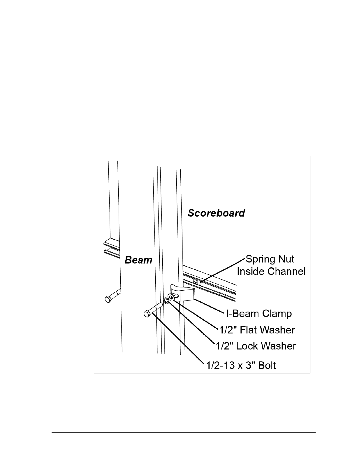
Figure 5: I-beam Clamp Mounting Method, Rear Isometric View
I-Beam Clamps
This mounting method is used to mount a scoreboard to I-beams with a flange thickness of
1
/4" – 3/4". If flange is thicker than 3/4", longer bolts will be required at added expense.
Mounting hardware includes I-beam clamps, 1/2-13 x 3" bolts, 1/2" flat washers, and 1/2" lock
washers. Refer to Figure 5 and Drawing A-1052565 in Appendix B.
1. Position a scoreboard section at the front of the beams, and lift it to the desired height.
2. Slide a lock washer, flat washer, and I-beam clamp onto the bolt, and loosely screw
the bolt into the spring nut.
3. Position each I-beam clamp assembly as close to the I-beam flanges as possible.
4. Make final adjustments in the positioning of the scoreboard section to ensure it is
flush and level, and firmly tighten all of the bolts.
5. Repeat steps 1-4 with all scoreboard sections.
Note: For four-section scoreboards mounting to three beams, mounting straps are
required along the middle beam to join the horizontal scoreboard sections together.
Refer to Drawing A-1115341 in Appendix B for more information.
Mechanical Installation 5
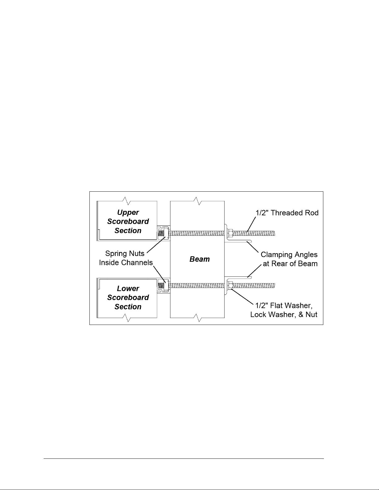
Figure 6: Clamping Angle Mounting Method, Side View
Clamping Angles
This mounting method may be used to mount a scoreboard to I-beams or any beam/pole that
does not have flanges.
Mounting hardware includes rear clamping angles; 1/2-13 x 24" threaded rods; and 1/2" nuts,
flat washers, and lock washers. Refer to Figure 6 and Drawing A-1048184 in Appendix B.
Note: The threaded rods do not pass through the beams; they run along both sides.
1. Screw a threaded rod into each of the spring nuts as far as it will go.
2. Position a scoreboard section at the front of the beams with the threaded rods
extending from the rear of the spring nuts, straddling the beams.
3. Lift the scoreboard section to the desired height.
4. Slide clamping angles over the ends of the rods and loosely install the washers and nuts.
5. Make final adjustments in the positioning of the scoreboard section to ensure it is
flush and level, and firmly tighten all of the 1/2" hex nuts.
6. Repeat steps 1-5 for all scoreboard sections.
Mounting Tubes
This mounting method may be used to mount a scoreboard to horizontal beams. The
mounting tubes are attached to the scoreboard using spring nuts and 1/2" hardware as
described above; this may be done during manufacturing or on site. Refer to Figure 7 and
Drawing A-1048268 in Appendix B for mounting tube assembly. The clip angles can be
adjusted vertically before they are bolted or welded to the horizontal beams. When using this
method, recommended attachment method and positioning of display pieces will be
provided in site-specific diagrams.
6 Mechanical Installation
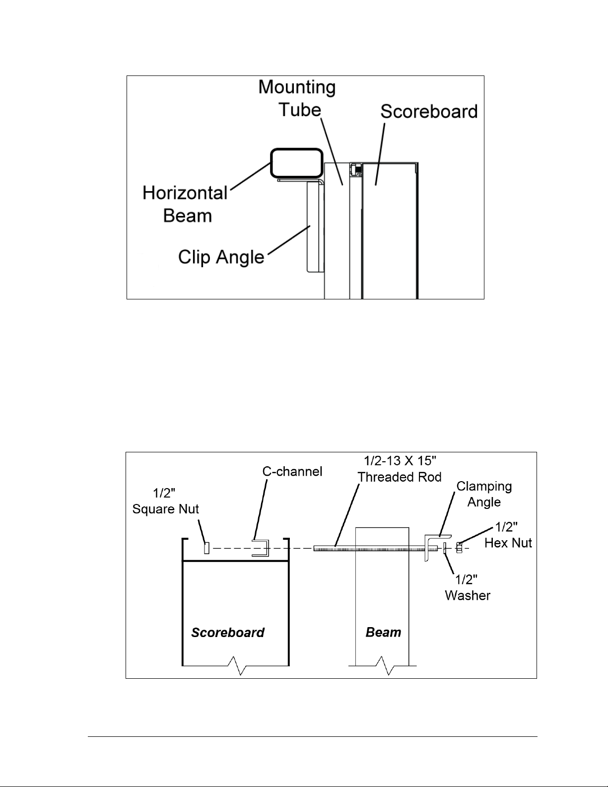
Figure 7: Mounting Tube Attachment, Side View
Figure 8: C-channel Mounting Method, Side View
2.3 Sheet Metal Scoreboard Mounting
Two standard mounting methods are available for scoreboards with sheet metal cabinets.
Clamping Angles
Mounting hardware includes C-channels; rear clamping angles; 1/2-13 x 15" threaded rods;
and 1/2" square nuts, hex nuts, and lock washers. Refer to Figure 8 and Drawing A-1130246
in Appendix B.
Mechanical Installation 7
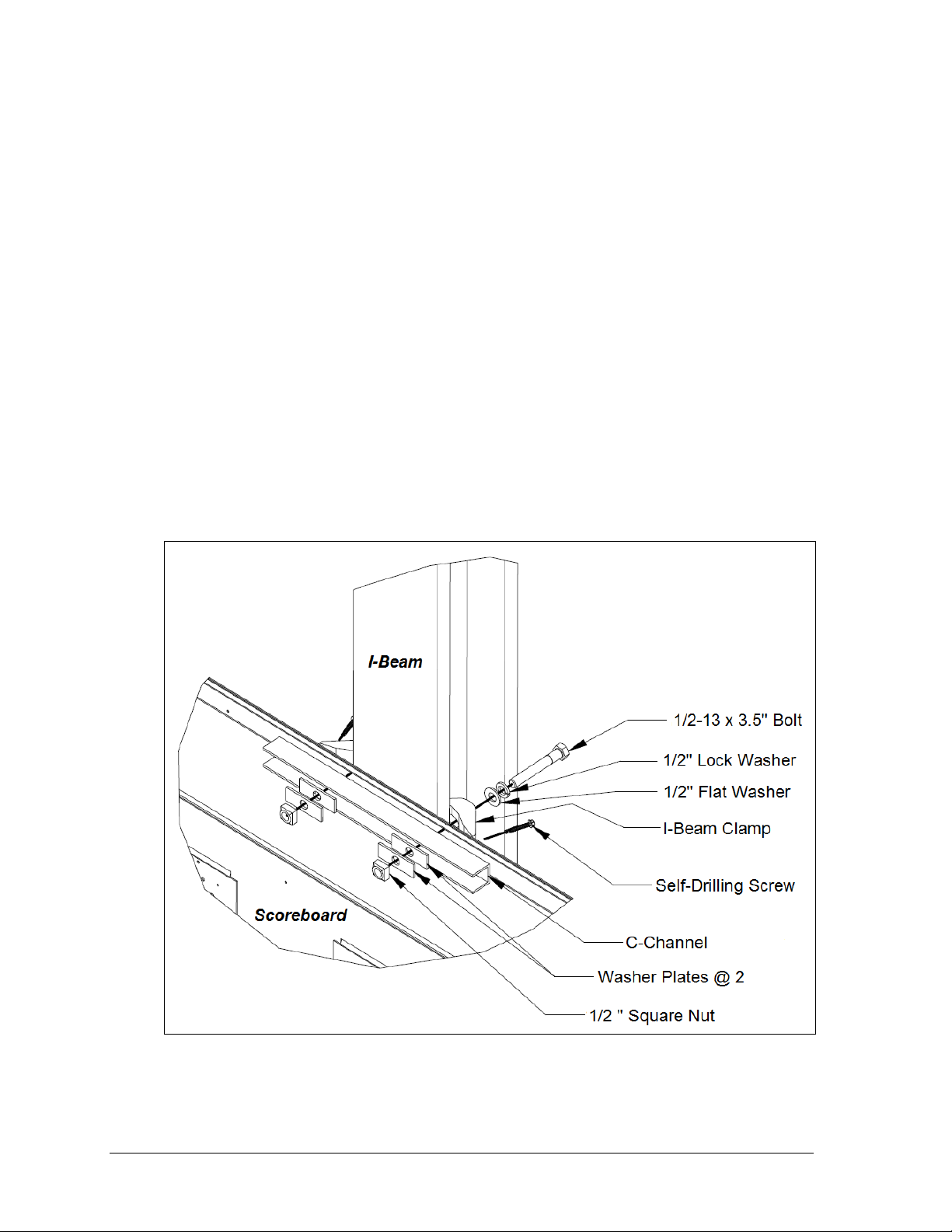
Figure 9: I-Beam Clamp Mounting Method, Front Rotated View
1. Position the scoreboard at the front of the beams, and lift it to the desired height.
2. Place a C-channel against the upper rear flange of the scoreboard next to each beam.
3. With the C-channel as a template, use a
9
/16" bit to drill holes in the upper rear flange
of the scoreboard cabinet where the rods will pass through. The rods should be as
close to the beam as possible.
4. Push the rods through the holes in the rear flange of the scoreboard cabinet and into
the C-channel, and then thread 1/2" square nuts onto the rods inside the C-channel.
5. Place clamping angles over each pair of rods and secure with
1
/2" lock washers and
hex nuts.
6. Make final adjustments in the positioning of the scoreboard to ensure it is flush and
level, and then firmly tighten all of the 1/2" hex nuts.
7. Repeat steps 2-6 for the lower rear flange of the scoreboard for every beam.
I-Beam Clamps
Mounting hardware includes C-channels; washer plates; I-beam clamps; 1/2-13 x 3.5" bolts;
self-drilling screws; and 1/2" square nuts, hex nuts, flat washers, and lock washers. Refer to
Figure 9 and Drawing A-1129110 in Appendix B.
Note: I-beams must have a flange thickness of 3/16" – 3/4". If flange is thicker than 3/4",
longer bolts will be required at added expense.
8 Mechanical Installation
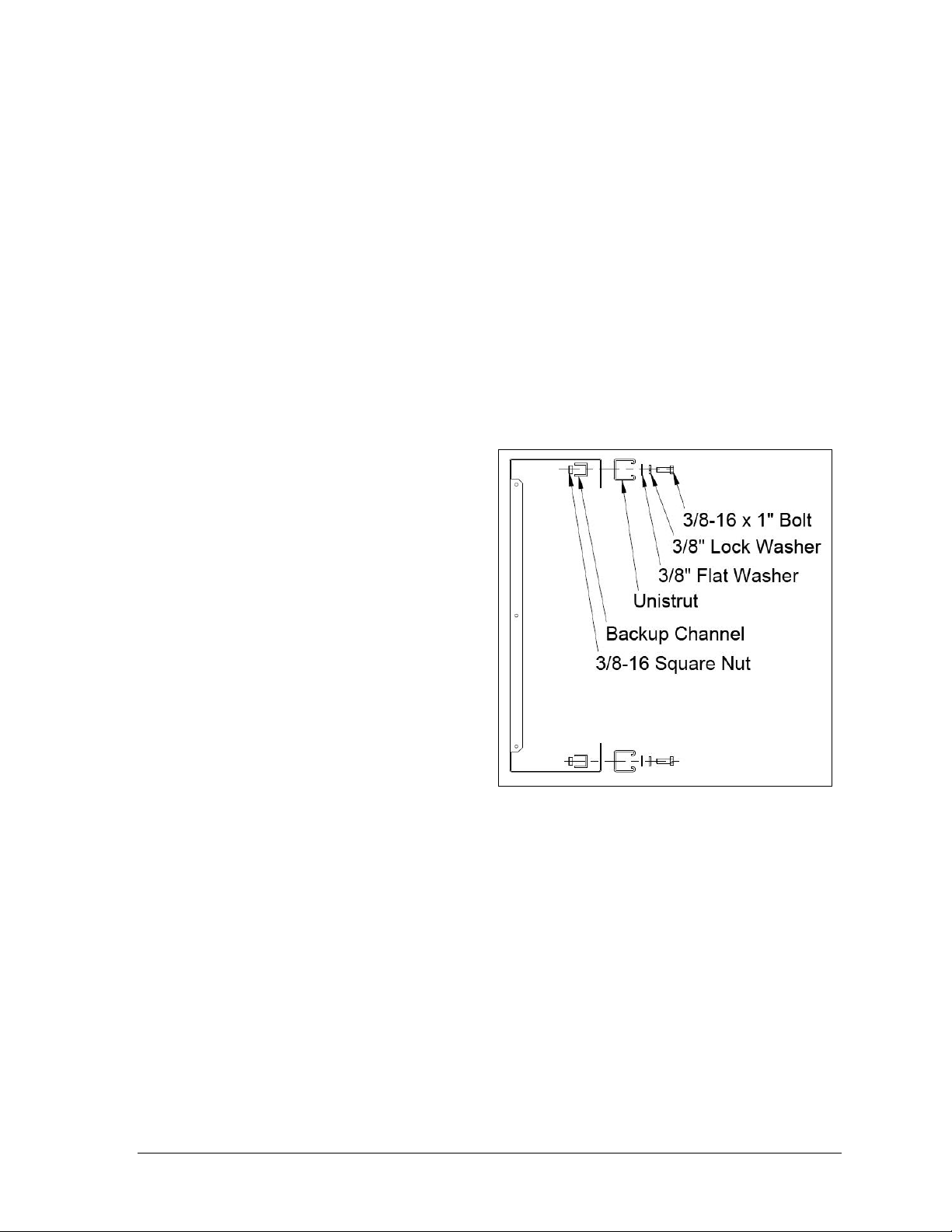
Figure 10: Unistrut Attachment, Side View
1. Position the scoreboard at the front of the beams, and lift it to the desired height.
2. Place a C-channel against the upper rear flange of the scoreboard next to each beam.
3. With the C-channel as a template, use a
of the scoreboard cabinet where the bolts will pass through. The bolts should be as
close to the beam as possible.
4. Slide a lock washer, flat washer, and I-beam clamp onto each bolt, then push the bolts
through the holes in the rear flange of the scoreboard cabinet and into the C-channel.
5. Place the 2 washer plates and
tighten the square nut onto the bolts.
6. Make final adjustments in the positioning of the scoreboard to ensure it is flush and
level, and then firmly tighten all of the bolts to 40 ft-lb torque.
7. Screw the self-drilling screws into the rear flange, snug up against the I-beam clamps.
8. Repeat steps 2-7 for the lower rear flange of the scoreboard for every beam.
2.4 Ad Panel Mounting
Unistrut Attachment
1. Using the backup channel as a
template, drill four 7/16" holes in
the upper and lower rear flanges
of the ad panel where the beams
will be located.
Note: Try to ensure that the two
center holes will be within the
width of the beam.
2. If the ad panel has backsheets,
remove them as needed to access
the ad panel interior.
3. Attach the piece of unistrut to the
ad panel with the included
hardware, as shown in Figure 10.
4. If any backsheets were removed,
put them back on at this time.
5. Place spring nuts into the unistrut. Twist the spring nuts until they are perpendicular
to the unistrut channel (refer to Figure 4 from Section 2.2).
Once the unistrut is attached and the spring nuts are in place, refer to the appropriate section
below for the type of mounting hardware provided with the ad panel.
9
/16" bit to drill holes in the upper rear flange
1
/2" square nuts inside the C-channel, and loosely
Mechanical Installation 9
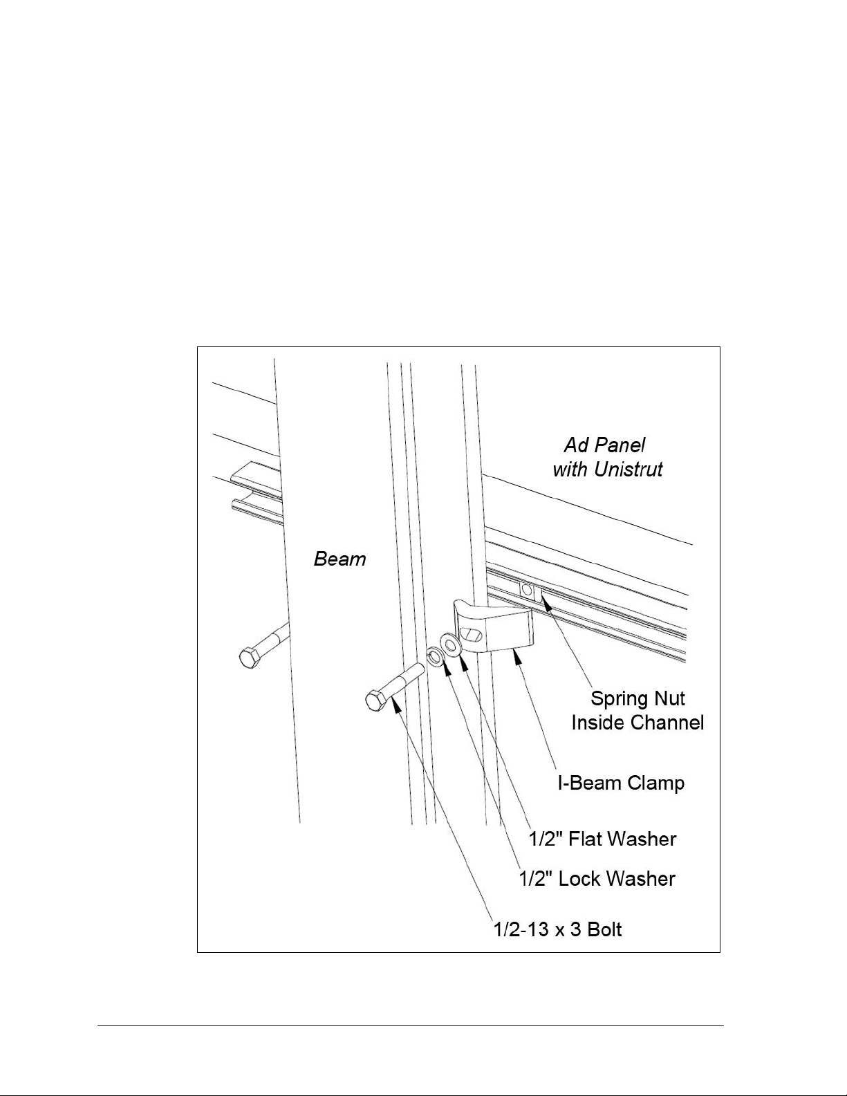
Figure 11: Ad Panel Mounting with I-beam Clamps, Rear Isometric View
I-Beam Clamps
Mounting hardware includes I-beam clamps, 1/2-13 x 3" bolts, 1/2" flat washers, and 1/2" lock
washers. Refer to Figure 11 and Drawing A-1052539 in Appendix B.
Note: I-beams must have a flange thickness of 1/4" – 3/4". If flange thickness is greater
than 3/4", longer bolts will be required at added expense.
1. Position the ad panel at the front of the beams, and lift it to the desired height.
2. Slide a lock washer, flat washer, and I-beam clamp onto the bolt, and loosely screw
the bolt into the spring nut.
3. Position each I-beam clamp assembly as close to the I-beam flanges as possible.
4. Make final adjustments in the positioning of the ad panel to ensure it is flush and
level, and firmly tighten all of the bolts.
10 Mechanical Installation
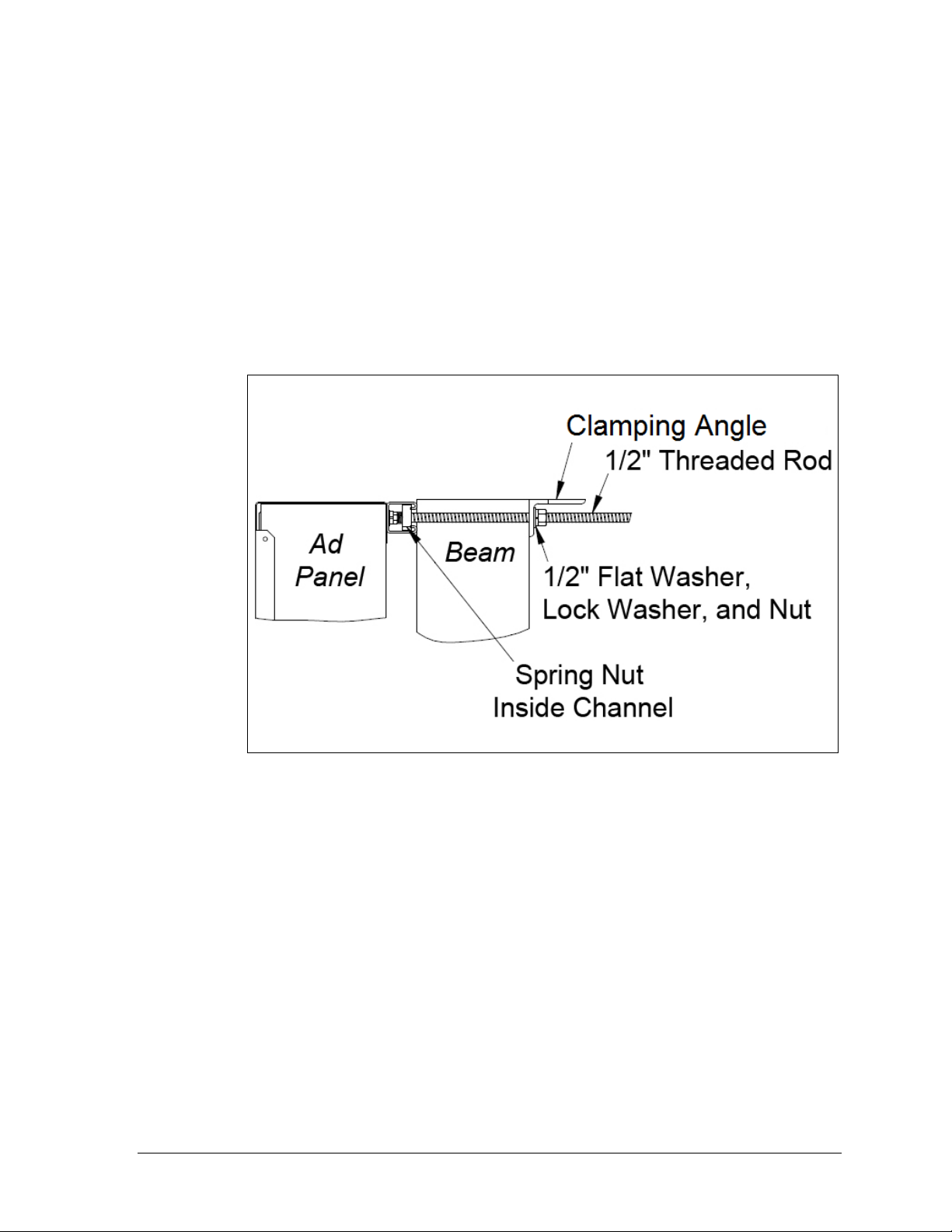
Figure 12: Ad Panel Mounting with Clamping Angles, Side View
Clamping Angles
Mounting hardware includes rear clamping angles; 1/2-13 x 24" threaded rods; and 1/2" nuts,
flat washers, and lock washers. Refer to Figure 12 and Drawing A-1052388 in Appendix B.
Note: The threaded rods do not pass through the beams; they run along both sides.
1. Screw a threaded rod into each of the spring nuts as far as it will go.
2. Position the ad panel at the front of the beams, and lift it to the desired height.
3. Slide clamping angles over the ends of the rods and loosely install the washers
and nuts.
4. Make final adjustments in the positioning of the ad panel to ensure it is flush and
level, and firmly tighten all of the 1/2" hex nuts.
2.5 Scoreboard Protective Devices
Daktronics makes optional protective devices, including screens and netting, to help prevent
damage to the scoreboard due to normal ball impacts.
Note: Some users install devices to protect the scoreboard from projectiles. Scoreboard
protection devices not provided by Daktronics must be approved by Daktronics prior to
installation. Failure to follow this approval procedure will void the scoreboard warranty.
Mechanical Installation 11

 Loading...