

Page 1
M SERIES OPERATIONS MANUAL
Page 2

M SERIES OPERATIONS MANUAL
Daktronics Automated Rigging System
Manufacturer’s contact info
7200 Rawson Road
Victor, New York 14564
tel 866-486-7835 585-924-5000
fax 585-924-0545
email sales@daktronics.com
web site www.daktronics.com/rigging
Page 3

TABLE OF CONTENTS
01 SAFETY INFORMATION 1
Warnings, Cautions, and Notes 1
Electrical Safety—General Warning 1
Included Safety Features 2
Manufacturer’s Name and Address 2
02 GENERAL INFORMATION 3
Motor and Electronic Variable Frequency Drive (VFD) 3
Hoist Assembly (Cable Drum, Load Brake, Limit Switches and Frame) 3
Vortek M Series Controller 4
Specifi cations 4
USA (60Hz) M Series Based Models and Applications 4
European (50Hz) M Series Based Models and Applications 5
Dimensions of Standard Unit 5
03 THEORY OF OPERATION 7
04 INITIAL OPERATION/MAIN SCREEN 9
Controls Layout 9
Turn On Operator Station 9
MAIN Screen Control Functions 9
User Access Levels 9
Changing Screens 9
Alarms 9
05 SYSTEM OVERVIEW SCREEN 11
SYSTEM OVERVIEW Screen Layout 11
06 HOIST OPERATION SCREEN 13
HOIST OPERATION Screen Layout 13
Selecting Hoists 13
JOG HOIST 13
Using Presets 14
07 CUEING SCREEN 15
CUEING Screen Layout 15
Cue Setup 15
Clear Current Cue Values 16
TABLE OF CONTENTS
i
Page 4

08 MACHINE CONFIGURATION SCREEN 17
MACHINE CONFIG. Screen Layout 17
CURRENT HOIST 17
CURRENT HOIST NAME 17
SOFT OPERATING LIMITS 17
HOME HOIST 17
LOADING LIMITS 18
Upper/Lower Limit Switches 18
09 PENDANT CONTROLLER 19
10 TROUBLESHOOTING 21
11 WARRANTY 23
ii
Page 5
01 SAFETY INFORMATION
Warnings, Cautions, and Notes
All Warning notes contained in this manual indicate information that may endanger personnel.
WARNING
The Daktronics rigging system is designed to raise and lower theatrical equipment under the rated hoist capacity
ONLY. This system is NOT designed to lift or lower personnel, and should never be used for that purpose.
Only trained and authorized personnel should be permitted to operate the Daktronics system. The unauthorized use,
alteration, or use for purposes other than those for which it was designed may cause injury to persons, damage to
the equipment, or create conditions which could lead to fatalities. All proper safety considerations must be observed.
While operating the Daktronics rigging system, a spotter must be used in conjunction with the user at all times. The
spotter must have a clear view of all moving elements while maintaining contact with the user. If an unsafe situation occurs, the
spotter must immediately signal the user to halt all movements until the environment is cleared of any person or obstruction.
All installation and maintenance involving the Vortek drive unit itself or the main electrical control cabinets will
require trained personnel. Simple daily maintenance activities such as cleaning of the touchscreen and the
M Series controller workstation may be carried out by the operators, and in most cases will be all that is needed
once installed.
Electrical Safety—General Warning
WARNING
Before working on any of the Vortek hoists, the main electrical disconnect must be
turned off and locked out according to OSHA regulations 29 CFR 1910.147.
The voltages used in the motor drive and master control panels can cause severe electrical
shock and/or burns. Extreme care is necessary at all times when working with the motor
drives. Only authorized personnel should carry out any installation, commissioning, or
maintenance of the electrical systems. All drive systems have been tuned at the factory
and will not require any additional alteration or adjustment by the owner’s personnel
unless specifically authorized by a Daktronics representative.
SAFETY INFORMATION
SAFETY INFORMATION
1
Page 6

Included Safety Features
Deadman Operation Movement Controls
Deadman controls only allow movement of hoists to commence and continue while the Execute Move
pushbutton is pressed. When the pushbutton is released all movement will come to a complete controlled
stop.
Emergency Stop
A red EMERGENCY STOP mushroom head pushbutton is located on each M Series control station. (There
may also be additional remote Emergency Stop locations installed). Pushing the button will disable all motor
drives through the Emergency Stop circuit and set all motor brakes. All motion of the attached loads on each
Vortek hoist immediately stops and inhibits all further movements until reset.
The Emergency Stops should ONLY be used for real emergencies or when required to disable the Daktronics
control system from inadvertent usage.
Vortek Back-Up Brake
This secondary mechanical braking system is designed to hold the rated load in the improbable case of
a failure of the primary motor brake or gearbox. This system is fully mechanical and acts independently of
any electrical inputs on the system.
Manufacturer’s Name and Address:
Daktronics
7200 Rawson Road
Victor, N.Y. 14564 USA
2
Page 7
02 GENERAL INFORMATION
WARNING
The Vortek® hoist system is an automated rigging system, meaning that the load is not counter-weighted. Each hoist
can lift loads only up to the design capacity. Overloading will result in electrical overload protection shut down of
the hoist and possible damage to rigging components.
Each hoist system consists of an integral electric motor driven gear reducer, directly coupled to a cable drum,
which winds steel cables (wire ropes) leading over sheaves installed within the hoist assembly and along the
structural steel of the building. The cables support battens for attaching the load. The battens can be lowered to
within the specified trim above the stage floor to allow attachment of loads.
The Vortek M Series control system consists of three basic parts, as described below:
Motor and Electronic Variable Frequency Drive (VFD)
The motor, Electronic Variable Frequency Drive, and dynamic braking resistor for each motor are located
within each Vortek M Series motorized hoist. A local control panel is located on each hoist for programming
and diagnostics by factory personnel. There is a reset-able circuit breaker located at each power point on the
HV wire way. The rated twist-locking plug on each unit acts as the main high voltage disconnect along with its
corresponding CB.
The Vortek batten hoists are not designed to raise and lower people.
These hoists should NEVER be used for this purpose.
Hoist Assembly (Cable Drum, Load Brake, Limit Switches, and Frame)
The Daktronics M Series control and hoist assemblies are usually mounted on the rigging steel at the top of the
stage house. Depending on design circumstances the Vortek M Series controlled hoists may be mounted in a
different location. The gear motor, helically grooved cable drum, support bearing, and frame structure are all
factory assembled and tested. Maximum upper height and minimum lower height are set by limit switches which
are adjusted by factory-trained personnel during installation and commissioning of the system. A position encoder
is located at the brake end of each hoist motor, attached directly to the motor shaft. Each hoist assembly is also
equipped with a LOAD BRAKE, a unique safety feature provided exclusively by Daktronics. This unit is designed
to engage automatically when the load is being lowered to greatly reduce any possibility of a loaded batten to
descend uncontrolled.
GENERAL INFORMATION
3
Page 8
Daktronics M Series Controller
Control of all hoists is possible from the M Series automation control console or, (depending on installation) a
pushbutton control station. The hoists can be controlled individually and at various speeds. Refer to Sections 4-9 of
this manual for the operating procedures.
WARNING
If it is necessary to operate a hoist from a location where the operator's view of the moving
load is obstructed, a second person must be used to observe the load and communicate to
the operator.
Specifications
WARNING
THE FOLLOWING MODELS ARE VARIABLE SPEED AND DESIGNATED TO BE CONTROLLED THROUGH
THE DAKTRONICS M SERIES CONTROLLER:
The Vortek M Series unit must only be used with a maximum load equal to the capacity stated for
the model below. Overloading the system may result in serious injury or an inoperable system.
USA (60Hz) M Series Based Models and Applications
M Series Controller- Single Purchase
HOIST MODEL NUMBER LOAD LBS (kg) SPEED FT/MIN (M/SEC)
VM-12180 0—1200 (540) 0—180 (0.9)
VM-14140 0—1400 (635) 0—140 (0.7)
VM-1740 0—1750 (793) 0—40 (0.2)
HM-4020 0—4000 (1814) 0—20 (0.1)
VM-2020 0—2000 (907) 0—20 (0.1)
VM-0820 0—800 (362) 0—20 (0.1)
4
Page 9

M Series Controller - Double Purchase
HOIST MODEL NUMBER LOAD LBS (kg) SPEED FT/MIN (M/SEC)
VM-12180-2 0—2400 (1088) 0—90 (0.45)
VM-14140-2 0—2800 (1270) 0—140 (0.7)
VM-1740-2 0—3500 (1586) 0—20 (0.1)
HM-4020-2 0—8000 (3628) 0—10 (0.05)
VM-2020-2 0—4000 (1814) 0—10 (0.05)
VM-0820-2 0—1600 (725) 0—10 (0.05)
Maximum travel distance is 62' (18.9 m) for Single Purchase Units, 31' (9.4 m) for Double Purchase Units.
European (50Hz) M Series Based Models and Applications
M Series Controller - Single Purchase
HOIST MODEL NUMBER LOAD kg SPEED M/SEC
EVM-0509 500 kg 0.9
EVM-0607 630 kg 0.7
EVM-0702 790 kg 0.2
EHM-1801 1810 kg 0.1
M Series Controller - Double Purchase
HOIST MODEL NUMBER LOAD kg SPEED M/SEC
EVM-0509-2 1000 kg 0.45
EVM-0607-2 1260 kg 0.35
EVM-0702-2 1580 kg 0.1
EHM-1801-2 3620 kg 0.05
Maximum travel distance is 62' (18.9 m) for Single Purchase Units, 31' (9.4 m) for Double Purchase Units.
Dimensions of Classic Unit
• Average weight of self-contained hoist module is 600 lb (272 kg).
• Height = 19.35" (49.15 cm)
• Length = 12' 9" (3.9 m)
• Width = 9" (22.9 cm) -- 6" (15.2 cm) centers can be achieved by positioning self-containing
hoist modules on opposite or opposing sides of the stage (stage right and stage left).
Dimensions of Heavy-Duty Unit
• Average weight of self-contained hoist module is 2100 lb (952 kg).
21
• Height = 3'-4
• Length = 15' (4.57 m)
• Width = 2' (60.96 cm)
/32" (1.03 m)
GENERAL INFORMATION
5
Page 10

03 THEORY OF OPERATION
Each Vortek® hoist is connected to the main high voltage power buss through a safety twist-locking plug. This plug
brings in the main 3-phase power that is connected to the motor drive and motor brake located in each hoist
assembly. Connected to each Vortek M Series hoist assembly through safety locking connectors are 24 V DC
power, Emergency Stop (E-Stop) circuit and a network cable.
The motor drive controls all movements of the hoist. Each drive on each hoist contains programming to identify it
to the network. This programming also includes but is not limited to maximum speed and acceleration. Each motor
drive monitors an incremental encoder, limit switches, load and emergency stop status. The incremental encoder
is used for position control and motor operation feedback. The limit switches are used for maximum up and down
travel. Load sensing is used for the detection of an under load or overload condition. The emergency stop status is
used to detect the operation of the emergency stop system.
Monitoring of each hoist is done over a CC-Link high performance industrial network using a Programmable
Logic Controller (PLC). The PLC is located in the operator station along with the PLC power supply, a Network
communications card, an I/O module and an optional module for communications to a handheld pendant. A 24
VDC power supply for the system is also located in the operator station.
The Human Machine Interface (HMI) that is mounted on the operator station allows the operator to perform
hoist movement through a combination of touchscreen selection and pressing of the EXECUTE MOVE button.
No movement will occur until the EXECUTE MOVE button is pressed. All hoist information is entered on the HMI
screens and then stored in the PLC. The HMI communicates to the PLC which in turn communicates to the hoists
over Network.
THEORY OF OPERATION
7
Page 11

04 INITIAL OPERATION/MAIN SCREEN
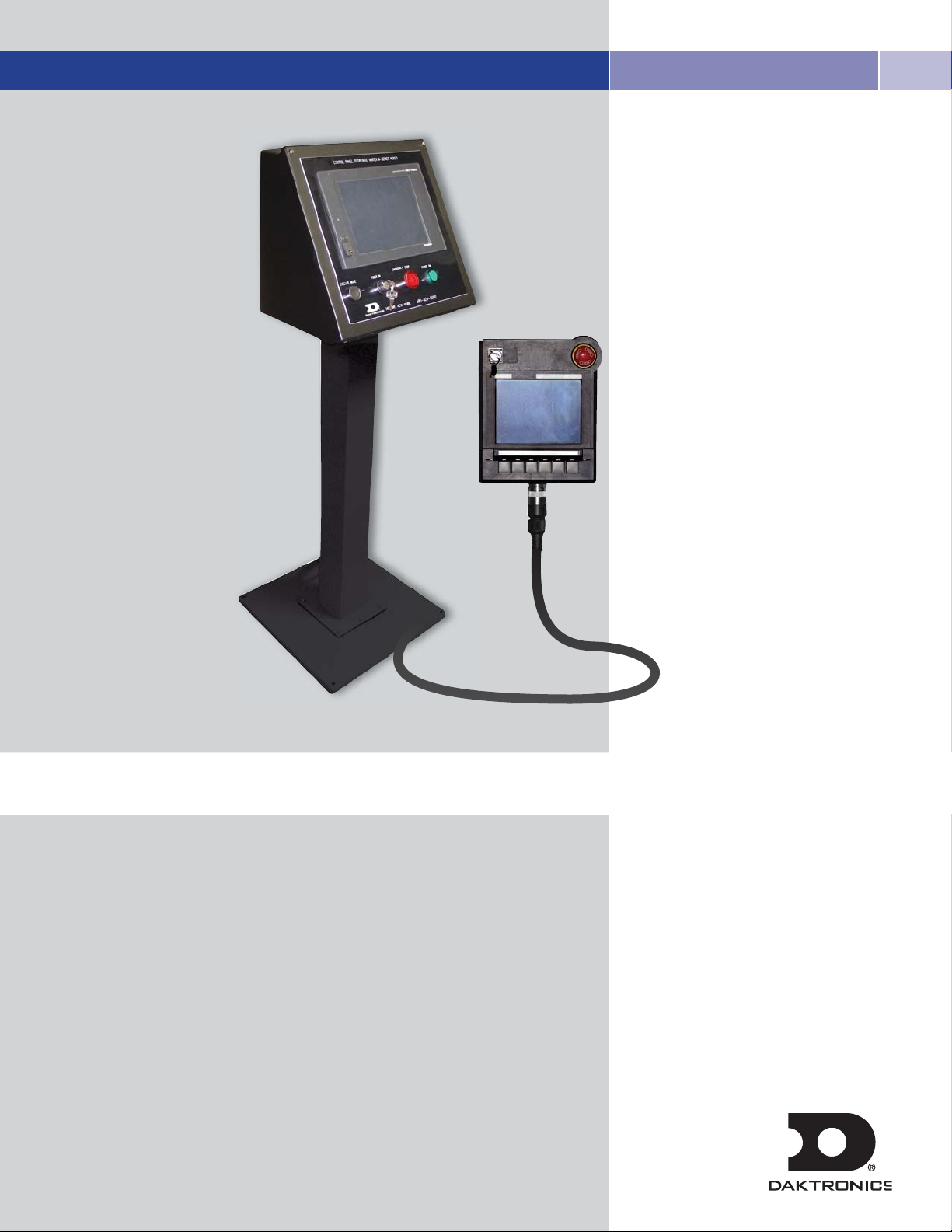
Controls Layout
All hoist operations are done through the operator station
HMI. The operator station consists of a touchscreen
monitor, EXECUTE MOVE button, POWER ON key switch,
EMERGENCY STOP button and a POWER ON light
(Figure 1).
Turn On Operator Station
Turn the key switch to the right.
MAIN Screen Control Functions
The MAIN screen (Figure 2) appears when the system
is first powered up. The system has to be logged on
to be able to select different screens. The user access
levels are described below.
There is also a CHANGE SCREEN LUMENS soft key
to change the screen brightness.
Figure 1: M Series Touchscreen Monitor
Figure 2: MAIN Screen
User Access Levels
Level 1 – Allows access to HOIST OPERATIONS and
SYSTEM OVERVIEW screens.
Level 2 -- Allows access to HOIST OPERATIONS,
SYSTEM OVERVIEW and CUEING screens.
Level 3 -- Allows access to HOIST OPERATIONS,
SYSTEM OVERVIEW, CUEING, MACHINE CONFIG.
and EDIT USER DATA screens.
Level 4 – Allows access to FACTORY CONFIG. screen.
All other screens can be accessed at this level.
Changing Screens
Changing to one of the other screens from the MAIN
screen is done by touching the appropriate button.
Alarms
An alarm bar is on the bottom of all screens to display
any alarms of the selected hoist. Touching the alarm
bar will bring up the alarm screen to display all current
alarms. The ALARM RESET button turns red if there is an
active alarm, otherwise it will remain orange. When the
button is red, press it to reset any VFD alarms.
INITIAL OPERATION/MAIN SCREEN
9
Page 12

05 SYSTEM OVERVIEW SCREEN
Figure 3: SYSTEM OVERVIEW Screen
SYSTEM OVERVIEW Screen Layout
The SYSTEM OVERVIEW screen (Figure 3) lets the user
view the following information for each hoist connected
to the system:
1. HOIST NAME
2. UPPER LIMIT
3. CURRENT POS. (position)
4. CURRENT LOAD
5. TARGET POS. (position)
6. TARGET SPEED
7. LOWER LIMIT
Up to 5 hoists are displayed on the screen at one
time. Click the NEXT button to view more.
SYSTEM OVERVIEW SCREEN
11
Page 13

06 HOIST OPERATION SCREEN
Figure 4: HOIST OPERATION Screen
HOIST OPERATION Screen Layout
The HOIST OPERATION screen (Figure 4) allows the
user to select a hoist, jog a hoist, set up, and run the
hoist to different preset positions and speeds.
This screen has the following information for each hoist
connected to the system:
1. CURRENT HOIST NAME
2. UPPER LIMIT
3. CURRENT POS. (position)
4. CURRENT SPD. (speed)
5. CURRENT LOAD
6. TARGET POS. (position)
7. TARGET SPEED
8. LOWER LIMIT
Selecting Hoists
Different hoists can be selected by using the PREVIOUS
HOIST or NEXT HOIST buttons or by pressing the
CURRENT HOIST number and entering the desired
hoist node number. Note that the node number may be
different from the line set number.
JOG HOIST
First select the desired hoist. Press the HOIST SPEED
button and enter the appropriate speed using the
on-screen keyboard. Press the JOG HOIST UP or JOG
HOIST DOWN button, depending on the direction the
hoist needs to go.
If the wrong jog option is mistakenly selected, simply
press and release the button to deselect that option.
The EXECUTE MOVE button must be pressed and held
to execute the move. If the EXECUTE MOVE button is
released, all hoist movements will stop.
HOIST OPERATION SCREEN
13
Page 14

Using Presets
a) Programming Presets
There are eight presets for each hoist. The presets are
programmed by selecting the POSITION and SPEED
buttons next to each of the eight presets and entering the
desired values using the on-screen keyboard.
b) Preset Operation
Only one preset can be selected at a time. In order to
run a hoist preset, the ENABLE PRESET MOVE button
must be selected. The desired SELECT PRESET button can
then be pressed.
The EXECUTE MOVE button must be pressed and held to
execute the preset move.
c) Clear Current Preset Values
Press Clear Current Preset Values to clear all
preset values to zero.
Press Yes to confirm or No to cancel (Figure 5).
Figure 5: Clear Current Preset Values
14
Page 15

Figure 6: CUEING Screen
Figure 7: Cue Operations Enabled
07 CUEING SCREEN
CUEING Screen Layout
The CUEING screen (Figure 6) allows the user to
program a cue with up to five hoists in the cue. The hoist
number and presets are used to program the cue. Up to
eight cues can be programmed.
Cue Setup
a. CUE NAME
Selecting the CUE NAME brings up an on-screen
keyboard that allows the user to enter a cue name of up
to 10 characters.
b. CURRENT CUE
This box displays the current active cue. Change to a
different cue using the PREVIOUS CUE and NEXT CUE
buttons or by pressing the current cue number and
entering the desired cue.
c. PRESET SELECTION
The cue is programmed by putting in the hoist node
number and entering the desired pre-programmed preset
for that hoist. The hoists must be entered in consecutively.
d. PRESET DATA
This shows the preset position that the hoist will move to
and the speed at which the hoist will move when the cue
is executed.
e. ACTUAL DATA
The actual data shows the current position and speed of
the programmed hoists.
f. ENABLE CUE OPERATIONS
To execute the cue once it is programmed, press the
ENABLE CUE OPERATIONS button. The button will
turn green and the text will change to CUE OPERATIONS
ENABLED (Figure 7).
The EXECUTE MOVE button must be pressed and held
until the cue is finished. If the EXECUTE MOVE button is
released, all hoist movements will stop.
CUEING SCREEN
15
Page 16

Clear Current Cue Values
Press Clear Current Cue Values to clear all
values of a cue.
Press Yes to confirm or No to cancel (Figure 8).
Figure 8: Clear Current Cue Values
16
Page 17

08 MACHINE CONFIGURATION SCREEN
MACHINE CONFIG. Screen Layout
The MACHINE CONFIG. screen (Figure 9) is where
the hoist limits can be changed, the hoist can be homed
for initial setup for full travel, and the load sensing can
be set up.
CURRENT HOIST
Change to a different hoist using the PREVIOUS HOIST
and NEXT HOIST buttons or by pressing the current hoist
number and entering the desired hoist.
CURRENT HOIST NAME
Selecting the CURRENT HOIST NAME brings up an
on-screen keyboard that allows the user to enter a hoist
Figure 9: MACHINE CONFIG. Screen
name of up to 10 characters.
SOFT OPERATING LIMITS
The soft operating limits are where the UPPER/LOWER
TRAVEL LIMITS are set, along with the MAXIMUM SPEED
and HOIST RATED LOAD LIMIT. These limits are
configured by Vortek Service personnel.
The OFFSET FROM FLOOR is also displayed. This value
can only be changed as part of the home down routine.
HOME HOIST
Homing of the hoists should only be done
by Daktronics Service personnel or under the
supervision of a Daktronics Service Person.
The homing routine is where the limit switches are set for
the travel of the hoists. Soft limits are configured as part
of the home routine along with the position calibration.
MACHINE CONFIGURATION SCREEN
17
Page 18
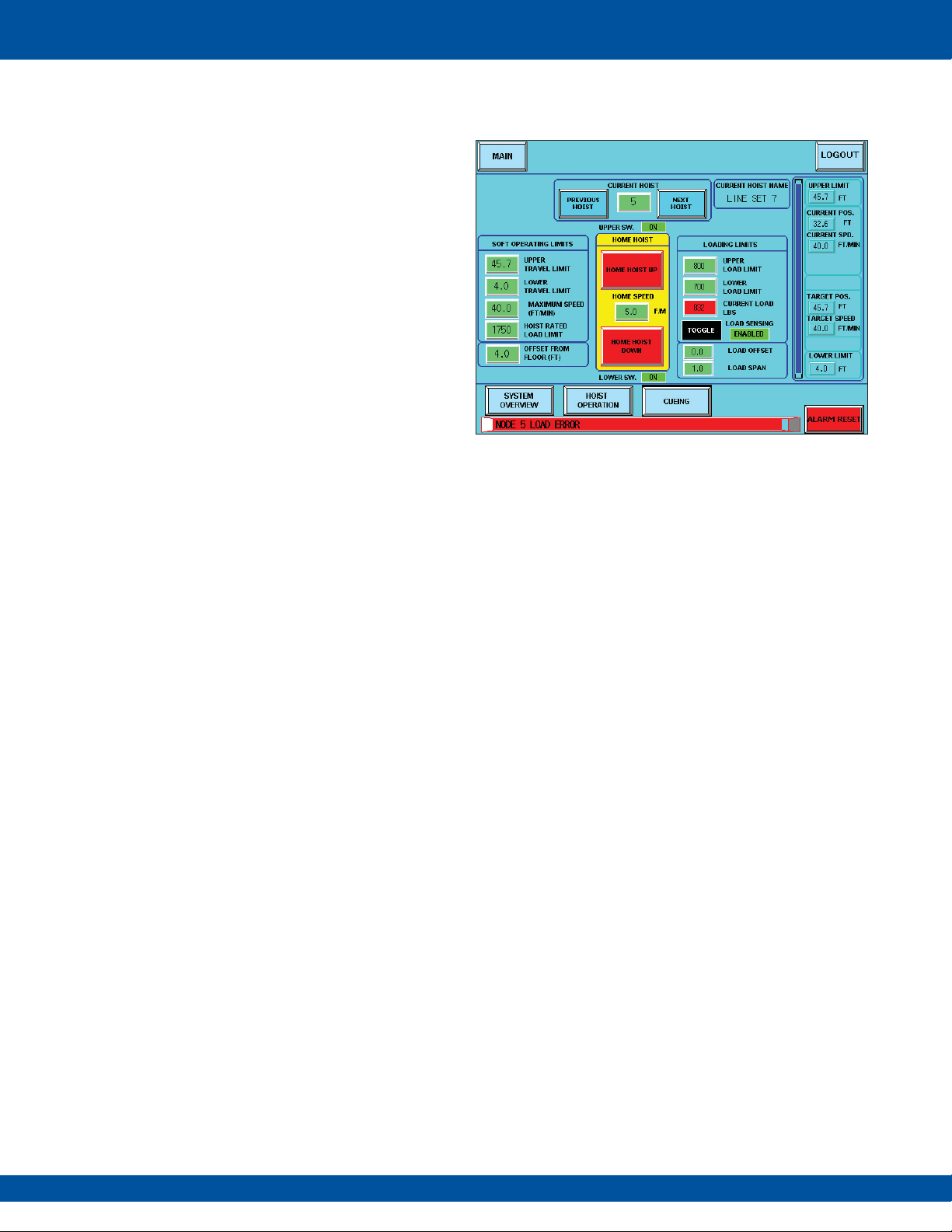
LOADING LIMITS
This is where the LOAD OFFSET and LOAD SPAN are
set up, along with the UPPER/LOWER LOAD LIMITS.
The span is normally set to “1.0” with the offset at “0.0”.
The upper and lower load limits should be set to a range
around the current load. For example if the load is 750
lbs, the upper limit might be set to 800 and the lower
limit to 700.
The CURRENT LOAD reading is displayed and the
LOAD SENSING can be set to ENABLED or DISABLED.
If the load sensing is enabled, the load value will turn
red if the load goes under or over the load limits.
An alarm will appear in the alarm bar (Figure 10).
This will also stop the hoist. It is up to the operator at that
point to see if the batten hung up on something to cause
the load shift. Once the load is back in range, the hoist
will function again, and the load reading will return back
to green.
Upper/Lower Limit Switches
The upper (UPPER SW.) and lower (LOWER SW.) limit
switch status is displayed above and underneath the
home up and down buttons. These should always show
“ON”. If one of the switches is off, then the hoist has
reached a limit switch, and an alarm stating this will be
displayed on the alarm bar.
Figure 10
: Load Sensing Enabled
18
Page 19
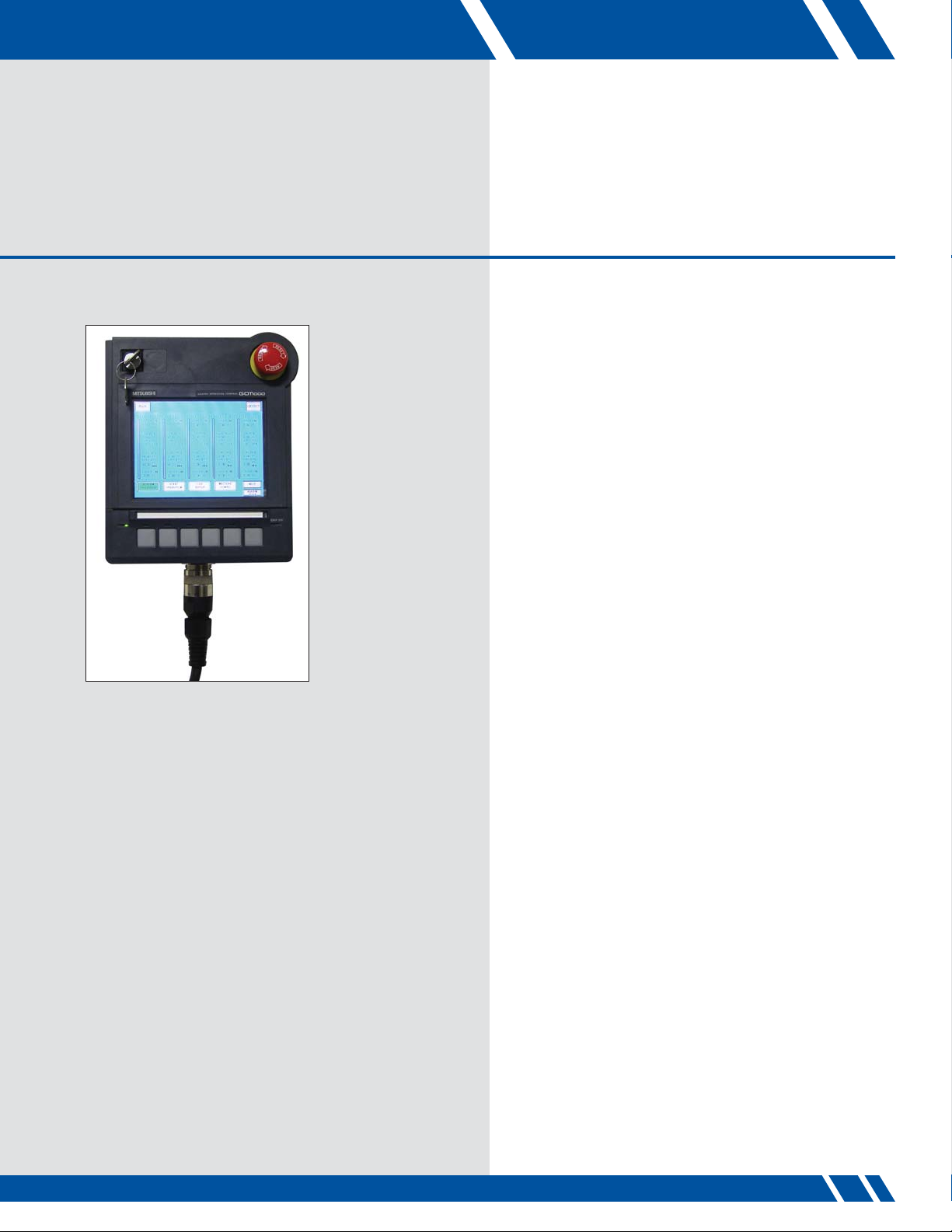
09 PENDANT CONTROLLER
The pendant controller mimics the functionality of the
main operator station. The key switch turns the pendant
controller on and off. The pendant has a mushroom
e-stop button and the lower left button of the pendant
is the EXECUTE MOVE button. If the user changes to a
different screen using the pendant, the main operator
station will also change to that screen, and vice versa.
Figure 11: Pendant Controller
PENDANT CONTROLLER
19
Page 20

10 TROUBLESHOOTING
SYMPTOM POSSIBLE CAUSE CORRECTIVE ACTION
Power failure Check incoming power to controller.
Controller is not on
Password will not work Forgot password
Key switch not turned on Turn key switch to ON.
Have administrator level user
log in and create new user
with new password.
EMERGENCY STOP button pressed
Hoist is faulted
Vortek hoist will not move
when commanded
Touchscreen not operating Dirty touchscreen
No network communications
(CC-Link fault)
E-Stop circuit not resetting 24 VDC power problem
Hoist has reached limit Check limit, readjust as necessary.
Overload/Underload fault condition
Preset information not set correctly or
there is no hoist speed set
Main high voltage power turned off
to hoists
Low voltage connector not connected
to hoist
Check all EMERGENCY STOP
buttons.
Check fault codes by pressing the
error bar at the bottom of the screen.
Reset hoist using reset button.
Check settings and reset parameters
if required. Refer to Section 8.
Set preset information and/or hoist
speed. Refer to Section 6.
Clean touchscreen with window
cleaner and soft cloth. Cycle power
to restart PLC and HMI.
Check to make sure high voltage to
hoists is turned on.
Check connection of low voltage wire
way connector to hoist.
Open controller and check for green
light on 24 VDC power supply.
Check 24 VDC power fuse.
TROUBLESHOOTING
21
Page 21

11 WARRANTY
The Daktronics Standard Warranty (the “Warranty”) sets forth the warranty provided by Daktronics with respect to the
Equipment. By accepting delivery of the Equipment, Purchaser agrees to be bound by and accept these terms and conditions.
All defined terms within the Warranty shall have the same meaning and definition as provided elsewhere in the Agreement.
DAKTRONICS WILL ONLY BE OBLIGATED TO HONOR THE WARRANTY SET FORTH IN THESE TERMS AND CONDITIONS
UPON RECEIPT OF FULL PAYMENT FOR THE EQUIPMENT.
1. Warranty Coverage
A. Daktronics warrants to the Purchaser that the Equipment will be free from Defects (as defined below) in materials and
Workmanship. Warranty period shall be for 15 months after date of shipment – parts and labor.
B. Daktronics’ obligation under this Warranty is limited to, at Daktronics’ option, replacing or repairing, any Equipment or
part that does not conform to the Equipment specifications. Unless otherwise directed by Daktronics, any defective part or
component shall be returned to Daktronics for repair or replacement. Daktronics may, at its option, provide on-site warranty
service. Daktronics shall have a reasonable period of time to make such replacements or repairs and all labor associated
therewith shall be performed during regular working hours. Regular working hours are Monday through Friday between
8:00 a.m. and 5:00 p.m. at the location where labor is performed, excluding any holidays observed by either Purchaser or
Daktronics.
C. Daktronics shall pay ground transportation charges for the return of any defective component of the Equipment. If returned
Equipment is repaired or replaced under the terms of this warranty, Daktronics will prepay ground transportation charges back
to Purchaser; otherwise, Purchaser shall pay transportation charges to return the Equipment back to the Purchaser. All returns
must be pre-approved by Daktronics before shipment. Daktronics shall not be obligated to pay freight for any unapproved
return. Purchaser shall pay any upgraded or expedited transportation charges.
D. Any replacement parts or Equipment will be new or serviceably used, comparable in function and performance to the
original part or Equipment, and warranted for the remainder of the Warranty Period. Purchasing additional parts or Equipment
from the Seller does not extend this Warranty Period.
E. Defects shall be defined as follows. A “Defect” shall refer to a material variance from the design specifications that
prohibit the Equipment from operating for its intended use. The Warranty does not provide for the replacement or installation
of communication methods including but not limited to, wire, fiber optic cable, conduit, trenching, or for the purpose of
overcoming local site interference radio equipment substitutions.
THIS LIMITED WARRANTY IS THE ONLY WARRANTY APPLICABLE TO THE EQUIPMENT AND REPLACES ALL OTHER
WARRANTIES OR CONDITIONS, EXPRESS OR IMPLIED, INCLUDING, BUT NOT LIMITED TO, THE IMPLIED WARRANTIES OR
CONDITIONS OF MERCHANTABILITY AND FITNESS FOR A PARTICULAR PURPOSE. SPECIFICALLY, EXCEPT AS PROVIDED
HEREIN, THE SELLER UNDERTAKES NO RESPONSIBILITY FOR THE QUALITY OF THE EQUIPMENT OR THAT THE EQUIPMENT
WILL BE FIT FOR ANY PARTICULAR PURPOSE FOR WHICH PURCHASER MAY BE BUYING THE EQUIPMENT. ANY IMPLIED
WARRANTY IS LIMITED IN DURATION TO THE WARRANTY PERIOD. NO ORAL OR WRITTEN INFORMATION, OR ADVICE
GIVEN BY THE COMPANY, ITS AGENTS OR EMPLOYEES, SHALL CREATE A WARRANTY OR IN ANY WAY INCREASE THE
SCOPE OF THIS LIMITED WARRANTY.
WARRANTY
23
Page 22

2. Exclusion from Warranty Coverage
The Warranty does not impose any duty or liability upon Daktronics for:
A. Any damage occurring, at any time, during shipment of Equipment unless otherwise provided for in the
Agreement. When returning Equipment to Daktronics for repair or replacement, Purchaser assumes all risk of loss or
damage, and agrees to use any shipping containers that might be provided by Daktronics and to ship the Equipment
in the manner prescribed by Daktronics;
B. Any damage caused by the unauthorized adjustment, repair or service of the Equipment by anyone other than
personnel of Daktronics or its authorized repair agents;
C. Damage caused by the failure to provide a continuously suitable environment, including, but not limited to: (i)
neglect or misuse, (ii) a failure or sudden surge of electrical power, (iii) improper air conditioning or humidity control,
or (iv) any other cause other than ordinary use;
D. Damage caused by fire, flood, earthquake, water, wind, lightning or other natural disaster, strike, inability to
obtain materials or utilities, war, terrorism, civil disturbance or any other cause beyond Daktronics’ reasonable
control;
E. Failure to adjust, repair or replace any item of Equipment if it would be impractical for Daktronics personnel to
do so because of connection of the Equipment by mechanical or electrical means to another device not supplied
by Daktronics, or the existence of general environmental conditions at the site that pose a danger to Daktronics
personnel;
F. Any statements made about the product by salesmen, dealers, distributors or agents, unless such statements are in
a written document signed by an officer of Daktronics. Such statements as are not included in a signed writing do not
constitute warranties, shall not be relied upon by Purchaser and are not part of the contract of sale;
G. Any damage arising from the use of Daktronics products in any application other than the commercial and
industrial applications for which they are intended, unless, upon request, such use is specifically approved in writing
by Daktronics; or
H. Any performance of preventive maintenance.
3. Limitation of Liability
Daktronics shall be under no obligation to furnish continued service under this Warranty if alterations are made to the
Equipment without the prior written approval of Daktronics.
The use of any non-Daktronics controller or software shall void the Warranty.
It is specifically agreed that the price of the Equipment is based upon the following limitation of liability. In no event
shall Daktronics (including its subsidiaries, affiliates, officers, directors, employees, or agents) be liable for any
special, consequential, incidental or exemplary damages arising out of or in any way connected with the Equipment
or otherwise, including but not limited to damages for lost profits, cost of substitute or replacement equipment, down
time, lost data, injury to property or any damages or sums paid by Purchaser to third parties, even if Daktronics has
been advised of the possibility of such damages. The foregoing limitation of liability shall apply whether any claim is
based upon principles of contract, tort or statutory duty, principles of indemnity or contribution, or otherwise.
In no event shall Daktronics be liable to Purchaser or any other party for loss, damage, or injury of any kind or nature
arising out of or in connection with this Warranty in excess of the purchase price of the Equipment actually delivered
to and paid for by the Purchaser. The Purchaser’s remedy in any dispute under this Warranty shall be ultimately
limited to the Purchase Price of the Equipment to the extent the Purchase Price has been paid.
24
Page 23

4. Dispute Resolution
Any dispute between the parties will be resolved exclusively and finally by arbitration administered in accordance with the rules
of the American Arbitration Association (“AAA”), except as otherwise provided below. The arbitration will be conducted before
a single arbitrator. The arbitration shall be held in Rochester, New York. Any decision rendered in such arbitration proceedings
will be final and binding on each of the parties, and judgment may be entered thereon in any court of competent jurisdiction.
This arbitration agreement is made pursuant to a transaction involving interstate commerce, and shall be governed by the Federal
Arbitration Act.
5. Governing Law
The rights and obligations of the parties under this warranty shall not be governed by the provisions of the United Nations
Convention on Contracts for the International Sales of Goods of 1980. Both parties consent to the application of the laws of the
State of New York to govern, interpret, and enforce all of Purchaser and Daktronics rights, duties, and obligations arising from, or
relating in any manner to, the subject matter of this Warranty, without regard to conflict of law principles.
6. Availability of Service Agreement
For Purchaser’s protection, in addition to that afforded by the Warranty, Purchaser may purchase extended services to cover the
Equipment. A Service Agreement is available from Daktronics and may provide for electronic parts repair and/or on-site labor
for an extended period from the date of expiration of this Warranty. Alternatively, a Service Agreement may be purchased in
conjunction with this Warranty for extended additional services. For further information, contact Daktronics Customer Service at
1-800.325.8766.
WARRANTY
25
Page 24

Daktronics
7200 Rawson Road Victor, New York 14564 USA
tel 866-486-7835 585-924-5000 fax 585-924-0545
www.daktronics.com/rigging email sales@daktronics.com
Copyright © 2010 Daktronics DD1829031 REV1 102210
 Loading...