

Page 1
MS-2013 Portable
LED Scoreboard
Display Manual
ED-13145 Rev 8 – 16 April 2015
201 Daktronics Drive PO Box 5128 Brookings, SD 57006-5128
Tel: 1-800-DAKTRONICS (1-800-325-8766) Fax: 605-697-4746
www.daktronics.com/support
Page 2

Page 3

ED-13145
Product 1192
Rev 8 – 16 April 2015
DAKTRONICS, INC.
Copyright 2007-2015
All rights reserved. While every precaution has been taken in the preparation of this manual, the publisher
assumes no responsibility for errors or omissions. No part of this book covered by the copyrights hereon may be
reproduced or copied in any form or by any means – graphic, electronic, or mechanical, including photocopying,
taping, or information storage and retrieval systems – without written permission of the publisher.
All Sport® and PanaView® are trademarks of Daktronics, Inc. Other trademarks used in this manual are the property of their
respective owners.
Page 4

Page 5

Table of Contents
Section 1: Introduction ................................................................................................................. 1
1.1 Specifications Label................................................................................................................. 1
1.2 Scoreboard Controllers ........................................................................................................... 1
1.3 Resources .................................................................................................................................. 2
1.4 Daktronics Nomenclature ...................................................................................................... 2
1.5 Product Safety Approval........................................................................................................ 2
Section 2: Specifications ............................................................................................................. 3
Section 3: Mechanical Installation .............................................................................................. 5
3.1 Cart Assembly ......................................................................................................................... 5
3.2 Adjusting the Cart ................................................................................................................... 5
3.3 Optional Equipment Installation ........................................................................................... 6
Caption Kits ...................................................................................................................... 6
Scoreboard Cover ............................................................................................................. 6
Ad Panel ............................................................................................................................ 6
Section 4: Electrical Operation .................................................................................................... 7
4.1 Power & Signal Access ........................................................................................................... 7
4.2 Power ........................................................................................................................................ 7
4.3 Signal ........................................................................................................................................ 8
Connecting Signal Cable ................................................................................................. 8
Base Station & Radio Receiver Installation ................................................................... 9
Setting the Base Station Function ............................................................................ 9
Setting the Radio Receiver Channel ....................................................................... 9
4.4 Power-On Self-Test (POST) ................................................................................................. 10
Radio Settings ................................................................................................................. 10
Section 5: Battery Care & Charging .......................................................................................... 11
5.1 On-Board Charger ................................................................................................................. 11
Operation ........................................................................................................................ 13
Charger Troubleshooting Table ................................................................................... 13
Radio Interference .......................................................................................................... 14
5.2 Battery & Charging Safety ................................................................................................... 14
Personal Safety Precautions .......................................................................................... 14
DC Connection Precautions .......................................................................................... 15
Section 6: Scoreboard Troubleshooting .................................................................................. 17
6.1 Troubleshooting Table .......................................................................................................... 17
6.2 Component Location & Access ........................................................................................... 19
6.3 Replacing Digits .................................................................................................................... 20
Segmentation & Digit Designation .............................................................................. 20
6.4 LED Driver ............................................................................................................................. 21
Replacing a Driver ......................................................................................................... 21
Setting the Driver Address ........................................................................................... 22
6.5 Replacing Batteries ................................................................................................................ 22
6.6 Horn ........................................................................................................................................ 23
Table of Contents i
Page 6

6.7 Replacement Parts ................................................................................................................. 23
Section 7: Daktronics Exchange and Repair & Return Programs .......................................... 25
7.1 Exchange Program ................................................................................................................ 25
Before Contacting Daktronics ....................................................................................... 25
7.2 Repair & Return Program .................................................................................................... 26
Shipping Address ........................................................................................................... 26
7.3 Daktronics Warranty and Limitation of Liability ............................................................. 26
Appendix A: Reference Drawings .................................................................................................. 27
Appendix B: Daktronics Warranty and Limitation of Liability .................................................... 29
ii Table of Contents
Page 7
Figure 1: Specifications Label
Section 1: Introduction
This manual outlines specifications, installation, and operating procedures for the Daktronics portable
LED scoreboard model MS-2013. For additional information regarding the safety, installation,
operation, or service of this system, refer to the telephone numbers listed in Section 7. Project-specific
information takes precedence over any other general information found in this manual.
IMPORTANT SAFEGUARDS
Read and understand all instructions before beginning the installation process.
Toggle the power switch to "OFF" when not using the scoreboard.
Disconnect the batteries and turn the power switch "OFF" when servicing the
scoreboard.
Do not modify the scoreboard structure or attach any panels or coverings to the
scoreboard without the express written consent of Daktronics.
Do not disassemble control equipment or electronic controls of the display; failure to
follow this safeguard will make the warranty null and void.
Do not drop control equipment or allow it to get wet.
1.1 Specifications Label
Power specifications as well as serial and model number information can be found on an ID
label on the display, similar to the one shown in Figure 1.
Please have the assembly number, model number, and the date manufactured on hand when
calling Daktronics customer service to ensure the request is serviced as quickly as possible.
Knowing the facility name and/or job number will also be helpful.
1.2 Scoreboard Controllers
The MS-2013 scoreboard is designed for use with the battery-powered RC-100 handheld
controller. The MS-2013 may also be controlled via an All Sport® 1600 series control console,
which may be equipped with an optional radio transmitter and powered by its own battery
pack for an alternate wireless scoring solution. Both controllers use keyboard overlays (sport
inserts) to control multiple sports. Refer to the following manuals for operating instructions:
All Sport 1600 Series Control Console Operation Manual (ED-12462)
Remote Control System RC-100 All Sport Operation Manual (ED-15133)
These control console manuals are available online at www.daktronics.com/manuals.
Introduction 1
Page 8
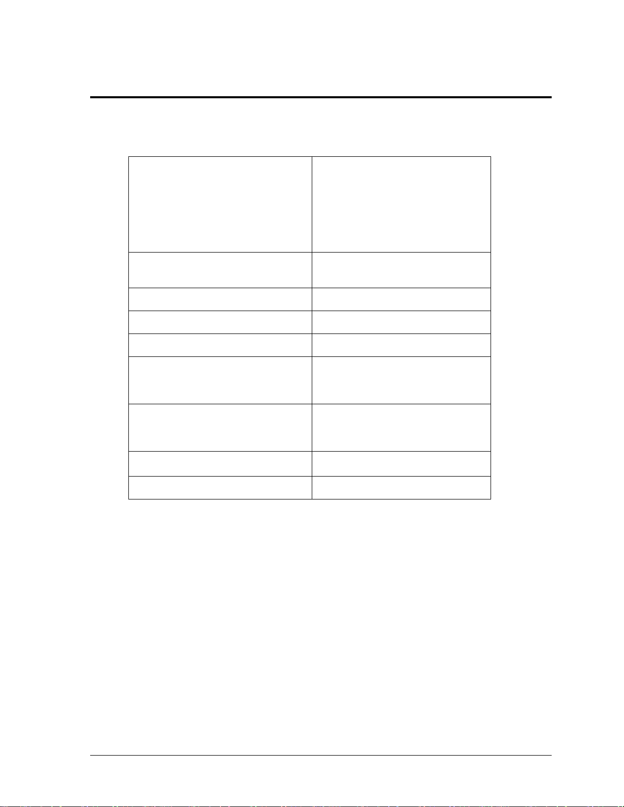
Main Component Labels
Part Type
Part Number
Individual circuit board
0P-XXXX-XXXX
Assembly; a collection of
circuit boards
0A-XXXX-XXXX
Wire or cable
W-XXXX
Fuse
F-XXXX
Transformer
T-XXXX
Metal part
M-XXX
Fabricated metal assembly
0S-XXXXXX
Specially ordered part
PR-XXXXX-X
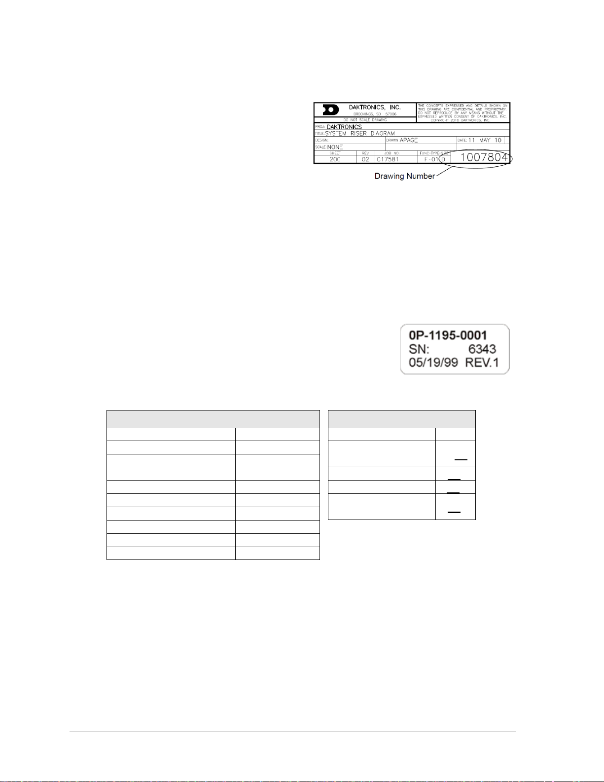
Figure 2: Daktronics Drawing Label
Figure 3: Typical Label
Accessory Labels
Component
Label
Termination block for
power or signal cable
TBXX
Grounding point
EXX
Power or signal jack
JXX
Power or signal plug
for the opposite jack
PXX
1.3 Resources
Figure 2 illustrates a Daktronics drawing
label. The drawing number is located in the
lower-right corner of a drawing. This
manual refers to drawings by listing the last
set of digits and the letter preceding them.
In the example, the drawing would be
referred to as Drawing C-1007804. Any
drawings referenced in a particular section
are listed at the beginning of it as shown below:
Reference Drawing:
System Riser Diagram ......................................................................................... C-1007804
Daktronics identifies manuals by the DD or ED number located on the cover page of each
manual. For example, this manual would be referred to as ED-13145.
1.4 Daktronics Nomenclature
Most components within this display carry a white label that lists
the part number of the unit. If a component is not found in the
Replacement Parts List in Section 6.7, use the label to order a
replacement. Figure 3 illustrates a typical label. The part number
is in bold.
Following the Replacement Parts List is the Daktronics Exchange Policy and the Repair &
Return Program. Refer to these instructions if replacing or repairing any display component.
1.5 Product Safety Approval
Daktronics outdoor scoreboards are ETL-listed, tested to CSA standards, and CE labeled.
Contact Daktronics with any questions regarding testing procedures.
2 Introduction
Page 9
Dimensions (Height, Width, Depth)
Display Only:
2'-10" H x 4'-4" W x 8" D
(864 mm, 1.32 m, 203 mm)
With Cart:
5'-2" H x 4'-4" W x 8" D
(1.57 m, 1.32 m, 203 mm)
Weight w/ Batteries & Cart
150 lb
(68 kg)
Digit Size
10" (254 mm)
Digit Color
Red
Watts
100 W
Power
120 VAC
or
24 V battery
Batteries
2 @ 12 V (each)
28 Amp/Hours
Amps per Line (Single Phase)
1 A
Driver Number & Address
A1 – 11
Section 2: Specifications
The table below lists all of the mechanical specifications, circuit specifications, and power
requirements for the MS 2013.
Note: Batteries require 12 hours to fully recharge and can operate for up to 14 hours of
normal use.
Specifications 3
Page 10

Page 11
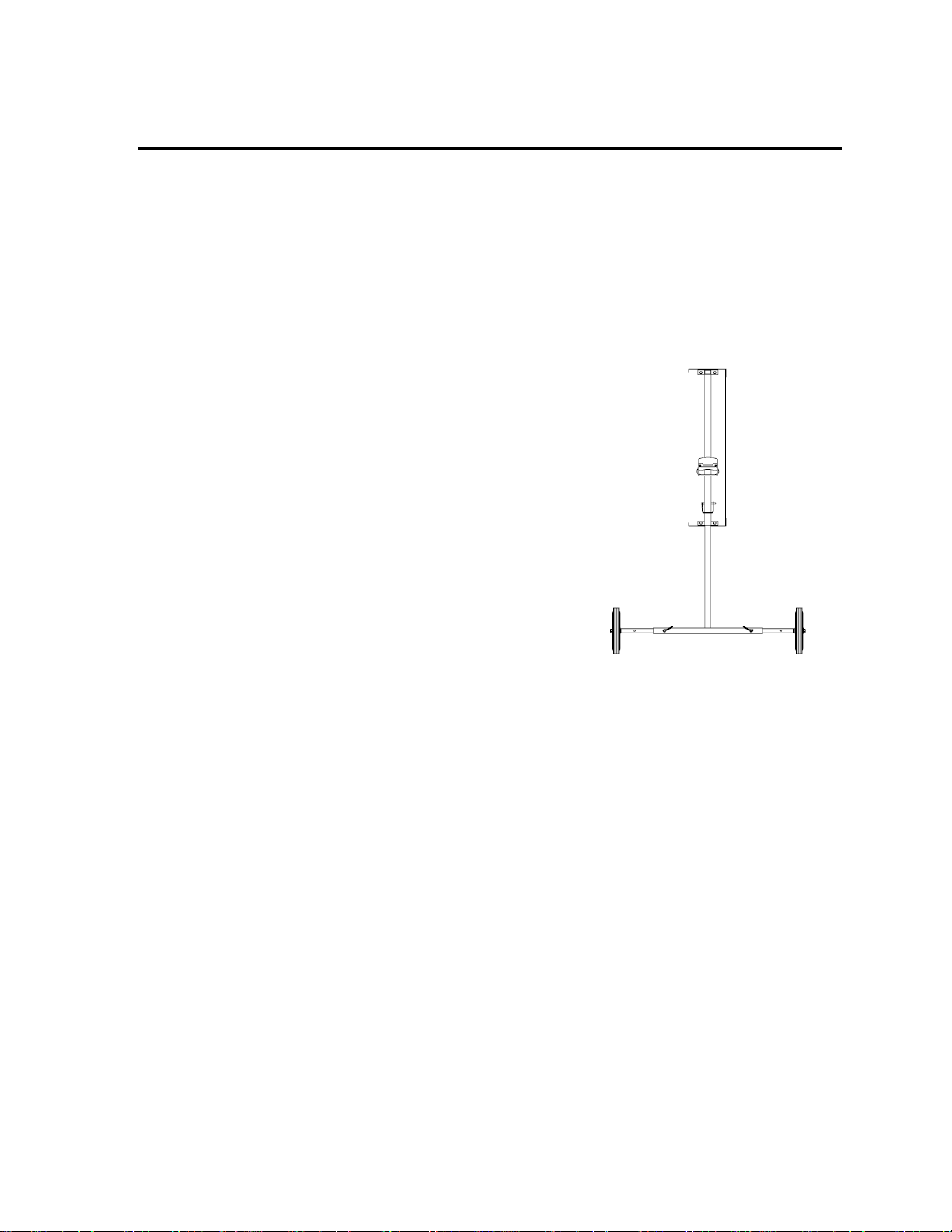
Figure 4: Cart Assembly, Side View
Section 3: Mechanical Installation
Mechanical installation involves assembly of the cart. The scoreboard itself requires no assembly or
permanent installation. Some assembly is required, however, for certain scoreboard options.
3.1 Cart Assembly
Reference Drawings:
Mechanical Specifications, MS-2013 .................................................................... A-159886
Cart Assembly ....................................................................................................... A-159889
The display cart, as shown in Figure 4, comes standard
with two wheels, but may use four if ordered. Open the
cart kit and verify the following pieces are included:
T-stands @ 2
Axle tubes @ 4
10" wheels @ 2 (or 4)
1
/2"-13 x 3 1/2" bolts @ 2 (or 4)
1
/2" flat washers @ 2 (or 4)
5
/16" diameter pins with clips @ 6
A 3/4" wrench will be needed to attach the wheels.
Refer to Drawing A-159889 in Appendix A and the
following instructions to assemble the cart:
1. Insert the axle tubes into the T-stands, and secure them with pins and retaining clips.
2. Mount the scoreboard by inserting the two T-stands into the larger tube attachments
on the sides of the scoreboard, and secure the stands with pins and retaining clips.
(The tubes mounted on either side of the scoreboard are permanent attachments; do
not remove them during cart disassembly.)
3. Mount the first wheel to one end of the T-stand, using a washer as a spacer, and
secure the wheel with an axle bolt. Repeat the process for the second wheel, and
tighten the bolts with a 3/4" wrench.
Note: Two more optional wheels may be installed on the opposite T-stand.
3.2 Adjusting the Cart
Drawing A-159886 in Appendix A shows the two axle positions that may be used with the
cart. The extended axle position provides maximum stability and is recommended for any
situation in which the scoreboard is raised. Use the narrow axle position (and lowest height)
to move the scoreboard through doorways and for storage. The drawing also illustrates front
profiles of the scoreboard in transport position and at maximum viewing height.
Mechanical Installation 5
Page 12

There are three height-adjustment holes in the support tubes on the sides of the scoreboard.
Raise the scoreboard for viewing by removing the pins and retaining clips, sliding the
scoreboard upward on the T-stands and reinserting the pins in the appropriate holes. Lower
the scoreboard for storage or transportation. It may be helpful to have one person lift the
scoreboard while another person adjusts the locking pins.
Caution! Do not raise the scoreboard in high winds or transport the scoreboard in the raised
position. These actions increase the likelihood of tipping over and damaging the scoreboard.
3.3 Optional Equipment Installation
Reference Drawings:
Caption Options, MS-2013 .................................................................................... A-159890
Cover Installation- MS-2013 .................................................................................. A-160060
Ad Panel Installation, MS-2013.............................................................................. A-160057
Caption Kits
The MS-2013 is shipped as a generic multisport scoreboard with a standard clock/score
caption arrangement. The face of the scoreboard displays game time, home and guest scoring,
and period. Four optional caption kits give the scoreboard added versatility:
Custom Team Names
Baseball/Softball Mode
Segment Timing Mode
Volleyball Mode
The aluminum caption panels are applied to the scoreboard face with hook-and-loop fastener
strips. They can be easily removed and replaced for various events, leaving the hook strips
attached to the face of the scoreboard. Refer to Drawing A-159890 in Appendix A for an
illustration of the various caption configurations.
Scoreboard Cover
The aluminum cover protects the MS-2013 during transportation and storage. Flanges on the
cover fit into slots on either side of the scoreboards, and the cover simply slides into place
using handles on the front. Drawing A-160060 in Appendix A illustrates the cover installation.
Note: If a radio antenna is installed on the face of the scoreboard it is highly recommended
to remove the antenna before installing or removing the cover. Refer to Section 4.3 for
more information about radio installations.
Ad Panel
A custom advertising/school logo panel may be added to the MS-2013. Threaded inserts in the
top of the scoreboard cabinet allow attachment using only three screws. The 12" H x 52" W
(305 mm, 1.32 m) aluminum panel runs the full width of the scoreboard. Drawing A-160057 in
Appendix A illustrates the ad panel installation.
6 Mechanical Installation
Page 13
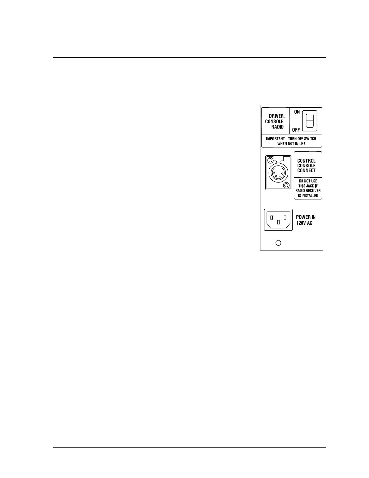
Figure 5: Control Panel
Section 4: Electrical Operation
The MS-2013 can be powered by two different electrical systems: a standard 120 VAC power source
and/or enclosed lead-acid batteries.
4.1 Power & Signal Access
Power and control connections for the MS-2013 are located in a
compartment on the rear of the scoreboard (Figure 5).
To open the rear compartment, turn the adjustable latch a quarterturn to the left. To close, shut the access door and turn the latch to
the right. If the latch will not engage because it is too tight, make
several turns to the left, and then turn back to the right to latch
and tighten.
The compartment is also designed for storage of the control
equipment. The compartment door can be closed with the power
and signal cords extending through the slot below the door.
Note: If the scoreboard came with a 100' (30.5 m) signal cable,
there will be two hooks on the rear of the scoreboard which
the cable may be wrapped around for storage.
4.2 Power
Reference Drawings:
Schematic: MS-2013-11 ........................................................................................ A-158030
Electrical Specifications, MS-2013 ........................................................................ A-159887
Battery Service, MS-2013 ..................................................................................... A-159891
Power for the scoreboard is provided in two ways: via standard 120 VAC line, or by means of
two sealed lead-acid DC batteries. Daktronics supplies two 12 V Panasonic® batteries (Model
LC-X1228P), rated at 28 ampere hours (A/H) as original equipment. Refer to Section 5 for
information on battery care and use of the on-board battery charger.
The provided 8' (2.4 m) 120 VAC power cord plugs directly into the POWER IN 120V AC
receptacle, located in the rear compartment on the back panel of the scoreboard (Figure 5).
Any time 120 VAC power is connected, the internal charger operates; however, the system
will not overcharge the batteries. When the power cord is not connected, the system runs on
battery power.
The MS-2013 is shipped ready for use. The battery charger is factory-mounted in the
scoreboard, and all internal wiring is in place and connected to the driver and batteries.
Electrical Operation 7
Page 14

The ON/OFF control switch (Figure 5) activates power to the internal scoreboard
components, as well as to the radio receiver or control console.
Turn the switch to ON for scoreboard operation.
At all other times, keep the switch in the OFF position.
Whether or not the scoreboard is operational, its batteries will continue to discharge any time
the switch is in the ON position. Leaving the switch ON when the unit is not in use could
completely discharge and damage the batteries.
Refer to Drawing A-159887 in Appendix A for component locations and illustrations of
internal and external wiring. Drawing B-158030 provides a detailed wiring schematic of
internal scoreboard components for advanced troubleshooting.
Daktronics recommends that the scoreboard remains plugged in to a 120 VAC power source
during storage. Battery life is enhanced by keeping the batteries fully charged. Typically,
batteries will be fully charged in about 12 hours and will give about 14 hours performance on
a full charge.
4.3 Signal
Reference Drawings:
System Riser Diagrams- MS-2013-11 ................................................................... A-160237
The MS-2013 can receive control signal three different ways, described below. Refer also to
Drawing A-160237 in Appendix A for diagrams of each of these control setups.
Setup 1 (Standard): A wireless RC-100 handheld controller communicates with a
radio base station installed inside the scoreboard.
Setup 2 (Optional): A 4-pin cable connects the scoreboard directly to the All Sport.
The cable transmits signal output to the scoreboard and power input to the controller.
Setup 3 (Optional): A control console equipped with radio transmitter and its own
battery pack or a separate power cord communicates with a radio receiver installed
inside the scoreboard.
Connecting Signal Cable
If the scoreboard was ordered with a wired control console, simply plug the signal cable into
the jack labeled CONTROL CONSOLE CONNECT (Figure 5) Attach the mating plug to the
modified power cord from the All Sport controller. Extension cables are also available from
Daktronics if more than the 100' (30.5 m) of control cable provided is needed.
8 Electrical Operation
Page 15

Base Station & Radio Receiver Installation
Reference Drawings:
Radio Receiver Installation, MS-2013 ................................................................... A-160015
Base Station: Outdoor Installation ......................................................................... A-236394
System Riser Diagram: RC-100- MS-2013 ........................................................... A-244926
Installation Drawing; Outdoor Scbd Gen VI Radio Receiver ............................... A-1109181
The RC-100 base station and All Sport radio receiver are typically held in place with
adhesive-backed, hook-and-loop fastener strips, and when ordered as original equipment
may already be installed. The only installation required is attachment of the radio antenna,
which may have been shipped separately to prevent damage.
If the base station or receiver is not already installed:
1. Access the inside of the scoreboard by removing the three (3) screws securing the rear
access panel and swinging it open.
2. Position the unit inside the scoreboard so the antenna connector can extend through
the hole in the upper-right corner on the front of the scoreboard.
3. Remove the backing from the fastener strips on the unit.
4. Insert the antenna jack through the hole, and then firmly press the unit against the
interior front panel, sticking the fastener's adhesive to the sheet metal.
5. Route and connect the cable protruding from the bottom of the unit to the mating 6-
pin jack directly on the LED driver.
Note: For models built prior to April 2015, the radio cable will connect to the 5-pin
jack labeled “J45” coming from the LED driver.
6. Close and secure the rear access panel.
7. From the front face of the scoreboard, note that the antenna connector now protrudes
through the panel.
a. Install and tighten the lock washer and nut on the antenna connector.
b. Mount the external antenna on the connector, turning the nut on the antenna
until it is snug.
c. Rotate the antenna so that it is pointing straight upward (it should look like a
capital “L” when viewed from the side).
Setting the Base Station Function
The base station is preset to Function 2 or 5, Channel 1. If the default settings do not appear to
work, refer to Drawings A-236394 and A-244926 for instruction on changing these settings.
For more information, refer to the RC-100 manual listed in Section 1.1.
Setting the Radio Receiver Channel
The radio receiver is preset to Channel 1. If there are other scoreboards in the facility
operating with radio signal, each scoreboard receiver must be set to a different channel
number (typically starting with 1 and numbering consecutively). Refer to Drawing A-1109181.
Refer to the Gen VI Radio Installation Manual (DD2362277) for more information.
This manual is available online at www.daktronics.com/manuals.
Electrical Operation 9
Page 16
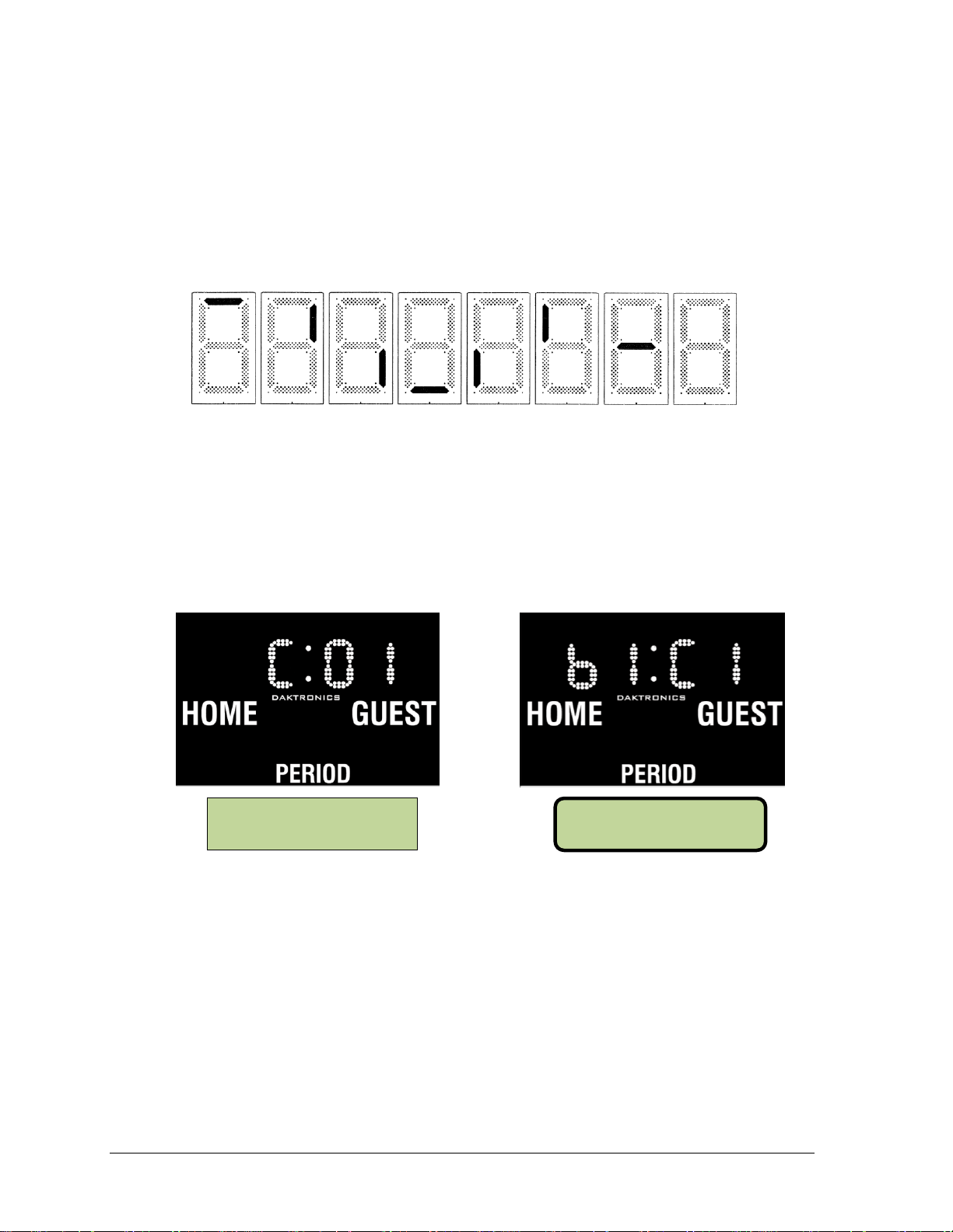
Figure 6: Digit Segment POST
RC-100 (Channel)
All Sport Radio (Broadcast & Channel)
Figure 7: Radio Settings
RA DI O S ETT I NGS
BC AST 1 CH AN 0 1
CONNECTI NG VI A
CH ANN EL O 1
4.4 Power-On Self-Test (POST)
The scoreboard performs a self-test each time that power is turned on and the control console
is powered off or not attached to the scoreboard. If the control console is attached and
powered on, the self-test does not run, and data from the control console is displayed on the
scoreboard after a brief period of time. Each scoreboard self-test pattern will vary depending
on the scoreboard model, the number of drivers, and types of digits. Figure 6 shows an
example of the LED bar test pattern that each digit performs.
Radio Settings
With an RC-100 base station installed, the channel settings (“C 01”) will be displayed in the
clock digits (Figure 7) during the POST. If an All Sport radio receiver is installed, both the
broadcast setting (“b1”) and the channel setting (“C1”) will be displayed. These values must
match the settings in the controller (refer to appropriate manual in Section 1.1).
10 Electrical Operation
Page 17

Charger Power Specifications
Outputs: two individual isolated outputs with
a combined rating as follows:
When charging:
When maintaining
6 A at 12 VDC
0.1 A at 13.3 VDC
Maximum recommended battery size:
For recharging:
Maintenance only
Up to 150 A/H
Up to 350 A/H
Input:
Rated AC voltage
Current draw
100-140 VAC, 50-60 Hz
1.6 A at full output
Figure 8: ChargePro Charger
Section 5: Battery Care & Charging
This section describes care and operation of the MS-2013 on-board battery charging system.
5.1 On-Board Charger
Reference Drawing:
Electrical Specifications. MS-2013 ........................................................................ A-159887
On a full charge, the two internal batteries provide enough power for approximately 14 hours
of normal operation. Keeping the batteries charged will help extend their life. Be sure that the
batteries are fully charged before storing the scoreboard during the off-season; storing the
scoreboard with a discharged battery can contribute to early battery failure. Daktronics
recommends keeping the scoreboard plugged in to a 120 VAC receptacle during storage.
The Guest® ChargePro on-board battery charger is designed both to recharge the batteries of
the scoreboards and to extend battery life in applications where scoreboard and batteries are
stored for long periods of time. The charger is located in the cabinet interior, attached to the
right side of the scoreboard back sheet (as viewed with the rear access panel open). The
charger is connected to the transformer next to the driver enclosure, and to the batteries.
Refer to Drawing A-159887 in Appendix A.
The charger, shown in Figure 8, is fully automatic and can
be connected to the twin 12 V lead-acid batteries
indefinitely without risk of overcharging. The 28 A/H
batteries provided with the scoreboard will typically be
fully recharged after about 12 hours.
The ChargePro is a three-stage, "smart" charger, and its
regulated output recharges the battery in the safest, fastest
way possible. Once a battery has been recharged, the
ChargePro supplies just enough electricity to compensate
for the charge a battery loses during storage. Unlike most
automotive "trickle" chargers, the unit will not boil off the
electrolyte in a lead-acid battery when left unattended.
Battery Care & Charging 11
Page 18

Scoreboard
Operating Condition
High Charge
Red ON
Green OFF
When just the red LED is on, it indicates that the batteries
are discharged and the charger is recharging them at the
BULK rate of 6 A (stage 1).
While the red LED is on, the voltage measured (with the
charger on) should be 11.8–14 V.
If the red LED stays on for more than 48 hours, refer to the
Charger Troubleshooting Table.
Medium Charge
Red ON
Green ON
When both the green and the red LEDs are on, the unit is
charging at an ABSORPTION rate of 2-6 A (stage 2).
This mode of charging gradually "tops off" the batteries
and reduces harmful sulfating.
While both LEDs are on, the voltage measured (with the
charger on) should be approximately 14 V.
If both LEDs stay on longer than 48 hours, refer to the
Charger Troubleshooting Table.
Float Charge
Red OFF
Green ON
When just the green LED is on, the unit is charging at a
FLOAT rate of less than 2 A (stage 3). The batteries are now
90 percent charged and ready for use.
This "float" charging current will gradually decrease to as
low as 0.1 A over the next day as the batteries reach 100
percent charge. They will now be kept at full charge without
overcharging.
If the green LED stays on and the battery is known to be low,
refer to the Charger Troubleshooting Table.
To operate the charger, simply plug the scoreboard's power cord into a standard 120 VAC,
60 Hz outlet. Red and green LED indicators on the charger, visible through holes on the
exterior back panel, indicate the recharging status. A label at this location also describes
charging levels.
Note: When the batteries are connected, they will continuously supply power to the
driver, even if the digits are blank. Make sure that the unit is switched ON only during
an event or when testing. At all other times, the switch should be in the OFF position.
The table below describes how the charger indicators operate:
12 Battery Care & Charging
Page 19

Problem
Cause
Solution
The charger does not seem
to be charging.
One or more defective/
damaged cells
One or more loose wire
connections
Charger has reduced its
output voltage due to a DC
overload or a DC short.
The internal AGX 15 A DC
output fuse has blown.
Test batteries and
replace if necessary
(see Section 6.5).
Check and tighten all
connections.
Remove the source of
the overload or short.
Contact Daktronics
Customer Service for
replacement.
It seems to take a long time
to recharge the batteries in
hot weather.
The charger has
overheated due to poor air
circulation and has
reduced its output.
Consider moving the
scoreboard to a shaded
location.
The red LED is always on.
or
The green LED never
comes on.
A dead short or an
overload
One or more bad cells in
battery
Too many batteries, or
battery is too large
A heavy DC load on the
battery while charging
Perform charger test:
1. Unplug the AC cord.
2. Remove the black
charger output wire
from the battery.
3. When AC power is
reapplied, only the
green LED should turn
on. If not, replace the
charger.
The green LED says on, but
the batteries do not charge.
Check charger's output
fuses.
If connections are
good, contact
Daktronics Customer
Service for
replacement.
Both the red and green
LEDs stay on all the time.
The battery is damaged or
unable to reach full charge.
Check electrolyte. Test/
replace the battery (see
Section 6.5).
Operation
If the ChargePro encounters a DC overload (excessive demand), it will reduce its output
voltage to a safe level to prevent damage. If the positive and negative connectors are touched
together, creating a short, the charger will instantly reduce its output voltage to nearly 0 V.
When the overload is removed, the charger automatically resumes normal operation.
If the in-line 10 A, 32 VDC fuse in either cable blows due to improper connection to a battery,
replace the fuse with an identical 10 A fuse only (Daktronics part # F-1006). Never replace a
blown fuse with a higher-value fuse.
The charger is waterproof, but the AC plug and DC bolt-type connectors should be kept dry.
It is normal for the charger to become warm during operation; consequently, it should not
contact any surface other than the scoreboard cabinet.
Charger Troubleshooting Table
Battery Care & Charging 13
Page 20

A DC component is
continuously drawing 3 A
or more, holding the
charger in its absorption
stage.
Disconnect any
accessories while
charging. If conditions
on board force the
charger to stay in
absorption stage for
several days, battery
damage may occur.
When AC power is applied,
neither LED turns on.
Confirm that all AC power
is available.
Internal failure
Reset AC power.
Contact Daktronics
Customer Service for
replacement.
The ground fault circuit
(GFCI) trips when charger is
on.
Problem with the AC outlet
Defective or oversensitive
charger
Check all connections
at the AC outlet.
Try a different outlet, or
replace the charger.
Radio Interference
The on-board battery charger generates and can radiate radio frequency energy. The
equipment has been tested and found to comply with the limits for a Class A digital device,
pursuant to FCC rules, Part 15.
With proper installation, there should be no interference with any radio communications,
either with the scoreboard's own receiver or other radio-controlled devices in the immediate
area. However, if it is determined that this device may be the cause of radio interference, try
to correct the interference with one or more of the following measures:
Reorient or relocate the receiving antenna.
Increase the separation between the equipment and the receiver.
Connect the equipment to an AC outlet on a circuit different from the receiver.
5.2 Battery & Charging Safety
Note: The following lists are general safety instructions when working with lead-acid
batteries. Some of the safety considerations are not applicable to the sealed batteries provided
with the MS-2013 as those batteries are self-contained and cannot be opened, and they are
safer than automotive batteries that require servicing. Exercise caution, however, when
working with any lead-acid battery.
Personal Safety Precautions
Someone should be within range of your voice or close enough to come to your aid
Have plenty of fresh water and soap nearby in case battery acid contacts your skin,
Wear complete eye protection and clothing protection. Avoid touching your eyes
14 Battery Care & Charging
If battery acid does contact skin or clothing, wash immediately with soap and water.
when you work near a lead-acid battery.
clothing, or eyes.
while working near the battery.
If you get acid in your eye, immediately flood the eye with running cold water for at
least 10 minutes, and get medical attention immediately.
Page 21

NEVER smoke or allow a spark or flame near the battery.
Be extra cautious while servicing the scoreboard to reduce the risk of dropping a tool
onto the battery. It might spark or short-circuit the battery or another electrical part,
which could cause an explosion.
Remove all personal metal items such as rings, watches, and other jewelry when
working with a lead-acid battery. A lead-acid battery can produce a short-circuit
current high enough to weld a ring or similar item to metal, causing severe burns.
Use the charger for charging LEAD-ACID batteries only. It is not intended to
recharge common dry cell batteries, which may burst and cause injury to people and
damage to property.
NEVER charge a frozen battery.
DC Connection Precautions
1. Check the polarity markings on the battery.
2. Attach the positive ring terminals (red or white wires with fuse) from each cable on
the charger to the positive (+) terminals of the batteries.
3. Attach the negative ring terminals (black wires) from each cable on the charger to the
negative (-) terminals of the batteries.
4. When disconnecting the charger, first disconnect (unplug) the AC power cord, then
remove the negative ring terminal from the battery's negative (-) terminal, and
remove the positive ring terminals last.
Battery Care & Charging 15
Page 22

Page 23

Problem
Possible Cause
Solution/Items to Check
Scoreboard doesn’t light
and console doesn’t work
No power to the scoreboard
Check that the scoreboard is
receiving 120 VAC power.
There may be a problem with the
batteries/charger. Refer to the
Charger Troubleshooting Table in
Section 5.
No power to console
Ensure the console is plugged into
the J31 jack labeled CONTROL
CONSOLE CONNECT or a 120
VAC power supply.
Exchange the console with a
working one, and enter the correct
sport code and/or radio settings to
test. Replace console if necessary.
Scoreboard digits don’t light,
but console works
No wired signal from console
Check that the scoreboard is
receiving 120 VAC or battery power.
Check that the red DS5 (or DS2)
LED on the driver lights up when
sending commands from the control
console (see Section 6.4).
No radio signal from console
Cycle power to the scoreboard and
watch for radio settings (see
Section 4.4).
Section 6: Scoreboard Troubleshooting
IMPORTANT NOTES:
1. Always disconnect power before doing any repair work on the scoreboard.
2. Permit only qualified service personnel to access internal display electronics.
3. Disconnect power when not using the scoreboard.
6.1 Troubleshooting Table
The table below lists potential problems with the scoreboard and indicates possible causes
and corrective actions. This list does not include every symptom that may be encountered,
but it does present several of the most common situations that may occur.
Many of the solutions offered below provide references to other sections within this manual
or to supplemental product manuals with further detail on how to fix the problem.
If a problem occurs that is not listed or that cannot be resolved using the solutions in the
following table, contact Daktronics using the information provided in Section 7.
Scoreboard Troubleshooting 17
Page 24

Problem
Possible Cause
Solution/Items to Check
Check that the green POWER and
amber RADIO IN RANGE indicators
on the radio receiver in the
scoreboard light up when the control
console is powered on. Keep the
console between 20-30' (6-9 m) from
the scoreboard.
Move the console 20-30' (6-9 m)
from the scoreboard and test again.
Verify that both the console and
scoreboard antennas are securely
tightened and in a vertical position.
Replace the radio receiver.
No signal to driver
Check that the scoreboard is
receiving 120 VAC or battery power.
Check that the red DS2 (or DS2)
LED on the driver lights up when
sending commands from the control
console (see Section 6.4).
Exchange the driver with a working
one of the same part #. Replace if
necessary (Section 6.4).
No power to driver
Check that the red DS8 (or green
DS1) LED on the driver is always lit
up when the scoreboard is powered
on (see Section 6.4).
Scoreboard digits light, but
not in the correct order
Incorrect sport code
Ensure the correct sport code is
being used for the scoreboard
model. Refer to the appropriate
control console manual.
Incorrect driver address
Check that the scoreboard driver is
set to the correct address (see
Section 6.4)
Scoreboard digits light,
console works, but no
display on scoreboard
No wired signal from console
(See solution on previous page)
No radio signal from console
(See solution on previous page)
Bad/damaged field wiring
Check that the red DS5 (or DS2)
LED on the driver lights up when
sending commands from the control
console (see Section 6.4)
Scoreboard works, but some
LEDs always stay on
Short in digit circuit
Exchange the digit with a working
one of the same part # to verify the
problem. Replace if necessary (see
Section 6.3).
Scoreboard works, but some
LEDs do not light or they
blink
Bad connection
Verify the connector on the back of
the digit circuit board is secure (see
Section 6.3).
18 Scoreboard Troubleshooting
Page 25

Problem
Possible Cause
Solution/Items to Check
Bad digit or driver
Exchange the digit/driver with a
working one of the same part # to
verify the problem. Replace if
necessary (see Section 6.3 for
digits or Section 6.4 for drivers).
Scoreboard works, but some
digits do not light
Bad digit or driver
(see solution above)
Incorrect sport code
(see solution on previous page)
Incorrect driver address
(see solution on previous page)
Wrong console controlling
scoreboard
Another console’s radio signal could
be transmitting to the scoreboard.
An example would be football and
baseball scoreboards that are within
1500' (457 m) of each other.
Radio interference
There may be other radio
transmissions in the area that
overpower the console. If it is not
possible to disable the interfering
device, It may be necessary to run a
wired signal connection instead.
6.2 Component Location & Access
Reference Drawing:
Electrical Specifications, MS-2013 ........................................................................ A-159887
In the MS-2013, the entire back panel is hinged on the right side (as viewed from the rear). To
gain access to the internal scoreboard components, simply remove the three screws securing
the back panel to the scoreboard cabinet, and swing it open. Drawing A-159887 in Appendix
A illustrates the back panel open and all of the internal components exposed.
Note: Disconnect power before servicing the scoreboard! Also turn power OFF when the
scoreboard is not in use. In addition to discharging the scoreboard batteries, prolonged
power-on may shorten the life of some electronic components.
Scoreboard Troubleshooting 19
Page 26

Figure 9: Digit Assembly
6.3 Replacing Digits
LEDs are embedded in a circuit board that is
mounted to the back of a single face panel,
as shown in Figure 9. Do not attempt to
remove individual LEDs. In the case of a
malfunctioning LED or digit segment,
replace the entire digit circuit board.
To replace a digit circuit board:
1. Open the back panel as described in
Section 6.2.
2. Disconnect the power/signal plug
from the back of the digit by
squeezing together the locking tabs
and pulling the connector free.
3. Use a
4. Position a new digit over the studs, making sure the rubber side of the rubber-backed
5. Tighten the nuts.
6. Reconnect the power/signal connector.
7. Close and secure the back panel, then power up and test the scoreboard to see if
9
/32" nut driver to remove the
nuts securing the digits to the inside
of the panel, and then lift the digit
off the standoff studs.
spacer is facing the digit circuit board.
Note: This is a keyed connector and it will attach in one way only. Do not attempt to
force the connection.
changing the digit has resolved the problem.
20 Scoreboard Troubleshooting
Segmentation & Digit Designation
Reference Drawings:
Segmentation, 7 Segment Bar Digit ........................................................................ A-38532
Electrical Specifications, MS-2013 ........................................................................ A-159887
In each digit, certain LEDs always go on and off together. These groups of LEDs are called
segments. Drawing A-38532 in Appendix A details which connector pin is wired to each
digit segment and the wiring color code used throughout the scoreboard.
Drawing A-159887 in Appendix A indicates the driver connectors controlling the digits.
The numbers shown in the upper half of a digit indicate which driver connector is wired to it.
Page 27

LED
Function
Operation
Summary
DS1
Radio/
RS-232 RX
Blinking
or off
DS1 will be blinking when the driver is receiving radio signal
and off when there is no signal.
DS2
Status
Blinking
DS2 will be blinking at one second intervals to indicate the
driver is running.
DS5
Signal RX
Blinking
or off
DS5 will be blinking when the driver is receiving current loop
signal and off when there is no signal.
DS8
Power
Steady on
DS8 will be on and steady to indicate the driver has power.
LED
Color
Function
Operation
Summary
DS1
Green
Power
Steady on
DS1 will be on and steady to indicate the driver
has power.
DS2
Red
Signal RX
Steady on
or blinking
DS2 will be on or blinking when the driver is
receiving a signal and off when there is no signal.
DS3
Amber
Status
Blinking
DS3 will be blinking at one second intervals to
indicate the driver is running.
6.4 LED Driver
The LED driver performs the task of switching digits on and off within the scoreboard.
LED drivers are located inside of a driver enclosure. Refer to Drawing A-159887 in Appendix
A to view the location and components of the driver enclosure.
When troubleshooting driver problems, several LEDs provide diagnostic information.
The number of LEDs and their function depends on the driver type.
Note: While it is necessary to have the scoreboard powered on to check the LED
indicators, always disconnect scoreboard power before servicing.
16-Column “Gyrus” Drivers
16-Column Drivers (prior to April 2015)
Replacing a Driver
1. Open the back panel as described in Section 6.2.
2. Remove the metal cover of the driver enclosure to expose the driver components.
3. Disconnect all connectors from the driver by squeezing together the locking tabs and
pulling the connectors free. It may be helpful to label the cables to know which cable
goes to which connector when reattaching the driver.
4. Remove the screws or nuts securing the driver to the inside of the enclosure.
5. Carefully lift the driver from the display and place it on a clean, flat surface.
6. Position a new driver over the screws and tighten the nuts.
7. Reconnect all power/signal connectors. Note that the connectors are keyed and will
attach in one way only. Do not attempt to force the connections.
8. Ensure the driver is set to the correct address (refer to Setting the Driver Address).
9. Close and secure the back panel, then power up and test the scoreboard to see if
changing the driver has resolved the problem.
Scoreboard Troubleshooting 21
Page 28

Figure 10: Driver Address Dials
Figure 11: Driver Address Dip Switch (prior to April 2015)
Setting the Driver Address
Since the same LED drivers can be used for many
scoreboard models, each driver must be set to receive
the correct signal input, or address, for the model
being used.
The MS-2013 will always be set to address 11.
Addresses are set through the S2 (L) and S3 (H) rotary
switches on the driver (Figure 10) using a small
flathead screwdriver. For address 11, set the
H switch to “0” and the L switch to “B”.
Note: For models built
prior to April 2015, the
driver address was set
via the S1 dip switch
(Figure 11) using a pen or
small, pointed object. For
address 11, set switches 1,
2, and 4 to ON.
6.5 Replacing Batteries
Reference Drawings:
Battery Service, MS-2013 ...................................................................................... A-159891
As the batteries age, they may lose capacity to sufficiently operate the scoreboard, even on a
full charge. When replacement becomes necessary, Daktronics recommends the same brand
battery installed as original equipment. Similar batteries may be used as long as they meet the
specifications for the scoreboard. If a different brand must be used, be sure that the terminals
are oriented the same as in the original to ensure a proper connection. Refer to Section 6.7 for
Daktronics replacement part numbers for batteries and fuses.
Drawing A-159891 in Appendix A illustrates battery service. Mounting brackets hold the
batteries in place at the bottom of the scoreboard. The bracket is designed to hold batteries
measuring 7" high, 6.5" wide, and 5" deep (178 mm, 165 mm, 127 mm). The bracket will not
support a battery of different dimensions.
To replace the batteries:
1. Open the back panel as described in Section 6.2.
2. Use a
3. Remove the screws securing the wires to the battery terminals.
4. Remove the battery from the scoreboard.
5. Reverse the procedure to install new batteries.
22 Scoreboard Troubleshooting
3
/8" socket or nut driver to unfasten the four nuts securing each battery bracket
to the scoreboard studs and remove the brackets.
Page 29

Description
Daktronics Part No.
12 VDC Horn Assembly
0A-1072-0023
Driver, 16-col outdoor LED
0A-1782-0100
Battery Monitor (Circuit Board)
0P-1192-0097
Digit, 10" red, 7-segment
0P-1192-0251
Battery; 12V, 28 A/H sealed lead-acid (Panasonic Model LC-X1228P)
BT-1023
Battery Charger; dual 12 or 24V, 3 A (Guest ChargePro Model 2607)
BT-1022
Fuse, AGC-10, 10A, 250 V glass tube
F-1006
Fuse, MDL-7, 7.5 A, 250 V glass tube
F-1031
Washer, ½ flat
HC-1095
Wheel Bolt, ½ -13 x 3 ½”
HC-1363
Wheel, 10x1.75, semi-pneumatic, 1/2" axle
RA-1007
Transformer, sec. 24 V @4A, pri. 115/230V, 50/60 Hz
T-1043
Power cord, 360º rotating, 8'
W-1181
Fuse holder
X-1287
Figure 12: Horn Mounting Detail, Side View
Important Notes:
During service, do not allow the battery terminals to touch any metal surface.
The batteries in these products contain lead. Do not dispose of the batteries in a
6.6 Horn
Reference Drawing:
Electrical Specifications, MS-2013 ........................................................................ A-159887
A 12 V buzzer horn is mounted in the upper-left
corner of the front face panel (as viewed from the
front). Drawing A-159887 in Appendix A shows
the horn location from the front as well as when
accessing internal components from the rear.
To replace a horn, simply disconnect the cable
running to it, and then remove the single nut and
washer holding the horn to the mounting bracket
(Figure 12).
Note: The horn volume is set at maximum during manufacturing and is not adjustable.
When reinstalling, make sure the terminal wires are connected correctly.
Improper connection may result in injury or damage to scoreboard components.
municipal waste system at the end of their useful life. Doing so may be a violation of
local, state, or federal environmental regulations. Please return the batteries to a
battery recycling center or battery retailer.
6.7 Replacement Parts
Refer to the following table for standard and optional replacement parts.
Scoreboard Troubleshooting 23
Page 30

Page 31

Market Description
Customer Service Number
Schools (including community/junior colleges), religious
organizations, municipal clubs and community centers
877-605-1115
Universities and professional sporting events, live events
for auditoriums and arenas
866-343-6018
Section 7: Daktronics Exchange and Repair &
Return Programs
7.1 Exchange Program
The Daktronics Exchange Program is a service for quickly replacing key components in need
of repair. If a component fails, Daktronics sends a replacement part to the customer who, in
turn, returns the failed component to Daktronics. This decreases equipment downtime.
Customers who follow the program guidelines explained below will receive this service.
Before Contacting Daktronics
Identify these important numbers:
Display Serial Number: _________________________________________________________
Display Model Number: _________________________________________________________
Job/Contract Number: __________________________________________________________
Date Installed: _________________________________________________________________
Daktronics Customer ID Number: ________________________________________________
To participate in the Exchange Program, follow these steps:
1. Call Daktronics Customer Service.
2. When the exchange part is received, mail the old part to Daktronics.
If the replacement part fixes the problem, send in the problem part being replaced.
a. Package the old part in the same shipping materials in which the replacement
part arrived.
b. Fill out and attach the enclosed UPS shipping document.
c. Ship the part to Daktronics.
3. The defective or unused parts must be returned to Daktronics within 5 weeks of
initial order shipment.
If any part is not returned within five (5) weeks, a non-refundable invoice will be
presented to the customer for the costs of replenishing the exchange parts inventory
with a new part.
Daktronics reserves the right to refuse parts that have been damaged due to acts of
nature or causes other than normal wear and tear.
Daktronics Exchange and Repair & Return Programs 25
Page 32

7.2 Repair & Return Program
For items not subject to exchange, Daktronics offers a Repair & Return Program. To send a
part for repair, follow these steps:
1. Call or fax Daktronics Customer Service:
Refer to the appropriate market phone number in the chart on the previous page.
Fax: 605-697-4444
2. Receive a case number before shipping.
This expedites repair of the part.
3. Package and pad the item carefully to prevent damage during shipment.
Electronic components, such as printed circuit boards, should be placed in an
antistatic bag before boxing. Daktronics does not recommend using packing ‘peanuts’
when shipping.
4. Enclose:
name
address
phone number
the case number
a clear description of symptoms
Shipping Address
Daktronics Customer Service
[Case #]
201 Daktronics Drive, Dock E
Brookings, SD 57006
7.3 Daktronics Warranty and Limitation of Liability
The Daktronics Warranty and Limitation of Liability is located in Appendix B. The Warranty
is independent of Extended Service agreements and is the authority in matters of service,
repair, and display operation.
26 Daktronics Exchange and Repair & Return Programs
Page 33

Appendix A: Reference Drawings
Drawing Title Drawing Number
Segmentation, 7 Segment Bar Digit ........................................................................................... A-38532
Schematic: MS-2013-11 ........................................................................................................... B-158030
Mechanical Specifications, MS-2013 ........................................................................................ A-159886
Electrical Specifications, MS-2013 ........................................................................................... A-159887
Cart Assembly, MS-2013 .......................................................................................................... A-159889
Caption Options, MS-2013 ....................................................................................................... A-159890
Battery Service, MS-2013 ......................................................................................................... A-159891
Radio Receiver Installation- MS-2013 ...................................................................................... A-160015
Ad Panel Installation, MS-2013 ................................................................................................. A-160057
Cover Installation- MS-2013 ..................................................................................................... A-160060
System Riser Diagrams- MS-2013-11 ...................................................................................... A-160237
Base Station: Outdoor Installation ............................................................................................ A-236394
System Riser Diagram: RC-100- MS-2013............................................................................... A-244926
Installation Drawing; Outdoor Scbd Gen VI Radio Receiver .................................................. A-1109181
Reference Drawings 27
Page 34

Page 35

Page 36

'$7(5(9 %<
'$7(5(9 %<
'$7(5(9 %<
'$7(5(9 %<
'$7(5(9 %<
5(3/$&('$:,7+:5(029('3$57180%(56
'$7(5(9 %<
0$5 5$$
)(% =6:
)520/(''5,9(5
3(5(&&255(&7('6:,7&+180%(5127$7,2121
'$7(5(9 %<
'5,9(532:(56:,7&+
'$7(5(9 %<
'$7(5(9 %<
Page 37

Page 38

DAKTRONICS
PERIOD
GUESTHOME
DAKTRONICS
CONNECT
CONSOLE
120V AC
POWER IN
CONTROL
OFF
ON
DRIVER,
CONSOLE,
RADIO
IMPORTANT NOTICE
RECYCLE THE BATTERIES
CONNECT
CONSOLE
WHEN NOT IN USE
IMPORTANT - TURN OFF SWITCH
120V AC
POWER IN
CONTROL
OFF
ON
DRIVER,
CONSOLE,
RADIO
CHARGE STATUS LIGHTS
THE CONCEPTS EXPRESSED AND DETAILS SHOWN ON THIS
DRAWING ARE CONFIDENTIAL AND PROPRIETARY. DO NOT
REPRODUCE BY ANY MEANS WITHOUT THE EXPRESS
WRITTEN CONSENT OF DAKTRONICS, INC.
COPYRIGHT 2015 DAKTRONICS, INC.
DAKTRONICS, INC.
AV
DRAWN: DATE:
SHEET JOB NO:REV
SCOREBOARDS
ELECTRICAL SPECIFICATIONS- MS-2013
A VANBEMMEL 11 DEC 01
P1192 R
04 A
1=20
AVB
159887
07
Page 39

Page 40

DAKTRONICS
GUESTHOME
SET INNING
SETS WON SETS WON
OUTBALL STRIKE
GUEST
PERIOD
DAKTRONICS DAKTRONICS
HOME GUEST
DAKTRONICS
DAKTRONICS
PERIOD
GUESTHOME
THE CONCEPTS EXPRESSED AND DETAILS SHOWN ON THIS
DRAWING ARE CONFIDENTIAL AND PROPRIETARY. DO NOT
REPRODUCE BY ANY MEANS WITHOUT THE EXPRESS
WRITTEN CONSENT OF DAKTRONICS, INC.
COPYRIGHT 2014 DAKTRONICS, INC.
DAKTRONICS, INC.
AV
DRAWN: DATE:
SHEET JOB NO:REV
OUTDOOR LED DIGIT SCOREBOARDS
CAPTION OPTIONS- MS-2013
A VANBEMMEL 10 DEC 01
P1192 R
08 A
1=20
AVB
159890
01
DATE:REV BY:
01 17 JUL 14 KDD
REPLACED 'GAMES WON' AND 'GAME' WITH
'SETS WON' AND 'SET'
REMOVED 'INTERVAL' CAPTION
Page 41

THE CONCEPTS EXPRESSED AND DETAILS SHOWN ON THIS
DRAWING ARE CONFIDENTIAL AND PROPRIETARY. DO NOT
REPRODUCE BY ANY MEANS WITHOUT THE EXPRESS
WRITTEN CONSENT OF DAKTRONICS, INC.
COPYRIGHT 2015 DAKTRONICS, INC.
DAKTRONICS, INC.
AV
DRAWN: DATE:
SHEET JOB NO:REV
SCOREBOARDS
BATTERY SERVICE- MS-2013
A VANBEMMEL 11 DEC 01
P1192 R
04 A
1=16
AVB
159891
04
Page 42

HOME GUEST
PERIOD
DAKTRONICS
NOTES:
IF THERE ARE TO BE MULTIPLE SCOREBOARD RECEIVERS AND MULTIPLE CONTROL CONSOLES
OPERATING IN THE AREA, REFER TO RADIO INSTALLATION MANUAL(S) TO CHANGE THE CHANNEL
NUMBER ON THE RECEIVER PRIOR TO INSTALLING.
REMOVE THE THREE SCREWS SECURING THE BACK OF THE MS-2013, AND SWING IT OPEN.
THE CONCEPTS EXPRESSED AND DETAILS SHOWN ON THIS
DRAWING ARE CONFIDENTIAL AND PROPRIETARY. DO NOT
REPRODUCE BY ANY MEANS WITHOUT THE EXPRESSED
WRITTEN CONSENT OF DAKTRONICS, INC.
COPYRIGHT 2012 DAKTRONICS, INC.
DAKTRONICS, INC.
AV
DRAWN: DATE:
SHEET JOB NO:REV
RADIO RECEIVER INSTALLATION- MS-2013
A VANBEMMEL 12 DEC 01
P1192 R
10 A
1=16
AVB
160015
06
LOCATE THE HOLE INSIDE THE
FRONT OF MS-2013 WHERE THE
ANTENNA IS TO BE MOUNTED.
EXTERNAL ANTENNA ON OUTSIDE
FACE OF SCOREBOARD.
ANTENNA PART NUMBER AND SIZE
WILL VARY.
NUT
TOOTH LOCK WASHER
RADIO
RECEIVER
DATE:REV BY:
06 2 MAR 15 KCS
UPDATED VIEWS WITH GYRUS DRIVER AND HARNESS.
ADDED LEGACY VIEW
DATE:REV BY:
01 17 FEB 03 TWEBER
MIRRORED LOCATION OF HORN FROM THE
RIGHT SIDE TO THE LEFT SIDE OF THE
DISPLAY
DATE:REV BY:
02 16 MAY 03 SAL
ADDED VISUAL DIAGRAM FOR THE RADIO
CONNECTOR. MOVED POWER/SIGNAL CABLE
TO THE WRITE LOCATION
DATE:REV BY:
03 26 FEB 07 MJK
MOVED POWER SIGNAL COMPARTMENT
DOWN 4"
LEGACY VIEW
GYRUS VIEW
W-2913
USE THE 2 PIECES OF VELCRO,
REMOVE BACKING AND APPLY
Page 43

Page 44

Page 45

DAKTRONICS
PERIOD
DAKTRONICS
GUESTHOME
DAKTRONICS
HOME GUEST
PERIOD
Page 46

EXTERNAL ANTENNA
ON OUTSIDE FACE
OF SCOREBOARD.
ANTENNA PART
NUMBER AND SIZE
WILL VARY.
TX RX IN TX RX
CL / RS232 RANGE CAN
Page 47

$9
DAKTRONICS
HOME GUEST
PERIOD
'$7(5(9 %<
$35 -)/
83'$7('5&+$1'+(/'3$57180%(5
83'$7('%2$5'(5$1'7,7/(%/2&.
'$.7521,&6,1&
7+(&21&(376(;35(66('$1''(7$,/66+2:1217+,6
'5$:,1*$5(&21),'(17,$/$1'35235,(7$5<'2127
5(352'8&(%<$1<0($16:,7+2877+((;35(66('
:5,77(1&216(172)'$.7521,&6,1&
&23<5,*+7'$.7521,&6,1&
5$',2/,1.
6<67(05,6(5',$*5$05&06
'5$:1 '$7(
.%,(5%$
.%,(5%$ -81
121(
6+((7 -2%125(9
3 5
$
Page 48

THE CONCEPTS EXPRESSED AND DETAILS SHOWN ON THIS
DRAWING ARE CONFIDENTIAL AND PROPRIETARY. DO NOT
REPRODUCE BY ANY MEANS WITHOUT THE EXPRESSED
WRITTEN CONSENT OF DAKTRONICS, INC.
COPYRIGHT 2012 DAKTRONICS, INC.
DAKTRONICS, INC.
AV
DRAWN: DATE:
SHEET JOB NO:REV
ALL SPORT RADIO
INSTALLATION DRAWING; OUTDOOR SCBD GEN VI RADIO RECEIVER
MMILLER 07 AUG 12
P1110 F
01 A
NONE
MMILLER
1109181
03
FUNC CHAN BCAST
0
1
2
3
4
5
6
7
8
0
1
2
3
4
5
6
7
8
0
1
2
3
4
5
6
7
8
- RADIO SETTING FROM FACTORY IS F=1, B=1, C=1. IF THIS SETTING IS
FINE FOR YOUR FACILITY LAYOUT, INSTALL RADIO INTO DISPLAY.
OR
OPEN RADIO CASE BY REMOVING 4 PHILIPS HEAD SCREWS.
ALWAYS LEAVE FUNCTION = 1, BUT CHANGE THE CHANNEL AND BCAST
DIALS AS NEEDED. USE SMALL FLAT HEAD SCREW DRIVER.
GREEN - POWER LED
RED - DATA LED
AMBER - STATUS LED
FACE SHEET
RADIO RECEIVER
RADIO PREPARATION
REMOVE THE SUPPLIED VELCRO
STRIPS FROM THE RADIO
"D" HOLE PUNCH IN
SCOREBOARD PANEL.
EXTERNAL ANTENNA
ON OUTSIDE FACE
OF SCOREBOARD.
ANTENNA PART
NUMBER AND SIZE
WILL VARY.
NUT
TOOTH LOCK
WASHER
FACE SHEET
CONNECTOR
LABELED "J45"
**OUTDOOR SCOREBOARDS ONLY**
DATE:REV BY:
01 27 MAR 14 KDD
PER EC-13907, ADDED OUTDOOR SCBD ONLY NOTE
DATE:REV BY:
02 26 NOV 14 KDD
ADDED "REMOVE VELCRO" NOTES
GYRUS VIEW
DATE:REV BY:
03 18 FEB 15 BJG
ADDED GYRUS VIEW
UPDATED RADIO RECEIVER AND LEGACY VIEWS
LEGACY VIEW
W-2913
6 -PIN PLUG
Page 49

Appendix B: Daktronics Warranty and Limitation
of Liability
Daktronics Warranty and Limitation of Liability 29
Page 50

Page 51

DAKTRONICS WARRANTY & LIMITATION OF LIABILITY
This Warranty and Limitation of Liability (the “Warranty”) sets forth the warranty provided by Daktronics with respect to the Equipment. By accepting delivery of the
Equipment, Purchaser agrees to be bound by and accept these terms and conditions. Unless otherwise defined herein, all terms within the Warranty shall have the
same meaning and definition as provided elsewhere in the Agreement.
DAKTRONICS WILL ONLY BE OBLIGATED TO HONOR THE WARRANTY SET FORTH IN THESE TERMS AND CONDITIONS UPON RECEIPT OF FULL PAYMENT FOR THE
EQUIPMENT.
1. Warranty Coverage
2. Exclusion from Warranty Coverage
A. Daktronics warrants to the original end-user that the Equipment will be free from Defects (as defined below) in materials and
workmanship for a period of one (1) year (the “Warranty Period”). The Warranty Period shall commence on the earlier of: (i) four weeks from the date
that the Equipment leaves Daktronics’ facility; or (ii) Substantial Completion as defined herein. The Warranty Period shall expire on the first anniversary
of the commencement date.
“Substantial Completion” means the operational availability of the Equipment to the Purchaser in accordance with the Equipment’s specifications,
without regard to punch-list items, or other non-substantial items which do not affect the operation of the Equipment.
B. Daktronics’ obligation under this Warranty is limited to, at Daktronics’ option, replacing or repairing, any Equipment or part thereof that is found by
Daktronics not to conform to the Equipment’s specifications. Unless otherwise directed by Daktronics, any defective part or component shall be
returned to Daktronics for repair or replacement. This Warranty does not include on-site labor charges to remove or install these components.
Daktronics may, at its option, provide on-site warranty service. Daktronics shall have a reasonable period of time to make such replacements or repairs
and all labor associated therewith shall be performed during regular working hours. Regular working hours are Monday through Friday between 8:00
a.m. and 5:00 p.m. at the location where labor is performed, excluding any holidays observed by either Purchaser or Daktronics.
C. Daktronics shall pay ground transportation charges for the return of any defective component of the Equipment. All such items shall be shipped by
Purchaser DDP Daktronics; designated facility. If returned Equipment is repaired or replaced under the terms of this warranty, Daktronics will prepay
ground transportation charges back to Purchaser and shall ship such items DDP Purchaser’s designated facility; otherwise, Purchaser shall pay
transportation charges to return the Equipment back to the Purchaser and such Equipment shall be shipped Ex Works Daktronics designated facility. All
returns must be pre-approved by Daktronics before shipment. Daktronics shall not be obligated to pay freight for any unapproved return. Purchaser
shall pay any upgraded or expedited transportation charges.
D. Any replacement parts or Equipment will be new or serviceably used, comparable in function and performance to the original part or Equipment, and
warranted for the remainder of the Warranty Period. Purchasing additional parts or Equipment from the Seller does not extend the Warranty Period.
E. Defects shall be defined as follows. With regard to the Equipment (excepting LEDs), a “Defect” shall refer to a material variance from the design
specifications that prohibit the Equipment from operating for its intended use. With respect to LEDs, “Defects” are defined as LED pixels that cease to
emit light. The limited warranty provided by Daktronics does not impose any duty or liability upon Daktronics for partial LED pixel degradation nor does
the limited warranty provide for the replacement or installation of communication methods including but not limited to, wire, fiber optic cable, conduit,
trenching, or for the purpose of overcoming local site interference radio equipment substitutions.
EXCEPT AS OTHERWISE EXPRESSLY SET FORTH IN THIS WARRANTY, TO THE MAXIMUM EXTENT PERMITTED BY APPLICABLE LAW, DAKTRONICS DISCLAIMS
ANY AND ALL OTHER PROMISES, REPRESENTATIONS AND WARRANTIES APPLICABLE TO THE EQUIPMENT AND REPLACES ALL OTHER WARRANTIES OR
CONDITIONS, EXPRESS OR IMPLIED, INCLUDING, BUT NOT LIMITED TO ANY IMPLIED WARRANTIES OR CONDITIONS OF MERCHANTABILITY, FITNESS FOR A
PARTICULAR PURPOSE, ACCURACTY OR QUALITY OF DATA. NO ORAL OR WRITTEN INFORMATION, OR ADVICE GIVEN BY THE COMPANY, ITS AGENTS OR
EMPLOYEES, SHALL CREATE A WARRANTY OR IN ANY WAY INCREASE THE SCOPE OF THIS LIMITED WARRANTY.
THIS LIMITED WARRANTY IS NOT TRANSFERABLE.
The limited warranty provided by Daktronics does not impose any duty or liability upon Daktronics for:
A. Any damage occurring, at any time, during shipment of Equipment unless otherwise provided for in the Agreement. When returning Equipment to
Daktronics for repair or replacement, Purchaser assumes all risk of loss or damage, and agrees to use any shipping containers that might be provided by
Daktronics and to ship the Equipment in the manner prescribed by Daktronics;
B. Any damage caused by the improper installation, adjustment, repair or service of the Equipment by anyone other than personnel of Daktronics or its
authorized repair agents;
C. Damage caused by the failure to provide a continuously suitable environment, including, but not limited to: (i) neglect or misuse, (ii) a failure or
sudden surge of electrical power, (iii) improper air conditioning, humidity control, or other environmental conditions outside of the Equipment’s
technical specifications such as extreme temperatures, corrosives and metallic pollutants, or (iv) any other cause other than ordinary use;
D. Damage caused by fire, flood, earthquake, water, wind, lightning or other natural disaster, strike, inability to obtain materials or utilities, war,
terrorism, civil disturbance or any other cause beyond Daktronics’ reasonable control;
Copyright © Daktronics, Inc. SL-02374 Rev 12 27Jun14 Page 1 of 2
Page 52

DAKTRONICS WARRANTY & LIMITATION OF LIABILITY
E. Failure to adjust, repair or replace any item of Equipment if it would be impractical for Daktronics personnel to do so because of connection of the
Equipment by mechanical or electrical means to another device not supplied by Daktronics, or the existence of general environmental conditions at the
site that pose a danger to Daktronics personnel;
3. Limitation of Liability
4. Assignment of Rights
5. Governing Law
6. Availability of Extended Service Agreement
F. Any statements made about the product by any salesperson, dealer, distributor or agent, unless such statements are in a written document signed by
an officer of Daktronics. Such statements as are not included in a signed writing do not constitute warranties, shall not be relied upon by Purchaser and
are not part of the contract of sale;
G. Any damage arising from the use of Daktronics products in any application other than the commercial and industrial applications for which they are
intended, unless, upon request, such use is specifically approved in writing by Daktronics;
H. Any performance of preventive maintenance;
J. Third-party systems and other ancillary equipment including without limitation front-end video control systems, audio systems, video processors and
players, HVAC equipment, batteries and LCD screens;
K. Incorporation of accessories, attachments, software or other devices not furnished by Daktronics; or
L. Paint or refinishing the Equipment or furnishing material for this purpose.
Daktronics shall be under no obligation to furnish continued service under this Warranty if alterations are made to the Equipment without the prior
written approval of Daktronics.
It is specifically agreed that the price of the Equipment is based upon the following limitation of liability. In no event shall Daktronics (including its
subsidiaries, affiliates, officers, directors, employees, or agents) be liable for any special, consequential, incidental or exemplary damages arising out of or
in any way connected with the Equipment or otherwise, including but not limited to damages for lost profits, cost of substitute or replacement
equipment, down time, lost data, injury to property or any damages or sums paid by Purchaser to third parties, even if Daktronics has been advised of
the possibility of such damages. The foregoing limitation of liability shall apply whether any claim is based upon principles of contract, tort or statutory
duty, principles of indemnity or contribution, or otherwise.
In no event shall Daktronics be liable to Purchaser or any other party for loss, damage, or injury of any kind or nature arising out of or in connection with
this Warranty in excess of the purchase price of the Equipment actually delivered to and paid for by the Purchaser. The Purchaser’s remedy in any
dispute under this Warranty shall be ultimately limited to the Purchase Price of the Equipment to the extent the Purchase Price has been paid.
The Warranty contained herein extends only to the original end-user (which may be the Purchaser) of the Equipment and no attempt to extend the
Warranty to any subsequent user-transferee of the Equipment shall be valid or enforceable without the express written consent of Daktronics.
The rights and obligations of the parties under this warranty shall not be governed by the provisions of the United Nations Convention on Contracts for
the International Sales of Goods of 1980. Both parties consent to the application of the laws of the State of South Dakota to govern, interpret, and
enforce all of Purchaser and Daktronics rights, duties, and obligations arising from, or relating in any manner to, the subject matter of this Warranty,
without regard to conflict of law principles.
For Purchaser’s protection, in addition to that afforded by the warranties set forth herein, Purchaser may purchase extended warranty services to cover
the Equipment. The Extended Service Agreement, available from Daktronics, provides for electronic parts repair and/or on-site labor for an extended
period from the date of expiration of this warranty. Alternatively, an Extended Service Agreement may be purchased in conjunction with this warranty
for extended additional services. For further information, contact Daktronics Customer Service at 1-800-DAKTRONics (1-800-325-8766).
Copyright © Daktronics, Inc. SL-02374 Rev 12 27Jun14 Page 2 of 2
 Loading...