

Page 1
LED End-of-Period
Basketball Lighting
Display Manual
ED-13652 Rev 5 – 18 September 2014
201 Daktronics Drive PO Box 5128 Brookings, SD 57006-5128
Tel: 1-800-DAKTRONICS (1-800-325-8766) Fax: 605-697-4700
Web: www.daktronics.com/support
Page 2

Page 3

ED-13652
Product 1237
Rev 5 – 18 September 2014
DAKTRONICS, INC.
Copyright 2002-2014
All rights reserved. While every precaution has been taken in the preparation of this manual, the publisher
assumes no responsibility for errors or omissions. No part of this book covered by the copyrights hereon may be
reproduced or copied in any form or by any means – graphic, electronic, or mechanical, including photocopying,
taping, or information storage and retrieval systems – without written permission of the publisher.
Page 4

Page 5

Table of Contents
Section 1: Introduction ............................................................................................................................ 1
1.1 Specifications Label................................................................................................................. 1
1.2 Resources .................................................................................................................................. 2
1.3 Daktronics Nomenclature ...................................................................................................... 2
Section 2: Backboard Lighting Kit ........................................................................................................ 3
2.1 Mechanical Installation .......................................................................................................... 3
2.2 Electrical Installation .............................................................................................................. 3
Section 3: Scorer’s Table Lighting Kit .................................................................................................. 5
3.1 Mechanical Installation .......................................................................................................... 5
3.2 Electrical Installation .............................................................................................................. 5
Section 4: Maintenance & Troubleshooting ........................................................................................ 7
4.1 Troubleshooting Table ............................................................................................................ 7
4.2 Component Location & Access ............................................................................................. 8
4.3 LED Drivers ............................................................................................................................. 8
Replacing a Driver ........................................................................................................... 8
Setting the Driver Address (All Sport 5000 Only) ....................................................... 9
4.4 Schematics ................................................................................................................................ 9
4.5 Replacement Parts List ........................................................................................................... 9
4.6 Routine/Preventative Maintenance ..................................................................................... 9
4.7 Daktronics Exchange and Repair & Return Programs ..................................................... 10
Exchange Program ......................................................................................................... 10
Repair & Return Program ............................................................................................. 11
Daktronics Warranty and Limitation of Liability ...................................................... 11
Appendix A: Reference Drawings ............................................................................................................ 13
Appendix B: Daktronics Warranty and Limitation of Liability .......................................................... 15
Table of Contents i
Page 6

Page 7
1
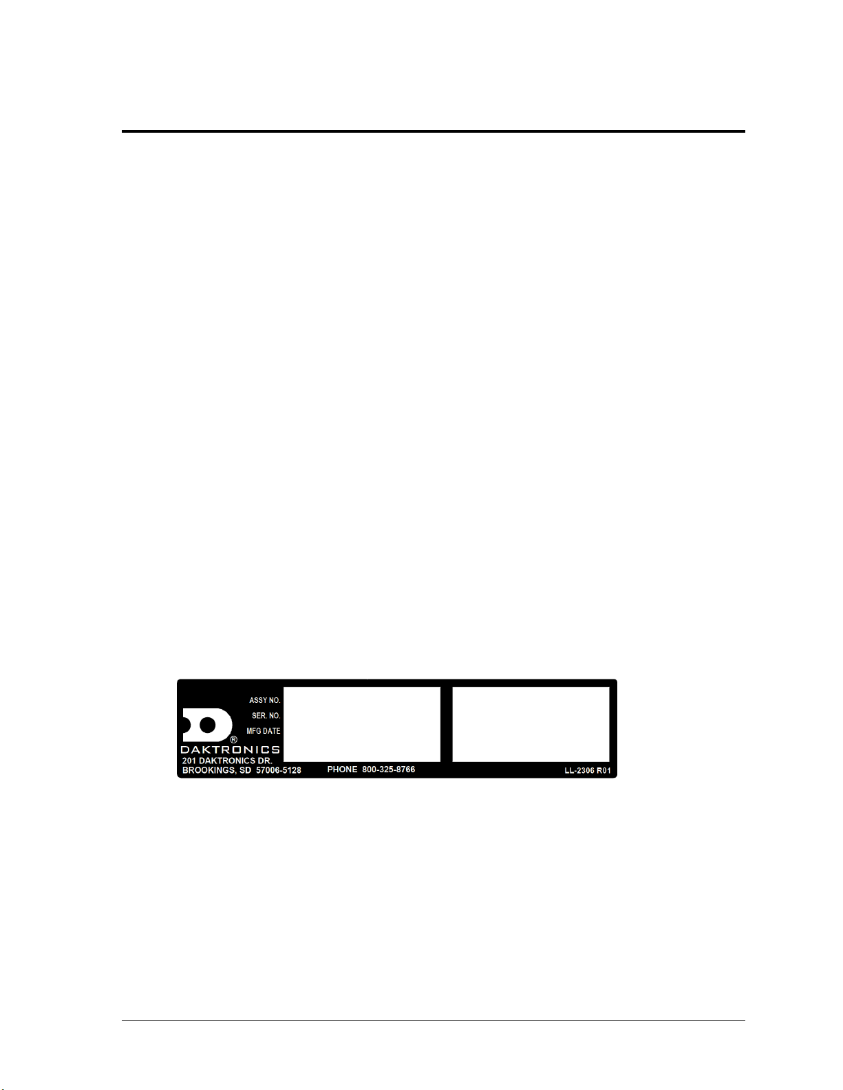
Figure 1: Specifications Label
Section 1: Introduction
This manual explains the installation and maintenance of Daktronics LED End-of-Period (EOP)
Basketball Lighting systems, which includes the BB-2134 backboard kit and scorer’s table kit. For
additional information regarding the safety, installation, operation, or service of these displays, refer to
the telephone numbers listed in Section 4.7. This manual is not specific to a particular installation.
Project-specific information takes precedence over any other general information found in this manual.
IMPORTANT SAFEGUARDS:
Please read and understand all instructions before beginning the installation process.
Do not drop control equipment or allow it to get wet.
Do not disassemble control equipment or electronic controls of the display; failure to
follow this safeguard will make the warranty null and void.
Disconnect display power when not in use or when servicing.
Disconnect display power before servicing power supplies to avoid electrical shock.
Power supplies run on high voltage and may cause physical injury if touched while
powered.
Do not modify the scoreboard structure or attach any panels or coverings to the
scoreboard without the express written consent of Daktronics, Inc.
1.1 Specifications Label
Power specifications as well as serial and model number information can be found on an ID
label on the device, similar to the one shown in Figure 1.
Please have the assembly number, model number, and the date manufactured on hand when
calling Daktronics customer service to ensure the request is serviced as quickly as possible.
Knowing the facility name and/or job number will also be helpful.
Introduction
Page 8
1.2 Resources
Main Component Labels
Part Type
Part Number
Individual circuit board
0P-XXXX-XXXX
Assembly; a collection of circuit boards
0A-XXXX-XXXX
Wire or cable
W-XXXX
Fuse
F-XXXX
Transformer
T-XXXX
Metal part
M-XXX
Fabricated metal assembly
0S-XXXXXX
Specially ordered part
PR-XXXXX-X
Accessory Labels
Component
Label
Termination block for power
or signal cable
TBXX
Grounding point
EXX
Power or signal jack
JXX
Power or signal plug for the
opposite jack
PXX
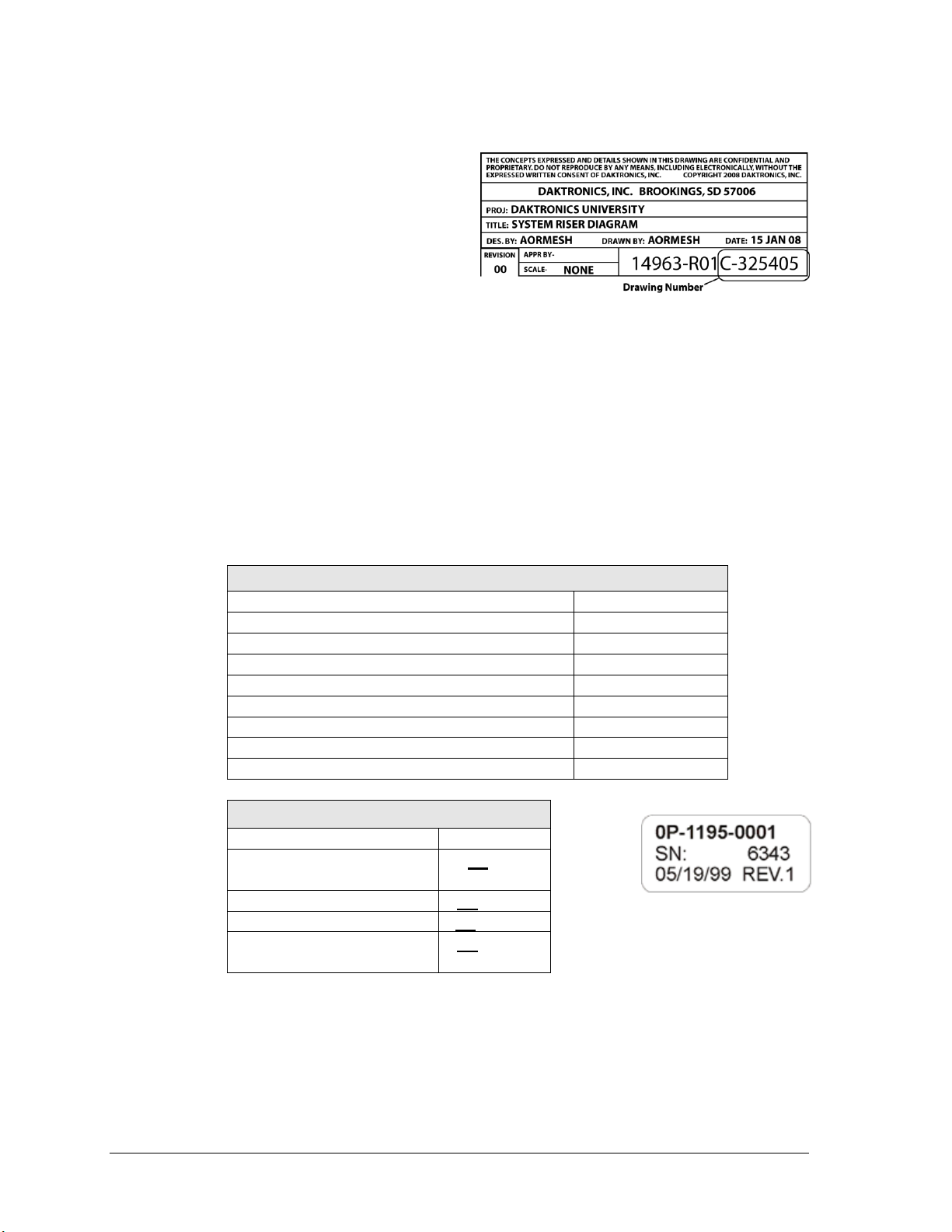
Figure 2: Daktronics Drawing Label
Figure 3: Typical Label
Figure 2 illustrates a Daktronics drawing
label. The drawing number is located in the
lower-right corner of a drawing. This
manual refers to drawings by listing the
last set of digits and the letter preceding
them. In the example, the drawing would
be referred to as Drawing C-325405.
Reference Drawing:
System Riser Diagram ............................................................................Drawing C-325405
Daktronics identifies manuals by the DD or ED number located on the cover page of each
manual. For example, this manual would be referred to as ED-13652.
1.3 Daktronics Nomenclature
Most components within this display carry a white label that lists the part number of the unit.
If a component is not found in the Replacement Parts List in Section 4.5, use the label to order
a replacement. Figure 3 illustrates a typical label. The part number is in bold.
Following the Replacement Parts List is the Daktronics Exchange Policy and the Repair &
Return Program. Refer to these instructions if replacing or repairing any display component.
2 Introduction
Page 9

Section 2: Backboard Lighting Kit
2.1 Mechanical Installation
Reference Drawings:
Mechanical/Electrical Specs- Light Strip Controller ............................... Drawing A-176435
NBA Light Strips Back board Installation ............................................... Drawing B-580363
NBA 24 Second Violation Light Strip Installation .................................... Drawing A-892536
Install the backboard LED lighting by following these steps:
1. Lay out all the LED strips on the floor and arrange them in the shape of the
backboard. The longest strip should be to the top, and the power cord should come
out the bottom left light strip, as viewed from the front of the display.
2. The top LED strip will be attached to the backboard first, and the rest of the light
strips will hang down off the ends of the top light strip.
a. Attach the six mounting clips to the top LED strip using the provided #6 screws.
b. Secure the LED strip to the backboard tubing with the provided #10 self-drilling
screws. The LEDs should be flush with the glass. Refer to “Detail: A” on
Drawing B-580363 in Appendix A.
3. Mount the side and bottom LED strips into place in a similar fashion to the top strip.
4. If an LED strip controller box is used to run the backboard light strips, attach
mounting brackets to the controller and attach it to the backstop. Refer to Drawing
A-176435 in Appendix A for mounting details.
Note: Drawing A-892536 in Appendix A details the installation of the 24-second shot clock
violation backboard light strip, which requires an extended mounting clip for the top strips.
2.2 Electrical Installation
Reference Drawings:
Mechanical/Electrical Specs- Light Strip Controller ............................... Drawing A-176435
System Riser; EOP LED Lights w/ 4-Sided S.C. .................................... Drawing B-176737
The LED backboard lighting will receive power/signal from one of three places:
1. A shot clock equipped with an LED lighting XLR jack
2. An LED light strip controller box
3. A transparent shot clock controller box with an LED lighting XLR jack
Use the 30' (9.1 m) jumper cable provided with the kit to connect the XLR plug protruding
from the bottom of the LED light strip to one of the above sources. If the jumper cable is too
long, cut it and reattach the XLR plug to the end.
Drawing B-176737 in Appendix A illustrates a typical setup using both controller and shot
clocks for light strip power. The mating XLR jacks on the light strip controller are shown in
the rear views on Drawing A-176435. For shot clock XLR jack locations, refer to the specific
component location drawings included in the shot clock’s manual.
Backboard Lighting Kit 3
Page 10

Page 11

Section 3: Scorer’s Table Lighting Kit
3.1 Mechanical Installation
Reference Drawings:
Mechanical/Electrical Specs- Light Strip Controller ............................... Drawing A-176435
Mechanical Spec, 5' Sectional Light Strips ............................................ Drawing A-197074
The LED light strip comes with a number of 1" (25 mm) adhesive-backed, hook-and-loop
fastener pieces. Each of these pieces is to be applied to the back or bottom of the LED light
strip and connected to a mating strip that is attached to the scorer's table frame. Two
extended mounting clips come attached to the light strip; these may be removed if desired.
Drawing A-197074 in Appendix A illustrates several variations for the attachment.
A controller box required to run the light strip can either be set on the table (resting on rubber
pads) or mounted under the table using mounting brackets provided with the unit. Drawing
A-176435 in Appendix A shows the attachment of a control box with the mounting brackets.
3.2 Electrical Installation
Reference Drawings:
Installation Details: LED Light Strip Controller ....................................... Drawing B-176174
Mechanical/Electrical Specs- Light Strip Controller ............................... Drawing A-176435
System Riser; EOP LED Lights w/ 4-Sided S.C. .................................... Drawing B-176737
Mechanical Spec, 5' Sectional Light Strips ............................................ Drawing A-197074
The LED light strip is equipped with a 6'-6" (1.98 m) power cord with an XLR plug. This can
be plugged directly into the controller, or the provided 30' (9.1 m) jumper cable can be used
to reach the controller location. As scorer’s table light strips are often installed in pairs, the
controller includes two power output jacks (J21 and J22). The light strip controller is equipped
with a three-prong plug and requires a 120 VAC outlet. Refer to Drawing A-176435 in
Appendix A for details on the light strip controller power and signal connections.
Up to five separate 5' (1.52 m) light strips may be connected from single output on the
controller. Drawing A-197074 in Appendix A illustrates the connections between light strip
sections. The light strip sections may be disconnected and removed from the scorer’s tables
for storage.
Drawing B-176174 in Appendix A provides power and signal installation details for various
light strip controller systems, and Drawing B-176737 provides an overall view of electrical
connections for a typical lighting system.
Electrical Installation 5
Page 12

Page 13

Symptom/Condition
Solution/Items to Check
Display doesn't light at all.
Check all cable connections:
Power to the light strip controller (or shot clock)
Signal to the light strip controller (or shot clock) from the
scoreboard controller
Signal from the light strip controller (or shot clock) to the light
strip itself
When using an All Sport 5000 Series controller, ensure there is
an address plug on the light strip control driver set to address 1
(refer to Section 4.3).
Note: Setups using an All Sport 4000 or ProSport 6000 controller
do not require this address plug.
Replace controller driver (refer to Section 4.3).
Light strip comes on at
wrong time.
Make sure gray wire from J6 is connected to appropriate position
on terminal block inside controller. Refer to Drawing A-176435 in
Appendix A.
Individual LED, or section of
LEDs, is not working.
Swap section of light strip with one known to work correctly to
verify it is defective.
Replace defective portion of light strip.
Section 4: Maintenance & Troubleshooting
IMPORTANT NOTES:
1. Disconnect power before doing any repair work on the display.
2. Allow only qualified service personnel access to internal display electronics.
3. Disconnect power when not using the display.
4.1 Troubleshooting Table
The table below lists potential problems with the lighting system and indicates possible
causes and corrective actions. This list does not include every symptom that may be
encountered, but it does present several of the most common situations that may occur.
If a problem occurs that is not listed or that cannot be resolved using the solutions in the
following table, contact Daktronics using the information provided in Section 4.7.
For additional troubleshooting of a shot clock, scoreboard controller, or other system
component, refer to the product manuals located online at www.daktronics.com/manuals.
Maintenance & Troubleshooting 7
Page 14

4.2 Component Location & Access
LED end-of-period lighting system components should be located at the scorer's table and at
each backboard. Light strips are mounted directly to each backboard with mounting clips,
and to the scorer's table with hook-and-loop fasteners. The individual parts of the light strips
are directly accessible.
The light strip controller will typically be located on or under the scorer's table or, for
backboard lighting without a shot clock, on the backboard backstop. Power and signal
connections are external, and if necessary, internal components can be accessed by removing
the device's cover.
4.3 LED Drivers
Reference Drawings:
4 Column LED Driver II Specifications.................................................... Drawing A-123783
Mechanical/Electrical Specs- Light Strip Controller ................................ Drawing A-176435
Daktronics LED light strip controllers use 4-column LED drivers to perform the task of
switching LEDs on and off. Refer to Drawing A-123783 in Appendix A for detailed driver
pin out/switch specifications.
Note: The control box used to interface with non-Daktronics equipment does not include
an LED driver.
Replacing a Driver
1. Open the LED light strip controller enclosure by removing the two screws on the bottom
and lifting off the top. Refer to Drawing A-176435 in Appendix A.
2. Disconnect all connectors from the driver by squeezing together the locking tabs and
pulling the connectors free.
Note: It may be helpful to label the cables to know which cable goes to which connector
when reattaching the driver.
3. Remove the four #6 screws securing the driver to the inside of the controller enclosure.
4. Carefully lift the driver from the display and place it on a clean, flat surface.
5. Position a new driver inside the controller enclosure and tighten the screws.
6. Reconnect all power/signal connectors.
Note: The connectors are keyed and will attach in one way only. Do not attempt to force
the connections.
7. Ensure the driver is set to the correct address (refer to Setting the Driver Address).
8. Close and secure the controller enclosure, then power up and test the light strips to see if
changing the driver has resolved the problem.
8 Maintenance & Troubleshooting
Page 15

Description
Daktronics Part #
Address 1 plug
0A-1150-0122
LED driver, 4-column
0P-1150-0130
Cable; 3-pin XLR male to female, 30'
0A-1230-0090
Light strip, full mod, amber (24 sec violation)
0A-1230-0135
Light strip, half mod, amber (24 sec violation)
0A-1230-0136
14.375" Red LED light strip (scorer’s table)
0P-1230-0137
Light strip, full mod, red (standard backboard)
0A-1230-0141
Light strip, half mod, red (standard backboard)
0A-1230-0142
48" light strip ( scorer’s table clock stopped indicator)
0A-1237-1313
Transformer, 120P/16S, 6.3 A
T-1066
Figure 4: Address Jack J19
Setting the Driver Address (All Sport 5000 Only)
Since the same LED drivers can be used for many scoreboard
models, each driver must be set to receive the correct signal
input, or address, for the model being used. This address is
set with jumper wires in a 12-pin plug which mates with jack
J19 on the driver (Figure 4).
It may be possible to reuse the same address plug from the
driver that was replaced. If not, be sure to contact Daktronics
to order an address 1 plug (part # 0A-1150-0122).
4.4 Schematics
Reference Drawings:
Schem: LED Light Strip Controller ......................................................... Drawing A-176075
For advanced troubleshooting and repair, it may be necessary to consult a schematic
drawing. Drawing A-176075 in Appendix A represents the schematic diagrams for the LED
light strip controller. The schematic includes power and signal inputs and all internal wiring
for the lighting system.
4.5 Replacement Parts List
Refer to the following table for Daktronics scoreboard replacement parts.
4.6 Routine/Preventative Maintenance
Perform an annual visual inspection of each display and check the following:
Check and tighten fasteners or replace them as required.
Check the electrical components for proper connection and any signs of corrosion.
Maintenance & Troubleshooting 9
Page 16

Market Description
Customer Service Number
Schools (including community/junior colleges), religious
organizations, municipal clubs and community centers
877-605-1115
Universities and professional sporting events, live events
for auditoriums and arenas
866-343-6018
4.7 Daktronics Exchange and Repair & Return Programs
Exchange Program
The Daktronics Exchange Program is a service for quickly replacing key components in need
of repair. If a component fails, Daktronics sends a replacement part to the customer who, in
turn, returns the failed component to Daktronics. This decreases equipment downtime.
Customers who follow the program guidelines explained below will receive this service.
Before Contacting Daktronics
Identify these important numbers:
Display Serial Number: _________________________________________________________
Display Model Number: ________________________________________________________
Job/Contract Number:__________________________________________________________
Date Installed: _________________________________________________________________
Daktronics Customer ID Number: ________________________________________________
To participate in the Exchange Program, follow these steps.
1. Call Daktronics Customer Service.
2. When the new exchange part is received, mail the old part to Daktronics.
If the replacement part fixes the problem, send in the problem part being replaced.
a. Package the old part in the same shipping materials in which the replacement
part arrived.
b. Fill out and attach the enclosed UPS shipping document.
c. Ship the part to Daktronics.
3. The defective or unused parts must be returned to Daktronics within 5 weeks of
initial order shipment.
If any part is not returned within five (5) weeks, a non-refundable invoice will be
presented to the customer for the costs of replenishing the exchange parts inventory
with a new part.
Daktronics reserves the right to refuse parts that have been damaged due to acts of
nature or causes other than normal wear and tear.
10 Maintenance & Troubleshooting
Page 17

Repair & Return Program
For items not subject to exchange, Daktronics offers a Repair & Return Program. To send a
part for repair, follow these steps:
1. Call or fax Daktronics Customer Service:
Refer to the appropriate market number in the chart listed on the previous page.
Fax: 605-697-4444
2. Receive a case number before shipping.
This expedites repair of the part.
3. Package and pad the item carefully to prevent damage during shipment.
Electronic components, such as printed circuit boards, should be placed in an
antistatic bag before boxing. Daktronics does not recommend using packing ‘peanuts’
when shipping.
4. Enclose:
name
address
phone number
the case number
a clear description of symptoms
Shipping Address
Daktronics Customer Service
[Case #]
201 Daktronics Drive, Dock E
Brookings, SD 57006
Daktronics Warranty and Limitation of Liability
The Daktronics Warranty and Limitation of Liability is located in Appendix B. The Warranty
is independent of Extended Service agreements and is the authority in matters of service,
repair, and display operation.
Maintenance & Troubleshooting 11
Page 18

Page 19

Appendix A: Reference Drawings
Drawing Title Drawing Number
4 Column LED Driver II; Specifications ..................................................................................... A-123783
Mechanical Spec, Backboard LED Lighting .............................................................................. A-175504
Schem: LED Light Strip Controller ............................................................................................ A-176075
Installation Details: LED Light Strip Controller .......................................................................... B-176174
Mechanical/Electrical Specs- Light Strip Controller .................................................................. A-176435
System Riser; EOP LED Lights w/ 4-Sided S.C. ...................................................................... B-176737
Mechanical Spec, 5' Sectional Light Strips ............................................................................... A-197074
Connection Details, NBA, LED Light Strip Controller................................................................ A-497258
NBA Light Strips Back Board Installation .................................................................................. B-580363
NBA 24 Second Violation Light Strip Installation ...................................................................... A-892536
Reference Drawings 13
Page 20

Page 21

Page 22

Page 23

Page 24

Page 25

12345
TB11
SHOT CLK
HORNHORN
GAME CLKGAME
CLK = 0= STOP
GAME CLK
NOT USED
NOT USED
GAME CLK
= STOP CLK = 0
GAME GAME CLK
HORN HORN
SHOT CLK
TB11
5 4 3
2
1
Page 26

Page 27

Page 28

Page 29

Page 30

Page 31

Appendix B: Daktronics Warranty and Limitation
of Liability
Daktronics Warranty and Limitation of Liability 15
Page 32

Page 33

DAKTRONICS WARRANTY & LIMITATION OF LIABILITY
This Warranty and Limitation of Liability (the “Warranty”) sets forth the warranty provided by Daktronics with respect to the Equipment. By accepting delivery of the
Equipment, Purchaser agrees to be bound by and accept these terms and conditions. Unless otherwise defined herein, all terms within the Warranty shall have the
same meaning and definition as provided elsewhere in the Agreement.
DAKTRONICS WILL ONLY BE OBLIGATED TO HONOR THE WARRANTY SET FORTH IN THESE TERMS AND CONDITIONS UPON RECEIPT OF FULL PAYMENT FOR THE
EQUIPMENT.
1. Warranty Coverage
2. Exclusion from Warranty Coverage
A. Daktronics warrants to the original end-user that the Equipment will be free from Defects (as defined below) in materials and
workmanship for a period of one (1) year (the “Warranty Period”). The Warranty Period shall commence on the earlier of: (i) four weeks from the date
that the Equipment leaves Daktronics’ facility; or (ii) Substantial Completion as defined herein. The Warranty Period shall expire on the first anniversary
of the commencement date.
“Substantial Completion” means the operational availability of the Equipment to the Purchaser in accordance with the Equipment’s specifications,
without regard to punch-list items, or other non-substantial items which do not affect the operation of the Equipment.
B. Daktronics’ obligation under this Warranty is limited to, at Daktronics’ option, replacing or repairing, any Equipment or part thereof that is found by
Daktronics not to conform to the Equipment’s specifications. Unless otherwise directed by Daktronics, any defective part or component shall be
returned to Daktronics for repair or replacement. This Warranty does not include on-site labor charges to remove or install these components.
Daktronics may, at its option, provide on-site warranty service. Daktronics shall have a reasonable period of time to make such replacements or repairs
and all labor associated therewith shall be performed during regular working hours. Regular working hours are Monday through Friday between 8:00
a.m. and 5:00 p.m. at the location where labor is performed, excluding any holidays observed by either Purchaser or Daktronics.
C. Daktronics shall pay ground transportation charges for the return of any defective component of the Equipment. All such items shall be shipped by
Purchaser DDP Daktronics; designated facility. If returned Equipment is repaired or replaced under the terms of this warranty, Daktronics will prepay
ground transportation charges back to Purchaser and shall ship such items DDP Purchaser’s designated facility; otherwise, Purchaser shall pay
transportation charges to return the Equipment back to the Purchaser and such Equipment shall be shipped Ex Works Daktronics designated facility. All
returns must be pre-approved by Daktronics before shipment. Daktronics shall not be obligated to pay freight for any unapproved return. Purchaser
shall pay any upgraded or expedited transportation charges.
D. Any replacement parts or Equipment will be new or serviceably used, comparable in function and performance to the original part or Equipment, and
warranted for the remainder of the Warranty Period. Purchasing additional parts or Equipment from the Seller does not extend the Warranty Period.
E. Defects shall be defined as follows. With regard to the Equipment (excepting LEDs), a “Defect” shall refer to a material variance from the design
specifications that prohibit the Equipment from operating for its intended use. With respect to LEDs, “Defects” are defined as LED pixels that cease to
emit light. The limited warranty provided by Daktronics does not impose any duty or liability upon Daktronics for partial LED pixel degradation nor does
the limited warranty provide for the replacement or installation of communication methods including but not limited to, wire, fiber optic cable, conduit,
trenching, or for the purpose of overcoming local site interference radio equipment substitutions.
EXCEPT AS OTHERWISE EXPRESSLY SET FORTH IN THIS WARRANTY, TO THE MAXIMUM EXTENT PERMITTED BY APPLICABLE LAW, DAKTRONICS DISCLAIMS
ANY AND ALL OTHER PROMISES, REPRESENTATIONS AND WARRANTIES APPLICABLE TO THE EQUIPMENT AND REPLACES ALL OTHER WARRANTIES OR
CONDITIONS, EXPRESS OR IMPLIED, INCLUDING, BUT NOT LIMITED TO ANY IMPLIED WARRANTIES OR CONDITIONS OF MERCHANTABILITY, FITNESS FOR A
PARTICULAR PURPOSE, ACCURACTY OR QUALITY OF DATA. NO ORAL OR WRITTEN INFORMATION, OR ADVICE GIVEN BY THE COMPANY, ITS AGENTS OR
EMPLOYEES, SHALL CREATE A WARRANTY OR IN ANY WAY INCREASE THE SCOPE OF THIS LIMITED WARRANTY.
THIS LIMITED WARRANTY IS NOT TRANSFERABLE.
The limited warranty provided by Daktronics does not impose any duty or liability upon Daktronics for:
A. Any damage occurring, at any time, during shipment of Equipment unless otherwise provided for in the Agreement. When returning Equipment to
Daktronics for repair or replacement, Purchaser assumes all risk of loss or damage, and agrees to use any shipping containers that might be provided by
Daktronics and to ship the Equipment in the manner prescribed by Daktronics;
B. Any damage caused by the improper installation, adjustment, repair or service of the Equipment by anyone other than personnel of Daktronics or its
authorized repair agents;
C. Damage caused by the failure to provide a continuously suitable environment, including, but not limited to: (i) neglect or misuse, (ii) a failure or
sudden surge of electrical power, (iii) improper air conditioning, humidity control, or other environmental conditions outside of the Equipment’s
technical specifications such as extreme temperatures, corrosives and metallic pollutants, or (iv) any other cause other than ordinary use;
D. Damage caused by fire, flood, earthquake, water, wind, lightning or other natural disaster, strike, inability to obtain materials or utilities, war,
terrorism, civil disturbance or any other cause beyond Daktronics’ reasonable control;
Copyright © Daktronics, Inc. SL-02374 Rev 12 27Jun14 Page 1 of 2
Page 34

DAKTRONICS WARRANTY & LIMITATION OF LIABILITY
E. Failure to adjust, repair or replace any item of Equipment if it would be impractical for Daktronics personnel to do so because of connection of the
Equipment by mechanical or electrical means to another device not supplied by Daktronics, or the existence of general environmental conditions at the
site that pose a danger to Daktronics personnel;
3. Limitation of Liability
4. Assignment of Rights
5. Governing Law
6. Availability of Extended Service Agreement
F. Any statements made about the product by any salesperson, dealer, distributor or agent, unless such statements are in a written document signed by
an officer of Daktronics. Such statements as are not included in a signed writing do not constitute warranties, shall not be relied upon by Purchaser and
are not part of the contract of sale;
G. Any damage arising from the use of Daktronics products in any application other than the commercial and industrial applications for which they are
intended, unless, upon request, such use is specifically approved in writing by Daktronics;
H. Any performance of preventive maintenance;
J. Third-party systems and other ancillary equipment including without limitation front-end video control systems, audio systems, video processors and
players, HVAC equipment, batteries and LCD screens;
K. Incorporation of accessories, attachments, software or other devices not furnished by Daktronics; or
L. Paint or refinishing the Equipment or furnishing material for this purpose.
Daktronics shall be under no obligation to furnish continued service under this Warranty if alterations are made to the Equipment without the prior
written approval of Daktronics.
It is specifically agreed that the price of the Equipment is based upon the following limitation of liability. In no event shall Daktronics (including its
subsidiaries, affiliates, officers, directors, employees, or agents) be liable for any special, consequential, incidental or exemplary damages arising out of or
in any way connected with the Equipment or otherwise, including but not limited to damages for lost profits, cost of substitute or replacement
equipment, down time, lost data, injury to property or any damages or sums paid by Purchaser to third parties, even if Daktronics has been advised of
the possibility of such damages. The foregoing limitation of liability shall apply whether any claim is based upon principles of contract, tort or statutory
duty, principles of indemnity or contribution, or otherwise.
In no event shall Daktronics be liable to Purchaser or any other party for loss, damage, or injury of any kind or nature arising out of or in connection with
this Warranty in excess of the purchase price of the Equipment actually delivered to and paid for by the Purchaser. The Purchaser’s remedy in any
dispute under this Warranty shall be ultimately limited to the Purchase Price of the Equipment to the extent the Purchase Price has been paid.
The Warranty contained herein extends only to the original end-user (which may be the Purchaser) of the Equipment and no attempt to extend the
Warranty to any subsequent user-transferee of the Equipment shall be valid or enforceable without the express written consent of Daktronics.
The rights and obligations of the parties under this warranty shall not be governed by the provisions of the United Nations Convention on Contracts for
the International Sales of Goods of 1980. Both parties consent to the application of the laws of the State of South Dakota to govern, interpret, and
enforce all of Purchaser and Daktronics rights, duties, and obligations arising from, or relating in any manner to, the subject matter of this Warranty,
without regard to conflict of law principles.
For Purchaser’s protection, in addition to that afforded by the warranties set forth herein, Purchaser may purchase extended warranty services to cover
the Equipment. The Extended Service Agreement, available from Daktronics, provides for electronic parts repair and/or on-site labor for an extended
period from the date of expiration of this warranty. Alternatively, an Extended Service Agreement may be purchased in conjunction with this warranty
for extended additional services. For further information, contact Daktronics Customer Service at 1-800-DAKTRONics (1-800-325-8766).
Copyright © Daktronics, Inc. SL-02374 Rev 12 27Jun14 Page 2 of 2
 Loading...