

Page 1

DakTicker®
KE-1010 Series
GEN II
Installation/Operation Manual
ED-15353 Rev 1 27 April 2007
Website: www.daktronics.com
Tel 866-343-3122 Fax 605-697-4444
nd
331 32
Ave PO Box 5128 Brookings SD 57006
Page 2
ED-15353
Product 1182
Rev 1 – 27 April 2007
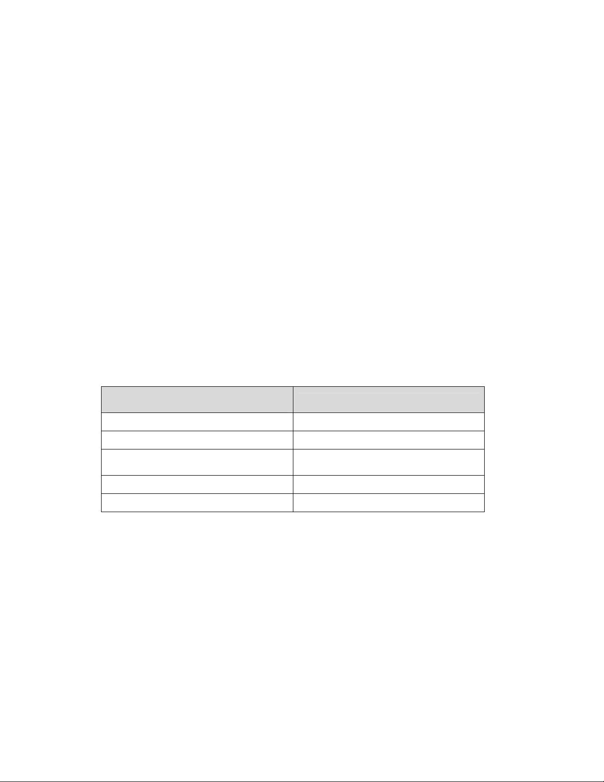
Fill in the chart with specific information about this display so the details are readily
available when calling for service or replacement parts.
Information needed for technicians
and/or Customer Service
Location address of the display:
Model number of this display:
Version of software being used:
(Consult software for this information.)
Method of communication:
Network address:
Fill in the blanks
KE-1010
RS-422 or Ethernet
Copyright © 2003-2007
All rights reserved. While every precaution has been taken in the preparation of this manual,
the publisher assumes no responsibility for errors or omissions. No part of this book covered
by the copyrights hereon may be reproduced or copied in any form or by any means –
graphic, electronic, or mechanical, including photocopying, taping, or information storage and
retrieval systems – without written permission of the publisher.
DakTicker
®
and DataStreamer™ are trademarks of Daktronics, Inc.
Page 3

Table of Contents
Section 1: Introduction................................................................................................................. 1
1.1 Display Overview ...................................................................................................................1
1.2 Drawing References................................................................................................................2
1.3 Safety Precautions...................................................................................................................2
Section 2: Mechanical Installation..............................................................................................3
2.1 Support Structure Design ......................................................................................................3
2.2 Display Mounting...................................................................................................................4
Ceiling Mount ..................................................................................................................4
Wall Mount.......................................................................................................................4
Mounting Multi-section Tickers ....................................................................................5
Section 3: Power Installation.......................................................................................................7
3.1 Power Requirements ..............................................................................................................7
3.2 Power Cord - Grounding.......................................................................................................8
Section 4: Signal Installation.......................................................................................................9
4.1 Network Options ....................................................................................................................9
RS-422 Connections .........................................................................................................9
Ethernet Connections ....................................................................................................11
4.2 Section to Section Connections............................................................................................12
4.3 Master to Master Connections ............................................................................................12
4.4 Installation Checklist............................................................................................................13
4.5 Boot Up Sequence .................................................................................................................13
Section 5: Maintenance & Troubleshooting.............................................................................15
5.1 Display Maintenance............................................................................................................15
Controller Diagnostic LEDs..........................................................................................15
Visual Structural Inspection.........................................................................................16
5.2 Troubleshooting ....................................................................................................................16
5.3 Definitions..............................................................................................................................17
Section 6: Parts Replacement...................................................................................................19
6.1 Replacement Parts List.........................................................................................................19
6.2 Removing the Face Panel.....................................................................................................21
6.3 Instructions for Replacing Parts..........................................................................................22
LED Module Replacement............................................................................................22
Power Supply Replacement .........................................................................................23
Shift Card Replacement ................................................................................................23
Controller Replacement ................................................................................................24
Controller Address ........................................................................................................25
Table of Contents i
Page 4

Daktronics Exchange and Repair & Return Program ......................................................25
6.4
Exchange Program.........................................................................................................25
Repair & Return Program.............................................................................................26
Appendix A: Reference Drawings .................................................................................................27
Appendix B: Signal Converter .......................................................................................................29
Appendix C: Ethernet Configuration.............................................................................................35
ii
Table of Contents
Page 5

List of Figures
Figure 1: KE-1010 Display......................................................................................................................1
Figure 2: Basic Display Setup.................................................................................................................1
Figure 3: Front of 16 x 40 Module...........................................................................................................2
Figure 4: Drawing Label..........................................................................................................................2
Figure 5: Mounting Options.....................................................................................................................3
Figure 6: Ceiling Mount...........................................................................................................................4
Figure 7: Wall Mount...............................................................................................................................4
Figure 8: Master-Echo Installation Detail................................................................................................5
Figure 9: 16 and 24 High DakTickers Power Connection ......................................................................7
Figure 10: 16 High Twin DakTicker Power Connection..........................................................................7
Figure 11: Power Cord Connection ........................................................................................................8
Figure 12: RS-422 Signal Layout............................................................................................................9
Figure 13: Ethernet Signal Layout........................................................................................................11
Figure 14: Shift Board...........................................................................................................................12
Figure 15: Master to Echo Connection.................................................................................................12
Figure 16: Master to Master RS-422 Connection.................................................................................13
Figure 17: Controller with Diagnostic LEDs..........................................................................................15
Figure 18: Typical Label........................................................................................................................19
Figure 19: Removing the Face Panel...................................................................................................21
Figure 20: Detaching a Module.............................................................................................................22
Figure 21: Removing a Module.............................................................................................................22
Figure 22: Power Supply Wiring...........................................................................................................23
Figure 23: Shift Board...........................................................................................................................23
Figure 24: Display Controller ................................................................................................................24
Figure 25: RS-232 to RS-422 Signal Converter...................................................................................30
Figure 26: Flipped Cable (Reversed)....................................................................................................31
Figure 27: Straight Cable......................................................................................................................31
Figure 28: Network Cable Tester..........................................................................................................31
Figure 29: Signal Converter Enclosure.................................................................................................33
List of Figures iii
Page 6

Page 7
Section 1: Introduction
The Daktronics DakTicker™ KE-1010 displays are designed and manufactured for performance,
reliability, easy maintenance, and long life. To ensure the optimal performance of this display, the
manual explains the installation and maintenance of the KE-1010 displays. Sections 2, 3, and 4
provide mechanical, power, and signal installation instructions. Later sections include diagnostic and
parts replacement information, along with the instructions for obtaining parts from Daktronics
Customer Service. Definitions of terms are provided in Section 5.3. A DakTicker display is shown in
Figure 1.
Figure 1: KE-1010 Display
1.1 Display Overview
The DakTicker model number is described as follows:
KE-1010
HH
CCC
7.62
RG
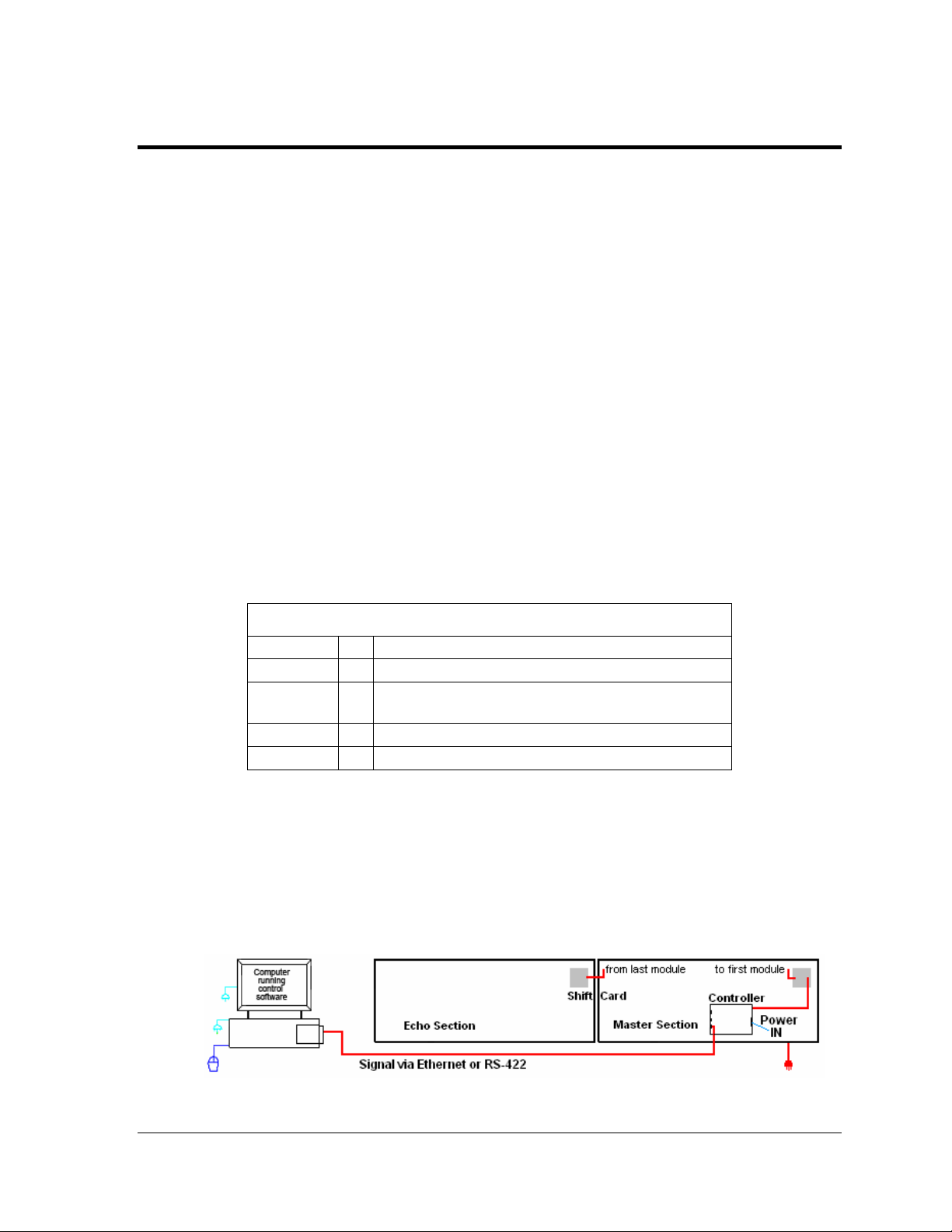
The displays are offered as single-face (one-sided) units which may consist of a number of
separate sections. Two types of display sections are used, one called the “master” and the
other an “echo.” Master sections contain the controller board which receives information
from the computer. Echo displays do not contain a controller board and require a master
display to operate. Displays show information from a third party source, such as a wire
service, ticker input, or Internet service, and scroll these messages from right to left on the
display. A generic KE-1010 setup is illustrated in Figure 2.
KE-1010-HHxCCC-7.62-RG
= Indoor DakTicker display
= Number of pixels high (16 or 24)
Number of columns wide
=
(120, 160, 200, 240, 280, 320, 360, 400)
= Pixel spacing in millimeters
= Tri-color (Red, Green, and Amber)
Figure 2: Basic Display Setup
Introduction 1
Page 8
A module is the building block of the DakTicker display.
By placing modules side-by-side, a display of any length
can be designed and built. Individual modules can be
easily removed from the display, if required
modules consist of an array of LED (light emitting diode)
pixels that are available in several matrix sizes. The
height options include 16-pixels high and 24-pixels high
as well as a twin ticker with two separate sections of 16
pixels high. Text can be configured into one large font or
two to three lines of smaller fonts, as shown in Figure 1.
Tickers are available in tri-color (red, green and amber) characters.
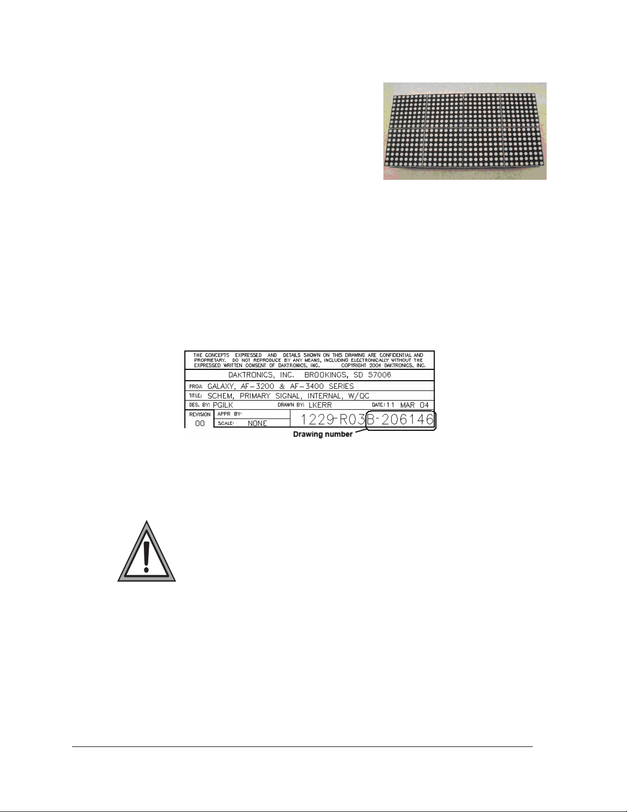
1.2 Drawing References
Drawings may be referenced at the beginning of a section and also within the text. The
reference number consists of the last set of digits and the letter preceding them on the
drawing label (Figure 4). The drawing number is located in the lower-right corner of the
drawing. In the example below, the drawing would be referred to as Drawing B-206146.
Reference drawings are inserted or listed in Appendix A.
. KE-1010
Figure 3: Front of 16 x 40 Module
Figure 4: Drawing Label
1.3 Safety Precautions
• Read and understand these instructions before installing.
• Be sure that the display is properly grounded.
• Disconnect power when servicing the display.
• Do not modify the display structure or attach any panels or coverings to
the display without the written consent of Daktronics.
2
Introduction
Page 9
Section 2: Mechanical Installation
Mechanical installation includes both support structure design and mounting methods. Two
mounting methods are explained in this section, wall mount and ceiling mount.
• Daktronics engineering staff must approve any changes made to the displays. If any
modifications are made, detailed drawings of the changes must be submitted to
Daktronics for evaluation and approval or the warranty may be void.
• Daktronics is not responsible for the installations or the structural integrity of support
structures installed by others.
Reference Drawings:
Shop Drawings ............................................................................................Listed in Appendix A
Mounting Drawing, Ceiling, KE-1010 ............................................................. Drawing A-118572
Shop Dwg, Horiz. Wall Mount, Gen II KE-1010 ............................................. Drawing A-234483
2.1 Support Structure Design
DakTicker KE-1010 displays are generally mounted on the wall or from the ceiling. Support
structure design depends on mounting methods, display size, and weight. (Figure 5). The
structure design is critical and should be done only by a qualified individual. It is the
customer’s responsibility to ensure that the structure and the connectors are adequate. Refer
to the Shop Drawings listed in Appendix A for dimensions and mounting clip locations.
Attaching or hanging anything from the display will render the warranty null and void.
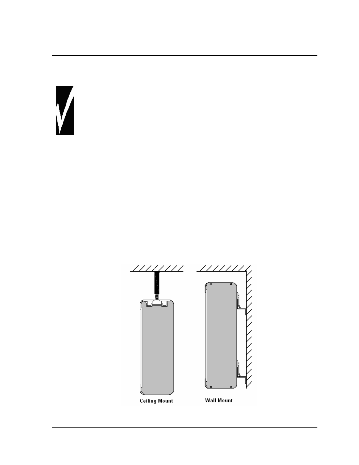
Figure 5: Mounting Options
Mechanical Installation 3
Page 10
2.2 Display Mounting
• It is the customer’s responsibility to ensure that the installation will meet local
standards.
• The mounting hardware must be capable of supporting all components to be
mounted.
Daktronics recommends either a wall mount or hanging mount method (Figure 5).
Remember to have all mounted displays inspected by a qualified structural engineer.
Ceiling Mount
Splice bars, provided by Daktronics, have 3/8"-16 UNC holes that can be used
to secure the ticker displays from a ceiling or other overhead structure. Use the
middle hole only when using the splice bars for mounting. Daktronics does
not provide the ceiling mounting supports. To hang a ticker, refer to Drawing
A-118572 and the following instructions:
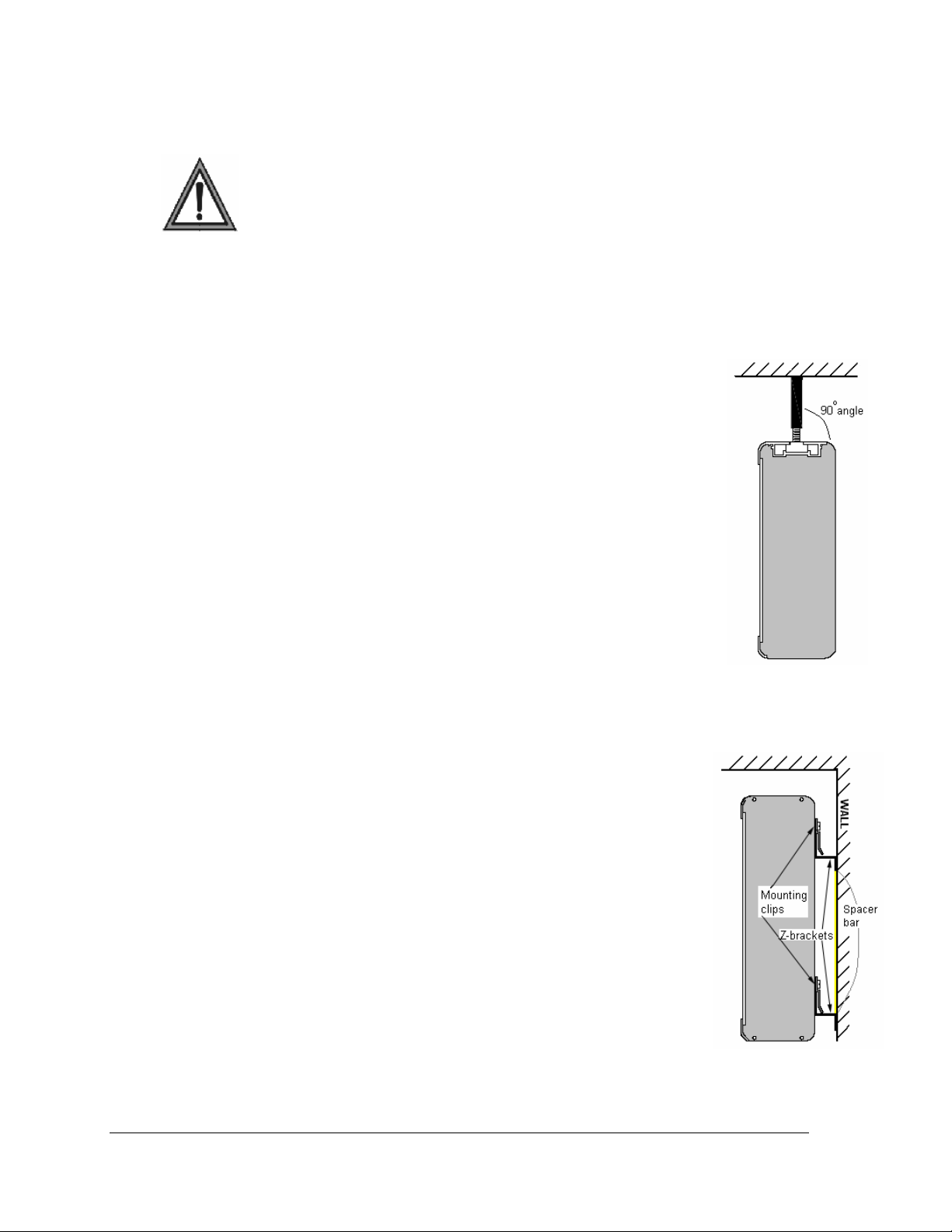
1. Determine and mark the locations where the ceiling mounting
supports will attach to the overhead structure. The supports, when
installed, should form a 90-degree angle with the top of the display
(Figure 6).
2. Install the supports. Qualified personnel must approve the ceiling
mounting supports. Daktronics is not responsible for ceiling mounting.
3. Secure the splice bars to the supports.
4. Carefully hang each display by fitting the channel on the top of the
display over the splice plates and slide it into place (refer to Drawing
A-118572). When multiple sections are used, each joint between
displays must have hanging support.
Figure 6: Ceiling Mount
4
Wall Mount
The wall mount method includes the installation of Z-brackets to hold the
mounting clips attached to the back of the displays. Refer to Figure 7.
1. Determine the desired location of the top of the ticker display. Refer
to Drawing A-234483.
2. From the desired location for the top of the display, measure down
the distance listed in the chart following or Drawing A-234483. This
is the height location where the bottom Z-bracket is going to be
attached to the wall.
3. Determine the desired location of the end of the ticker display.
Measure from this point 3/4” in toward the display body if the
display has an endcap, or 1/2” if an endcap is not present.
4. Mount the bottom Z-bracket at this location.
5. Once the bottom Z-bracket is mounted place the metal spacers
(provided by Daktronics) on top of the bottom Z-bracket. Be sure the
arrow points up.
6. Mount the top Z-bracket so that the bottom of the bracket touches the
top of the spacer and the ends align with the bottom bracket.
Figure 7: Wall Mount
Mechanical Installation
Page 11
Display Distance From Display Top To
Bottom Bracket Attachment Point
KE-1010-16x***-7.62 0’-10 ¼” (260 mm)
KE-1010-24x***-7.62 0’-13 ¼” (337 mm)
KE-1010-2-16x***-7.62 0’-17 ¼” (438 mm)
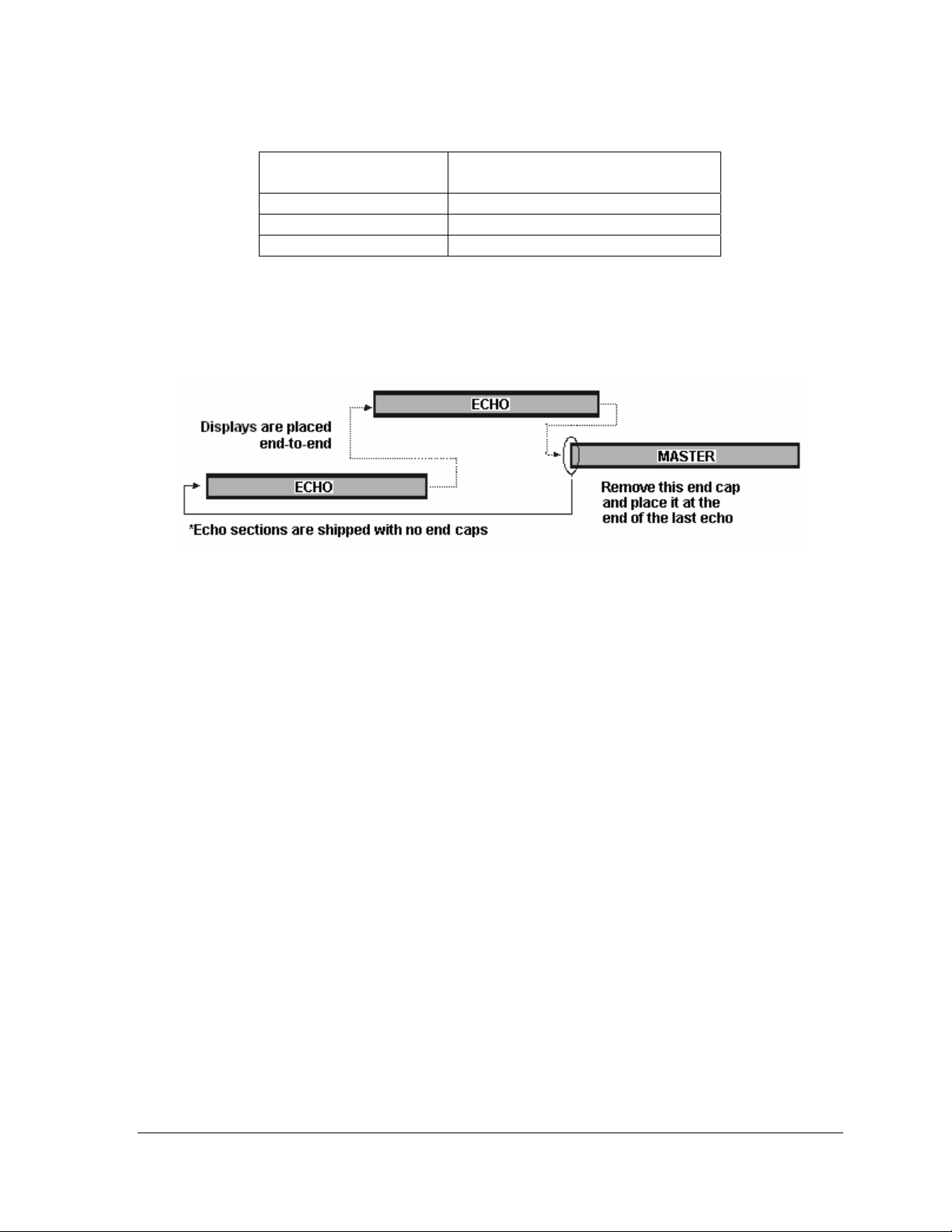
Mounting Multi-section Tickers
The echo sections are shipped without end caps. Remove the left outer end cap from the
master ticker and attach it to the left-most echo ticker (refer to Figure 8).
Figure 8: Master-Echo Installation Detail
1. Before attempting to connect the sections, check their mounted alignment in relation
to each other. If the alignment is off, then adjust the mounting clips on the back of
the tickers.
2. Hang each section according to the appropriate mounting directions.
3. Refer to Section 3 for routing power and Section 4 for signal installation to each
section.
4. Slide the sections together.
5. Slide the splice bar over the joint(s) between the displays.
6. Tighten the screws (provided in the splices) using a 3/16" hex wrench.
Mechanical Installation 5
Page 12

Page 13
Section 3: Power Installation
• Only a qualified individual should terminate power and signal cable at this Daktronics
display.
• All proposed changes must be approved by Daktronics engineering staff or the
warranty will be rendered null and void.
Reference Drawings:
Power Specs, GEN II, KE-101
Shop Drawings........................................................................................................in Appendix A
Schematics..............................................................................................................in Appendix A
3.1 Power Requirements
The displays accept a universal input voltage of 100-240 VAC at 50-60 Hz. Refer to the
following table and the drawings referenced at the beginning of the section for voltage and
current requirements. The displays are sufficiently powered by a 100-240 VAC single-phase
outlet. Refer to Drawing A-234168 for the power specifications for individual DakTicker
display sizes.
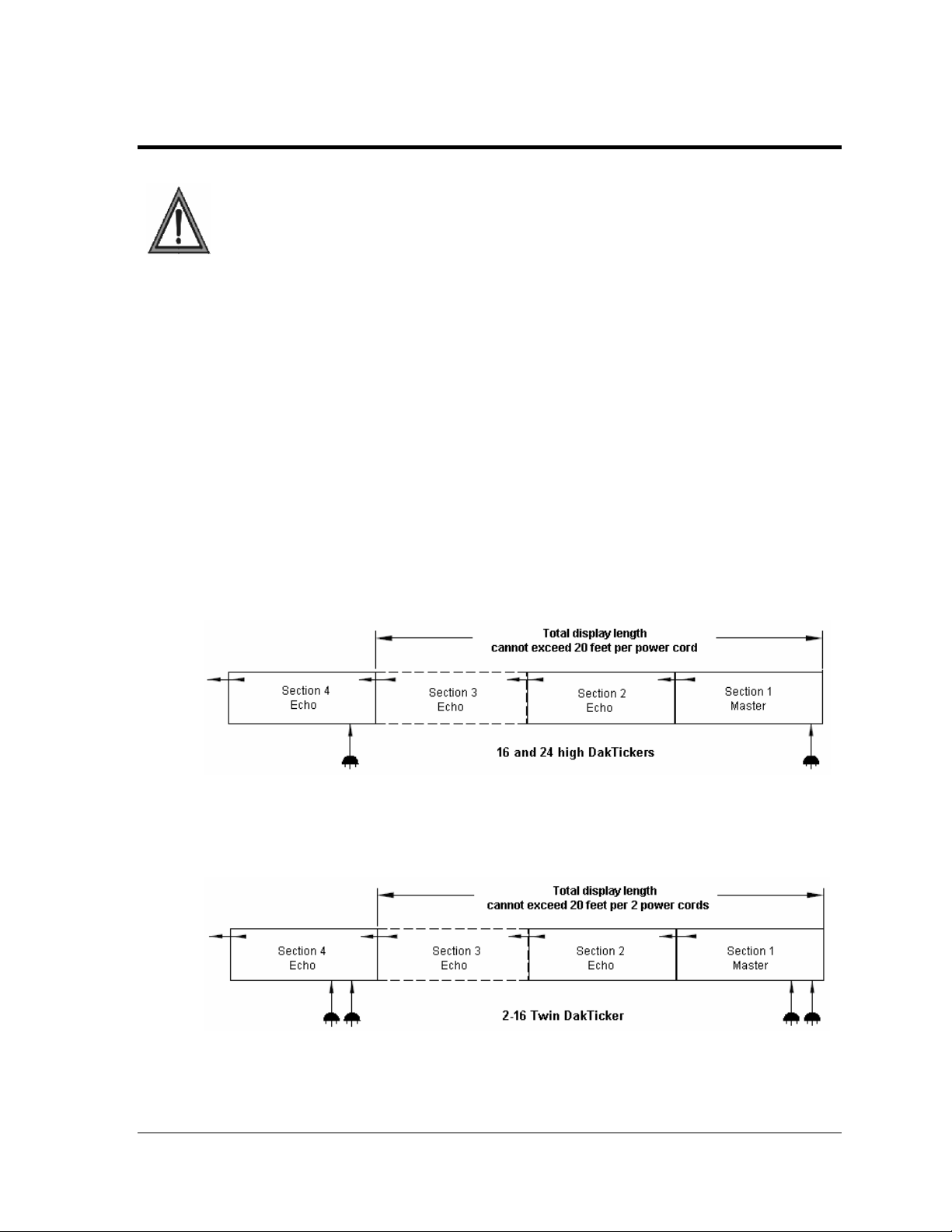
No more than two additional sections may be powered from one powered section. Total
display length powered from one section is not to exceed 20 feet (6.1 M).
*-16x***, 24x***, 2-16*** .................................... Drawing A-234168
Figure 9: 16 and 24 High DakTickers Power Connection
Figure 10: 16 High Twin DakTicker Power Connection
Power Installation 7
Page 14
Power Specifications for Tickers with Multiple Sections
# of Phases 16 and 24 High Twin 16 High
Amps Per Line
(100-240VAC)
Max Watts
6.9 (Sum of 3 Sections) 13.8 (Sum of 3 Sections)
825 Watts (Sum of 3 Sections) 1650 Watts (Sum of 3 Sections)
Voltage – Secondary
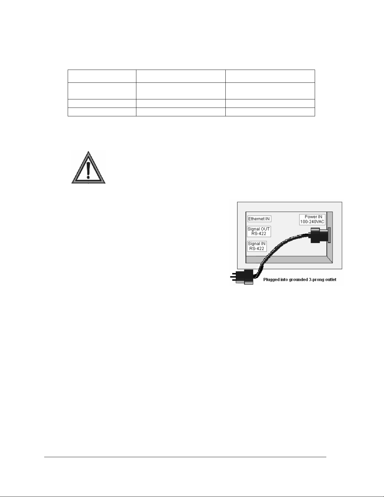
3.2 Power Cord - Grounding
Note: Most products are equipped with a 3-wire grounding-type
plug—a plug having a third (grounding) pin. This plug will only fit into
a grounding-type power outlet. This is an essential safety feature. If
the correct outlet is not available for this plug, contact a qualified
of the grounding-type plug.
The DakTicker displays are each supplied with a sixfoot long removable power cord. The socket-outlet
should be available near the equipment and easily
accessible. Plug the power cord into the socket on the
back of the display, as shown in Figure 11.
Note: No more than two additional display sections can
be powered from this section. Total length of the
display cannot exceed 20 feet (6.1 M)
If proper grounding methods are not followed, the
warranty will be void.
electrician to replace the obsolete outlet. Do not defeat the purpose
5VDC 5VDC
Figure 11: Power Cord Connection
8
Power Installation
Page 15
Section 4: Signal Installation
To display messages on a KE-1010 display, signal is sent from the computer to the ticker via one of
two possible network systems: RS-422 or Ethernet. Signal is received by the controller board inside
the master section of the ticker. The controller board processes the data and relays it to the shift card.
The shift card relays signal to the modules, then the appropriate LEDs create the messages which
scroll across the ticker display.
Reference Drawings:
Concept System Riser Diagram TCP/IP......................................................... Drawing A-229840
Concept System Riser Diagram RS-422........................................................ Drawing A-229912
Schematics..............................................................................................................in Appendix A
4.1 Network Options
RS-422 Connections
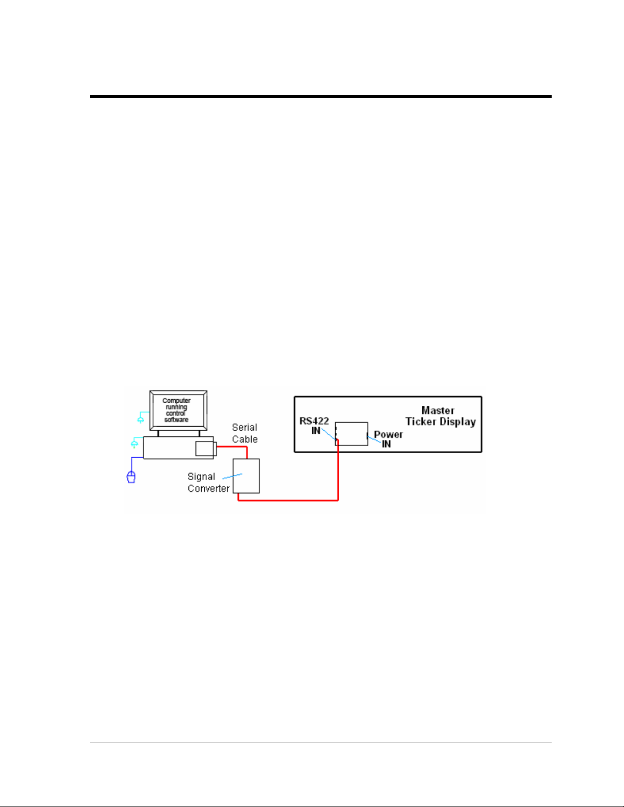
An RS-422 communication system requires a signal converter to change the computer’s RS232 output into RS-422 signal for the controller. The typical maximum cable length is 1.2km
(approximately 4,000 feet). Refer to Appendix B for information on the signal converter.
Refer to Figure 12 for an overview of this communication layout.
Figure 12: RS-422 Signal Layout
To connect RS-422 signal, follow these steps:
1. Plug the serial cable’s 25-pin connector into the signal converter.
2. Plug the 9-pin connector into the RS-232 COM port to be used.
3. Plug the signal converter’s power cord into a grounded outlet.
Note: The signal converter requires a specific supply voltage of 120 or 240 VAC.
4. Plug a flipped 6-conductor RJ11 cable into the “RS-422 OUT” of the signal converter
and the opposite end into the “RS-422 IN” of the master section.
5. Plug the ticker’s power cord into a 100-240 VAC grounded outlet.
Signal Installation 9
Page 16
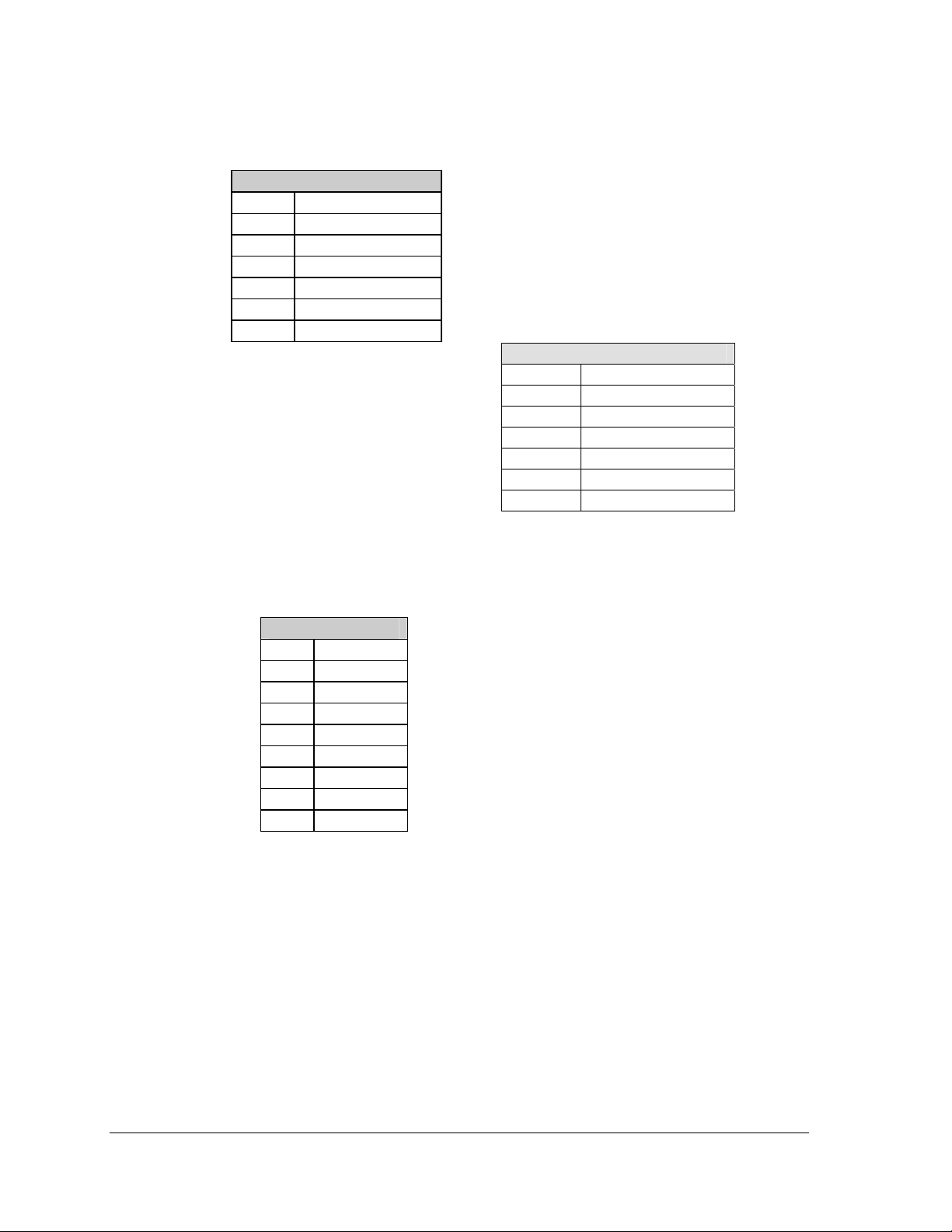
RS-422 Pin-outs
The controller’s RS-422 jacks have the following pin-outs:
Signal Converter Pin-outs
The signal converter has two RS-422 output jacks, with the following pin-out:
INPUT (J4)
RJ11 Function
1 N.C.
2 D1OUT-P
3 D1OUT-N
4 D1IN-P
5 D1IN-N
6 N.C.
OUTPUT (J5)
RJ11 Function
1 N.C.
2 D2OUT-N
3 D2OUT-P
4 D2IN-N
5 D2IN-P
6 N.C.
OUTPUT
RJ45 Function
1 N.C.
2 CHGND
3 TX.A-N
4 TX.A-P
5 RX.A-N
6 RX.A-P
7 CHGND
8 N.C.
10
Signal Installation
Page 17
Ethernet Connections
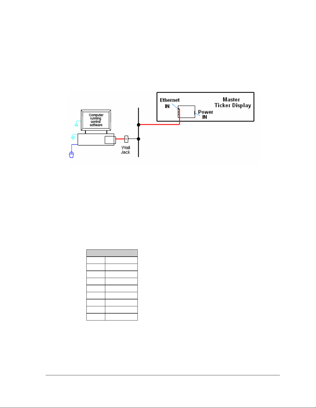
For DakTickers using an Ethernet system for communication, a network connection will be
made from the network hub or switch to the master section. The Cat-5/Cat-5E cable has a
typical maximum length of 100 meters (approximately 300 feet). The controller has an
onboard Ethernet port with a default address that will need to be reconfigured to an address
on the local network. Refer to Appendix C. The default address is 172.16.192.27.
Figure 13: Ethernet Signal Layout
Follow these steps to set up the Ethernet system:
1. Plug the computer into a network hub.
2. Plug the network cable into a network hub or switch.
3. Plug the other end of the RJ45 network cable into the jack labeled “Ethernet IN” on
4. Plug the ticker’s power cord into a 100-240 VAC grounded outlet.
Ethernet Pin-outs
The controller’s Ethernet input jack has the following pin-out:
the controller in the master section.
INPUT (J6)
RJ45 Function
1 TX+
2 TX3 RX+
4 EPWR+
5 EPWR+
6 RX7 EPWR8 EPWR-
Signal Installation 11
Page 18
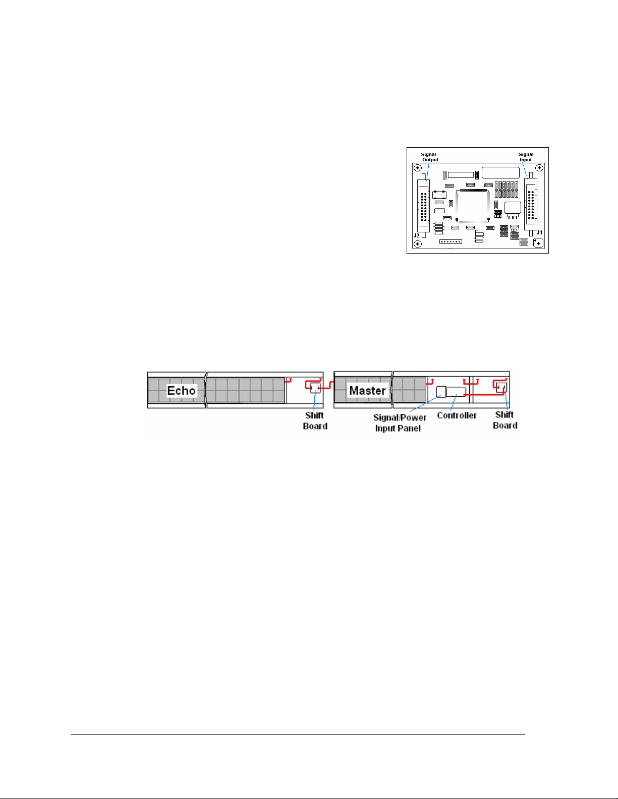
4.2 Section to Section Connections
The signal between the master and echo sections is connected using 20-pin ribbon cables
between the shift board and the last module of the previous section (Figure 15). Follow these
steps to connect display sections.
1. Carefully hang the echo section(s) as described in
Section 2.2. Do not yet slide the sections together.
2. A ribbon cable should already be plugged into the
“Signal In” jack on the shift board (Figure 14) of the first
echo section. If it isn’t, do so at this time.
3. Plug one end of the ribbon cable into the “Out” jack on
the back of module A101 (the left end module) of the
master section.
4. If an echo section is present, plug P42/P43 of the echo
section into J42/J43 of the master section to complete
the interconnection of power. Repeat this for additional sections. Note: Total display
length cannot exceed 20 feet per power cord.
5. The connection for a master to one echo is shown in Figure 15. Repeat steps 1 though
3 to connect and hang each consecutive echo ticker. All other internal wiring
between modules has been done by Daktronics.
Figure 14: Shift Board
Figure 15: Master to Echo Connection
4.3 Master to Master Connections
In some cases, more than one master display is used instead of the master-echo
configuration. In this case, signal can be transmitted between master displays using a flipped
6-conductor RJ11 cable running RS-422. To connect multiple master displays:
1. Signal into the first display can be either RS-422 or Ethernet.
2. Connection between displays will always be RS-422. Connect from RS-422 OUT on
the first display to RS-422 IN on the second display (Figure 16).
3. Master displays connected in this way will need to have different addresses set on
each controller.
12
Signal Installation
Page 19
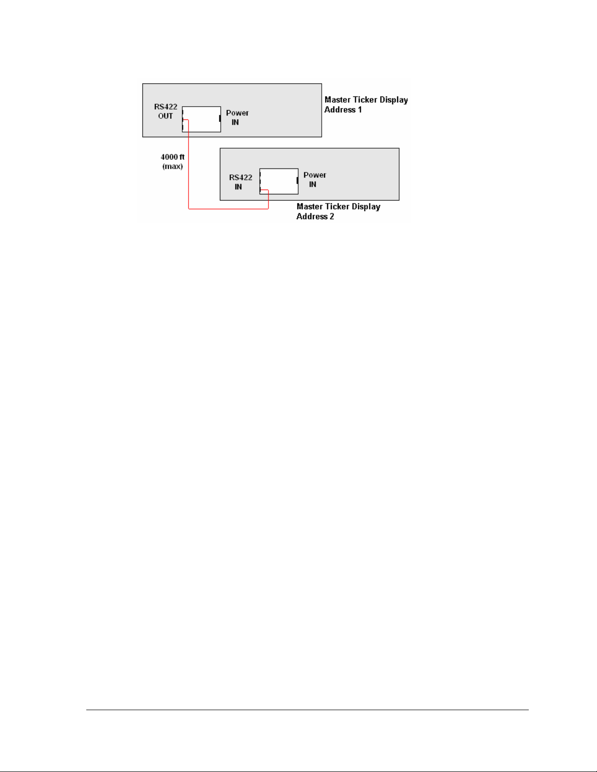
Figure 16: Master to Master RS-422 Connection
4.4 Installation Checklist
After installation is complete, go over these steps to make sure that the display is properly
connected and ready to operate correctly.
1. Carefully check the voltage between the hot lines and neutral. Normal voltage range
is between 100 VAC and 240 VAC.
2. If problems arise with the voltage, check with a local electrician or power company.
3. Plug the power cord(s) from the ticker(s) into a grounded 100-240 VAC single-phase,
grounded outlet(s).
4. Turn power ON to the outlet(s).
4.5 Boot Up Sequence
Each time the KE-1010 is powered up, the following information is shown on the display
face. The Xs represent numbers that will change according to the specific installation.
• DakTicker by Daktronics
• ED10288
• REV X
• ADDRESS XX
• IP Address
Signal Installation 13
Page 20

Page 21

Section 5: Maintenance and Troubleshooting
This section covers the basic maintenance needed to keep the display operating effectively. Also
included are diagnostic and troubleshooting information to pinpoint display problems and provide
solutions. Following this are definitions of terms used in the manual.
• Disconnect power before any repair or maintenance work is done on the display!
• Qualified service personnel must make any access to internal display electronics.
• Disconnect power when the display is not in use.
5.1 Display Maintenance
Controller Diagnostic LEDs
The ticker controller has four LEDs that indicate whether the controller is functioning
properly. Note that the transmit and receive LEDs will toggle on and off a few times when
the controller is first establishing communication.
LED Name Label Indication
Power PWR On constantly when operating correctly.
Run RUN Blinks at a rate of every half second when power is on.
Receive RXD Flashes each time data is received.
Transmit TXD
Flashes when sending data from the controller to the
computer. Most of the time, this LED is off.
Figure 17: Controller with Diagnostic LEDs
Maintenance and Troubleshooting 15
Page 22

Visual Structural Inspection
At least once a year, check the display to make sure that the structure and components are in
good condition. Inspect the paint and cabinet for corrosion. Make sure that fasteners are
tight; if not, tighten or replace as required.
5.2 Troubleshooting
This chart lists some symptoms that may be encountered with the ticker displays. For each
symptom, possible causes and corrective actions are indicated. This list does not include
every possible problem but does represent some of the more common situations that may
occur.
Symptom/Condition Possible Cause/Remedy
A single pixel on the display will not light. • Check signal connection.
One or more LEDs will not turn off. • Check signal connection.
Section of display is not working. • Check power to the section.
Display is garbled or sequence is shifted. • Check the data settings on the computer.
A group of modules does not work. • Check for output from power supplies.
Entire display does not work. • Check 100-240 VAC input power to 1st section.
Data feed or software is not operating
properly.
Display resets and restarts. • Reduce the amount of amber pixels used.
• Replace the module.
• Replace the module.
• Check for input power to the module.
• Replace ribbon cable.
• Replace/move the first module not working.
• Replace/move the last working module of the
previous section.
• Check power supply.
• Replace shift card.
• Replace the controller.
• Check signal connections.
• Refer to the data feed manual.
• Reboot power to the section.
• Check/replace ribbon cable.
• Replace/move the first module not working.
• Replace/move the last working module of the
previous section.
• Check signal connections.
• Check all signal connections.
• Check PC/Feed setting for proper orientation.
• Replace controller.
• Refer to data feed manual.
• Check signal connection feed to display.
• Contact data feed/software provider.
• Remove inverted text.
16
Maintenance and Troubleshooting
Page 23

5.3 Definitions
Cabinet: The metal frame of the display (back, bottom, top); may also include the end caps.
Column: A vertical line of pixels.
Controller: The component i
the computer’s ticker feed.
End Cap: A metal plate that covers each end of a ticker.
Ethernet: A standard communication interface that utilizes a local area network (LAN). The
m
aximum cable length is 300 feet (100 meters).
Face Panel: The tra
LED: (Light
the ticker display.
Module: A 16 x 40 or 24 x 40 array of LEDs. Modules m
display unit.
Pixel: A single p
RS-232: A sta
meters).
RS-422: A st
feet (1.2 kilometers).
Row: A horizont
Shift Board: R
ticker sections.
Signal Converter: A Dakt
The signal converter is connected to the control PC via a straight through serial cable.
Emitting Diode) A low energy, high intensity lighting unit that shows the text on
oint of light on a display. On the KE-1010, a pixel consists of one LED.
ndard PC communication type with a maximum cable length of 25 feet (7.6
andard differential communication type with a maximum cable length of 4,000
al line of pixels.
elays the signal from the controller board to the first module and then between
n the master section that receives and interprets the data from
nsparent polycarbonate panel that sits in front of the modules.
ay be individually removed from the
ronics supplied unit that converts the data from RS-232 to RS-422.
Maintenance and Troubleshooting 17
Page 24

Page 25

Section 6: Parts Replacement
• Disconnect power before any repair or maintenance work is done on the display!
• Qualified service personnel must make any access to internal display electronics.
• Disconnect power when the display is not in use.
DakTicker displays are built for long-term reliable operation; however, on occasion parts may need
to be replaced. (Components within the displays are not field repairable.) To access internal
components, modules may easily be removed. This section provides instructions for removing
modules and replacing basic components.
Reference Drawings:
Component Layout Drawings.................................................................Inserted into Appendix A
Shop Drawings............................................................................................. Listed in Appendix A
Schematics................................................................................................... Listed in Appendix A
6.1 Replacement Parts List
The following part labeling formats might be found on various Daktronics drawings. These
part numbers can be used when requesting replacement parts from Daktronics Customer
Service.
• “TB__” denotes a termination block for power or signal cable.
• “F__” denotes a fuse.
• “E__” denotes a grounding point.
• “J__” denotes a power or signal jack.
• “P__” denotes a power or signal plug for the opposite jack.
• “0P-_ _ _ _-_ _ _ _” shows an individual circuit board, such as the internal shift card.
• “0A-_ _ _ _-_ _ _ _” indicates an assembly, such as a circuit board and the plate or
bracket to which it is mounted. A collection of circuit boards working as a single unit
may also carry an assembly label.
• “W-_ _ _ _” represents a wire or cable. Cables may also carry the assembly
numbering format in certain circumstances, such as ribbon cables.
Most circuit boards and components within this display carry a
label that lists the part number of the unit. If a circuit board or
assembly is not listed in the Replacement Parts List, use the
label to order a replacement. A typical label is shown in Figure
18 with the part number in bold.
Figure 18: Typical Label
Parts Replacement 19
Page 26

Consult this list for the Daktronics part number for basic display components. Refer to
Section 6.4 for inst
ructions on obtaining parts from Daktronics.
Part Description Daktronics Part #
Controller Board (16-high, RS-422 Input) 0P-1182-0011
Controller Board (16-high, RS-422 or Ethernet Input) 0P-1182-0022
Controller Board (24-high, RS-422 or Ethernet Input) 0P-1182-0023
Shift Board (16-high) 0P-1182-0012
Shift Board (24-high) 0P-1182-0019
Module; 16x40 Super Bright Red-Green 0P-1182-0014
Module; 24x40 Super Bright Red-Green 0P-1182-0018
Signal Converter; RS232 to RS-422, 120V 0A-1127-0255
Serial Cable, DB9 to DB25, from PC to Signal Converter W-1249
Ribbon Cable; 20 Cond. 28 AWG (Between Modules) W-1357
Ribbon Cable; 20 Cond. 28 AWG
(Controller to shift card and shift card to module)
Power Supply; +5VDC A-1632
Power Cord; 3-Prong 120VAC W-1181
Splice Bar EN-1772
Mounting Clip, KE-1010-**x***-7.62 0M-233464
Suction Cup, 2 ¼” Dia. HS-1338
Filter; RFI Line Z-1014
Face Panel; 16x240 0A-1182-0015
Face Panel; 16x320 0A-1182-0016
Face Panel; 16x400 0A-1182-0017
Z-Mounting, GEN II, KE-1010-**x120-7.62 0M-233463
Z-Mounting, GEN II, KE-1010-**x160-7.62 0M-234569
Z-Mounting, GEN II, KE-1010-**x200-7.62 0M-234704
Z-Mounting, GEN II, KE-1010-**x240-7.62 0M-234712
Z-Mounting, GEN II, KE-1010-**x280-7.62 0M-234719
Z-Mounting, GEN II, KE-1010-**x320-7.62 0M-234723
Z-Mounting, GEN II, KE-1010-**x360-7.62 0M-234728
Z-Mounting, GEN II, KE-1010-**x400-7.62 0M-234733
Z-Mounting, GEN II, KE-1010-24x***-7.62 0M-235529
DataStreamer Manual ED-13649
W-1387
20
Parts Replacement
Page 27

6.2 Removing the Face Panel
The internal components of the KE-1010 displays may be accessed after the face panel and
modules are removed. Refer to Figure 19 for a visual diagram of the steps involved in
removing the face panel. Never attempt to lift the entire display or carry the face panel using
the suction cups.
To remove the face panel:
1. Disconnect power to the display.
2. Using the suction cups provided with the display, slide the face panel up toward the
top of the display (Figure 19).
3. Pivot the bottom edge of the panel out of the support groove. The face panel should
now be free of the display cabinet.
4. Carefully remove the face panel. The LED modules will now be accessible.
5. Remove the appropriate module to access the internal electronic components.
To replace the face panel, follow the previous steps in reverse order.
Note: When replacing the face panel, it may be slightly wavy and not slide neatly down into
the groove. If the face panel is not easily reinserted, then start at one end of the display and
gently press your hand against the bottom edge of face panel to slide it into the bottom
support groove.
Figure 19: Removing the Face Panel
Parts Replacement 21
Page 28

6.3 Instructions for Replacing Parts
LED Module Replacement
To remove and replace an LED module:
1. Disconnect the main supply power to the section
being serviced.
2. Remove the face panel as described in Section 6.2.
3. Each module is held in place by 5/16”hex nuts at
six locations. Remove the securing nuts (refer to
Figure 20).
4. Carefully lift the module out of the display. Note:
All power and signal cables are still connected
(Figure 21).
5. Disconnect the cables from the back of the module,
noting their location. The module is then no longer
attached to the display.
6. Follow the previous steps in reverse order to
reattach a module. Refer to the Schematic for
additional wiring information.
Figure 20: Detaching a Module
22
Figure 21: Removing a Module
Parts Replacement
Page 29

Power Supply Replacement
Power to the LED modules is provided by +5 VDC power supplies. To remove a power
supply:
1. Disconnect the main supply power to the section requiring service.
2. Remove the face panel per Section 6.2.
3. Remove the LED module in front of the failed power supply. Refer to the
appropriate Component Layout Drawing for the location of the power supplies.
4. The plate is secured to the back sheet by two (2) #6 nuts. Remove the #6 nuts to
remove the plate with the power supply. Lift the power supply and plate out of the
display.
5. Each power supply is attached to a
mounting plate by two (2) M4x8MM
metric screws. Using a #1 Philips
screwdriver, remove the screws to free
the power supply.
6. Disconnect all power supply wires,
noting their connections (Figure 22). The
power supply is now ready for
replacement.
7. Follow the previous steps in reverse
order to reattach the new power supply.
Figure 22: Power Supply Wiring
Shift Card Replacement
The shift cards are used to relay signal from the controller to the modules or from the last
module of the previous section to the LED modules in the next section. One shift card is
located in the right end of each KE-1010 section (both master and echo). To replace a shift
card:
1. Disconnect the main supply power to the
section requiring service.
2. Remove the face panel per Section 6.2.
3. Remove the last module in the right end
of the selected ticker section.
4. Remove signal cables from the shift card,
noting the correct connections (Figure
23).
5. The card is attached to the inside of the
display with four #6-32 hex-head screws.
Remove the attaching screws and
carefully lift the card from the display.
6. If a jumper is present, make sure it is in
the same location as the board being replaced.
7. Follow the previous steps in reverse order to attach a new shift card. Refer to the
appropriate display Schematics for wiring information.
Figure 23: Shift Board
Parts Replacement 23
Page 30

Controller Replacement
The controller is mounted inside the master display on the back of the cabinet (Figure 24). It
is typically located behind the second module from the right end. The display controller
receives information from the ticker input, interprets it, and activates
LEDs. The controller has a set of eight switches, the first four of which are used to set the
hardware address using standard binary code. Refer to the following section for instructions
on setting the address. Display controllers are found only in master displays.
Figure 24: Display Controller
To replace a controller:
1. Disconnect the main supply power to the master section.
2. Remove the face panel per Section 6.2.
3. Remove the two LED modules on the right end of the master section.
4. Remove all power and signal cables to the controller, noting their connections.
(Signal to the controller may also be connected from the back of the display.)
5. The controller is attached to the inside of the display with four #6-32 hex-head
screws. Remove the attaching screws and carefully lift the controller from the
display.
6. Follow the previous steps in reverse order to attach a new controller. Refer to the
appropriate display Schematic for wiring information.
Note: Be sure to set the new controller’s address to the same settings as the one it is
replacing. Refer to the following information.
the corresponding
24
Parts Replacement
Page 31

Controller Address
The controller has a set of “DIP” switches or address switches, as shown in Figure 24. These
switches set the hardware address for the display system. When replacing a controller board,
be sure to set the DIP switches on the new controller to the same address configuration as the
controller which was removed.
Note: DIP Switches 1-4 are used for addressing, while swit
6, and 8 are not used.
Switch 7 Switch 4 Switch 3 Switch 2 Switch
Off Off Off Off Off 0
Off Off Off Off On 1
Off Off Off On Off 2
Off Off Off On On 3
Off Off On Off Off 4
… … … … … …
Off On On On Off 14
Off On On On On 15
ch 7 enables test mode. Switches 5,
1
Address
On Off Off Off Off Test Mode
6.4 Daktronics Exchange and Repair & Return Program
To serve customers’ repair and maintenance needs, Daktronics offers both an Exchange
Program and a Repair & Return Program.
Exchange Program
Daktronics unique Exchange Program is a quick service for replacing key parts in need of
repair. If a part requires repair or replacement, Daktronics sends the customer a replacement,
and the customer sends the defective part to Daktronics. This decreases display downtime.
Before Contacting Daktronics
Insert important part numbers here:
____________________________________________________________
____________________________________________________________
____________________________________________________________
Fill in these numbers before calling Customer Service:
Display Serial Number: _____________________________________________
Display Model Number: _______KE-1010 DakTicker 7.62 mm
Contract Num
ber: ___________________________________________________
Date Installed: ______________________________________________________
Location of Disp
Daktronics Customer ID Num
lay: _________________________________________________
ber: _____________________________________
____________
Parts Replacement 25
Page 32

To participate in the Exchange Program, follow these steps:
1. Call Daktronics Custom
2. When the new exchange part is received, mail the old part to Daktronics.
If the replacement part fixes the problem, send in the part which is being replaced.
a. Package the old part in the same shipping materials in which the replacement
part arrived.
b. Fill out
c. Shi
3. A charge will be m
service agreement is in place.
In most circumstances, the replacement part will be invoiced at
4. If the replacem
working days or the full purchase price will be charged.
If the equipment is still defective after the exchange was made, please contact
Customer Service immediately. Daktronics expects immediate return of an exchange
part
if it does not solve the problem. The company also reserves the right to refuse
parts that have been damaged due to acts of nature or causes other than normal wear
and tear.
and attach the enclosed UPS shipping document.
p the part to Daktronics.
ent part does not solve the problem, return the part within 30
er Service: 866-343-3122
ade for the replacement part immediately, unless a qualifying
the time it is shipped.
Repair & Return Program
For items not subject to exchange, Daktronics offers a Repair & Return Program. To send a
part for repair, follow these steps:
1. Call or fax Daktronics Customer Service:
Phone: 866-343-3122 Fax: 605-697-4444
2. Receive a Return Materials Authorization (RMA) number before shipping.
This expedites repair of the part.
3. Package and pad the item
Electronic components, such as printed circuit boa
antistatic bag before boxing. Daktronics does not recommend Styrofoam peanuts in
packaging.
4. Enclose:
• your name
• address
• phone number
• the RMA number
• a clear description of symptoms
Shipping Address
Daktronics Customer Service
PO Box 5128
331 32nd Avenue
Brookings, SD 57006
carefully to prevent damage during shipment.
rds, should be placed in an
26
Parts Replacement
Page 33

Appendix A: Reference Drawings
Drawings are inserted here according to this list, with generic drawings first, followed by
Component Layout, Schematic, and Shop Drawings. Under each category, drawings are inserted by
matrix size.
General Drawings
Mounting Drawing, Ceiling, KE-1010-16x***-2.1
Shop DWG, Mounting, GEN II, Splice Bar, KE-1010
Concept System Riser Diagram TCP/IP
Concept System Riser Diagram RS/422
Mounting Clip, GEN II, KE-1010-**x***-7.62
Power Specs, Gen II, KE-101*-16x***,24x***, 2-16x***
Shop DWG, Horiz Wall Mount, GEN II KE-1010 Ticker
Shop DWG, Vert Wall Mount, GEN II
Drawings listed by matrix size:
Component Layout, KE-1010-16x***-7.62............................................................. Draw
Component Layout, KE-1010-24***-7.62
Component Layout, KE-1010-2-16x***-7.62
Schematic: GEN II, KE-101*-**x120-7.62-RG
Schematic: GEN II, KE-101*-**x160-7.62-RG
Schematic: GEN II, KE-101*-**x200-7.62-RG
Schematic: GEN II, KE-101*-**x240-7.62-RG
Schematic: GEN II, KE-101*-**x280-7.62-RG
Schematic: GEN II, KE-101*-**x320-7.62-RG
Schematic: GEN II, KE-101*-**x360-7.62-RG
Schematic: GEN II, KE-101*-**x400-7.62-RG
Shop DWG, GEN II, KE-1010-16x120/160/200/240
Shop DWG, GEN II, KE-1010-16x280/320/360/400
Shop DWG, GEN II, KE-1010-2-16x280/320/360/400
Shop DWG, GEN II, KE-1010-2-16x120/160/200/240
Shop DWG, GEN II, KE-1010-24x120/160/200/240
Shop DWG, GEN II, KE-1010-24x280/320/360/400
................................................... Drawing A-118572
............................................ Drawing A-118728
............................................................... Drawing A-229840
............................................................... Drawing A-229912
......................................................... Drawing A-233464
........................................ Drawing A-234168
........................................ Drawing A-234483
KE-1010-24x*** ......................................... Drawing A-234529
ing A-302699
.............................................................. Drawing A-302700
......................................................... Drawing A-302701
....................................................... Drawing B-234114
....................................................... Drawing B-234115
....................................................... Drawing B-234122
....................................................... Drawing B-233964
....................................................... Drawing B-234634
....................................................... Drawing B-234635
....................................................... Drawing B-234636
....................................................... Drawing B-234637
............................................. Drawing B-237159
............................................. Drawing B-118077
.......................................... Drawing B-210277
.......................................... Drawing B-237160
............................................. Drawing B-237161
............................................. Drawing B-214329
Reference Drawings 27
Page 34

Page 35

Page 36

Page 37

Page 38

Page 39

Page 40

Page 41

Page 42

Page 43

Page 44

Page 45

Page 46

Page 47

Page 48

Page 49

Page 50

Page 51

Page 52

Page 53

Page 54

Page 55

Page 56

Page 57

Appendix B: Signal Converter
Signal Converters and Loop-back Testing for Direct Connections
The following table gives the typical state of the signal converter when the LEDs are either on or off.
Refer t
o Figure 25 for an illustration of the signal converter and the location of the various
components.
LEDs Typical States Troubleshooting
ON Signal Converter (SC) is receiving power
Power
TX
RX
TX/RX
OFF
On Steady
OFF
Steady
Brief
Flicker
ON Steady
OFF
Steady
Brief
Flicker
ON Steady
Signal Converter is not receiving power Check power/Replace fuse
Internal 1 AMP fuse is bad Replace fuse
Signal Converter is not connected to a
serial port
1. Serial port or serial cable is bad
2. Computer COM port is in sleep mode
Normal state, Signal Converter is not
transmitting data
SC is transmitting data
1. Field cabling between Signal Converter
and display is bad
2. Is connected to display output jack or
terminated incorrectly
3. Bad COM port is on display controller
Normal state, Signal Converter is not
receiving data
SC is receiving data
(If serial cable is connected) Bad Signal
Converter
Connect to open computer
COM port
1. Try another port or replace
serial cable
2. Communicate with display
1. Eliminate cabling by
disconnecting wire/cable
from SC to dis
2. Check connections and
terminations
3. Eliminate by disconnecting
wire/cable to display
controller
Replace Signal Converter
play controller
Signal Converter 29
Page 58

RS-422 Wire Signal Converter
The
following tables list the jack pin-outs for a wire signal converter:
PIN OPERATIO
Figure 25: RS-232 to RS-422 Signal
Converter
PIN OPERATION
1
2
3
4
5
6
J1 – 25 Pin DB-F
PIN OPERATION
2
3
7
J4 and J5 –
Phoenix
GND
1
RX-P (in)
2
RX-N (in)
3
TX-P (out)
4
TX-N (out)
5
GND
6
J2 and J3 –
RJ/11
GND
TX-N (out)
TX-P (out)
RX-N (in)
RX-P (in)
GND
TX-P (out)
RX-P (in)
GND
N
30 Signal Converter
Page 59

RS-422 Loop-Back Test (Indoor/Outdoor Displays)
All indoor displays and some outdoor displays (AE-3010, AF-3010, AF-3020, and X-1000) use
RJ11 plugs or connectors. In those cases, a “Network Cable Tester” is provided to conduct
the test.
The network cable tester is used to test for two things:
• verify that a flipped RJ11 cable is being used.
• verify that a good connection is made from a computer or signal converter.
The use of a flipped (reversed) or straight cable can be determined visually. Use the figures
below as a guide, or use the Network Cable Tester box for assistance.
Figure 26: Flipped Cable (Reversed)
Figure 27: Straight Cable
1. Plug one end of the flipped cable into the output from the computer or signal
converter.
2. Plug one end of the flipped cable into J2 (Loopback Connector) on the network cable
tester box.
3. When both ends are
connected, perform the loopback test using the Venus 1500
software as described in
Section 1.4.
Figure 28: Network Cable Tester
Signal Converter 31
Page 60

Electrical and Signal Information
WARNINGS:
• Never inst
• Never touch uni
been disconnected at the network interface.
• Avoi
There may be a remote risk of electrical shock from lightning.
• To reduce the risk of fire, use only 26AWG or larger telecommunication line cord.
• This product is to be used with UL and c-UL listed computers.
Electrical Ratings
The Signal Converter is rated for either 120 or 240 VAC power in and a maximum draw of 5
watts. Refer to the parts descriptions in Section 2.3.
Power Disconnect
The power cord serves as the disconnect device and the socket outlet must be installed near
the equipment and must be easily accessible.
Parts Listing
The following parts may need replacing during the life of the component.
Servicing should be conducted by qualified personnel only.
all telephone wiring during a lightning storm.
nsulated telephone wires or terminals unless the telphone line has
d using a telephone (other than a cordless type) during an electrical storm.
Part Description Part Number
RS-232-422 Signal Converter, 120 V 0A-1127-0255
RS-232-422 Signal Converter, 240 V 0A-1127-0257
Fuse; AGC-1, 1A, Glass Tube 250 V F-1019
6 Pin Fem, 5 mm, TB Mate, Screw P-1051
Environmental Rating
The signal converter is made for indoor operations and is rated for indoor use only.
32 Signal Converter
Page 61

Mounting Instructions
The signal converter can be either wall or table mounted. Do not mount the signal converter
from the ceiling or the underside of a table.
To mount the signal converter, refer to drawing B-200645. Secure the signal converter using a
screw through the mounting holes at the back of the enclosure. Do not fully tighten the
screws.
Figure 29: Signal Converter Enclosure
Signal Converter 33
 Loading...