

Page 1

i
and all other trademarks used in this manual are trademarks of their respective companies.Customer:
Horn Start HS-200
Owner’s Manual
ED-12935 Rev 14 – 16 January 2013
201 Daktronics Drive PO Box 5128 Brookings, SD 57006-5128
Tel: 1-800-DAKTRONICS (1-800-325-8766) Fax: 605-697-4746
www.daktronics.com
Contract: ____________________
Model Number: _______________
Serial Number: _______________
Table of Contents
Page 2

Page 3

ED-12935
Product 1056
Rev 14 – 16 January 2013
DAKTRONICS, INC.
Copyright 2007-2013
All rights reserved. While every precaution has been taken in the preparation of this manual, the publisher
assumes no responsibility for errors or omissions. No part of this book covered by the copyrights hereon may be
reproduced or copied in any form or by any means – graphic, electronic, or mechanical, including photocopying,
taping, or information storage and retrieval systems – without written permission of the publisher.
OmniSport® is a registered trademark of Daktronics, Inc. All other trademarks used in this manual are trademarks of
their respective companies.
Page 4

Page 5

i
Table of Contents
Section 1: Introduction ................................................................................................................. 1
1.1 About This Manual ................................................................................................................. 1
1.2 Horn Start Overview .............................................................................................................. 1
1.3 HS-200 Wireless Microphone – FCC Compliance Statement ............................................ 2
1.4 Important Safety Instructions ................................................................................................ 2
1.5 Specification Label .................................................................................................................. 3
1.6 Using the Horn Start ............................................................................................................... 3
Before Each Session ......................................................................................................... 3
During Competition ........................................................................................................ 3
After the Competition ..................................................................................................... 3
Section 2: System Setup & Operations ...................................................................................... 5
2.1 HS-200 Indicators, Switches, Knobs & Connections .......................................................... 5
2.2 Start System Setup .................................................................................................................. 7
Connecting the Horn Start .............................................................................................. 8
2.3 Operations ................................................................................................................................ 9
2.4 Battery Operation .................................................................................................................... 9
2.5 Horn Start Settings ................................................................................................................ 10
Enable or Disable Recall On ......................................................................................... 10
Configure Start Sound ................................................................................................... 10
Enable Practice Mode .................................................................................................... 11
Enable or Disable Smart Start ....................................................................................... 11
2.6 Equipment Storage ............................................................................................................... 11
Section 3: Features & Accessories ........................................................................................... 13
3.1 Smart Start .............................................................................................................................. 13
3.2 Practice Mode ........................................................................................................................ 13
3.3 Backstroke Flagpole Bracket ................................................................................................ 13
Attaching the Horn Start to Flagpole .......................................................................... 14
3.4 Remote Strobe ........................................................................................................................ 14
Mounting Bracket & Strap ............................................................................................ 14
Battery Operation........................................................................................................... 14
AC Power Operation & Recharging ............................................................................ 15
Remote Strobe for Training Purposes ......................................................................... 15
3.5 Wireless Microphone Belt Pack ........................................................................................... 15
Using the Wireless Microphone Option ..................................................................... 15
Set Channel Button ........................................................................................................ 16
Wireless Belt Pack Batteries .......................................................................................... 16
HS-200R Internal Radio Module General Operation ................................................ 16
Section 4: Troubleshooting ....................................................................................................... 17
4.1 Troubleshooting Tips ........................................................................................................... 17
Aux or Lane speaker is not working ........................................................................... 17
The microphone is not working ................................................................................... 17
The strobe light does not work .................................................................................... 17
Noise bursts when using the wireless microphone .................................................. 17
Microphone works but the horn start will not Start/Strobe .................................... 17
The recall tone does not sound .................................................................................... 17
The HS-200/HS-200R will not run with battery power ........................................... 18
Table of Contents
Page 6

ii
4.2 Replacement Parts ................................................................................................................. 18
HS-200 Equipment (0A-1056-0116) .............................................................................. 18
HS-200R Equipment (0A-1056-0136) ........................................................................... 18
Optional Equipment ...................................................................................................... 19
Section 5: Daktronics Exchange and Repair & Return Programs .......................................... 21
5.1 Exchange Program ................................................................................................................ 21
Before Contacting Daktronics ...................................................................................... 21
5.2 Repair & Return Program .................................................................................................... 22
Shipping Address .......................................................................................................... 22
5.3 Daktronics Warranty and Limitation of Liability ............................................................. 22
Appendix A: Reference Drawings.................................................................................................. 23
Appendix B: Daktronics Warranty and Limitation of Liability .................................................... 25
Table of Contents
Page 7
1
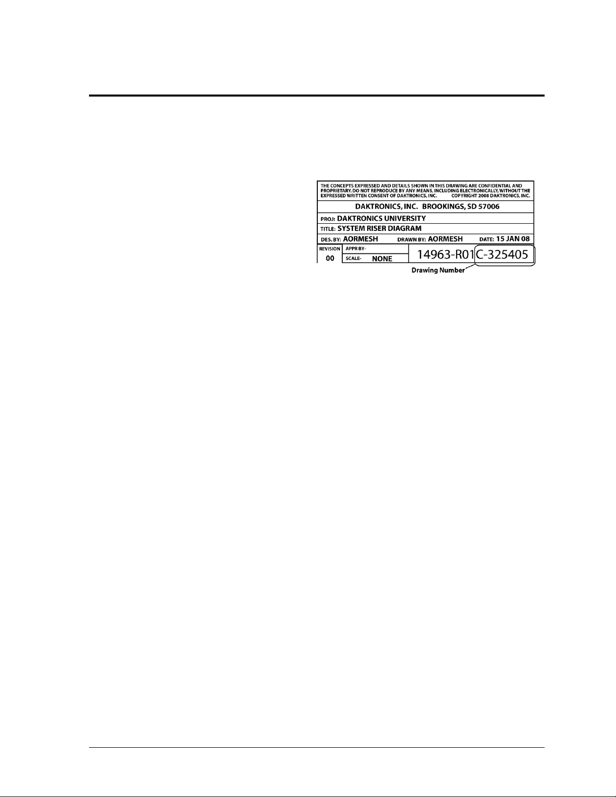
Figure 1: Daktronics Drawing Label
Section 1: Introduction
1.1 About This Manual
The purpose of this manual is to assist with setting up, operating, and troubleshooting the
OmniSport® HS-200 and HS-200R horn start systems.
Figure 1 illustrates a Daktronics
drawing label. The drawing number is
located in the lower-right corner of a
drawing. Drawings are referenced by
the last set of digits and the letter
preceding them. In the example, the
drawing would be referred to as
Drawing C-325405.
All references to drawing numbers, appendices, figures, or other manuals are presented in
bold typeface. Additionally, any drawings referenced within a particular subsection
are listed at the beginning of that subsection in the following manner:
Reference Drawing:
System Riser Diagram ........................................................................... Drawing C-325405
Daktronics identifies manuals by the DD or ED number located on the cover page of each
manual. For example, this manual would be referred to as ED-12935.
1.2 Horn Start Overview
Every heat in swimming has a start. The rulebook states, “The starter should be on a separate
system that is designed specifically to provide clear and simultaneous instructions at each of
the starting platforms.” In addition to needing something to start each heat, many teams train
for starts during practice. A typical beginning of a race starts with the referee or assistant
referee getting the athletes’ attention, then turning control of them over to the start official.
The start official instructs the competitors to “Step-up” for a forward start, or “Place your
feet” for a backstroke start. The competitors should step into place without excessive noise or
movement. The start official may give brief instructions as deemed necessary. Then, the start
official commands, “Take your mark.” Each swimmer, with no unnecessary noise or
movement, immediately assumes the desired starting position. Once the start official sees
that the swimmers have taken their position uniformly and are motionless, the signal is given
to start the race. The purpose of this is to insure that no competitor has an unfair advantage
by intimidation, position, jump or delay.
Daktronics has developed a start system that ensures reliability and fair starts for all. Its
straightforward design produces a loud sound, bright visual strobe and precise electronic
signal. The HS-200 is a portable unit that comes standard with an internal rechargeable
battery, power pack, 360° strobe, 30' (9.1 m) start cable, 15' (4.6 m) microphone cable and
microphone. Several other options are available, including the backstroke flagpole-mounting
bracket, auxiliary speakers, individual lane speakers, wireless microphone, remote strobe and
start cables to connect to other brands of timing systems, including CTS, Omega and IST.
Introduction
Page 8

2
1.3 HS-200 Wireless Microphone – FCC Compliance Statement
Class A Device Statement - (Section 15.105(a) of the FCC Rules)
Note: This equipment has been tested and found to comply with the limits for a Class A
digital device, pursuant to part 15 of the FCC Rules. These limits provide reasonable
protection against harmful interference when the equipment is operated in a commercial
environment. This equipment generates, uses, and can radiate radio frequency energy. If not
installed and used in accordance with the instruction manual, harmful interference to radio
communications may be caused. Operation of this equipment in a residential area is likely to
cause harmful interference, in which case the user will be required to correct the interference
at his/her own expense.
1.4 Important Safety Instructions
Read and understand all instructions before using.
Do not drop the horn start or immerse it in water.
This device may be used outdoors temporarily, but it is not to be permanently
mounted outdoors or left in wet weather.
This device shall not be exposed to dripping or splashing, and no objects filled with
liquid shall be placed upon it.
WARNNING! To reduce the risk of fire or electric shock, do not expose this device to
rain or moisture.
Operate the horn start system with the built-in rechargeable battery. A completely
charged battery will provide at least 15 hours of operation. Use 120 V power only
when the battery’s power is low.
CAUTION! DANGER OF EXPLOSION IF BATTERY IS INCORRECTLY REPLACED.
REPLACE ONLY WITH THE SAME OR EQUIVALENT TYPE.
WARNNING! Do not expose batteries to excessive heat, such as direct sunlight or
open fire.
Do not run the horn start’s battery dead. Charge it for 24 hours before putting the
horn start away for the next meet.
Do not let the power cord touch hot surfaces or hang over the edge of a table, which
could damage or cut the cord.
If an extension cord is necessary, use a three-pronged polarized cord. Arrange the
cord with care so that no one will trip over or pull it out.
Before using an extension cord, inspect the cable thoroughly and verify its
compliance with the local electric codes.
Always turn off and unplug the control equipment when it is not in use.
Never yank the power cord to pull the plug from the outlet. Grasp the plug and pull
to disconnect.
To avoid electrical shock, do not disassemble the control equipment or the driver
modules. Incorrect reassembly can cause electric shock and faulty operation or
permanent damage to the circuits.
WARNING! To prevent injury, the horn start, all speakers, and remote strobe must be
securely attached to a pole/wall/start block in accordance with installation instructions.
Introduction
Page 9
3
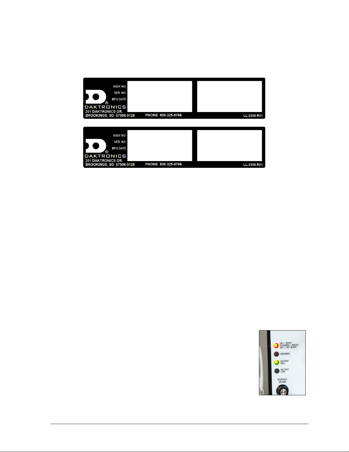
Figure 2: Specifications Labels
Figure 3: Ready to
Start Light
0A-1056-0234
S/N: ####
(DATE) (REVISION)
HS-200
MODEL: DAKT-401-00
12VAC/DC 20WATTS
1.7 AMPS 50/60 HZ
0A-1056-0126
S/N: ####
(DATE) (REVISION)
REMOTE STROBE
MODEL: DAKT-401-00
12VAC/DC 20WATTS
1.7 AMPS 50/60 HZ
1.5 Specification Label
Power specifications as well as serial and model number information can be found on an ID
label on the bottom of the device, similar to those shown in Figure 2.
When calling Daktronics customer service, please have the model number, serial number,
and the date the device became operational available to ensure the request is serviced as
quickly as possible.
1.6 Using the Horn Start
Before Each Session
Follow these basic steps when preparing for a meet:
1. Connect the fully-charged equipment.
2. Verify that all speakers are working.
3. Test the microphone and set volume levels.
4. Test the start signal to the timing system.
5. Verify the strobe light flashes for a start.
6. Verify the HS-200 Horn Start is set to start tone. Refer to Section 2.
7. Verify that the recall signal is set to ON or OFF as desired. Refer to Section 2.5.
8. Verify that Smart Start is turned ON or OFF as desired. Refer to Section 2.5.
Introduction
During Competition
Before starting the next heat, verify the start LED is ON-READY
(Figure 3).
After the Competition
1. Remember to recharge the battery for 24 hours (Figure 15).
2. Turn the power switch to OFF.
3. Store the horn start in a clean, dry place.
Page 10

Page 11
5
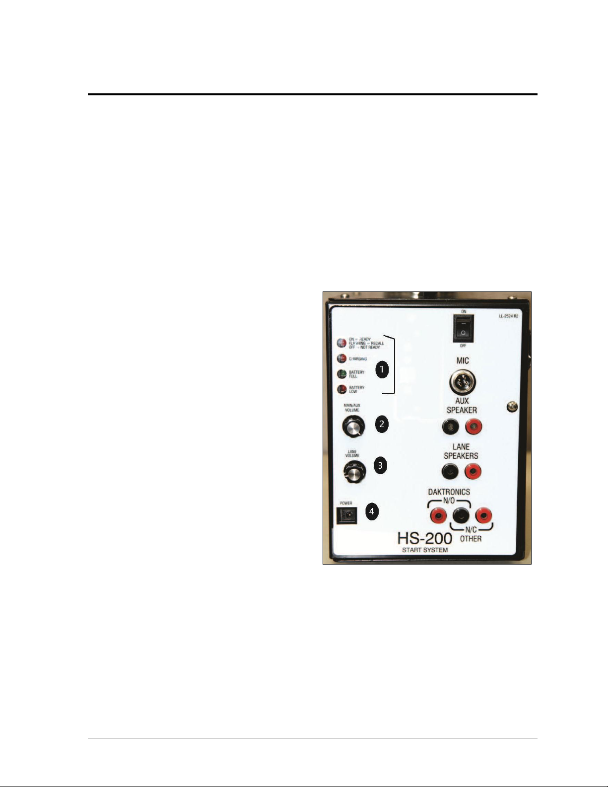
Figure 4: HS-200 Connection Panel
Section 2: System Setup & Operations
2.1 HS-200 Indicators, Switches, Knobs & Connections
The connection panel of the HS-200 horn start (Figure 4) and the HS-200R (Figure 5) is where
all connection, adjustments, and status indicators are located.
The HS-200R is identical to the HS-200 with the addition of the radio receiver for the wireless
belt pack.
1. The group of four LEDs stacked vertically on the upper left corner performs two
functions. Their main function is the one for which they are labeled. The LEDs are
also used to indicate the firmware revision during power-up and to also designate
when the unit is in programming mode. See Section 2.3.
ON-READY LED indicates
when the HS-200 horn start is
ready to start the next race, in
recall mode, or not ready.
CHARGING LED indicates
when the horn start is
connected to main power and
charging the battery. In newer
model horn starts, the
charging light will be on
whether or not the power
switch is turned ON or OFF.
Older models will still be
charging if they are plugged
into main power, but if the
power switch is turned OFF,
the charging LED will not
light up.
BATTERY FULL LED will be
on if the power switch is
turned on, and the battery is
completely charged.
BATTERY LOW LED will be
on if the power switch is turn
ON, and the battery is low.
2. The MAIN/AUX VOLUME control knob sets the volume of the internal speaker built
into the HS-200 horn start plus the volume of the speaker plugged into the jacks
labeled AUX SPEAKER.
3. The LANE VOLUME control knob sets the volume of the speakers plugged into the
jacks labeled LANE SPEAKERS.
4. The POWER connection is for a universal 12 V AC power pack.
System Setup & Operations
Page 12

6
Figure 5: HS-200R Connection Panel
5. ON/OFF switch is the main
power switch. Turn switch to
OFF when the HS-200 horn
start is not being used.
6. The MIC jack is a standard
CB style 4-pin cobra/uniden
microphone connector.
A microphone extension can
be used if it does not exceed
50' (15 m).
7. The AUX SPEAKER jacks
typically connect to the
Auxiliary Speaker cable.
If there are no lane speakers,
plug the Aux Speaker cable
into the LANE SPEAKER
jacks. This will give separate
volume control of the Aux
Speaker and the internal
speaker on the horn start in
addition to each of them
having their own dedicated
amplifier.
8. The LANE SPEAKERS jacks typically connect to the cable from the Lane Speakers.
9. DAKTRONICS N/O and N/C OTHER jacks connect to the timing console start
input. The black jack is the GND tab that the start cable plugs into.
The N/O jack output a Normally Open switch contact—meaning the switch output is
open and closes momentarily to signal the start of the race. The N/C jack output is a
Normally Closed switch contact—meaning the switch output is closed and opens
momentarily to signal the start of the race.
10. These controls and indicators are for the wireless microphone. Refer to Section 3.5
for more information on wireless microphone setup and operation.
System Setup & Operations
Page 13

7
Figure 6: Typical In-Deck Swimming Installation
Figure 7: Typical On-Deck Swimming Installation
Figure 8: HS-200 with Mic
Figure 9: Horn Start with
Internal Speaker
2.2 Start System Setup
Reference Drawing:
HS-200 Horn Start; On-Deck configuration...........................................Drawing A-185695
Refer to Figure 6 (In-Deck) and Figure 7 (On-Deck) for a typical overview when placing the
start system components.
The start system components are shown in Figure 8 - Figure 11. For specific part numbers
and options available, refer to Drawing A-185695 in Appendix A.
System Setup & Operations
Page 14

8
Figure 10: Backstroke
Flagpole Speaker
Figure 11: Lane Speaker
Figure 12: Insert GND Side
to Black Female Jack
Figure 13: Horn Start
Connections
Note: Always install the speakers
tilting down to easily drain and
prevent water from collecting inside.
Note: Always place cables and equipment in areas of minimal
traffic. Cover wires and cables with a mat to prevent accidents.
When plugging in dual banana connectors (Figure 12), the GND
(ground) tab on the plug must line up with the black female jack
for the timing system to work. Remember this when connecting
all dual banana plugs.
Connecting the Horn Start
Connect the cable from the lane speakers into the jacks labeled
LANE SPEAKERS on the HS-200 connection panels.
Connect the cable from the Auxiliary speaker (Backstroke
speaker) into the jacks labeled AUX SPEAKER on the
HS-200 connection panel as shown in Figure 13.
Connect the cable from the OmniSport 2000 start input J12 into
the jacks labeled DAKTRONICS N/O on the HS-2000
connection panel.
Note: Correct connections are crucial for the horn start
to properly function. Improper plugging may cause
damage to the equipment.
If using the HS-200 horn start with an Omega
from the Omega console to the N/C OTHER connectors on the HS-200.
If using the HS-200 horn start with a Colorado Timing System console, connect the
start cable from the CTS console to the N/O connectors on the horn start.
Connect the microphone cable into the jack labeled MIC on the HS-200 connection
panel.
Connect a wallpack power supply from the POWER jack to a 120 VAC outlet.
For complete information on Daktronics timing system setup, refer to Section 2 of the
OmniSport 2000 Timing Console and Pro Software Operations Manual (ED-13312),
available online at www.daktronics.com/manuals.
®
timing console, connect the start cable
System Setup & Operations
Page 15

9
Figure 14: Microphone Buttons
Figure 15: Battery Charging
2.3 Operations
After installation is complete, turn on the power to the unit. Set the volume controls to the
desired levels for the main/auxiliary and lane speakers by adjusting the volume control
knobs along the left side of the unit.
Press and hold the PUSH TO TALK lever (the large
button on the side of the microphone), hold the mic a
few inches away, and speak directly into it. When not
speaking into the microphone, release the PUSH TO
TALK lever (Figure 14).
To activate the horn start system, depress and hold the
PUSH TO TALK lever on the side of the microphone.
While maintaining the pressure on the lever,
momentarily depress the small button on the top of the
microphone. After the start tone has sounded, release
both buttons.
After a race has been started, the RECALL LED flashes for 18 seconds. During this time, the
horn start is in the recall mode. To sound the recall signal, depress the PUSH TO TALK lever
on the side of the microphone and the small button on top of the microphone simultaneously.
The recall signal can be muted. If the recall signal does not sound, or if it sounds when it is
not supposed to, refer to Section 4.
2.4 Battery Operation
With a full charge, the HS-200 battery can
provide up to 15 hours of continuous
operation. When not in use, plug the HS200 wallpack power supply (Daktronics
part # T-1118) into a 120 VAC outlet to
recharge the internal battery (Figure 15).
The internal circuitry monitors the
charging process, so leaving the HS-200
horn start plugged in and charging for
extended periods does not damage the
internal battery. Also, do not run the
battery dead.
The ON/OFF switch on the HS-200
system does NOT need to be turned on to
charge the internal battery. The battery
charging circuitry will be active whenever
the HS-200 wallpack power supply is
plugged into the wall outlet.
When the HS-200 wallpack power supply is plugged in, the CHARGING LED will give the
battery-charging status. If the CHARGING LED is off (or flashing) and the BATTERY FULL
LED is on, the battery is fully charged.
System Setup & Operations
Page 16

10
When the HS-200 system is being powered by the battery and is not plugged into the wall,
the BATTERY FULL and BATTERY LOW LEDs show battery status. The green BATTERY
FULL LED indicates when the battery voltage level is fine for operation. The red BATTERY
LOW LED indicates the battery voltage level is half drained and should be charged soon.
Should the red BATTERY LOW LED begin flashing, the HS-200 unit has 10 minutes of
battery power remaining and will automatically shut down after this period has expired. At
this time, the horn start should be charged immediately. Once the charger is connected to a
120 VAC outlet, the HS-200 system will operate normally.
For information about possible problems with battery charging, please refer to Section 4.
2.5 Horn Start Settings
Enable or Disable Recall On
1. Plug the handheld microphone directly into the MIC jack on the HS-200 horn start.
2. To access the setup mode, turn the power switch to ON. Immediately after the
BATTERY FULL and BATTERY LOW LEDs flash, press the PUSH TO TALK lever
three times.
3. The four LED indicators on the horn start will flash and the speaker will sound a
warbling tone when the Recall On setting is active. If that setting is not active, then
no sound will come from the speaker and the four LED indicators will flash.
4. To change the setting, press the PUSH TO TALK button once. This will enable or
disable the setting.
5. To save the current setting, press and hold the PUSH TO TALK button while
pressing the top button twice. The LEDs should stop flashing. The HS-200 horn start
is now configured for the selected recall setting.
Configure Start Sound
Select between two different swimming tones or a gun shot.
1. Plug the handheld microphone directly into the MIC jack on the HS-200.
2. To access the setup mode, turn the power switch to ON. Immediately after the
BATTERY FULL and BATTERY LOW LEDs flash, press the PUSH TO TALK lever
four times.
3. The four LED indicators on the horn start will flash and the speaker will sound the
current setting. This sound will be either the tone or the gunshot.
4. To change the setting, press the PUSH TO TALK button. Every time that button is
pushed, it will move to a different setting.
5. To save the current setting, press and hold the PUSH TO TALK button while
pressing the top button twice. The LEDs should stop flashing.
System Setup & Operations
Page 17

11
Enable Practice Mode
Practice mode is available on 0A-1056-0234/0235 models only. Refer to Section 3.2.
1. Plug the handheld microphone directly into the MIC jack on the HS-200 horn start.
2. Turn the power switch on and immediately press and hold both the PUSH TO
TALK and top buttons.
3. The horn start speaker will sound off a Start tone. The HS-200 horn start is now in
Practice Mode.
4. Cycling the power switch of the HS-200 to will set the horn start back to normal.
Enable or Disable Smart Start
Smart Start is available on 0A-1056-0234/0235 models only.
1. Plug the handheld microphone directly into the MIC jack on the HS-200 horn start.
2. To access the setup mode, turn the power switch to ON. Immediately after the
BATTERY FULL and BATTERY LOW LEDs flash, press the PUSH TO TALK lever
five times.
3. The three lower LED indicators on the horn start will flash. The READY/RECALL
LED will either be ON or OFF.
4. To change the setting, press the PUSH TO TALK button once. The
READY/RECALL LED will change to ON or OFF.
If the READY/RECALL LED is ON the Smart Start is activated.
If the READY/RECALL LED is OFF the Smart Start is deactivated (default).
5. To save the current setting, press and hold the PUSH TO TALK button while
pressing the top button twice. The LEDs should stop flashing. The HS-200 is now
configured with the selected Smart Start setting.
2.6 Equipment Storage
The HS-200 unit and speakers should be stored in a cool, dry place, away from the pool
environment. Coil and store all cables away from the pool.
The charging circuit is designed so the battery can be charged for extended periods; however,
it is not required that the HS-200 horn start be connected to the wall outlet during the offseason. Before storage, plug the HS-200 horn start into the wall outlet for 24 hours to fully
charge the battery. Allow 24 hours of recharge time after the HS-200 horn start has been
taken out of storage as well. It is important to ensure the horn start’s battery is not drained.
System Setup & Operations
Page 18

Page 19

13
Figure 16: Flagpole Bracket
Section 3: Features & Accessories
This section describes the accessories that are available with the HS-200 horn start.
3.1 Smart Start
Note: This feature is available on 0A-1056-0234/0235 models only.
The latest HS-200 horn start has the capability to detect a connection from the timer console.
If the horn start is connected to an OmniSport 2000 timing console, the Smart Start will
sense the timer via the dual banana plug extension cable plugged into the N/O or N/C
OTHER input.
When activated (see Section 2.5), the Smart Start feature will allow normal use of the horn
start microphone but will not allow a Start tone and Strobe activation unless the HS-200 is
connected to the timing console and the console is ready for the next race. Should the timing
console not have a ready status feature, then the Smart Start will function based on cable
connection only.
If a timing console is ready and properly connected, the READY/RECALL LED will be on
and not flashing. It will take a couple of seconds to initialize. If no timing console is present
and/or the cable connecting the HS-200 and console is damaged, unplugged, or plugged in
backwards (black into red), the READY/RECALL LED will be OFF.
3.2 Practice Mode
Note: This feature is available on 0A-1056-0234/0235 models only.
Setting the HS-200 into Practice Mode (see Section 2.5) changes the delay time between
consecutive starts to three seconds between beeps compared to the default delay time of
eighteen seconds. Cycling the power on the horn start will deactivate Practice Mode.
Note: When in Practice Mode, the strobe will not flash until after ten seconds have elapsed
between strobes. Also, the Smart Start feature is disabled while in Practice Mode.
It is NOT recommended that Practice Mode be used for timed competitions.
3.3 Backstroke Flagpole Bracket
The Backstroke Flagpole Bracket (Figure 16) allows the
horn start to be mounted to the backstroke flagpole. When
pool deck space is limited, this eliminates the clutter of a
podium or tri-pod on the deck and the possibility of the
unit being knocked into the pool. The backstroke flagpole
is also a good position for the horn start because sound is
distributed evenly across the lanes.
Features & Accessories
Page 20

14
Figure 17: Remove Screws
Figure 18: Attach Bracket
Figure 19: Remote Strobe
Attaching the Horn Start to Flagpole
1. Use a #2 Phillips screw
driver and remove topmiddle screw and the two
right-rear screws identified
in Figure 17.
2. Mount the backstroke
flagpole bracket as
illustrated in Figure 18.
3. Re-install the three screws
removed in step 1.
4. Use both locking straps to securely fasten the unit to the flagpole.
3.4 Remote Strobe
Mounting Bracket & Strap
A mounting bracket and strap are included
with the remote strobe for mounting to a
backstroke flagpole or to a start block.
The remote strobe also has rubber feet for
setting on any flat surface.
Battery Operation
The HS-200 remote strobe includes an internal
12 VDC battery that provides up to 15 hours of
continuous use. Using the remote strobe on
battery power requires one end of a start
extension cable with the dual banana plug to be
plugged into the UNIVERSAL START INPUT (Figure 19).
The other end of the cable should plug into either the N/O or N/C jack on the HS-200. If the
HS-200 is also connected to the OmniSport timer, the remote strobe cable will piggyback onto
the timer output cable. Use N/O start output when using Daktronics or CTS timers. Use N/C
when using Omega timers.
The remote strobe turns on automatically when it receives a start signal from the start unit.
The green PWR ON LED will light and the internal buzzer will sound.
The remote strobe requires a 15-second period between start signals to produce a flash.
Any start signal received within 15 seconds of the previous start signal will sound the
internal buzzer but may not flash the strobe. To simulate a start with a backup push button,
connect the button into the start input and press the button until the remote strobe flashes.
In order to conserve battery life, the remote strobe will turn itself off after one hour with no
use. To turn the strobe back on, connect it to the starting device and send a start signal.
Multiple start signals may be needed in order to charge the strobe. Apply start signals until
the strobe flashes.
When the internal battery reaches a low level, the red BATTERY LOW LED will light for
approximately 30 seconds and the remote strobe will turn off. Any start signal received after
the internal battery is low will light the BATTERY LOW LED momentarily.
Features & Accessories
Page 21

15
Figure 20: Wireless Microphone
AC Power Operation & Recharging
Note: For safety reasons, when using the remote strobe near water, use battery power for
device operation to minimize the risk of electrical shock.
The HS-200 remote strobe operates the same way whether using AC power or battery power.
The remote strobe includes a circuit that will recharge the internal battery when the wallpack
power supply is connected to a 120 VAC outlet. When the remote strobe is connected to AC
power, the green PWR ON LED lights up and the strobe is ready for use. The internal battery
will recharge in approximately three to four hours. Due to internal battery monitoring
circuitry, the remote strobe can be plugged into the wall for extended periods without
overcharging. The amber BAT CHRG LED is illuminated when the internal battery is
being charged.
Remote Strobe for Training Purposes
To use the remote strobe during training sessions, instead of connecting it to the HS-200 start
unit, a backup push button can be connected into the start input. When the backup push
button is pressed, the remote strobe will operate the same way it did when connected to the
start unit.
3.5 Wireless Microphone Belt Pack
The HS-200R wireless microphone belt pack is an accessory that allows the starter
to direct and start events without a wired connection to the horn start unit. The HS-200R
system is equipped with an internal radio module. A standard HS-200 system can be
retrofitted with an internal radio module to enable the use of the wireless microphone. With
the wireless microphone option, two microphones can be used; one wired and one wireless.
The same handheld microphone that plugs into the HS-200 directly, or via microphone
extension cords, is used with the wireless microphone belt pack. For operation of the
handheld microphone refer to Section 2.3.
Note: When the PUSH TO TALK lever is activated, a small “pop” sound occurs.
Using the Wireless Microphone Option
1. Verify that the belt pack has good batteries.
2. Set the Channel.
3. Plug the handheld microphone into the belt pack.
4. Clip the lanyard (neck strap) to the handheld
microphone as demonstrated in Figure 20.
5. Clip on belt pack and hang the lanyard from neck.
6. Proceed with starting events.
The decimal point on the CHANNEL # LCD illuminates when the microphone PUSH TO
TALK lever is pressed, indicating that the wireless microphone belt pack is transmitting.
Features & Accessories
Page 22

16
Set Channel Button
The wireless microphone belt pack and the HS-200R unit both include a SET CHANNEL
button to select the radio channel used for the start signal. Pressing the SET CHANNEL
button once on the wireless microphone belt pack shows the current transmit channel on the
CHANNEL # LCD. Pressing the button while the channel number is displayed moves to the
next channel. As with the wireless microphone belt pack, pressing the SET CHANNEL
button on the HS-200R unit changes the current radio channel; the current channel is always
displayed on the CHANNEL LCD. Channels 0-7 are available for use.
The wireless microphone belt pack SET CHANNEL button can control the HS-200R main
unit channel selection automatically once they have been set to the same channel. To do this,
cycle through the channels on the wireless microphone belt pack until the channel on the belt
pack matches the one on the main unit. Once set to the same channel, the units will be
synchronized. To ensure they are synchronized, press the SET CHANNEL button on the
wireless microphone belt pack. If the channel on the HS-200R main unit changes with the
channels shown on the belt pack, the synchronization was successful.
Wireless Belt Pack Batteries
The wireless microphone belt pack uses two AA batteries for operation (included). To replace
the batteries, remove the cover on the back of the wireless microphone belt pack. Always
keep spare batteries on hand for each meet.
The wireless microphone operates for approximately 30 hours under meet conditions on one
set of batteries. Though the wireless microphone belt pack uses a miniscule amount of battery
power when not in use, the batteries should be removed after every meet to prevent damage
from battery acid leakage. Properly dispose any dead batteries.
The CHANNEL # LCD shows an “L” when the batteries are low. If an “L” appears when the
PUSH TO TALK lever is pressed, replace the batteries in the unit as soon as possible.
HS-200R Internal Radio Module General Operation
Set Channel Button
Press the SET CHANNEL button on the HS-200R unit to change the current channel.
This channel will also need to be selected on the wireless microphone belt pack. The channel
on the HS-200R system should change automatically when a new channel is selected on the
wireless microphone belt pack.
Carrier LED
The amber CARRIER LED on the HS-200R unit illuminates when radio data (or noise) is
present in the selected channel. Before the start of a meet, watch this LED for any activity;
it should only come on when the wireless microphone is activated. If the amber LED comes
on or flickers when the wireless microphone is not activated, there is radio interference.
Select a channel that has a minimum amount of interference for best operation. On start-up,
the HS-200R unit will default to the last channel used before shutdown.
Receive LED
The green LED on the HS-200R unit illuminates when a valid radio transmission has been
received from the wireless microphone. This LED should be on whenever the microphone
PUSH TO TALK lever is pressed.
Features & Accessories
Page 23

17
Section 4: Troubleshooting
This section gives detailed information about troubleshooting some of the situations that the HS200/HS-200R system operator may experience. If the actions listed in this section are unable to be
performed or do not solve a particular issue, contact a local representative or Daktronics Customer
Service Department for assistance (refer to Section 5).
4.1 Troubleshooting Tips
Aux or Lane speaker is not working
Connect the correct speaker directly to the appropriate HS-200/HS-200R jack without any
extension cables. If the speaker still does not work, the speaker is faulty and must be
replaced. If the speaker begins to work, the cable that connects to that speaker is at fault and
must be repaired or replaced.
The microphone is not working
Make sure the power is on and that the volume controls are up high enough to be heard.
Press the microphone PUSH TO TALK lever and Start/Recall buttons simultaneously to
attempt a start. Disconnect and reconnect the microphone to ensure a good connection.
If there is a microphone extension cable being used, unplug it and the plug the microphone
into the horn start directly. If either the start function or microphone still does not work,
the microphone must be replaced.
The strobe light does not work
Make sure the READY/RECALL LED is lit and steady. If the BATTERY LOW LED is on,
plug the HS-200/HS-200R into the wall outlet and retry. Send up to 4-6 start signals into the
remote strobe. The capacitor must be energized first to work properly. If it still does not
work, the strobe light must be replaced.
Noise bursts when using the wireless microphone
There may be another piece of equipment interfering with the wireless microphone. Select
each channel individually and watch the amber CARRIER LED on the HS-200R. Look for a
channel where the amber LED stays off when the wireless microphone is not in operation.
If all channels are noisy, attempt to determine which equipment is interfering by turning off
other electronic equipment in the area. If the interference cannot be eliminated, a wired
microphone must be used.
Microphone works but the horn start will not Start/Strobe
Ensure that the horn start Smart Start setting is set to the desired mode of operation (see
Section 2.5). If the Smart Start is enabled, ensure that the horn start unit is properly
connected to a timing console such as an OmniSport 2000 controller, and that the cable is not
damaged. Alternately, turn off the Smart Start setting.
The recall tone does not sound
Verify the recall function is enabled on the HS-200/HS-200R unit. Refer to Section 2.5.
Troubleshooting
Page 24

18
Part
Order Number
HS-200 horn start unit
0A-1056-0234
Handheld dual switch microphone with coiled cord
0A-1056-0173
Microphone extension, 15' (4.5 m)
0A-1056-0122
Wallpack power supply
T-1118
OmniSport® timer output cable, 30' (9.1 m)
W-1425
Part
Order Number
Microphone extension, 15' (4.5 m)
0A-1056-0122
Wireless microphone belt pack
0A-1056-0134
Handheld dual switch microphone with coiled cord
0A-1056-0173
HS-200R horn start unit
0A-1056-0235
Wallpack power supply
T-1118
OmniSport Timer output cable, 30' (9.1 m)
W-1425
The HS-200/HS-200R will not run with battery power
When AC power is connected, the CHARGING LED is flashing, and the BATTERY FULL
LED is lit, the internal fuse may be blown. A 2.5 amp AGC fuse protects the internal battery
from short circuit. To replace this fuse, disconnect the HS-200/HS-200R unit from the wall
outlet, and turn the power switch off. Open the enclosure cover by removing the 10 screws
on the top, bottom, and sides. Once the enclosure is open, disconnect the battery by
unplugging the 2-pin connector near the bottom center of the printed circuit board. Remove
the fuse next to this connector and replace with an AGC 2.5 amp fuse. Reconnect the battery
and assemble the enclosure cover.
Note: The fuse has been removed from models 0A-1056-0234/0235.
If the CHARGING LED is off and the BATTERY LOW LED is lit, the battery may no longer
work or may have been severely damaged due to long periods of usage when the battery was
underpowered. Plug the horn start into the wall outlet for 24 hours. If the same problem
occurs, the battery should be replaced.
4.2 Replacement Parts
HS-200 Equipment (0A-1056-0116)
HS-200R Equipment (0A-1056-0136)
Troubleshooting
Page 25

19
Part
Order Number
Speaker Extension Cord 10' (3 m)
0A-1056-0081
Microphone Extension 50' (15 m)
0A-1056-0123
Remote Strobe with buzzer
0A-1056-0126
Flag Pole Mounting Bracket, HS-200
0A-1056-0129
Wireless Microphone Update, HS-200 with wired Microphone
0A-1056-0135
Speaker Extension Cord 125' (38 m)
0A-1056-0154
Speaker Extension Cord 200' (61 m)
0A-1056-0165
Cable; 30’ (9.1 m) Adapter for Horn Start to Lynx
0A-1125-0001
Start Extension on Reel 500' (152 m)
Backstroke Flag Pole Speaker with Mounting Bracket
0F-1056-0030
Lane Speaker
0F-1056-0036
Speaker Extension Cord 30' (9.1 m)
0F-1056-0047
Tripod Stand, Requires Flag Pole Mounting Bracket (not included)
A-1580
Power Supply, 240 V AC, HS-200
A-1755
Starter Extension Cable; 10' (3 m)
W-1426
Starter Extension Cable; 125' (38 m)
W-1517
Starter Extension Cable; 200' (61 m)
W-1518
Optional Equipment
Troubleshooting
Page 26

Page 27

21
Market Description
Customer Service
Number
Schools (including community/junior colleges), religious
organizations, municipal clubs and community centers
877-605-1115
Universities and professional sporting events, live events
for auditoriums and arenas
866-343-6018
Section 5: Daktronics Exchange and Repair &
Return Programs
5.1 Exchange Program
The Daktronics Exchange Program is a service for quickly replacing key components in need
of repair. If a component fails, Daktronics sends a replacement part to the customer who, in
turn, returns the failed component to Daktronics. This decreases equipment downtime.
Customers who follow the program guidelines explained below will receive this service.
Before Contacting Daktronics
Identify these important part numbers:
Serial Number: __________________________________________________
Job/Contract Number: ___________________________________________
Date Installed: __________________________________________________
Daktronics Customer ID Number: _________________________________
To participate in the Exchange Program, follow these steps.
1. Call Daktronics Customer Service.
2. If the replacement part fixes the problem, send in the problem part being replaced.
a. Package the old part in the same shipping materials in which the replacement
part arrived.
b. Fill out and attach the enclosed UPS shipping document.
c. Ship the part to Daktronics.
3. The defective or unused parts must be returned to Daktronics within 5 weeks of
initial order shipment.
If any part is not returned within five (5) weeks, a non-refundable invoice will be
presented to the customer for the costs of replenishing the exchange parts inventory
with a new part.
Daktronics reserves the right to refuse parts that have been damaged due to acts of
nature or causes other than normal wear and tear.
Daktronics Exchange and Repair & Return Programs
Page 28

22
5.2 Repair & Return Program
For items not subject to exchange, Daktronics offers a Repair & Return Program. To send a
part for repair, follow these steps:
1. Call or fax Daktronics Customer Service:
Refer to the appropriate market number in the chart listed on the previous page.
Fax: 605-697-4444
2. Receive a case number before shipping.
This expedites repair of the part.
3. Package and pad the item carefully to prevent damage during shipment.
Electronic components, such as printed circuit boards, should be placed in an
antistatic bag before boxing. Daktronics does not recommend using packing
‘peanuts’ when shipping.
4. Enclose:
name
address
phone number
the case number
a clear description of symptoms
Shipping Address
Daktronics Customer Service
[Case #]
201 Daktronics Drive, Dock E
Brookings, SD 57006
5.3 Daktronics Warranty and Limitation of Liability
The Daktronics Warranty and Limitation of Liability is located in Appendix B. The Warranty
is independent of Extended Service agreements and is the authority in matters of service,
repair, and display operation.
Daktronics Exchange and Repair & Return Programs
Page 29

23
Appendix A: Reference Drawings
Drawing Title Drawing Number
HS-200 Horn Start; On-Deck Configuration ............................................................................. A-185695
Reference Drawings
Page 30

Page 31

Page 32

Page 33

25
Appendix B: Daktronics Warranty and Limitation
of Liability
Daktronics Warranty and Limitation of Liability
Page 34

Page 35

Copyright © Daktronics, Inc. SL-02374 Rev 10 02-Mar-2009 Page 1 of 2
DAKTRONICS
WARRANTY AND LIMITATION OF LIABILITY
This Warranty and Limitation of Liability (the “Warranty”) sets forth the warranty provided by Daktronics with respect to the Equipment. By
accepting delivery of the Equipment, Purchaser agrees to be bound by and accept these terms and conditions. All defined terms within
the Warranty shall have the same meaning and definition as provided elsewhere in the Agreement.
DAKTRONICS WILL ONLY BE OBLIGATED TO HONOR THE WARRANTY SET FORTH IN THESE TERMS AND CONDITIONS UPON RECEIPT OF FULL
PAYMENT FOR THE EQUIPMENT.
1. Warranty Coverage
2. Exclusion from Warranty Coverage
A. Daktronics warrants to the original end-user that the Equipment will be free from Defects (as defined below) in materials and
workmanship for a period of one (1) year (the “Warranty Period”). The warranty period shall commence on the earlier of: (i) four
weeks from the date that the equipment leaves Daktronics’ facility; or (ii) Substantial Completion as defined herein. The warranty
period shall expire on the first anniversary of the commencement date.
“Substantial Completion” means the operational availability of the Equipment to the Purchaser in accordance with the
Equipment’s specifications, without regard to punch-list items, or other non-substantial items which do not affect the operation of
the Equipment.
B. Daktronics’ obligation under this Warranty is limited to, at Daktronics’ option, replacing or repairing, any Equipment or part
thereof that is found by Daktronics not to conform to the Equipment’s specifications. Unless otherwise directed by Daktronics,
any defective part or component shall be returned to Daktronics for repair or replacement. Daktronics may, at its option,
provide on-site warranty service. Daktronics shall have a reasonable period of time to make such replacements or repairs and
all labor associated therewith shall be performed during regular working hours. Regular working hours are Monday through
Friday between 8:00 a.m. and 5:00 p.m. at the location where labor is performed, excluding any holidays observed by either
Purchaser or Daktronics.
C. Daktronics shall pay ground transportation charges for the return of any defective component of the Equipment. If returned
Equipment is repaired or replaced under the terms of this warranty, Daktronics will prepay ground transportation charges back to
Purchaser; otherwise, Purchaser shall pay transportation charges to return the Equipment back to the Purchaser. All returns must
be pre-approved by Daktronics before shipment. Daktronics shall not be obligated to pay freight for any unapproved return.
Purchaser shall pay any upgraded or expedited transportation charges.
D. Any replacement parts or Equipment will be new or serviceably used, comparable in function and performance to the
original part or Equipment, and warranted for the remainder of the Warranty Period. Purchasing additional parts or Equipment
from the Seller does not extend this Warranty Period.
E. Defects shall be defined as follows. With regard to the Equipment (excepting LEDs), a “Defect” shall refer to a material
variance from the design specifications that prohibit the Equipment from operating for its intended use. With respect to LEDs,
“Defects” are defined as LED pixels that cease to emit light. The limited warranty provided by Daktronics does not impose any
duty or liability upon Daktronics for partial LED pixel degradation. Nor does the limited warranty provide for the replacement or
installation of communication methods including but not limited to, wire, fiber optic cable, conduit, trenching, or for the purpose
of overcoming local site interference radio equipment substitutions.
THIS LIMITED WARRANTY IS THE ONLY WARRANTY APPLICABLE TO THE EQUIPMENT AND REPLACES ALL OTHER WARRANTIES OR
CONDITIONS, EXPRESS OR IMPLIED, INCLUDING, BUT NOT LIMITED TO, THE IMPLIED WARRANTIES OR CONDITIONS OF
MERCHANTABILITY AND FITNESS FOR A PARTICULAR PURPOSE. SPECIFICALLY, EXCEPT AS PROVIDED HEREIN, THE SELLER
UNDERTAKES NO RESPONSIBILITY FOR THE QUALITY OF THE EQUIPMENT OR THAT THE EQUIPMENT WILL BE FIT FOR ANY PARTICULAR
PURPOSE FOR WHICH PURCHASER MAY BE BUYING THE EQUIPMENT. ANY IMPLIED WARRANTY IS LIMITED IN DURATION TO THE
WARRANTY PERIOD. NO ORAL OR WRITTEN INFORMATION, OR ADVICE GIVEN BY THE COMPANY, ITS AGENTS OR EMPLOYEES,
SHALL CREATE A WARRANTY OR IN ANY WAY INCREASE THE SCOPE OF THIS LIMITED WARRANTY.
THIS LIMITED WARRANTY IS NOT TRANSFERABLE.
The limited warranty provided by Daktronics does not impose any duty or liability upon Daktronics for:
A Any damage occurring, at any time, during shipment of Equipment unless otherwise provided for in the Agreement. When
returning Equipment to Daktronics for repair or replacement, Purchaser assumes all risk of loss or damage, and agrees to use
any shipping containers that might be provided by Daktronics and to ship the Equipment in the manner prescribed by
Daktronics;
B. Any damage caused by the unauthorized adjustment, repair or service of the Equipment by anyone other than personnel of
Daktronics or its authorized repair agents;
Page 36

Copyright © Daktronics, Inc. SL-02374 Rev 10 02-Mar-2009 Page 2 of 2
C. Damage caused by the failure to provide a continuously suitable environment, including, but not limited to: (i) neglect or
misuse, (ii) a failure or sudden surge of electrical power, (iii) improper air conditioning or humidity control, or (iv) any other cause
other than ordinary use;
D. Damage caused by fire, flood, earthquake, water, wind, lightning or other natural disaster, strike, inability to obtain materials
or utilities, war, terrorism, civil disturbance or any other cause beyond Daktronics’ reasonable control;
E. Failure to adjust, repair or replace any item of Equipment if it would be impractical for Daktronics personnel to do so because
of connection of the Equipment by mechanical or electrical means to another device not supplied by Daktronics, or the
existence of general environmental conditions at the site that pose a danger to Daktronics personnel;
F. Any statements made about the product by salesmen, dealers, distributors or agents, unless such statements are in a written
document signed by an officer of Daktronics. Such statements as are not included in a signed writing do not constitute
warranties, shall not be relied upon by Purchaser and are not part of the contract of sale;
G. Any damage arising from the use of Daktronics products in any application other than the commercial and industrial
applications for which they are intended, unless, upon request, such use is specifically approved in writing by Daktronics; or
H. Any performance of preventive maintenance.
3. Limitation of Liability
4. Assignment of Rights
5. Dispute Resolution
6. Governing Law
7. Availability of Extended Service Agreement
Daktronics shall be under no obligation to furnish continued service under this Warranty if alterations are made to the Equipment
without the prior written approval of Daktronics.
It is specifically agreed that the price of the Equipment is based upon the following limitation of liability. In no event shall
Daktronics (including its subsidiaries, affiliates, officers, directors, employees, or agents) be liable for any special, consequential,
incidental or exemplary damages arising out of or in any way connected with the Equipment or otherwise, including but not
limited to damages for lost profits, cost of substitute or replacement equipment, down time, lost data, injury to property or any
damages or sums paid by Purchaser to third parties, even if Daktronics has been advised of the possibility of such damages. The
foregoing limitation of liability shall apply whether any claim is based upon principles of contract, tort or statutory duty, principles
of indemnity or contribution, or otherwise.
In no event shall Daktronics be liable to Purchaser or any other party for loss, damage, or injury of any kind or nature arising out of
or in connection with this Warranty in excess of the purchase price of the Equipment actually delivered to and paid for by the
Purchaser. The Purchaser’s remedy in any dispute under this Warranty shall be ultimately limited to the Purchase Price of the
Equipment to the extent the Purchase Price has been paid.
The Warranty contained herein extends only to the original end-user (which may be the Purchaser) of the Equipment and no
attempt to extend the Warranty to any subsequent user-transferee of the Equipment shall be valid or enforceable without the
express written consent of Daktronics.
Any dispute between the parties will be resolved exclusively and finally by arbitration administered by the American Arbitration
Association (“AAA”) and conducted under its rules, except as otherwise provided below. The arbitration will be conducted
before a single arbitrator. The arbitration shall be held in Brookings, South Dakota. Any decision rendered in such arbitration
proceedings will be final and binding on each of the parties, and judgment may be entered thereon in any court of competent
jurisdiction. This arbitration agreement is made pursuant to a transaction involving interstate commerce, and shall be governed
by the Federal Arbitration Act.
The rights and obligations of the parties under this warranty shall not be governed by the provisions of the United Nations
Convention on Contracts for the International Sales of Goods of 1980. Both parties consent to the application of the laws of the
State of South Dakota to govern, interpret, and enforce all of Purchaser and Daktronics rights, duties, and obligations arising
from, or relating in any manner to, the subject matter of this Warranty, without regard to conflict of law principles.
For Purchaser’s protection, in addition to that afforded by the warranties set forth herein, Purchaser may purchase extended
warranty services to cover the Equipment. The Extended Service Agreement, available from Daktronics, provides for electronic
parts repair and/or on-site labor for an extended period from the date of expiration of this warranty. Alternatively, an Extended
Service Agreement may be purchased in conjunction with this warranty for extended additional services. For further information,
contact Daktronics Customer Service at 1-800-DAKTRONics (1-800-325-8766).
 Loading...