

Page 1
HOIST SYSTEM
INSTALLATION
GUIDE
Page 2

HOIST INSTALLATION MANUAL
Daktronics Automated Theatre Rigging System
Manufacturer contact
7200 Rawson Road
Victor, New York 14564
tel 866-486.7835 585-924-5000
fax 585-924-0545
email sales@daktronics.com
www.daktronics.com/rigging
Page 3

TABLE OF CONTENTS
Introduction
Warning and Compliance with Regulations ......................................2
Tool List and Hoist Overview ...........................................................3
Mechanical Installation
When the Hoists Arrive
Unloading Vortek Hoists ............................................................4
Proper Staging of Vortek Units ....................................................5
Uncrating Vortek Hoists .............................................................6
Using the Installation Blocks ............................................................6
Using Hoist Lifting Clips and Installing Backbone Stiffeners .................7
Attaching the Backbone Stiffeners and Installing the Hoist ...................8
Completing the Vortek Hoist Installation ...........................................9
Installing Vortek Loft Blocks ............................................................10
Routing the Lift Lines ....................................................................11
Terminating Wire Rope Cables ......................................................12
TABLE OF CONTENTS
1
Page 4
INTRODUCTION
This guide assists with the most common Daktronics installations and scenarios showing basic mechanical
layouts.
Each installation will have its own layout and drawings as specifi ed by the Architect and Theater Consultant
that works best for the theater involved. Refer to the drawings for specifi c information that may be needed.
If any questions arise, please contact Daktronics at:
585-924-5000
8am to 5pm, Monday through Friday EST/EDT
When calling please specify whether the question refers to an electrical or mechanical rigging issue.
Electrical Safety—General Warning
All Warning notes contained in this manual indicate information that may endanger personnel.
WARNING
WARNING
The voltages used in the motor drive and master control panels can cause severe electrical
shock and/or burns. Extreme care is necessary at all times when working with the motor
drives. Only authorized personnel should carry out any installation, commissioning, or
maintenance of the electrical systems. All drive systems have been tuned at the factory
and will not require any additional alteration or adjustment by the owner’s personnel
unless specifically authorized by a Daktronics representative.
Before working on any of the Vortek hoists, the main electrical disconnect must be
turned off and locked out according to OSHA regulations 29 CFR 1910.147.
Compliance with Regulations
The Vortek system complies with the relevant European directives required for the CE mark, including:
98/37/EC: Machinery Directive
73/23/EEC: Low Voltage Directive
89/336/EEC: Electromagnetic Compatibility
Independent reviews/tests in support of above compliance
EN55022 / Class A Radiated and Conducted Emissions
EN61000-4-2 / Electrostatic Discharge
EN61000-4-6 / Conducted Susceptibility
EN60950, 60204 / Safety Review
Standard products are ETL listed to the following UL Standards
UL508A - UL Standard For Industrial Control Panels
UL1340 - UL Standard For Hoists.
2
Page 5
Vortek® Hoist Installation Tool List
1. 9/16" Combination Wrench
2. 3/4" Combination Wrench
3. 3/8" drive 7/16" Socket
4. 3/8" drive 1/2" Socket
5. 3/8" drive 9/16" Deep Well Socket
6. 1/2" drive 3/4" Deep Well Socket
7. 3/8" drive torque wrench
8. 3/8" drive ratchet
9. 1/2" drive ratchet
10. 18" long 3/8" drive “wobble” extension or universal
11. 1/4" Allen Wrench
12. 3/32" Allen Wrench
13. Cordless drill with 3/8" drive attachment
14. Tape Measure
15. Metal Banding Cutter
16. Nicopress Tool
17. Cable Cutter
18. Electrical Tape
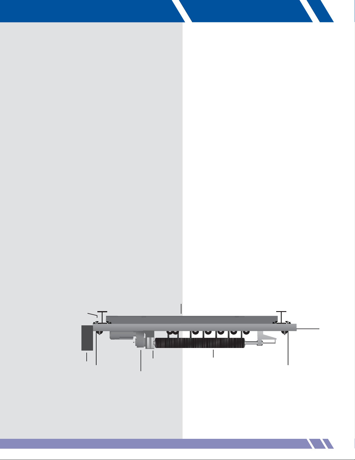
Basic Hoist Components
Beam clamps
ˇ
MOTOR
END
ˆ
Power panel
Cable drop
ˆ
Gearbox/Motor
Backbone stiffeners
ˇ
ˆ
Vortek load brake
ˆ
Drum
TAIL END
Cable drop
SAFETY INFORMATION
INTRODUCTION
Cables
out end
3
Page 6

MECHANICAL INSTALLATION
Unloading Vortek Hoists
When the truck(s) arrives with the Vortek hoists,
unloading and getting them situated for either
storage or immediate installation will make
the installation process much easier.
Each Vortek hoist crate has a packing sheet
(Figure 1) attached that specifi es what type of
unit it is and the quantities supplied. Be sure to note
the accessory box shipped together with the crates,
typically one or more per project.
Each crated Vortek hoist weighs approximately 1100
lbs. (500 kg) There are only two places where the
Vortek crates can be lifted with a forklift.
The fi rst lifting point is from the end (Figure 2) with
a forklift that has fork tines that are at least 41" long,
a maximum of 8-1/2" wide and 2" thick to use this
location.
Insert the forks completely into the slot. Raise the
forks and the rack to lift the crate.
The second lifting point is from the side (Figure 3).
When using this location, spread the forks as wide
as possible. Either side can be used to lift the crates.
The Vortek hoists are not balanced at
center so care must be taken when
moving the units.
Each Vortek crate will be labeled with the model
number and/or set number (Figure 4). Organizing
the hoists as they are unloaded may help during
installation.
Figure 1: Packing sheet and accessory box
Figure 2: Lift end of crate
Figure 3: Lift center of crate
Figure 4: Crate label
4
Page 7

Figure 5: Typical hoist layout
Figure 6: Nameplate
Figure 7: Model number label
Follow the layout plan in order to place the crates
in the right position. Figure 5 shows one possible
way the Vortek hoists might be installed.
The layout, nameplate and label on the side of the
crate identify model number placement within the
installation.
Once out of the crate, Vortek Classic hoists are
virtually indistinguishable from each other except
for the nameplate on top of the electronics cabinet
(Figure 6).
Each hoist with Pro Series or M Series controller
has a pre-programmed network address and a
set number that is attached to the side of the hoist
(Figure 7). Please refer to the set plan layout for
the proper location.
If the wrong type of unit is installed in a
position that is specifi ed for another, it will
have to be uninstalled and moved to the
correct position.
INSTALLATION
5
Page 8

Uncrating the Vortek Hoist
The wooden shipping container is a two-piece
unit. The top portion that consists of the top,
ends, and sides are one unit (Figure 8). There
is a bottom skid that the Vortek hoist rides on.
Simply clip the banding and lift the top portion
of the crate off for easy unpacking.
Please return the shipping crates
to Daktronics for re-use.
Cut the remaining banding and remove the
poly sheeting from the hoist (
Figure 9). There
will be either two backbone stiffeners loosely
attached on top of the unit or two extra beam
clamp assemblies pre-installed at the factory.
This will depend on a two or three-beam
installation.
Using the Installation Blocks
Figure 8: Lift crate top off bottom skid
Daktronics offers optional installation blocks
that will assist in lifting and mounting the Vortek
hoists. These may be purchased from Daktronics
if needed. Figure 10 illustrates mounting of
the installation blocks.
The installation blocks go on the offstage side
and the onstage side of the steel beams. This
allows the space for the backbone stiffeners to
be placed into the backbone channel.
The installation blocks require a minimum of 9"
of adjacent space on the steel beams as the
hoist is lifted into place (Figure 11).
Figure 9: Cut banding and remove sheeting
Figure 10: Installation block with pivoting sheave and fixed sheave
Figure 11: Maintain spacing between steel beams
6
Page 9

Figure 12: Set clip into the backbone channel
Figure 13: Lift line attached to clip
Figure 14: Beam clamps with hoist
Figure 15: Rod through beam clamp
Using Hoist Lifting Clips
Daktronics supplies hoist lifting clips with each
hoist installation. The hoist lifting clips install
into the backbone to connect the hoist to the
lifting cables.
Figure 12 shows a clip in the backbone
channel prior to being rotated into the proper
lifting position then locked into the channel.
Verify that the bolts are set and the clip can
not slip out of the backbone channel. Prior to
lifting, torque the bolts to 10ft/lb to secure
the clips.
Directly attach lift lines to the hoist lifting clip
with a 3/16" thimble and Nicopress swage
(Figure 13).
Each installation is unique. Pre-measure the wire
rope to be sure to have enough to go the total
distance of the lift.
Attaching the Backbone Stiffeners
Most Vortek hoist installations require the use
of backbone stiffeners. There may, however,
be three sets of beam clamps instead. Refer to
Figure 14. For 3-beam installations, skip the
following steps and begin mounting the hoist.
For 2-beam installations, there will be two
aluminum backbone stiffeners located on top of
the hoist with two 3/8" threaded rods, 4 nuts
and two steel clamps. Assemble them to the
hoist as follows:
1. Turn the backbone stiffener on edge with
the chamfered corner down and towards
the beam clamps then slide under the
center lip of the backbone. Repeat
this process for the opposing side.
2. Run the threaded rod through the beam
clamp while threading the nut onto the lead
end (Figure 15). Continue pushing the
rod into the hole on the backbone stiffener
and start threading the second nut onto the
lead end. The threaded rod will run into
and through the second beam clamp.
INSTALLATION
INSTALLATION
5
7
Page 10

3. Tighten both nuts onto the backbone
stiffener as shown. Make sure the threaded
rod is centered across the backbone so
that it does not stick out of either side of
the beam clamps (Figure 16).
If the beam clamps on the power panel
end of the hoist are installed in the very
fi rst position, the installation blocks and
lifting clips may have to be used on the
inside of the support I-beams. In this
situation, the backbone stiffeners will have
to be installed after the hoist is lifted and
partially clamped in place.
4. To hold the tops of the backbone stiffeners
together, place a clamp onto a single side
and slide it 6" past the end of the second
channel. Repeat for the other end of the
stiffeners with the 2nd clamp (Figure 17).
Do not tighten the set screw on these clamps at
this time.
Figure 16: Tighten both nuts to backbone
stiffener
Mounting the Vortek Hoist
The hoist weighs approximately 650 lb
(295 kg) out of the crate. Take precautions
when lifting, making sure that the area is
roped off and unnecessary personnel are
away from the area.
• Once the installation blocks are mounted and
tightened and the hoist lifting clips are securely
in place on the hoist backbone, lift the hoist
out the skid just a few inches.
• Double check that all connections are secure
at the installation blocks and hoist lifting clips.
Make sure that the cables do not get caught
on anything as the hoist is raised.
• When lifting the hoist to the level of the
I-beams, stop just short so that the beam
clamps can be adjusted for the spacing
of the I-beams (Figure 18). Raise the
hoist into position so the backbone is
about 1/2" below the I-beams and start
tightening the clamps using the 9/16"
socket and cordless drill set at MINIMUM
torque.
Figure 17: Clamp on backbone stiffener
Figure 18: Clamp on I-beam
8
Page 11

Figure 19: Secure I-beam clamps
Figure 20: Beam clamps
Tighten the clamps until they just contact
the top of the lower fl ange of the I-beam.
At this point, the lifting cables can be
slackened slightly. It is helpful to use a
cordless drill with a wobble extension drive
and socket to tighten beam clamps. Spread
a light lubricant on the bolt threads and
channels before tightening the bolts.
• Confi rm the placement of the hoist, and
make any fi nal adjustments by sliding the
hoist upstage or downstage on the I-beam
as needed.
For some installations, this may be the
technique needed to fi t hoists into areas
without enough room to use the installation
blocks.
If the backbone stiffeners were not
installed earlier, please do so now.
• With placement confi rmed, tighten the
beam clamps fi rst by alternating between
the two clamps until the hoist backbone
is contacting the I-beam. Repeat for the
onstage set of beam clamps (Figures 19
and 20).
Figure 21: Tighten clamps to the backbone
Figure 22: Installed hoist
• Tighten the beam clamp bolts to 17-20 ft/lb
maximum.
As the beam clamps are tightened, the
backbone stiffeners are drawn onto the
I-beam for additional support. The threaded
rod bends and applies constant pressure
to the backbone stiffeners to minimize
vibration and noise.
• When all beam clamps are tightened and
torqued to the proper specifications, the
5/16 x 18 socket head screws on the
sliding beam clamps must be tightened
to 10 ft/lb, securing the clamps to the
backbone (Figure 21).
• With the hoist in place on the I-beam,
tighten the set screws on the two backbone
stiffener clamps.
Upon completion, the installed Vortek hoist will
look similar to Figure 22.
INSTALLATION
9
Page 12

Installation of Loft Blocks
Two types of Vortek loft blocks, multi-line
and single line (Figure 23), mount to the
I-beams using aluminum clamps as shown
in Figure 24.
1. Determine the center of each hoist (4.5"
from the edge of the hoist) and snap a
chalk line to the other side of the stage on
each beam position confirming that it is the
same location at the hoist center (Figure
25).
All multi-line loft blocks will mount on the
beams closest to the hoist. The single line
block will mount on the beam furthest
away.
2. Mount the loft blocks by aligning the
grooved drop sheave with the hoists’
centerline and tighten the beam clamps.
Repeat this process for all loft blocks
(Figure 26).
Figure 23: Multi-line and single line
loft blocks
Figure 24: Loft Block with clamps
10
Figure 25: Verify center hoist line
Figure 26: Center sheave
Page 13

Figure 27: Alternating hoist layout
Multi-line block
Dead-off
Single line sheave
Due to wider I-beam fl ange on some
installations, the Loft Blocks may contain a
spacer located against the inside surface of the
Loft Block hooks. These spacers will rest against
the I-beams once tightened. Some adjustment
may be necessary to center the cable drop
under the main web of the beam.
Figure 27 shows alternating hoists in one
possible layout. In this configuration, it may be
easier to install the opposing loft blocks prior
to installing the adjacent hoist. Some Vortek
hoist configurations maximize lifting capacities
by using double purchased loft blocks. A “2”
after the model number, such as P-12180-2 or
S2020-2 will designate these Vortek hoists.
Figure 28 is a double purchase multi-line
loft block, single line sheave at the batten
connection and a dead-off attachment point at
the I-beam.
Batten attachment point
Figure 28: Double purchase block
Figure 29: Attaching lift line wire rope
Routing the Lift Lines
The Vortek hoists have up to 7 lift lines per
batten. Depending on the installation, all lift
lines may come out of the end of the hoist or
there may be one or two cables coming directly
out of the bottom of the unit at either end.
The order of the lift lines coming out of the
end of the hoist start being the shortest lift line
(closest loft block) and the longest lift line is
farthest from the center of the hoist (farthest loft
block). Daktronics ships all wire ropes equal to
the longest length.
Figure 29 illustrates a unit with 5 lines: 2 lines
drop directly out of the hoist and 3 lines come
out of the onstage end. Lift lines 3,4 and 5
come out of the end (L. to R.) as shown.
When running the lift lines into the loft blocks,
start with the wire rope at the center of the
Vortek hoist and run it to the closest loft block.
Do the same with the next wire rope to the next
closest block until all of the wire rope has been
run through the loft blocks.
INSTALLATION
11
Page 14

Figure 30 illustrates the loft block as seen
from the Vortek hoist.
Using the example in Figure 29, the first loft
block closest to the center (#3) will feed onto
the load bearing sheave. The remaining wire
ropes 4 and 5 will pass through the block.
Be careful not to have the through cables
cross over each other when routing them.
The pass-through idler area on the block
is not load bearing. Make sure that the lift
line drops onto the load sheave for each
drop.
The last loft block will be a single line sheave
and will not contain a pass-through area.
Terminating the Wire Rope Cables
The cables have been fed through the loft
blocks assuring that there are no crossed lines
and the excess is on the ground.
In most situations the theater consultant or
architect will specify a trim height for the
battens to reside when at their lowest point. Be
sure to compensate for all attachment hardware
prior to cutting the cables to their fi nal length.
Do not cut the wire rope of double purchase
units. These must be terminated at the
I-beams on the dead-off connection.
Vortek hoists use 3/16" wire rope for all
standard installations. A 3/16" Nicopress
copper sleeve with thimble is used to terminate
the cable end to the turn buckle or trim chain.
Daktronics recommends that only copper
sleeves or zinc coated copper sleeves
be used for termination. Aluminum
sleeves are NOT acceptable for cable
terminations.
Be aware of minimum height requirements for
each batten. Double piped electrical battens
will need to have their cable terminations done
higher than normal single pipe battens.
Confirm the number of crimps required for
the copper sleeve by reviewing the Nicopress
crimp tool manual.
Figure 30: Load bearing sheave
12
Page 15

www.vortekrigging.com
7200 Rawson Road Victor, New York 14564 USA
tel 585-924-5000 fax 585-924-0545
www.daktronics.com/rigging email sales@daktronics.com
Copyright © 2010 Daktronics DD1697567
DD1697567 10 October 2009
 Loading...