

Page 1
Hockey Scoring Systems
Installation, Maintenance, &
Troubleshooting Manual
ED 3364
Model Numbers
H-813S H-813B
H-2013S H-2013B
H-2813S H-2813B
ED#3364
Product #1010
Rev. 9 - 19July99
Copyright © 1999 Daktronics, Inc.
All rights reserved. While every precaution has
been taken in the preparation of this manual,
the publisher assumes no responsibility for
errors or omissions. No part of this book
covered by the copyrights hereon may be
reproduced or copied in any form or by any
means - graphic, electronic, or mechanical,
including photocopying, taping, or information
storage and retrieval systems - without written
permission of the publisher.
DAKTRONICS, INC.
Communication Solutions
Through Technology
P.O. Box 5128 331 32nd Ave. Brookings, SD 57006
Phone (605) 697-4400 or (800) 843-9879 Fax 697-4444
www.daktronics.com e-mail helpdesk@daktronics.com
Page 2

Page 3

TABLE OF CONTENTS
1: INTRODUCTION...........................................................................................................1-1
1.1 How To Use This Manual .....................................................................................................1-1
1.2 Model Identification ..............................................................................................................1-2
2: INSTALLATION............................................................................................................2-1
2.1 Mounting ...............................................................................................................................2-1
2.2 Electrical Installation.............................................................................................................2-1
2.2.1 Power........................................................................................................................... 2-2
2.2.2 Signal...........................................................................................................................2-2
3: Maintenance & Troubleshooting ...............................................................................3-3
3.1 Lamp Service.........................................................................................................................3-3
3.2 Lamp Driver ..........................................................................................................................3-3
3.3 Segmentation .........................................................................................................................3-4
3.4 Fuses ......................................................................................................................................3-4
3.5 Component Location and Access..........................................................................................3-4
3.6 Troubleshooting.....................................................................................................................3-5
3.7 Replacement Parts .................................................................................................................3-5
3.8 Daktronics Exchange/Repair & Return Programs.................................................................3-6
APPENDIX A: SCHEMATIC.............................................................................................. A-1
i Table of Contents
Page 4

Page 5
Section 1: INTRODUCTION
Reference Drawings: Model ID, H-XX13S..............................................Drawing A-39709
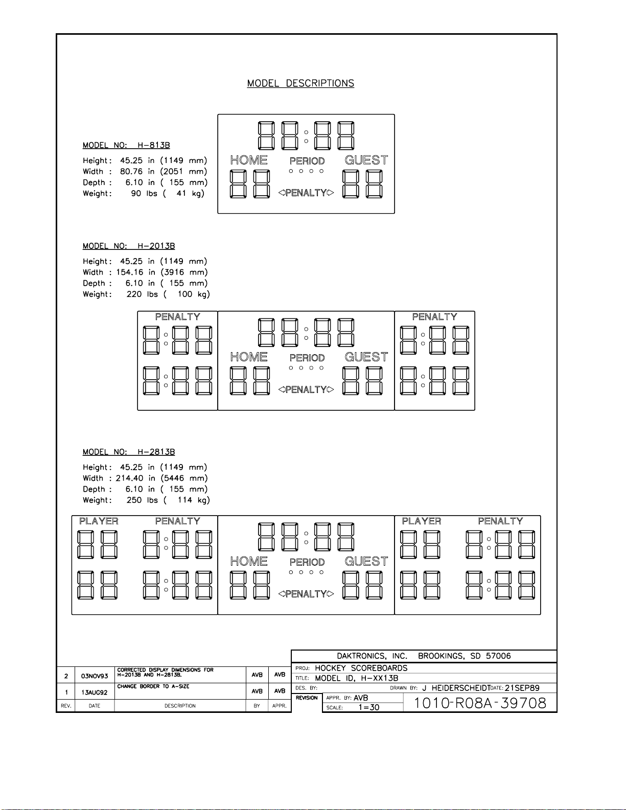
Model ID, H-XX13B..............................................Drawing A-39708
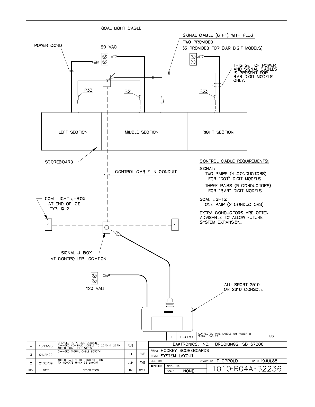
System Layout.....................................................Drawing A-32236
Your Daktronics Hockey Scoring System is one of a family of display systems designed to offer
simple installation, easy readability, and reliability. Microprocessor control assures consistent
operation and accuracy.
Six display models, H-813S, H-2013S, H-2813S, H-813B, H-2013B, and H-2813B are covered by this
manual, which is provided to assist you in installing and operating your system, and as an aid to you if
the display needs service.
1.1 How To Use This Manual
This manual explains the installation, operation, maintenance and troubleshooting of the East
Carolina University display system. For questions regarding the safety, installation, operation
or service of this system, please refer to the telephone numbers listed on the cover page of this
manual.
Important Safeguards:
1. Read and understand these instructions before installing.
2. Do not drop the control console or allow it to get wet.
3. Be sure the display is properly grounded with a ground rod at the display location.
4. Disconnect power to the display when it is not in use.
5. Disconnect power when servicing the display.
6. Do not modify the display structure or attach any panels or coverings to the
display without the written consent of Daktronics, Inc.
Daktronics identifies manuals by an ED number located on the cover page of each manual.
Any reference manuals called out in this manual will be identified by its ED number. For
example, this manual would be referred to as ED-3364.
The box below illustrates Daktronics drawing numbering system. This number is located in
the lower-right corner of the drawing. Drawings in the manual are identified by listing the last
set of digits and the letter preceding them. In the example below, the drawing would be
referred to as Drawing A-69945. Referenced drawings are inserted at the end of the section
that references them.
Introduction 1-1
Page 6

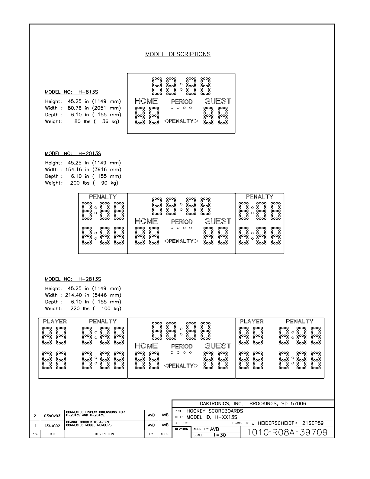
1.2 Model Identification
The figures on Drawing A-39709 show the three dot-digit display models covered in this
manual. The figures on Drawing A-39708 show the three bar-digit display models covered in
this manual. Also listed are the dimensions and weight of each display. Display model
number and electrical requirements are found on a label on the front of the display, to the left
of the period indicator lights.
1-2 Introduction
Page 7
Page 8
Page 9
Page 10

Page 11

Section 2: INSTALLATION
Reference Drawings: Scoreboard Mounting............................................Drawing A-26861
Display Interconnections ......................................Drawing A-28822
Signal Connection, 16-Pin....................................Drawing A-31808
Refer to Drawing A-32236 for general system configuration.
1. Provide grounded 120 VAC circuits to display and control locations.
2. Route control signal cable in conduit from the control location to the display location. Two
pairs of conductors (22 AWG min.) are required for each display. One-half-inch conduit is
adequate for these wires.
3. If existing cable in good condition is available, four conductors from it may be used. Cable
should run less than 1000 feet from the control location to the display. For greater lengths,
contract Daktronics.
4. Mount the display sections as described below and Drawing A-26861.
5. For dot-digit models, H-2013S and H-2813S, connect display sections together as shown in
Drawing B-28822. These connections are not applicable for dot-digit model H-813S or any
bar-digit model.
6. Make electrical connections as described in Drawing A-31808 and Section 2.2.
2.1 Mounting
Holes for lifting the display and for attaching the display to the wall are provided in the frame
of the display, as shown in Drawing A-26861.
Due to the variety of wall materials used in sports facilities, we can not anticipate your needs
and provide a mounting bolt or anchor suited to your installation. Suitable mounting
hardware may be purchased at your local hardware store. Bolts with expansion or toggle
anchors are available for a variety of wall materials. Be sure that the method you choose is
adequate to safely support the weight of the display.
Use the holes in the end of the frame to lift the display. Secure the display to the wall with the
holes in the back, as shown in Drawing A-26861. Two holes at the bottom of the display are
provided to secure the bottom of the display to the wall in a similar manner.
2.2 Electrical Installation
Electrical installation involves routing of power and control signal wiring through separate
conduit or wire ways. Control signal cable is not provided as part of this system and can be
purchased locally.
Installation 2-1
Page 12

2.2.1 Power
2.2.2 Signal
Each display is equipped with a 120 VAC, 3-prong plug. Provide two grounded
receptacles and plug it in. Actual maximum display power consumption is as follows:
Model No. Max. Power
------------- --------------H-813S 300 watts
H-813B 400 watts
H-2013S 700 watts
H-2013B 950 watts
H-2813S 950 watts
H-2813B 1300 watts
The control console requires a grounded 120 VAC receptacle for power. Power
requirement is less than one amp.
Route conduit and cable between display location(s) and the control location. Use
paired cable, minimum 22 AWG, connecting the cable to the junction box at the
control end. Connect the phone plugs provided to the display end of the cable. Insert
plugs into the jacks on the top of the display. Make connections according to the
drawing on the next page, and chart below.
DISPLAY LOCATION CONTROL
LOCATION
Red Red Center Section
Black Black
Red White Left Section
Black Green
Red Orange Right Section
(Bar Digit Only)
Black Blue
2-2 Installation
Page 13

Page 14

Page 15

Page 16

Page 17

Section 3: Maintenance & Troubleshooting
IMPORTANT NOTES:
1. Disconnect power before any repair or maintenance work is done on
the scoreboard display!
2. Any access to internal display electronics must be made by qualified
service personnel.
3. Disconnect power when the scoreboard display is not in use.
Reference Drawings: Lamp Service, 13" 4x7 DOT Matrix Digit ..............Drawing A-26872
Lamp Service, 7 Segment Bar Digit...................... Drawing A-38533
Lamp Driver, 16 Col, w/o Fan...............................Drawing A-37073
Segmentation, 4x7 Digit........................................Drawing A-26762
Segmentation, 7 Segment Bar Digit......................Drawing A-38532
Driver Assignments, H-XX13S..............................Drawing A-28860
Driver Assignments, H-XX13B..............................Drawing A-39711
Component Locations, H-XX13S..........................Drawing A-28823
Component Locations, H-XX13B..........................Drawing A-39710
3.1 Lamp Service
The primary service required by Daktronics Hockey Scoring Systems is to replace lamps
periodically. The replacement lamp is type no. 656, 28V, 60 ma, wedge base and the
Daktronics part number is DS-1115. Do not use a higher powered lamp or a lamp rated for
different voltage or damage may result.
Lamp replacement procedure is illustrated in Drawings A-26872 and A-38533.
3.2 Lamp Driver
In each display the task of switching lamps on and off is performed by the Lamp Driver
(Drawing A-37073). Each Lamp Driver has 20 connectors providing power and signal inputs
and outputs to digits and indicators. The function of each of these connectors is as follows:
Connector Function
1 thru 16 Outputs to digits and indicators
17 Control signal input
18 Power for connectors 1 thru 8
19 Power (120V) for driver logic
20 Power for connectors 9 thru 16
Output connectors 1 through 16 each have 9 pins. Pin 7 provides power to the digit or
indicators wired to that connector. The other 8 pins provide switching connections. Drawings
A-28860 and A-39711 show which connector number or connector and pin number, operates
each digit or indicator in each display model.
Maintenance & 3-3
Troubleshooting
Page 18

3.3 Segmentation
In each digit, certain lamps always go on and off together. These groupings of lamps are
referred to as "segments". Drawings A-26762 and A-38532 show which connector pin
number is wired to each digit segment, and the wiring color code used throughout the display.
3.4 Fuses
The lamp driver in the scoreboard has 17 fuses. There is one fuse to protect each digit circuit.
These fuses are type AGC-10 (refer to Drawing A-37073) and are located next to each digit
output under a single metal cover.
The other fuse, F17, is type AGC-1/2. It is located near the left end of the driver, under the
same cover as F1 through F16. This fuse protects the driver logic circuit and the fan.
Additionally, each display section has one fuse, F401, located behind the access door, to
protect 120 VAC wiring circuits.
Replace fuses only with fuses of the same type and rating.
3.5 Component Location and Access
Drawing A-28823 shows front views of the three dot-digit display models covered here, and
the locations of the various components. Drawing A-39710 shows the same thing for the
three bar-digit display models covered here. The component numbers correspond to the
schematic, Drawing A-28380 (at the end of Appendix A).
Refer to Drawing A-26762 for locations of lamp drivers and other components.
The lamp driver is located behind the indicator panel. Remove the screws securing the bottom
of the panel to gain access.
3-4 Maintenance &
Troubleshooting
Page 19

3.6 Troubleshooting
The following is a list of possible problems and the remedy for them. It is not inclusive of
every possible problem.
Observed Problem Possible Cause Remedy
Display won’t light • Console not connected or
poor connection.
• No power to console.
• Power off at source.
• Fuse blown at display.
• Driver logic fuse blown.
Individual lamps won’t light • Lamps burned out.
• Broken wire.
• Check console
connection.
• Check console power.
• Check power.
• Replace fuse.
• Replace fuse.
• Replace lamp.
• Locate and repair break.
Segment stays lit • Driver malfunction • Contact Daktronics
Garbled display • Console malfunction.
• Poor signal connection.
• Driver malfunction.
Entire digit won’t light • Broken wire.
• Fuse blown in driver.
• Contact Daktronics.
• Check console
connections.
• Contact Daktronics.
• Locate and repair break.
• Replace fuse.
3.7 Replacement Parts
The following is a list of replacement parts for the hockey scoring systems.
Description Component
Reference #
Fuse; AGC-1/2 F17 Driver Logic F-1000
Fuse; AGC-10 F1-F16 Driver Outputs F-1006
Fuse; ABC-10 F401 Main F-1007
Fuseholder; Panel Mount Main Fuse X-1032
Lamp; #656 Wedge Base Digits, Indicator DS-1115
Lampholder; T-3 1/4
Digits, Indicator X-1075
Wedge Base
Horn; 24 VAC 60Hz LS1 All Models DS-1119
Plug; 1/4" phone Signal Connection P-1041
Plug; 4-Pin MIC P101 H-813S & H-813B P-1115
Junction Box; 16 Pin Signal Connection 0A-1010-0026
Jack; 4-Pin MIC J101 H-813S & H-813B J-1124
Lamp Driver; 16 column A101 All Models 0A-1033-0043
Relay; 24 VAC K1 H-813S & H-813B K-1014
Maintenance & 3-5
Troubleshooting
Where Used Daktronics
Part #
Page 20

3.8 Daktronics Exchange/Repair & Return Programs
To serve customer’s repair and maintenance needs, Daktronics offers both an exchange and a
repair and return program. The exchange program reduces down time by providing timely
replacements parts for key components. This service is provided to qualified customers who
follow the program guidelines explained below. It is our pleasure to provide this service to
ensure you get the most from your Daktronics products. Please call our Help Desk (1-800 /
843-9879) if you have any questions regarding the exchange program or any other Daktronics
service.
When you call the Daktronics Help Desk, a trained service technician will work with you to
solve the equipment problem. You will work together to diagnose the problem and determine
which exchange replacement part to ship. If, after you make the exchange, the equipment still
causes problems, please contact our Help Desk immediately.
If the replacement part fixes the problem, package the defective part in the same packaging the
replacement part arrived in, fill out and attach the enclosed UPS shipping document and
RETURN THE PART TO DAKTRONICS. (You may use the same box and packing the
exchange part was sent in.) This will speed up the transaction and alleviate confusion when
the failed component arrives at Daktronics. (Daktronics expects immediate return of the
exchange part if it does not solve the problem.) For most equipment, you will be invoiced for
the replacement part at the time it is shipped. This invoice is due when you receive it.
Daktronics reserves the right to refuse equipment that has been damaged due to acts of nature
or causes other than normal wear and tear.
If the defective equipment is not shipped to Daktronics within 30 working days from the
invoice date, it is assumed you are purchasing the replacement part and you will be invoiced
for it. This second invoice represents the difference between the exchange price and the
purchase price of the equipment. This amount is due when you receive the second invoice. If
you return the exchange equipment after 30 working days from invoice date, you will be
credited for the amount on the second invoice minus a 20 percent restocking fee.
≅To avoid a 20 percent restocking charge, please return the defective equipment within
30 days from the invoice date.
For items that are not part of our exchange program, Daktronics offers a repair and return
program.
Where to Send: To return parts for service, contact your local representative prior to
shipment to acquire a Return Material Authorization Number (RMA#). If you have no local
representative, call the Daktronics Help Desk for the RMA#. This will expedite the receiving
process.
Packaging for Return: Package and pad the item well so that it will not be damaged in
shipment. Electronic components such as printed circuit boards should either be installed in an
enclosure or should be put in an anti-static bag before boxing. Please enclose your name,
address, phone number and a clear description of the symptoms.
Mail: Daktronics, Inc., Customer Service
3-6 Maintenance &
Troubleshooting
Page 21

PO Box 5128
331 32nd Avenue
Brookings, SD 57006
Phone: Daktronics Help Desk: 1-800/843-9879
or 1-605/697-4400
Customer Service Fax: 1-605-697-4444
e-mail: helpdesk@daktronics.com
Maintenance & 3-7
Troubleshooting
Page 22

Page 23

Page 24

Page 25

Page 26

Page 27

Page 28

Page 29

Page 30

Page 31

Page 32

Page 33

APPENDIX A: SCHEMATIC
Reference Drawings: Schematic, Hockey Display..................................Drawing A-28380
Drawing A-28380 is the schematic diagram of the power and signal inputs and all 120V wiring. The
component numbers correspond to the Drawing A-26762.
DISCONNECT POWER BEFORE SERVICING DISPLAY.
Disconnect power when the display is not in use. Prolonged power-on may shorten the lives of some
electronic components.
Appendix A: Schematic A-1
Page 34

Page 35

 Loading...