

Page 1

GalaxyPro® Revolution
Series Single Section Display
Installation & Oper ation Manual
DD1359021 Rev 15 – 6 September 2012
201 Daktronics Drive PO Box 5128 Brookings, SD 57006
Tel: 866-343-3122 Fax: 605-697-4700
www.daktronics.com
Page 2
DD1359021
_._._
Product 1466, 1479, 1500, 1545
Rev 15 – 6 September 2012
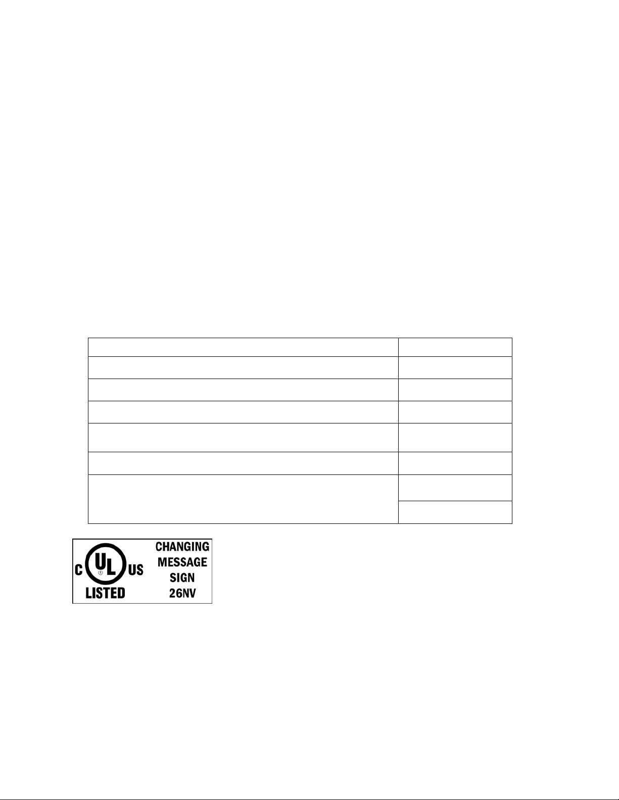
Fill in the chart with specific information about this display so these details will be readily available
when calling for service or replacement parts.
Information needed Fill in the blank
Location address of the display:
Model number of the display:
Version of software being used:
Method of communication being used:
(See Section 4 for guidance)
Controller version used in the display:
GPR
Venus 1500 v. _____
M4 controller
M4-GalaxyProRev
Firmware Version
Rfs _._._
DAKTRONICS, INC.
Copyright 2008-2012
All rights reserved. While every precaution has been taken in the preparation of this manual, the publisher
assumes no responsibility for errors or omissions. No part of this book covered by the copyrights hereon may be
reproduced or copied in any form or by any means – graphic, electronic, or mechanical, including photocopying,
taping, or information storage and retr iev al syste ms – without written permission of the publisher.
GalaxyPro® Revolution is a registered trademark of Daktronics, Inc. All others are trademarks of their respective companies.
Page 3

Table of Contents
Section 1: Overview of the Displays ........................................................................................... 1
1.1 Display Details ........................................................................................................................ 1
Section 2: Mechanical Installation .............................................................................................. 3
2.1 Pre-installation Checklist ....................................................................................................... 3
2.2 Support Structure Requirements .......................................................................................... 3
2.3 Lifting a Display or Display Section ..................................................................................... 4
General Lifting Notes: ..................................................................................................... 4
2.4 Optional Temperature Sensor Mounting............................................................................. 4
Section 3: Power Installation ....................................................................................................... 5
3.1 Conduit ..................................................................................................................................... 5
3.2 Overview of Power/ Signal Connection.............................................................................. 5
3.3 Power Requirements .............................................................................................................. 6
Main Disconnect .............................................................................................................. 6
3.4 Grounding ................................................................................................................................ 6
Installation with Ground and Neutral Conductors Provided ................................... 7
Important points about grounding: .............................................................................. 7
3.5 Power Connection ................................................................................................................... 8
3.6 Power Routing in the Display ............................................................................................... 9
Section 4: Signal Installation Overview .................................................................................... 11
4.1 Primary/Mirror Signal Connection .................................................................................... 11
Section 5: Start-up Procedure ................................................................................................... 13
5.1 Start-up Checklist .................................................................................................................. 13
5.2 Start-up Sequence ................................................................................................................. 14
5.3 Post Installation Checklist .................................................................................................... 14
Section 6: Maintenance .............................................................................................................. 15
6.1 Proper Ladder Use ................................................................................................................ 16
6.2 Access to Display Interior .................................................................................................... 16
6.3 Ventilation System/Fans/Filters ........................................................................................ 17
Frequency of Inspection ................................................................................................ 17
Fan Blades ....................................................................................................................... 18
Table of Contents i
Page 4

Filters ............................................................................................................................... 18
Air Flow ........................................................................................................................... 18
6.4 Display Face Cleaning .......................................................................................................... 19
Wet Cleaning Process .................................................................................................... 19
Dry Cleaning Process .................................................................................................... 19
6.5 Annual Inspection ................................................................................................................. 20
Section 7: Diagnostics and Troubleshooting ........................................................................... 21
7.1 Safety Precautions ................................................................................................................. 21
7.2 Controller Diagnostics .......................................................................................................... 21
7.3 MLC Diagnostics ................................................................................................................... 22
7.4 Temperature Sensor Diagnostics ........................................................................................ 22
7.5 Troubleshooting Display Problems .................................................................................... 22
Module and LED problems .......................................................................................... 22
Before calling Daktronics Customer Service .............................................................. 24
Section 8: Parts Replacement .................................................................................................... 25
8.1 About Replacement Parts ..................................................................................................... 25
8.2 Instructions for Replacing Parts .......................................................................................... 26
Module Replacement ..................................................................................................... 26
Controller Replacement ................................................................................................ 27
Multi-Line Controller Replacement............................................................................. 28
Power Supply Replacement .......................................................................................... 28
Light Sensor Replacement ............................................................................................ 29
Temperature Sensor Replacement ............................................................................... 30
Section 9: Daktronics Exchange and Repair & Return Programs .......................................... 31
9.1 Exchange Program ................................................................................................................ 31
Before Contacting Daktronics ...................................................................................... 31
9.2 Repair & Return Program .................................................................................................... 32
Shipping Address .......................................................................................................... 32
9.3 Daktronics Warranty and Limitation of Liability ............................................................. 32
Glossary .................................................................................................................................... 33
Appendix A: Reference Drawings.................................................................................................. 35
Appendix B: International Installation .......................................................................................... 37
ii Table of Contents
Page 5

Appendix C: Maintenance Log ...................................................................................................... 39
Appendix D: Daktronics Warranty and Limitation of Liability ................................................... 41
Table of Contents iii
Page 6

Page 7

Section 1: Overview of the Displays
GPR-RxC-M-L-F
GPR
R
C
L
Daktronics GalaxyPro® Revolution displays can show a wide variety of presentations with great color
depth. Figure 2 shows the front and back views of a typical display. Figure 3 shows a simplified
diagram of basic display setup.
1.1 Display Details
GalaxyPro® Revolution model numbers are defined as follows:
= Outdoor GalaxyPro® Revolution display
= Number of pixel rows high
= Number of pixel columns long
Pixel pitch: 12EV – “12 Evolution” pixels,
M
F
The displays are either single-face (SF) or two
view (2V) units. In 2V units, the first display is
referred to as the primary and the second is
called the mirror. If the second display is
mounted more than 10 feet (3.05 m) from the
primary display, two primary displays are used.
A module is the building block of the
GalaxyPro
a 20mm module measuring 16 pixels high by 16
pixels wide (other modules will vary).
Individual modules can be easily removed from
the display if needed.
A typical display system consists of a
Windows
1500 software and one or more displays. Venus
1500 is a software package that runs under Windows
operating systems on an IBM
operation of the Venus
=
all others in millimeters
= LED Color: R (Red), G (Green), B (blue)
Face setup: SF – Single Face or 2V –
=
Primary/Mirror
®
Revolution display. Figure 1 shows
®
-based computer running Venus®
®
®
-compatible computer. Refer to the Venus® 1500 Help file for
1500 software.
®
Figure 1: Single Module
®
XP or Vista Home/Professional
Display Overview 1
Page 8

Figure 2: Display Components
Figure 3: Basic Display Setup
2 Display Overview
Page 9

Section 2: Mechanical Installation
Read the mechanical, power, and signal installation sections before installing the display(s).
Daktronics' engineering staff must approve any changes that may affect the weather-tightness of the
display. Detailed drawings of the changes must be submitted to Daktronics for evaluation and
approval, or the warranty may be void.
Daktronics is not responsible for installations or the structural integrity of support structures done by
others. The customer must ensure a qualified structural engineer approves the structure and any
additional hardware.
2.1 Pre-installation Checklist
Verify the following before installation:
• The display is in good condition after shipping and uncrating.
• A straight and square mounting frame is provided for the display.
• Height variation in any 4-ft. (1.2 m) horizontal section must not exceed
• Adequate support is provided for the display so that the structure will not yield at
any unsupported points after mounting.
• Leave 4 inches (10.2 cm) of unobstructed space above the display so the eyebolt can
be removed.
No clearance is required once the eyebolt is removed.
• Maintain clearance around the display to allow unobstructed air flow through the
vents and fans and to allow access to internal components.
• Assure the display cabinet has no holes (accidental or intentional) that could allow
water to enter the display.
• Check that all display modules are fully latched into the display cabinet.
1
/4" (6.3 mm).
2.2 Support Structure Requirements
The installer must ensure the mounting structure and
hardware can support the display, and that the structure
follows all local and national structural codes. Support
structure design depends on the mounting method,
display size, and weight.
Because every installation site is unique, no single
procedure is approved by Daktronics for mounting
GalaxyPro
general information that may or may not be appropriate
for this particular installation. Refer to Figure 2 and
Figure 3 for basic display setups.
Mechanical Installation 3
®
Revolution displays. This section contains
Figure 4: Display Ventilation
Page 10

Also remember the location of mounting clips and the clearance needed for the power/signal
terminations on
the back of the
display and
ventilation system
on the front of the
display, as shown
in Figure 4 and
Figure 5. Display
height and wind
loading are also
critical factors to
consider. Find this
information on the
Shop Drawing
which was
supplied with the
order.
Figure 5: Back Section
2.3 Lifting a Display or Display Section
Maintain a 90-degree angle between the
cabinet and lifting method to retain the
cabinet’s structural integrity.
If damage occurs due to improper lifting
procedures, the warranty will be void.
General Lifting Notes:
Lift the display into position on the
support structure using a lifting bar and
all eyebolts, as shown in Figure 6.
Do not attempt to permanently support
the display by the eyebolts.
After installation is complete, carefully inspect the display for any holes that may allow water
to seep into the display and seal them with silicone.
If the eyebolts on the top of the display were removed, plug the holes with bolts and the
rubber-sealing washer that was removed with the eyebolt.
Refer to Section 3 for power routing and to the appropriate communication manual for
signal connections to the display.
Figure 6: Lifting the Display
2.4 Optional Temperature S e ns or Mounting
If an optional temperature sensor is used with this display, refer to Appendix B for mounting
and signal connections.
4 Mechanical Installation
Page 11

Section 3: Power Installation
Read the mechanical, power, and signal installation sections before installing the display(s).
Only a qualified individual should terminate power and signal cable at this Daktronics display.
All proposed changes must be approved by Daktronics engineering staff or the warranty will be null
and void.
3.1 Conduit
Daktronics does not include the conduit. Separate conduit must be used to route:
• Power.
• Signal IN wires to the signal termination enclosure, when applicable.
• Signal OUT wires (if not using the provided interconnect cable).
Some displays have a J box on the back for power termination which has
threaded holes, while others have a
on the back for power entry. In this case, power is terminated to an internal power
termination panel. Refer to the shop drawing to determine which type of display is being
installed.
3
/4" hole for conduit, and is capped with a rubber plug
3.2 Overview of Power/ Signal Connection
Following is a brief summary of the power and signal connections to the display.
1. Possible methods for signal termination are shown in the manual for the specific
communication type.
2. Power is routed to the display through a fused disconnect switch that can open all
ungrounded power conductors. Install this disconnect within the line of sight of
personnel performing maintenance on the display. (If the disconnect is located out of
sight of the display, it must be capable of being locked in the open position.)
3. Route power conductors from the disconnect to the display through conduit
according to local and national electrical codes.
4. Display power terminates either internally at the power termination panel or
externally at the J box.
5. Connect the grounding electrode conductor at the grounding lug on the back of the
display.
6. Route signal cable to the signal termination enclosure. When required, the signal
enclosure must be grounded.
7. Route signal into the enclosure through
with rubber plug.
3
/4"conduit. Use supplied hole that is capped
3
/4" (1.905 cm)
Power Installation 5
Page 12

8. Route the signal quick-connect cable from the enclosure to the display through
conduit or through the display pole if power is not also routed in the display pole.
Daktronics strongly recommends the quick-connect cables be secured to protect them from
weather or vandalism.
Displays are equipped with circuit breakers that carry a UL489 or UL1077 (IEC 60947, VDE
660) rating. These devices only protect the components within the display. Suitable devices
must be used for the equipment and feeders supplying power to the display.
3.3 Power Requirements
Do not connect the displays to any voltage other than that listed on the Daktronics product
label.
Conductors of circuits delivering power to a Daktronics display must be sized according to
local and national electrical codes so that the power distribution system can deliver full-load
power to the display while maintaining a voltage within 5 percent of the utility nominal
voltage.
Displays use single-phase power. Proper power installation is imperative for proper display
operation. Power Specifications are found in Appendix A. The following sub-sections
provide details of power installation.
Main Disconnect
Daktronics requires using a power disconnect switch with the display. Use a disconnect
switch so that all ungrounded conductors can be disconnected near the point of power
connection.
The disconnecting means must be either located in a direct line of sight from the display or
capable of being locked in the open position. This ensures that power will not be reconnected
while service personnel work on the display.
3.4 Grounding
Displays must be grounded according to the provisions outlined in all applicable local and
national electrical codes.
6 Power Installation
Page 13

Installation with Ground and Neutral Conductors Provided
These displays are installed with ground and neutral conductors provided. The power cable
must contain an
isolated earthground conductor.
Do not connect
neutral to ground at
the disconnect or at
the display. This will
violate electrical
codes and render the
warranty null and
void.
The display system
must be connected to
earth ground as
shown in Figure 7.
Proper grounding
protects the
equipment from
damaging electrical
disturbances and lightning. Daktronics requires a resistance to ground of 10 ohms or less.
The display must be properly grounded or the warranty will be null and void.
Figure 7: Correct Grounding
Important points about grounding:
• Follow local and national codes: The material of an earth-ground electrode differs
from region to region and from conditions present at the site. Consult any electrical
codes that apply.
• Support structure cannot be used as an earth-ground electrode: The support is
generally embedded in concrete, and if embedded in earth, the steel is either primed
or it corrodes, making it a poor ground.
• One grounding electrode for each display face: Grounding is connected between
sections by bonding jumpers. Other grounding electrodes as described in national
and local electrical codes may be used.
• Resistance to ground 10 ohms or less: This is required by Daktronics for proper
display performance. If the resistance to ground is higher than 10 ohms, it is
necessary to install additional grounding electrodes to reduce resistance. The
grounding electrode must be installed within 25 feet (7.6 m) of the display’s base and
must be connected to the ground lug on the back of the display, as shown in Figure
7.
Power Installation 7
Page 14

3.5 Power Connection
Power is terminated either internally to the
power termination board or externally to the J
box.
Terminating single-phase power to the
internal power termination panel:
1. Open the display as explained in
Section 6.2 and locate the power
termination panel.
2. Route the cable through conduit to the
back of the display. Remove the rubber
plug from the ¾” (1.905 cm) hole for
access, being careful not to damage
internal components.
3. If larger conduit is required, remove
metal filings from display after drilling.
4. Connect the neutral wire to the neutral
lug and the live wires to Line 1 and
Line 2. Refer to Figure 8.
5. The ground wire connects to the
grounding bus bar.
Terminating hot, neutral, and ground wires at
the J box
1. Route the power cable through
conduit to the rear of the display and
into the power termination J box.
2. The power termination enclosure
contains two or three wires plus a
ground coming from the interior of
the display. These wires are preterminated to the power termination
panel inside the display.
3. Inside the external J box, shown in
Figure 9, connect the power wires to
the wires coming from the display
interior using wire nuts.
3
/4"
Figure 8: 120/240 V Single-Phase Power
Termination
Figure 9: 120/240 VAC Power Termination
8 Power Installation
Page 15

The following colors are used for pre-terminated wires:
(two wires plus ground)
(three wires plus ground)
Line 1 - Black
Line 1 - Black
120 VAC
Neutral – White Line 2 - Red
Grounding – Green-Yellow Neutral – White
Grounding – Green-Yellow
120/240 VAC
3.6 Power Routing in the Display
Check exact power routing on Drawing B-360218 found in Appendix A.
A general power routing is
shown in Figure 10.
1. Power terminates
internally to the
power termination
panel.
2. Power is routed
through filters to
the power supplies,
which provide
power to the
controller, MLC,
modules, and fans.
Power supplies are
preset to the proper
voltage: 12 VDC.
Power Installation 9
Figure 10: Power Flow Summary
Page 16

Page 17

Section 4: Signal Inst allation Overv ie w
Communication Type
Communication Manual
Communication Quick Guide
Daktronics GalaxyPro® Revolution displays are equipped to receive various forms of Ethernet
communication. GalaxyPro
®
Revolution displays require the use of ports 4500-4525 for
communication and port forwarding applications. For communication signal installation details,
consult the quick guide and manual included with the communication equipment. Each
communication type and its manual number are listed below.
Ethernet DD1417609
Fiber Ethernet DD1417611 DD1417581
Wireless Ethernet Bridge DD1685027 DD1417586
DD1417573
These are the standard communication types, but each site is unique and may include additional
equipment. If problems arise, contact the display’s seller or Daktronics Customer Service.
4.1 Primary/Mirror Si gnal Conne c t ion
If this display is a two-view primary/mirror display, a quick-connect fiber-optic cable is
provided to connect signal between the two faces. Connect J34-Signal Out on the Primary
display to J32-Signal In on the Mirror display. Coil
excess cable and secure it to the supports to prevent
damage from weather or vandalism. Figure 11 and
Figure 12 show the cable and the quick-connect
output. The signal input on the mirror display looks
similar to the quick-connect output, but is labeled
J32 and receives information from the primary
display.
Figure 11: Quick Connect Signal Cable
Signal Installation 11
Figure 12: Fiber Interconnect Output
 Loading...