

Page 1
Gen V Radio
Installation Manual
ED-13831 Rev 6 – 8 November 2011
201 Daktronics Drive PO Box 5128 Brookings, SD 57006-5128
Tel: 1-800-DAKTRONICS (1-800-325-8766) Fax: 605-697-4700
Web: www.daktronics.com
Table of Contents 2
Page 2

Page 3

ED-13831
P1322
Rev 6 – 8 November 2011
DAKTRONICS, INC.
Copyright 2007-2011
All rights reserved. While every precaution has been taken in the preparation of this manual, the publisher
assumes no responsibility for errors or omissions. No part of this book covered by the copyrights hereon may be
reproduced or copied in any form or by any means - graphic, electronic, or mechanical, including photocopying,
taping, or information storage and retrieval systems - without written permission of the publisher.
All Sport® is a registered trademark of Daktronics, Inc. All other trademarks are the property of their respective companies.
Page 4

Page 5

Table of Contents
Table of Contents .................................................................................................................................. i
Section 1: Installation ................................................................................................................... 1
1.1 Radio Receiver ......................................................................................................................... 1
Indoor Scoreboards .......................................................................................................... 1
Outdoor Scoreboards ...................................................................................................... 1
1.2 RC-100 Base Station ................................................................................................................ 1
Section 2: Setting Radio Channels ............................................................................................. 3
2.1 Radio Control Overview ........................................................................................................ 3
2.2 Typical Radio Configurations ............................................................................................... 3
Single Controller System................................................................................................. 4
Multiple Controller System with Single Broadcast Group ........................................ 5
Multiple Controller with Multiple Broadcast Groups ................................................ 7
Section 3: Daktronics Exchange and Repair & Return Programs .......................................... 9
3.1 Exchange Program .................................................................................................................. 9
Before Contacting Daktronics ........................................................................................ 9
3.2 Repair & Return Program .................................................................................................... 10
Shipping Address .......................................................................................................... 10
3.3 Daktronics Warranty and Limitation of Liability ............................................................. 10
Appendix A: Reference Drawings ................................................................................................. 11
Appendix B: Daktronics Warranty and Limitation of Liability ................................................... 13
Table of Contents i
Page 6

Page 7

Section 1: Installation
1.1 Radio Receiver
Reference Drawings:
Installation; Indoor, Gen V Radio Receiver ............................................ Drawing A-203542
Installation: Outdoor- Gen V Radio Receiver ......................................... Drawing A-203543
Install Details: Outdoor Radio/Wire Switch ............................................ Drawing B-235957
Installation; Radio Bracket ..................................................................... Drawing A-267405
Installation; Outdoor Gen IV Scbds,w/ Gen V Radio ............................. Drawing A-290166
Installation- Indoor Color Smart- Gen V Receiver ................................. Drawing A-298616
Most scoreboards will have an internal mounting bracket to which the radio receiver will be
attached. Refer to the component location drawings included in the scoreboard manual for
the radio mounting location. If a bracket was not factory-installed, refer to Drawing A-267405
for bracket installation instructions.
Indoor Scoreboards
For standard indoor scoreboards, refer to Drawing A-203542.
For ColorSmart® color-changing digit scoreboards, refer to Drawing A-298616.
Outdoor Scoreboards
For outdoor scoreboards built after January 2007, refer to Drawing A-290166.
For outdoor scoreboards built before January 2007, refer to Drawing A-203543.
Note: For outdoor installations that have a radio/wire switch, refer to Drawing B-235957.
1.2 RC-100 Base Station
Reference Drawings:
Base Station: Outdoor Installation ......................................................... Drawing A-236394
Outdoor Installation: Radio Receiver & Base Station .......................... Drawing A-1069855
Drawing A-236394 shows the installation of an RC-100 base station for outdoor scoreboards.
For detailed RC-100 installation and setup instructions, including indoor scoreboards, refer to
the Remote Control System RC-100 All Sport Operation Manual (ED-15133), available
online at www.daktronics.com/manuals.
In certain situations, it is possible that both an All Sport® radio receiver and an RC-100 base
station will be installed in the same outdoor scoreboard. For instance, a handheld RC-100
may be used when running practices, and then a wireless All Sport console would control the
scoreboard during the game. In these cases, refer to Drawing A-1069855.
Note: The wireless device that takes precedence is the one that the scoreboard receiver
finds active first, and it will control the scoreboard until the signal is no longer present.
Installation 1
Page 8

Page 9
Section 2: Setting Radio Channels
Figure 1: Radio Settings in Clock Digits
Figure 2: Radio Settings in Score Digits
2.1 Radio Control Overview
The radio receiver units used in Daktronics scoreboards have a channel-setting switch that
can be set from 1 through 8 (channels 0, and 9-15 are not used). The receivers also have a
jumper that can be used to select a broadcast group from 1-4. The broadcast group defines a
group of radio receivers that “listen” to the channel selected on the channel switch as well as
“listen” for data sent out on their broadcast channel.
There are four broadcast groups available. Each radio receiver will accept data sent from the
broadcast channel of its respective broadcast group (either 1, 2, 3, or 4), as well as data sent
from the “Master Broadcast” channel. This is selected when the console is set to Broadcast
Group 0 (BCAST 0) and Channel 0.
The radio settings in the console (transmitter) must match the settings in the scoreboard
(receiver). By default, both devices are set to Broadcast Group 1, Channel 01. The installation
drawings in Appendix A show the proper way to set the channel and broadcast group
numbers for the receiver. The operator must then enter these specific numbers when
prompted during console startup.
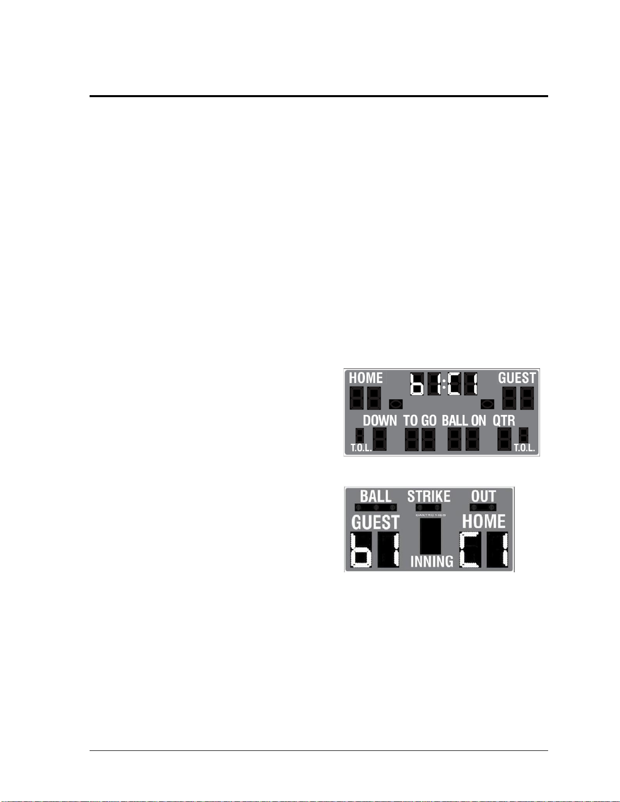
To determine the settings of a scoreboard
without accessing the receiver, first power it
down and shut off any radio-equipped
consoles in the area. Next, power the
scoreboard back up and watch for the radio
settings. The settings will appear as “bX CY”
where X is the current broadcast group and Y
is the current channel.
The settings are typically displayed in the
clock digits (Figure 1) or Home and Guest
score digits (Figure 2), depending on the
scoreboard model.
The console automatically detects when a
radio transmitter is installed and will prompt
the user for transmitter settings after a valid
sport code is entered.
2.2 Typical Radio Configurations
There are three different radio scenarios that can be accommodated: a single controller
system, a multiple controller system with a single broadcast group, and a multiple controller
system with multiple broadcast groups. Each of these configurations is described in detail in
the following sections.
Setting Radio Channels 3
Page 10
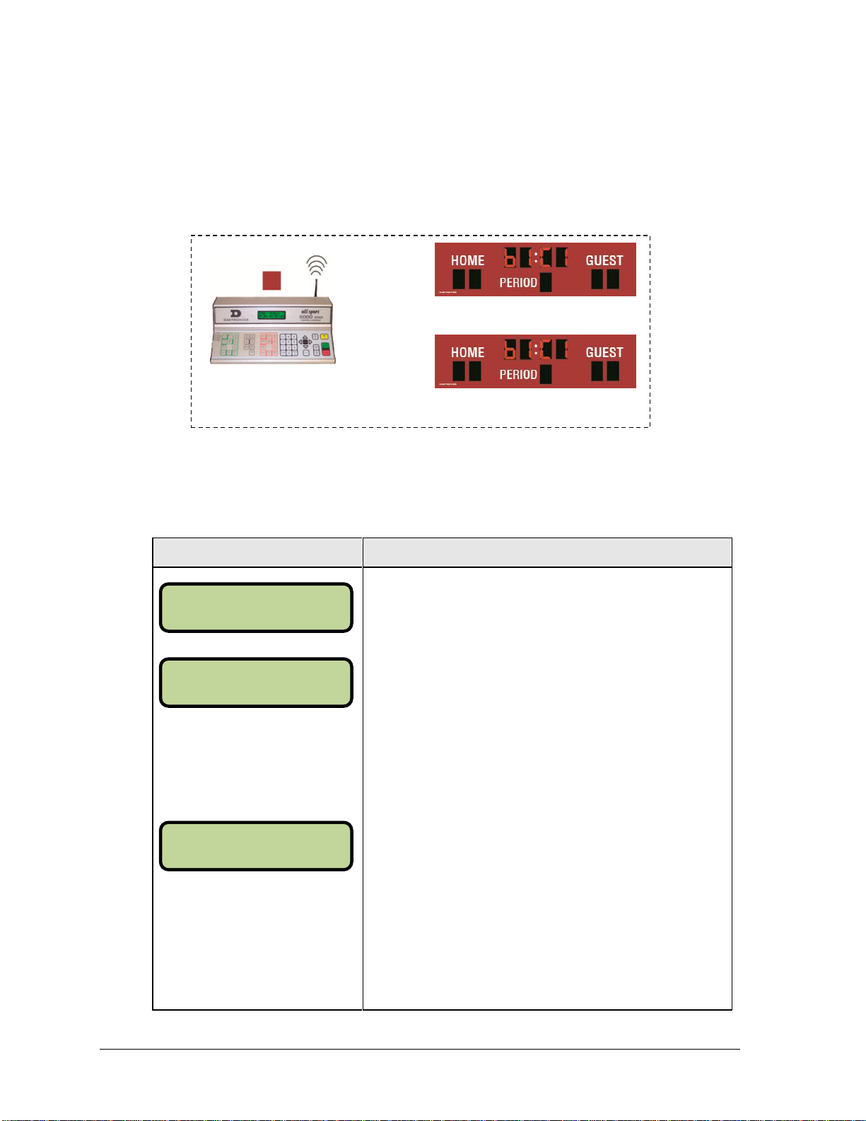
Single Controller System
Display
Action
The LCD will toggle between
these 2 screens.
The LCD shows the current radio settings along with a prompt
to accept or modify these values.
If the radio settings are correct press <ENTER>.
If these values are incorrect press <CLEAR>, and the LCD at
bottom left is shown, allowing edit of the channel or broadcast
group setting.
Broadcast Group Setting
1 Use this setting for all single controller systems. Use
the number keys to edit this value and press
<ENTER> to accept. The asterisk will move to the
channel setting.
Channel Setting
1-8 Channels 1-8 may be used with broadcast group 1.
Edit the channel number to the desired value and press
<ENTER> to accept. The channel switch on the
receiver must match this value and only the Broadcast
1 (BCAST1) jumper must be set.
Figure 3: Single Control Console
BCAST 1, CHANNEL #1
BCAST 1, CHANNEL #1
BCAST 1, CHANNEL 01
RA D I O SETT I NGS
BC A ST X CHAN YY
EN T ER TO ACCEP T
CL E AR TO MODI FY
BC A ST GROUP 1*
RA D I O CHAN 01
In a single controller system (Figure 3), all radio receivers and all scoreboards receive signal
from the same console at all times. The default channel and broadcast group settings on the
receiver are not typically modified. An example of this type of system is a football field with
a scoreboard in one or both end zones displaying the same information.
Typically all single controller systems will use the default setting BCAST = 1, CHAN = 1.
All jumpers in the radio receivers must be set to Broadcast 1 (BCAST 1).
4 Setting Radio Channels
Page 11

Multiple Controller System with Single Broadcast Group
Figure 4: Single Broadcast Group
BCAST 1, CHANNEL #1
BCAST 1, CHANNEL #2
BCAST 1,
CHANNEL 01
BCAST 1,
CHANNEL 02
BCAST 1,
CHANNEL 03
BCAST 1, CHANNEL #3
BCAST 1, CHANNEL #4
BCAST 1,
CHANNEL 04
BCAST 0,
CHANNEL 00
to control all at once
Or
BCAST 1,
CHANNEL 01-04
to control a specific
scoreboard
In a multiple controller system with a single broadcast group (Figure 4), there may be one
console for each scoreboard and/or one master controller that can run every scoreboard at
one time or take control of a specific scoreboard. An example of this type of system is a
softball complex with individual scoreboards on several different fields.
Setting Radio Channels 5
Page 12

Multiple controller systems typically use Broadcast 1 and Channel 1 for the first controller
Display
Action
The LCD will toggle between
these 2 screens.
The LCD shows the current radio settings along with a prompt
to accept or modify these values.
If the radio settings are correct press <ENTER>.
If these values are incorrect press <CLEAR>, and the LCD at
bottom left is shown, allowing edit of the channel or broadcast
group setting.
Broadcast Group Setting
1 Use this setting for all multiple controllers with single
broadcast group setups. Use the number keys to edit
this value and press <ENTER> to accept. The asterisk
will move to the channel setting.
Channel Setting
1-8 Channels 1-8 may be used with broadcast channel 1.
Edit the channel number to the desired value and press
<ENTER> to accept. The channel switch on the
receiver must match this value and only the Broadcast
1 (BCAST1) jumper must be set.
EN T ER TO ACCEP T
CL E AR TO MODI FY
RA D I O SETT I NGS
BC A ST X CHAN YY
BC A ST GROUP 1*
RA D I O CHAN 01
and Channels 2-8 for all remaining controllers. All jumpers in the radio receivers must be set
to Broadcast 1 (BCAST 1).
6 Setting Radio Channels
Page 13

Figure 5: Multiple Broadcast Group
BCAST 1, CHANNEL #1
BCAST 1, CHANNEL #2
BCAST 1, CHANNEL 01
BCAST 1, CHANNEL 02
BCAST 2, CHANNEL #1
BCAST 2, CHANNEL #2
BCAST 2, CHANNEL 01
BCAST 1, CHANNEL 00
BCAST 2, CHANNEL 02
BCAST 2, CHANNEL 00
BCAST 0, CHANNEL 00
to control all at once
Or
BCAST 1-2,
CHANNEL 01-02
to control a specific
scoreboard/group
Setting Radio Channels 7
Multiple Controller with Multiple Broadcast Groups
In a multiple controller system with multiple broadcast groups (Figure 5), there are many
consoles that control multiple scoreboards and/or scoreboard groups. The radio receiver inside
the scoreboard is set to broadcast group 1, 2, 3, or 4. By changing the console settings to the
specific broadcast group address, a single console can control all scoreboards or specific groups
of scoreboards. One example of this scenario is split court operation in basketball installations,
where scoreboards are used to score multiple games at once, but can be grouped together to
show one game if necessary. Refer to Drawing A-202943 as an example.
Page 14

Typically all multiple controller systems will use Broadcast Group 1 Channel 1 for the first
Display
Action
The LCD will toggle between
these 2 screens.
The LCD shows the current radio settings along with a prompt
to accept or modify these values.
If the radio settings are correct press <ENTER>.
If these values are incorrect press <CLEAR>, and the LCD at
bottom left is shown, allowing edit of the channel or broadcast
group setting. Use the number keys to enter the desired
broadcast group and press <ENTER> to accept. The asterisk
will move to the channel setting.
Edit the channel number to the desired value and press
<ENTER> to accept.
Broadcast
Group
Channel
Setting
Control Scoreboards
0
0
All Scoreboards
1
0
All in BCAST Group 1
1-8
Set to corresponding BCAST 1
Channel
2
0
All in BCAST Group 2
1-4
Set to Corresponding BCAST 2
Channel
3
0
All in BCAST Group 3
1-8
Set to corresponding BCAST 3
Channel
4
0
All in BCAST Group 4
1-4
Set to corresponding BCAST 4
Channel
EN T ER TO ACCEP T
CL E AR TO MODI FY
BC A ST GROUP 1*
RA D I O CHAN 01
RA D I O SETT I NGS
BC A ST X CHAN YY
controller in Broadcast Group 1 and Broadcast Group 2 Channel 1 for the first controller in
Broadcast Group 2. All other consoles in a group are added sequentially, using channels 2-8
for groups 1 and 3, and channels 2-4 for groups 2 and 4.
8 Setting Radio Channels
Page 15

Section 3: Daktronics Exchange and Repair &
Market Description
Customer Service Number
Schools (including community/junior colleges), religious
organizations, municipal clubs and community centers
877-605-1115
Universities and professional sporting events, live events
for auditoriums and arenas
866-343-6018
Return Programs
3.1 Exchange Program
The Daktronics Exchange Program is a service for quickly replacing key components in need
of repair. If a component fails, Daktronics sends a replacement part to the customer who, in
turn, returns the failed component to Daktronics. This decreases equipment downtime.
Customers who follow the program guidelines explained below will receive this service.
Before Contacting Daktronics
Identify these important numbers:
Model Number: ________________________________________________________________
Job/Contract Number: __________________________________________________________
Date Installed: _________________________________________________________________
Daktronics Customer ID Number: ________________________________________________
To participate in the Exchange Program, follow these steps.
1. Call Daktronics Customer Service.
2. When the new exchange part is received, mail the old part to Daktronics.
If the replacement part fixes the problem, send in the problem part being replaced.
a. Package the old part in the same shipping materials in which the replacement
part arrived.
b. Fill out and attach the enclosed UPS shipping document.
c. Ship the part to Daktronics.
3. The defective or unused parts must be returned to Daktronics within 5 weeks of
initial order shipment.
If any part is not returned within five (5) weeks, a non-refundable invoice will be
presented to the customer for the costs of replenishing the exchange parts inventory
with a new part.
Daktronics reserves the right to refuse parts that have been damaged due to acts of
nature or causes other than normal wear and tear.
Daktronics Exchange and Repair & Return Programs 9
Page 16

3.2 Repair & Return Program
For items not subject to exchange, Daktronics offers a Repair & Return Program. To send a
part for repair, follow these steps:
1. Call or fax Daktronics Customer Service:
Refer to the appropriate market number in the chart listed on the previous page.
Fax: 605-697-4444
2. Receive a case number before shipping.
This expedites repair of the part.
3. Package and pad the item carefully to prevent damage during shipment.
Electronic components, such as printed circuit boards, should be placed in an
antistatic bag before boxing. Daktronics does not recommend using packing
„peanuts‟ when shipping.
4. Enclose:
name
address
phone number
the case number
a clear description of symptoms
Shipping Address
Daktronics Customer Service
[Case #]
201 Daktronics Drive, Dock E
Brookings, SD 57006
3.3 Daktronics Warranty and Limitation of Liability
The Daktronics Warranty and Limitation of Liability is located in Appendix B. The Warranty
is independent of Extended Service agreements and is the authority in matters of service,
repair, and display operation.
10 Daktronics Exchange and Repair & Return Programs
Page 17

Appendix A: Reference Drawings
System Riser; Gen V or VI Mult. Broadcast/Channel Groups................................... Drawing A-202943
Installation; Indoor, Gen V Radio Receiver ............................................................... Drawing A-203542
Installation: Outdoor- Gen V Radio Receiver ............................................................ Drawing A-203543
Install Details: Outdoor Radio/Wire Switch ................................................................ Drawing B-235957
Base Station: Outdoor Installation ............................................................................. Drawing A-236394
Installation; Radio Bracket ......................................................................................... Drawing A-267405
Installation; Outdoor Gen IV Scbds,w/ Gen V Radio ................................................. Drawing A-290166
Installation- Indoor Color Smart- Gen V Receiver ..................................................... Drawing A-298616
Outdoor Installation: Radio Receiver & Base Station .............................................. Drawing A-1069855
Reference Drawings 11
Page 18

Page 19

AH
ALL SPROT RADIO
SYSTEM RISER: GEN V OR VI MULT. BROADCAST/CHANNEL GROUPS
RTAGTOW 21 JAN 04
P1110 R
01 A
NONE
MMILLER
202943
01
01 07 AUG 12 MWM
UPDATED TITLE NAME TO INCLUDE VI RADIO
ADDED TEXT TO THE RISER TO SAY V OR VI
THIS RISER LAYOUT IS FOR AN ALL GEN V RADIO SYSTEM OR AN ALL GEN VI
RADIO SYSTEM.
Page 20

Page 21

Page 22

Page 23

TX RX IN TX RX
CL / RS232 RANGE CAN
Page 24

Page 25

Page 26

B
B
PTCUR. LOOP
SIGNAL IN
SIGNAL OUT
TAN5VIO
3 4
BLKRED
1 2
PNK
7
WHT6BLU
2
1
8
9
PNK
4
3
ORG
BRNTAN
HAZARDOUS VOLTAGE
DISCONNECT POWER
BEFORE SERVICING
AT EXPOSED TERMINALS
5 10
61
7
8
ORG
3
2
BLU WHT
BRN
10
PNK
TAN
5
4 9
Page 27

TX RX IN TX RX
CL / RS232 RANGE CAN
Page 28

Page 29

Appendix B: Daktronics Warranty and Limitation
of Liability
Daktronics Warranty & Limitation of Liability 13
Page 30

Page 31

Copyright © Daktronics, Inc. SL-02374 Rev 10 02-Mar-2009 Page 1 of 2
DAKTRONICS
WARRANTY AND LIMITATION OF LIABILITY
This Warranty and Limitation of Liability (the “Warranty”) sets forth the warranty provided by Daktronics with respect to the Equipment. By
accepting delivery of the Equipment, Purchaser agrees to be bound by and accept these terms and conditions. All defined terms within
the Warranty shall have the same meaning and definition as provided elsewhere in the Agreement.
DAKTRONICS WILL ONLY BE OBLIGATED TO HONOR THE WARRANTY SET FORTH IN THESE TERMS AND CONDITIONS UPON RECEIPT OF FULL
PAYMENT FOR THE EQUIPMENT.
1. Warranty Coverage
2. Exclusion from Warranty Coverage
A. Daktronics warrants to the original end-user that the Equipment will be free from Defects (as defined below) in materials and
workmanship for a period of one (1) year (the “Warranty Period”). The warranty period shall commence on the earlier of: (i) four
weeks from the date that the equipment leaves Daktronics’ facility; or (ii) Substantial Completion as defined herein. The warranty
period shall expire on the first anniversary of the commencement date.
“Substantial Completion” means the operational availability of the Equipment to the Purchaser in accordance with the
Equipment’s specifications, without regard to punch-list items, or other non-substantial items which do not affect the operation of
the Equipment.
B. Daktronics’ obligation under this Warranty is limited to, at Daktronics’ option, replacing or repairing, any Equipment or part
thereof that is found by Daktronics not to conform to the Equipment’s specifications. Unless otherwise directed by Daktronics,
any defective part or component shall be returned to Daktronics for repair or replacement. Daktronics may, at its option,
provide on-site warranty service. Daktronics shall have a reasonable period of time to make such replacements or repairs and
all labor associated therewith shall be performed during regular working hours. Regular working hours are Monday through
Friday between 8:00 a.m. and 5:00 p.m. at the location where labor is performed, excluding any holidays observed by either
Purchaser or Daktronics.
C. Daktronics shall pay ground transportation charges for the return of any defective component of the Equipment. If returned
Equipment is repaired or replaced under the terms of this warranty, Daktronics will prepay ground transportation charges back to
Purchaser; otherwise, Purchaser shall pay transportation charges to return the Equipment back to the Purchaser. All returns must
be pre-approved by Daktronics before shipment. Daktronics shall not be obligated to pay freight for any unapproved return.
Purchaser shall pay any upgraded or expedited transportation charges.
D. Any replacement parts or Equipment will be new or serviceably used, comparable in function and performance to the
original part or Equipment, and warranted for the remainder of the Warranty Period. Purchasing additional parts or Equipment
from the Seller does not extend this Warranty Period.
E. Defects shall be defined as follows. With regard to the Equipment (excepting LEDs), a “Defect” shall refer to a material
variance from the design specifications that prohibit the Equipment from operating for its intended use. With respect to LEDs,
“Defects” are defined as LED pixels that cease to emit light. The limited warranty provided by Daktronics does not impose any
duty or liability upon Daktronics for partial LED pixel degradation. Nor does the limited warranty provide for the replacement or
installation of communication methods including but not limited to, wire, fiber optic cable, conduit, trenching, or for the purpose
of overcoming local site interference radio equipment substitutions.
THIS LIMITED WARRANTY IS THE ONLY WARRANTY APPLICABLE TO THE EQUIPMENT AND REPLACES ALL OTHER WARRANTIES OR
CONDITIONS, EXPRESS OR IMPLIED, INCLUDING, BUT NOT LIMITED TO, THE IMPLIED WARRANTIES OR CONDITIONS OF
MERCHANTABILITY AND FITNESS FOR A PARTICULAR PURPOSE. SPECIFICALLY, EXCEPT AS PROVIDED HEREIN, THE SELLER
UNDERTAKES NO RESPONSIBILITY FOR THE QUALITY OF THE EQUIPMENT OR THAT THE EQUIPMENT WILL BE FIT FOR ANY PARTICULAR
PURPOSE FOR WHICH PURCHASER MAY BE BUYING THE EQUIPMENT. ANY IMPLIED WARRANTY IS LIMITED IN DURATION TO THE
WARRANTY PERIOD. NO ORAL OR WRITTEN INFORMATION, OR ADVICE GIVEN BY THE COMPANY, ITS AGENTS OR EMPLOYEES,
SHALL CREATE A WARRANTY OR IN ANY WAY INCREASE THE SCOPE OF THIS LIMITED WARRANTY.
THIS LIMITED WARRANTY IS NOT TRANSFERABLE.
The limited warranty provided by Daktronics does not impose any duty or liability upon Daktronics for:
A Any damage occurring, at any time, during shipment of Equipment unless otherwise provided for in the Agreement. When
returning Equipment to Daktronics for repair or replacement, Purchaser assumes all risk of loss or damage, and agrees to use
any shipping containers that might be provided by Daktronics and to ship the Equipment in the manner prescribed by
Daktronics;
B. Any damage caused by the unauthorized adjustment, repair or service of the Equipment by anyone other than personnel of
Daktronics or its authorized repair agents;
Page 32

Copyright © Daktronics, Inc. SL-02374 Rev 10 02-Mar-2009 Page 2 of 2
C. Damage caused by the failure to provide a continuously suitable environment, including, but not limited to: (i) neglect or
misuse, (ii) a failure or sudden surge of electrical power, (iii) improper air conditioning or humidity control, or (iv) any other cause
other than ordinary use;
D. Damage caused by fire, flood, earthquake, water, wind, lightning or other natural disaster, strike, inability to obtain materials
or utilities, war, terrorism, civil disturbance or any other cause beyond Daktronics’ reasonable control;
E. Failure to adjust, repair or replace any item of Equipment if it would be impractical for Daktronics personnel to do so because
of connection of the Equipment by mechanical or electrical means to another device not supplied by Daktronics, or the
existence of general environmental conditions at the site that pose a danger to Daktronics personnel;
F. Any statements made about the product by salesmen, dealers, distributors or agents, unless such statements are in a written
document signed by an officer of Daktronics. Such statements as are not included in a signed writing do not constitute
warranties, shall not be relied upon by Purchaser and are not part of the contract of sale;
G. Any damage arising from the use of Daktronics products in any application other than the commercial and industrial
applications for which they are intended, unless, upon request, such use is specifically approved in writing by Daktronics; or
H. Any performance of preventive maintenance.
3. Limitation of Liability
4. Assignment of Rights
5. Dispute Resolution
6. Governing Law
7. Availability of Extended Service Agreement
Daktronics shall be under no obligation to furnish continued service under this Warranty if alterations are made to the Equipment
without the prior written approval of Daktronics.
It is specifically agreed that the price of the Equipment is based upon the following limitation of liability. In no event shall
Daktronics (including its subsidiaries, affiliates, officers, directors, employees, or agents) be liable for any special, con sequential,
incidental or exemplary damages arising out of or in any way connected with the Equipment or otherwise, including but not
limited to damages for lost profits, cost of substitute or replacement equipment, down time, lost data, injury to property or any
damages or sums paid by Purchaser to third parties, even if Daktronics has been advised of the possibility of such damages. The
foregoing limitation of liability shall apply whether any claim is based upon principles of contract, tort or statutory duty, principles
of indemnity or contribution, or otherwise.
In no event shall Daktronics be liable to Purchaser or any other party for loss, damage, or injury of any kind or nature arising out of
or in connection with this Warranty in excess of the purchase price of the Equipment actually delivered to and paid for by the
Purchaser. The Purchaser’s remedy in any dispute under this Warranty shall be ultimately limited to the Purchase Price of the
Equipment to the extent the Purchase Price has been paid.
The Warranty contained herein extends only to the original end-user (which may be the Purchaser) of the Equipment and no
attempt to extend the Warranty to any subsequent user-transferee of the Equipment shall be valid or enforceable without the
express written consent of Daktronics.
Any dispute between the parties will be resolved exclusively and finally by arbitration administered by the American Arbitration
Association (“AAA”) and conducted under its rules, except as otherwise provided below. The arbitration will be conducted
before a single arbitrator. The arbitration shall be held in Brookings, South Dakota. Any decision rendered in such arbitration
proceedings will be final and binding on each of the parties, and judgment may be entered thereon in any court of competent
jurisdiction. This arbitration agreement is made pursuant to a transaction involving interstate commerce, and shall be governed
by the Federal Arbitration Act.
The rights and obligations of the parties under this warranty shall not be governed by the provisions of the United Nations
Convention on Contracts for the International Sales of Goods of 1980. Both parties consent to the application of the laws of the
State of South Dakota to govern, interpret, and enforce all of Purchaser and Daktronics rights, duties, and obligations arising
from, or relating in any manner to, the subject matter of this Warranty, without regard to conflict of law principles.
For Purchaser’s protection, in addition to that afforded by the warranties set forth herein, Purchaser may purchase extended
warranty services to cover the Equipment. The Extended Service Agreement, available from Daktronics, provides for electronic
parts repair and/or on-site labor for an extended period from the date of expiration of this warranty. Alternatively, an Extended
Service Agreement may be purchased in conjunction with this warranty for extended additional services. For further information,
contact Daktronics Customer Service at 1-800-DAKTRONics (1-800-325-8766).
 Loading...