

Page 1
Rear-Ventilated GalaxyPro® GP3 and GP4 Display Installation Quick Guide
Complete these steps in order during the installation process.
Step 1: Display Mounting
Refer to Section 3 of display manual for additional
information.
Note: For Multi-Section Displays – See reverse side of this
document for section splicing instructions.
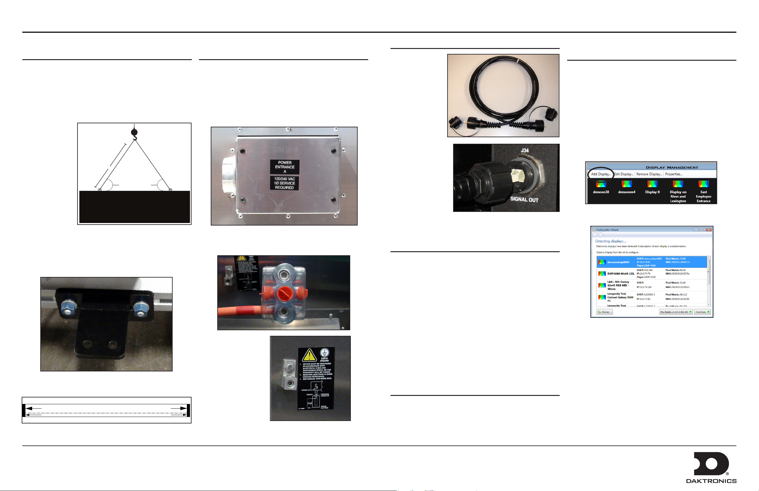
1. Lift the display into position on support structure. Refer
to label at
lift eyes for
information.
• Maintain a
55-degree
or greater
angle
between
display
and lift
straps.
• Do not
adjust or
remove
lift eyes.
• Do not lift display in wind speeds greater than 20
mph.
2. Weld or bolt ALL T-clips to support structure.
L
Angle must be
greater than 55°
Step 2: Power Installation
Refer to Section 5 of display manual or shop drawing for
additional information.
1. Open power entrance.
2. Connect conduit to 2” Myers hub on the left side of the
power entrance located on back of display.
3. Connect primary power lines to appropriate taps in
enclosure – refer to label on enclosure for wiring
diagram.
Step 3: External Cable Installation
Refer to Section 7
of display manual
for additional
information.
Note: Refer to label
on back of display
for cable routing.
1. Install fiber
quick-connect
cables between
display sections
when applicable.
2. Install fiber quickconnect cable
between Primary
and Mirror
display faces
when applicable.
Note: Remove protective cap from cables.
Step 4: Communications Installation
Refer to communications manual or section 8 in display
manual for additional information.
Step 6: Venus 1500 Software
Conguration
Refer to Section 9 of display manual for additional
information.
1. Click Start > All Programs > Daktronics > Venus
1500 V4 to verify Venus 1500 is installed on the control
computer.
2. Click Application button > Congure > Displays to
launch the display configuration wizard in Venus 1500..
3. Click Add Display.
4. Select the customer’s display from the list and click
Continue.
Note: T-clips can be adjusted within the guidelines of the
label located at each T-clip.
T-CLIP CAN BE ADJUSTED BUT MUST FALL BETWEEN LINES
DD1931894 Rev 05
21 Ocotober 2014
4. Reinstall power
entrance cover.
5. Connect grounding
electrode to ground
lug on each section.
1. Mount display communications enclosure (wire Ethernet,
fiber Ethernet or radio) according to guidelines in
communications manual.
2. Route quick-connect cables from enclosure to Primary
display quick connect.
3. Connect cables to quick-connect on back of display.
4. Make interior connections to customer’s network or
directly to control computer.
Step 5: Turn Display On
Observe boot sequence shown on the display to get the IP
Address or DHCP name.
Note: Boot time is approximately 3 minutes.
PO Box 5128 201 Daktronics Drive, Brookings, SD 57006-5128
tel: 800-325-8766 fax: 605-697-4700
www.daktronics.com
5. Enter the customer’s password on the Authentication
Page. Click Continue. The default password for GP4
displays is DakPassword!.
6. Name the display. Click Continue.
7. Select the correct time zone for the display’s location.
8. Click Finish in the Summary window. The new display
appears in the Display Management window.
9. Close the Display Management window to return to the
Home tab view.
Page 2
Rear-Ventilated GalaxyPro® GP3 and GP4 Display Section Splicing Instructions
Top
Section
Bottom
Section
Splice
Key
Top
Section
Bottom
Section
Washer
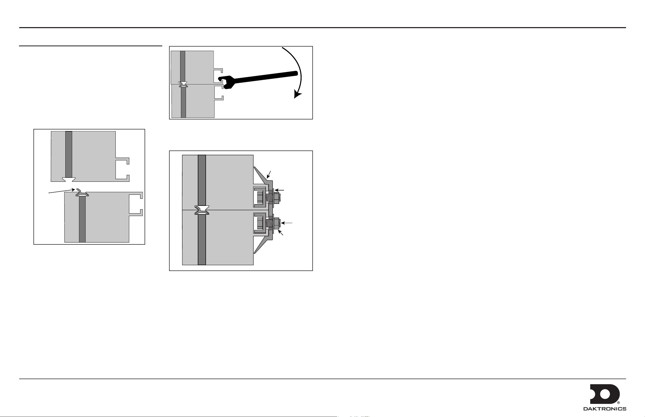
Section Splice Instructions
Refer to Section 4 of display manual for additional
information.
Due to size, some displays ship in multiple sections. A
sectional display consists of multiple sections to form a single
display face.
Note: Section splicing can be completed at ground level if the
display is no more than two sections tall.
1. Ensure splice key is in channel on bottom section.
6. Use splice wrench to draw sections together.
7. Connect splice plates and splice T-clips to both sections.
8. Tighten all nuts on all splice plates and splice T-clips.
Splice
Plate
Top
Display Face
Section
2. Attach crane to top section.
3. Unbolt top section from truck.
4. Lift top section and spin 180 degrees.
5. Lower top section until splice key engages.
Bolt
Bottom
Section
9. Refer to Step 1: Display Mounting on reverse side.
Nut
DD1931894 Rev 05
21 October 2014
PO Box 5128 201 Daktronics Drive, Brookings, SD 57006-5128
tel: 800-325-8766 fax: 605-697-4700
www.daktronics.com
 Loading...