

Page 1

Rear-Ventilated GalaxyPro® GP3 Series
Installation and Operation Manual
DD1931807 Rev 7 – 14 February 2013
201 Daktronics Dr. PO Box 5128 Brookings SD 57006
Tel 866-343-3122 Fax 605-697-4700
www.daktronics.com
Page 2

DD1931807
Product 1630
Rev 7 – 14 February 2013
DAKTRONICS, INC.
Copyright 2011 – 2013
All rights reserved. While every precaution has been taken in the preparation of this manual, the publisher assumes
no responsibility for errors or omissions. No part of this book covered by the copyrights hereon may be reproduced
or copied in any form or by any means – graphic, electronic, or mechanical, including photocopying, taping, or
information storage and retrieval systems – without written permission of the publisher.
GalaxyPro®, and Venus® are trademarks of Daktronics, Inc. Windows®, Explorer®, and Silverlight™ are trademarks of Microsoft® Corporation.
Java™ is a trademark of Oracle Corporation. All other trademarks are the property of their respective companies
Page 3

Table of Contents
Section 1: Introduction .......................................................................................................................1
1.1 Limitation of Liability .....................................................................................................................1
1.2 Contact Information ........................................................................................................................1
1.3 Model Number Guide ...................................................................................................................1
Section 2: Installation Preparation ....................................................................................................3
2.1 Pre-Installation Checklist ...............................................................................................................3
2.2 Structure Requirements ..................................................................................................................3
2.3 Electrical Requirements ..................................................................................................................3
Main Disconnect .......................................................................................................................4
2.4 Required Tools .................................................................................................................................4
Section 3: Display Installation ..........................................................................................................5
3.1 Display Installation .........................................................................................................................5
Section 4: Section Splicing ................................................................................................................7
4.1 Display Section Numbering...........................................................................................................7
4.2 Section Splicing Instructions..........................................................................................................7
Section 5: Electrical Installation ........................................................................................................9
5.1 Power Connection ...........................................................................................................................9
5.2 Earth Ground Installation ............................................................................................................10
Section 6: System Start-Up Procedure ...........................................................................................11
6.1 Boot Sequence ................................................................................................................................11
6.2 Start-Up Checklist .........................................................................................................................11
Section 7: Signal Cable Installation ................................................................................................13
7.1 Primary-Mirror Signal Connection .............................................................................................13
7.2 Sectional Display Signal Connections ........................................................................................13
Section 8: Network and Communication Installation ....................................................................15
8.1 Network and Communication Installation Dos .......................................................................15
8.2 Requirements For Communication Through A Network ......................................................15
8.3 Connecting To A Network And Using A DHCP Name ..........................................................15
Network Requirements .........................................................................................................15
Installation/Start-up Steps ...................................................................................................15
Table of Contents
i
Page 4

8.4 Connecting To A DHCP Network And Using A Static IP Address ......................................16
Network Requirements .........................................................................................................16
Conguration Steps ...............................................................................................................16
8.5 Connecting To A Network And Using A Static IP Address ...................................................16
Network Requirements .........................................................................................................17
Conguration Steps ...............................................................................................................17
8.6 Connecting To A Computer Using A Static IP Address..........................................................17
Requirements ..........................................................................................................................17
Conguration Steps ...............................................................................................................18
8.7 Standard Communication Options .............................................................................................18
Section 9: Venus
®
1500 Software Conguration ............................................................................19
9.1 Software Installation .....................................................................................................................19
9.2 System Requirements ...................................................................................................................19
9.3 Software Conguration ................................................................................................................19
Section 10: Display Maintenance ......................................................................................................21
10.1 Internal Display Access ................................................................................................................21
10.2 Ventilation System ........................................................................................................................22
Filter Inspection, Cleaning, and Replacement ...................................................................22
Fans ..........................................................................................................................................22
10.3 Display Face Cleaning ..................................................................................................................22
Wet Cleaning Process ............................................................................................................22
Dry Cleaning Process ............................................................................................................23
Section 11: Display Troubleshooting ................................................................................................25
11.1 Power and Signal Routing ...........................................................................................................25
Power Routing ........................................................................................................................25
Signal Routing ........................................................................................................................26
11.2 Player Diagnostics .........................................................................................................................27
11.3 PLR Diagnostics ............................................................................................................................27
PLR Self-Test ...........................................................................................................................27
11.4 Module and Power Supply Diagnostics ....................................................................................28
Module Self-Test ....................................................................................................................28
Section 12: Replacement Parts List .................................................................................................29
Section 13: Replacing Parts ..............................................................................................................31
13.1 Module and Power Supply Replacement ..................................................................................31
13.2 Player Replacement.......................................................................................................................31
13.3 PLR Replacement ..........................................................................................................................32
ii
Table of Contents
Page 5

Section 14: Daktronics Exchange and Repair & Return Programs ...............................................33
14.1 Exchange Program ........................................................................................................................33
Before Contacting Daktronics ..............................................................................................33
14.2 Repair & Return Program ............................................................................................................34
Shipping Address...................................................................................................................34
14.3 Daktronics Warranty and Limitation of Liability .....................................................................34
Appendix A: Reference Drawings .......................................................................................................35
Appendix B: Daktronics Warranty and Limitation of Liability ..........................................................37
Table of Contents
iii
Page 6
Section 1: Introduction
This manual provides the necessary information to install and service a GalaxyPro® GP3 series display.
Please read and understand all steps in this manual before beginning the installation process.
For a smooth installation, complete the steps in this manual in order. Contact Daktronics Technical
Support with any questions before or during the installation process.
1.1 Limitation of Liability
The factory warranty will be nullied if:
• The display is not installed according to the steps in this manual
• Proper electrical service is not provided or the display is not grounded properly
• Unauthorized modications are made to the display, display cabinet, or the control
system
Refer to AppendixB at the end of this manual for the full Daktronics Warranty and Limitation of
Liability.
1.2 Contact Information
For assistance before, during, or after display installation, please contact Daktronics Technical
Support: 800-DAKTRONICS (800-325-8766).
1.3 Model Number Guide
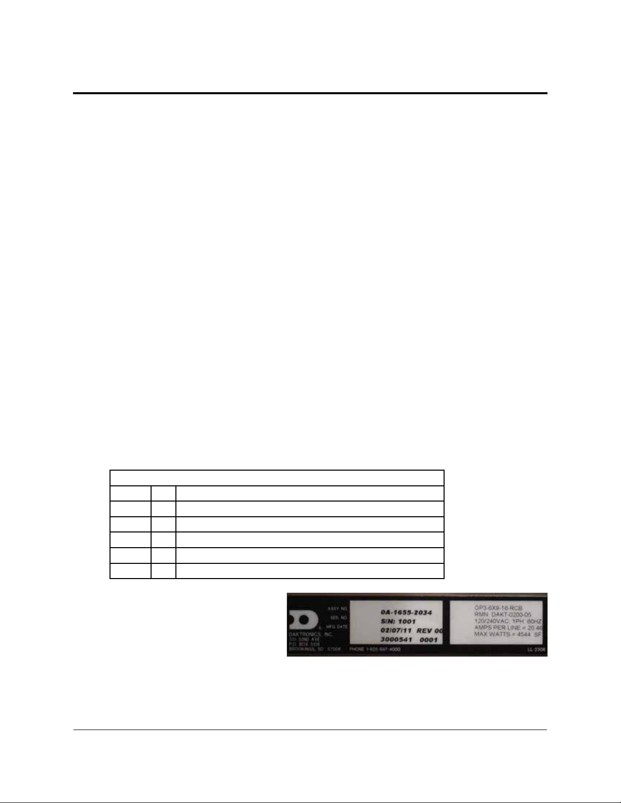
GalaxyPro® GP3 model numbers are dened as follows:
GP3-RxC-M-RGB-F
GP3
R
C
M
RGB
F
Figure1 shows a label on the display’s
back where the model number and
power requirements are located.
Displays are either single face (SF) or
two view (2V). In 2V units, the rst
display is referred to as the primary
and the second is called the mirror. If the second display is mounted more than 15 feet (4.5 m)
from the primary display, two primary displays are used.
= Outdoor GalaxyPro® display
= Number of pixel rows high
= Number of pixel columns long
= Pixel pitch in millimeters
= LED Color: R (Red), G (Green), B (blue)
= Face setup: SF – Single Face or 2V – Primary/Mirror
Figure 1: Display Label
Introduction
1
Page 7

A typical display system consists of a Windows
®
-based computer running Venus® 1500 software
and one or more displays. The Venus® 1500 software package runs on an IBM®-compatible
computer. Refer to the Venus®1500softwarehelple for operation instructions.
2
Introduction
Page 8

Section 2: Installation Preparation
This section explains what to consider before installing a Daktronics GalaxyPro® GP3 display.
Follow all guidelines and safety precautions in this manual when installing the display. Do not modify
the display or control system in any manner without the written permission of Daktronics’ engineering
staff.
Any unauthorized modications will nullify the display warranty.
2.1 Pre-Installation Checklist
• The display was not damaged during shipping
• The mounting structure will provide a straight and square mounting frame for the display
• The support structure can carry the weight of the display and meets local and national codes
• There is clearance at the back of the display to allow unobstructed airow – refer to shop
drawing for ventilation specications
• Ensure proper power is available at sign structure – refer to shop drawing for display power
requirements
• The display cabinet has no holes (accidental or intentional) that will allow water to enter the
display
• All display modules are fully latched into the display cabinet
2.2 Structure Requirements
Support structure design depends on mounting method, installation height, display size, and
weight. Because every installation site is unique, Daktronics approves no single procedure for
mounting displays.
Things to consider prior to installation:
• Display structure and mounting must not obstruct airow - refer to shop drawing for
ventilation space requirements
• All T-clips must be used for mounting to structure
• Light sensor must not be obstructed to maintain proper display dimming
For additional questions about display mounting requirements and specications, refer to the
display shop drawing or contact Daktronics Technical Support at 800-DAKTRONICS (800-325-
8766).
2.3 Electrical Requirements
ImportantNote: Size circuits according to local and national codes so the power distribution
system delivers full-load power to the display while maintaining a voltage within 5 percent of the
nominal voltage.
Installation Preparation
3
Page 9

Main Disconnect
Daktronics requires installation of a power disconnect switch with the display so all ungrounded
conductors can be disconnected near the point of power connection.
2.4 Required Tools
The following table lists the minimum tools Daktronics recommends having on site for each
installation. Daktronics only provides the specialized tools needed to complete the installation.
Daktronics Provided Customer Provided
Splice Wrench Hex Head Wrenches – 1/8” and 3/16”
Flathead and Phillips Head Screw Drivers
Crane or Lift Truck
Step Ladders
®
Computer with Venus
Ratchet and/or Impact Wrench –
Socket Set – Sizes up to 1
Tape Measure
Utility Knife
1500 Software and Internet Explorer® Installed
11
/16”
1
/16” Needed
4 Installation Preparation
Page 10
Section 3: Display Installation
This section explains the steps necessary for proper lifting and installation of the display to the sign
structure.
Follow all guidelines and safety precautions in this manual when installing the display.
Do not modify the display or control system in any manner without the written permission of Daktronics’
engineering staff. Any unauthorized modications will nullify the warranty.
Display Installation Dos
• Inspect the display for damage prior to installation
• Use all T-clips for mounting
• Provide an adequate support structure that is straight and level
• Provide adequate ventilation that meets or exceeds display specications.
Note: Shrouding may be used, but proper ventilation must be placed into the shrouding.
• Use all lift eyes when lifting the display
• Install all splice plates and splice T-clips when applicable
Display Installation Don’ts
• Drill holes into the display
• Block display ventilation system
• Use the lift eyes for display mounting
• Move clip angles outside the designated zones indicated by label
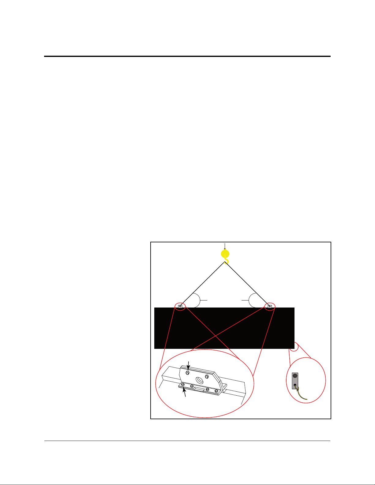
3.1 Display Installation
1. Use a utility knife to
carefully cut away all
of the white packaging
material from the display.
Be careful not to damage
the face of the display or
LEDs.
2. If the display is multi-
sectional, refer to Section
4 before continuing.
3. Attach a crane or lift
truck to the lift eyes on
the display’s top.
Note: Lift eye spacing
is set at Daktronics and
should not be moved.
Lift eyes should also
remain in place after
installation is complete.
Angle must be
greater than 55°
Lift-Eye Bolts
From Back
Tag Line
Tie Off
Set Bolts
Figure 2: Proper Display Lifting
Display Installation
5
Page 11
Note: Ensure the angle between the top of the display and the lifting strap is greater than 55
degrees, as shown in Figure2.
4. Apply tension to the lift lines.
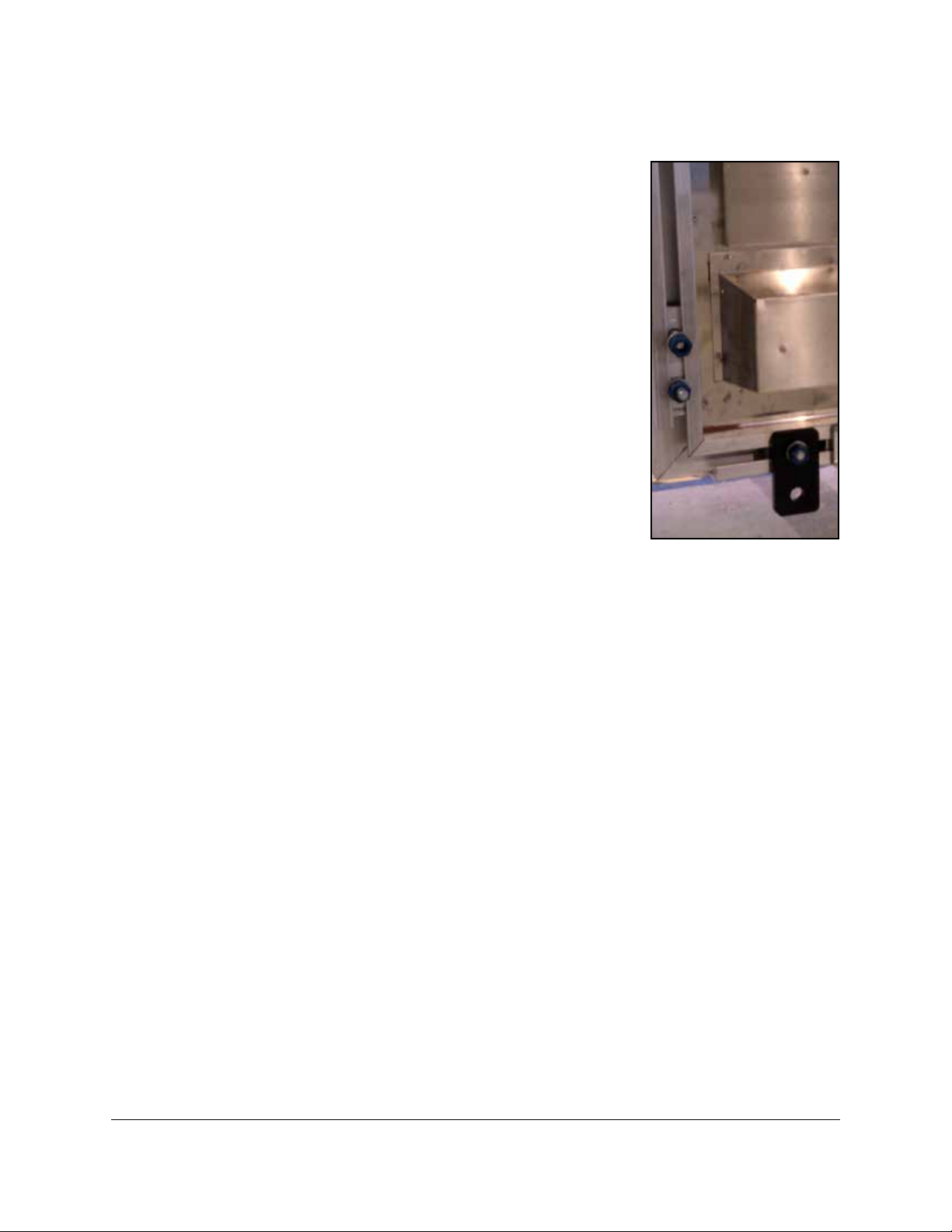
5. Attach tag lines to the bracket shown in
Figure3.
6. Unbolt the display from the shipping braces.
7. Lift the display off the truck to the display structure.
Note: Do not lift displays in wind speeds greater than 20 mph.
8. Mount the display to the structure by welding or bolting all
T-Clips to horizontal stringers.
Note: Use all T-Clips when mounting the display.
Note: The T-Clips are installed in the recommended locations
at Daktronics, but can be moved 12 inches either way to avoid
obstructions. Refer to the label on the display for limitations.
9. Remove crane support and tag lines from the display once
mounting is complete.
Figure 3: Tag Line Bracket
10. Locate the top border caps and install over lift eyes using
provided Tek screws.
6 Display Installation
Page 12
Section 4: Section Splicing
4.1 Display Section Numbering
For multiple-section displays, each section is numbered for
easy identication. In a two-section display, shown in Figure
4, the top section is 101 and the bottom section is 201.
In four-section displays, shown in Figure5, the upper-left
display section is 101 and the section to the right is 102; the
second row of sections is 201 on the left and 202 on the right.
Note: Left and Right sections are pre-assembled prior to
shipping for displays up to 48 feet wide.
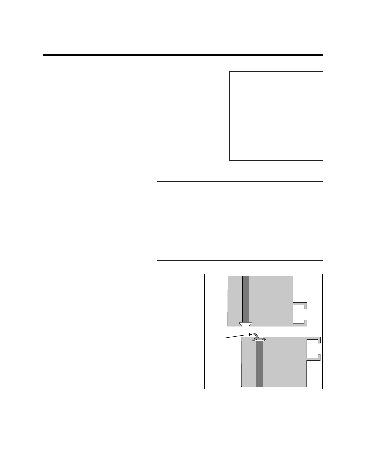
4.2 Section Splicing Instructions
1. Ensure the splice key is
inserted in the channel of the
bottom section, as shown in
Figure6.
2. Attach a crane or lift truck
to the lift eyes of the top
section and apply tension.
3. Unbolt the top section of the
display from the truck bed
and unbolt A-frame.
Figure 5: Four-Section Display Section Numbers
Section 101
Section 201
Section 101
Section 201
Figure 4: Two-Section Display Section
Numbers
Section 102
Section 202
4. Lift the display top section off the truck high
enough to spin around 180 degrees.
Section Splicing
Top
Section
Splice
Key
Bottom
Section
Figure 6: Splice Key In Channel
7
Page 13
5. Slowly lower the top section until it rests on the bottom section with the splice key engaged.
Top
Section
Bottom
Section
Splice
6. Starting at one end of
the display, use the
splice tool to draw the
top section into the
bottom until the splice
key is fully engaged, as
shown in Figure7.
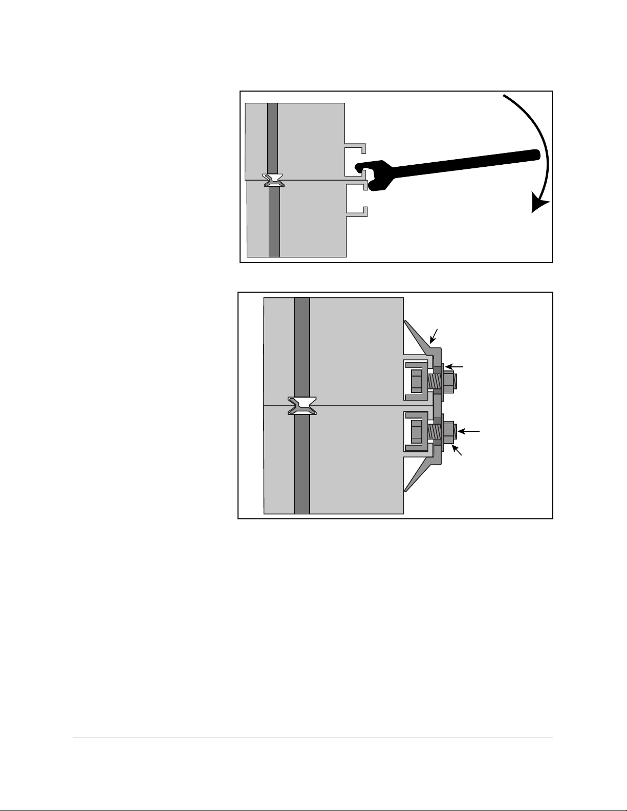
7. Ensure display
sections are aligned
and that LEDs are also
in alignment.
8. Attach the splice plates
and splice T-clips
along the section
splice, as shown in
Figure8. Use an
11
/16”impact wrench or
ratchet to tighten all
nuts on the splice
plates and splice
T-clips.
Figure 7: Pull Display Sections Flush
Top
Display Face
Section
Bottom
Section
Figure 8: Attach Splice Plates and T-clips.
Plate
Washer
Bolt
Nut
8
Section Splicing
Page 14

Section 5: Electrical Installation
This section explains the steps necessary to make nal electrical connections to the display from the
primary power source. For display-specic power requirements, refer to the shop drawing or label on the
display’s back.
Electrical Installation Dos
• Follow all installation guidelines
• Route power to the display through a disconnect switch
• Provide the required power per display requirements
• Provide a separate circuit for each display
• Connect each display face to a dedicated earth-ground electrode
• Follow all local and national electrical codes
Electrical Installation Don’ts
• Share circuits between displays and other electrical devices
• Connect the display to any voltage other than that listed on the product label
• Connect the neutral to the ground at the disconnect or the display
• Use the display support structure as an earth-ground electrode
5.1 Power Connection
1. Review the power requirements for the
display. Requirements are found on the
display shop drawing or label on the
display’s back, as shown in Figure9.
2. Route conduit from the main distribution
panel/disconnect to each display power
entrance. Each display section has a power
entrance and requires a dedicated circuit.
3. Remove the four screws that attach the
power entrance access door.
4. Connect conduit to the 2” Myers hub at
the left of the power entrance box.
5. Feed power cable from the conduit into
the power entrance box.
6. Connect the power ground wire to the
appropriate tap (green wire), as shown in
Figure10.
Note: Use a 3/16” hex head wrench to
tighten screws that hold wires in place.
Figure 9: Display Power Requirements Label
Figure 10: Power Entrance Box
Electrical Installation
9
Page 15

7. Connect power line 1 (L1) to the appropriate tap (black tape on cable).
Primary
Mirror
Display
Ground Lug
Thermal Weld
Connection
Preferred
Conduit
Copper Ground Conductor
(One Per Display Face)
Copper Ground Rods
8 ft.(2.5 m)
min.
8 ft.(2.5 m)
min.
8. Connect power line 2 (L2) to the appropriate tap (red tape on cable).
9. Connect the neutral to the appropriate tap (white tape on cable).
10. Reinstall the power enclosure cover using all four screws.
5.2 Earth Ground Installation
Daktronics GalaxyPro® GP3 displays require a resistance to ground of 10 ohms or less. Follow the
steps below to connect the display to an earth-ground electrode and measure the resistance to
ground.
1. Install an earth-ground
electrode (ground rod,
ground plate, etc.) near the
base of the display. Refer
to Figure11 for guidelines.
Note: Each display face
requires an earth-ground
electrode.
2. Connect a copper wire
from the grounding
electrode to the ground
lug on the back of the
display.
Figure 11: Proper Display Grounding
3. Using an Earth Ground Clamp Meter, shown in Figure12, measure the resistance to
ground near the grounding electrode. If the reading is greater than 10 ohms, install
additional grounding electrodes.
4. Bury any copper cable or grounding electrodes so they are
below grade.
Importantpointsaboutgrounding:
• Followlocalandnationalcodes:The material of an earth-
ground electrode differs from region to region and from
conditions present at site. Consult any electrical codes that
apply.
• Supportstructurecannotbeusedasanearth-ground
electrode: The support structure is generally embedded
in concrete, and if embedded in earth, the steel is either
primed or it corrodes, making it a poor ground.
• Onegroundingelectrodeforeachdisplayface
Figure 12: Measure
Resistance to Ground
10
Electrical Installation
Page 16

Section 6: System Start-Up Procedure
Displays show a boot sequence about two minutes after power is turned. This information is very useful
when conguring the display in Venus® 1500 software. Prior to turning the display on, make sure display
communications and any network connections have been made.
6.1 Boot Sequence
Description
Firmware Name and Version
Display Size (Pixels High by Pixels Wide)
DHCP Name Assigned
IP Address and State
MAC Address
Conguration Port
Status Port
Management Port (Used to Access Conguration)
Description
6.2 Start-Up Checklist
• Conrm power is correctly connected to the display
• Conrm there is sufcient power according to display requirements
• Conrm a main disconnect is installed
• Conrm the display is connected to an earth-ground electrode with a resistance of 10 ohms or
less
• Conrm that all communication equipment is installed according to provided documentation
• Conrm that any necessary network connections have been made
• Conrm the control computer has Venus® 1500 software installed
• Inspect peripheral equipment (temperature sensor, light sensor, etc.) for proper installation
System Start-Up Procedure
11
Page 17

Page 18

Section 7: Signal Cable Installation
This section describes signal cable installation for GalaxyPro® GP3 series displays. There are several types
of data signal connections that may need to be made depending on the size of the display and number of
sections.
7.1 Primary-Mirror Signal Connection
For data to get from the Primary display to the Mirror display, the ber interconnect cable must
be connected. This cable typically comes attached to the back of the display.
1. Locate cable and unpackage.
2. Connect one end of the cable to J34 on the
back of the Primary display, as shown in
Figure13.
3. Connect the other end of the cable to J32 on
the back of the Mirror display.
4. Coil up any excess cable and secure it to
prevent vandalism and weather-related
damage.
Note: Anchor points are found on each fan
hood for securing excess cable.
Figure 13: Signal Out Quick-Connect Jack
7.2 Sectional Display Signal Connections
For sectional displays, data is transmitted from one
section to the next through ber cables connected to the
outside of each section.
Each section has multiple jacks labeled either A or B.
Refer to drawing B-1033700 in the back of this manual for
correct cable routing between display sections. A label
on the display’s back also illustrates how to connect the
cables. An example of this label is shown in Figure14.
Figure 14: Example Cable Connection
Label on Back of Display
Signal Cable Installation
13
Page 19

Page 20

Section 8: Network and Communication Installation
This section explains how to setup communications with a GalaxyPro® GP3 series display through a
network or an individual computer. Obtain information about the available standard communication
options in the provided quick guides and reference manuals.
Daktronics is not responsible for setting up displays on a Wide Area Network (WAN), but can assist with
setting up communication on a Local Area Network (LAN) or directly to a personal computer.
8.1 Network and Communication Installation Dos
• Complete all network and communication installation prior to turning display on
• Have a laptop on site with Internet access (preferred)
• Work with the Customer’s IT professional for network integration
Daktronics GalaxyPro® GP3 series displays use DHCP by default, which allows automatic display
conguration by the customer’s network, and eliminates manual conguration of the player.
When the display is connected to a network that supports DHCP, a default DHCP name similar
to ‘DAKTxxxxxx’, where ‘xxxxxx’ represents the last 6 digits of the player’s MAC address, is
used. This information is shown in the display boot sequence.
8.2 Requirements For Communication Through A Network
• Ports 4500-4525 must be open for communication on the switch or router
8.3 Connecting To A Network And Using A DHCP Name
The following steps explain how to congure a display and connect to a network that supports
DHCP and using the display’s DHCP name is desired for communication.
Network Requirements
• DHCP Server
• Existing Network
• Available network port, congured properly
• PC with Venus 1500 software installed
Installation/Start-up Steps
1. Make sure computer with Venus 1500 software installed is turned on.
2. Ensure computer has an established link with the network.
3. Turn display on.
Network and Communication Installation
15
Page 21

8.4 Connecting To A DHCP Network And Using A Static IP Address
The following steps explain how to congure a display when it is connected to a network that
supports DHCP, but a static IP address is desired for the display.
Network Requirements
• Existing Network
• Available network port, congured properly
• PC with Venus 1500 software installed
• Static IP information (provided by customer)
Conguration Steps
1. Connect a computer to the display setup for ObtainIPaddressautomatically.
2. Turn display on.
3. Launch DisplayFind and discover the display.
4. Once the display is found, click the link to launch the conguration utility.
5. Click Logon to connect to the display (refer to the help le for additional information about
the conguration utility).
6. Congure the IP settings.
7. Click UploadConguration.
8. Log out of the conguration utility.
9. Turn display off.
10. Disconnect the computer from the display and connect display to the network.
11. Make sure computer with Venus 1500 software installed is turned on.
12. Ensure computer has an established link with the network.
13. Turn display on.
14. Congure the display in Venus 1500.
8.5 Connecting To A Network And Using A Static IP Address
The following steps explain how to congure a display when it is connected to a network that
does not support DHCP.
16
Network and Communication Installation
Page 22

Network Requirements
• Existing network
• PC with Venus 1500 software installed
• Static IP information (provided by customer)
• Available network port, congured properly
Conguration Steps
1. Write down the IP address on the computer with Venus 1500 software installed.
2. Change the IP address to ObtainAutomatically.
3. Allow computer to fail over to DHCP – process may take up to 3 minutes.
4. Turn display on.
5. Launch DisplayFind and discover the display.
6. Once the display is found, click the link to launch the conguration utility.
7. Click Logon to connect to the display (refer to the help le for additional information about
the conguration utility).
8. Congure the IP settings.
9. Click UploadConguration.
10. Logout of the conguration utility.
11. Turn display off.
12. Change the computer’s IP address back (written down in step 1).
13. Turn display on.
14. Congure display in Venus 1500 software.
8.6 Connecting To A Computer Using A Static IP Address
When connecting a display to a computer and not a network, it is recommended to use the USBto-Ethernet adapter. This allows the computer to maintain any Internet or network connections
while still being able to control the display.
Requirements
• PC with Venus 1500 software installed
• USB-to-Ethernet adapter
Network and Communication Installation
17
Page 23

Conguration Steps
1. Install USB-to-Ethernet adapter driver on computer.
2. Establish a link between the adapter and the display.
3. Turn display on.
4. Launch DisplayFind and discover the display.
5. Once the display is found, click the link to launch the conguration utility.
6. Click Logon to connect to the display (refer to the help le for additional information about
the conguration utility).
7. Congure the displays IP address to:
IP Address: 172.16.192.25
Subnet Mask: 255.255.0.0
8. Click UploadConguration.
9. Log out of the conguration utility.
10. Turn display off.
11. Congure IP address on USB-to-Ethernet adapter to:
IP Address: 172.16.192.20
Subnet Mask: 255.255.0.0
12. Turn display on.
13. Congure display in Venus 1500 software.
8.7 Standard Communication Options
Daktronics GalaxyPro® GP3 displays can receive various forms of Ethernet communication.
The standard communication options are listed below along with the communication-specic
document numbers. For additional information regarding communication installation, refer to
these documents, which are provided with the communication kits.
Communication Type Manual Document Number Quick Guide Document Number
Ethernet – Wire DD1417609 DD1417573
Ethernet – Fiber DD1417611 DD1417581
Ethernet Bridge Radio DD1685027 DD1417586
These are the standard communication types, but each site is unique and may include additional
equipment. For questions, contact Daktronics Technical Support.
18 Network and Communication Installation
Page 24

Section 9: Venus® 1500 Software Conguration
Other control software is available on a contract basis. Refer to that product’s help le for system
requirements, installation, and conguration information.
9.1 Software Installation
Venus® 1500 is the standard control software for GalaxyPro® GP3 displays. Install Venus® 1500
software either from a disc or from www.daktronics.com\venus1500. Click the Downloads tab
and Venus1500setup.exe. Venus® 1500 requires registration which must be completed within 90
days of installation. Refer to the Venus®1500HelpFile for registration instructions.
9.2 System Requirements
Minimum System Requirements
Windows XP®, Vista®, or 7® with current updates
applied (32-or 64-bit versions)
800 Mhz or higher Processor 1.6 GHz or higher Processor
512 MB RAM or higher 1.5 GB RAM or higher
1 GB of Free Hard Disk space (additional space
required for content storage)
Monitor and video adapter capable of 1024x768 or
higher resolution with DirectX
Microsoft Internet Explorer
.NET 3.5 Framework Service Pack 1 .NET 3.5 Framework Service Pack 1
CD-ROM or DVD drive CD-ROM or DVD drive
Keyboard and Mouse or other compatible pointing
device
®
9 support
®
7 or higher Microsoft Internet Explorer® 7 or higher
9.3 Software Conguration
Ensure all display communications and network connections are made before conguring a
display in Venus® 1500 software. Once everything is installed, turn the display on, allow it to
complete the boot sequence, then follow the steps below.
1. Click the Windows® Start
button. Hover over All
Programs>Daktronics
>Venus1500V4. Click
Venus1500.
Recommended System Requirements
Windows XP®, Vista®, or 7® with current updates
applied (32-or 64-bit versions)
1 GB of Free Hard Disk space (additional space
required for content storage)
Monitor and video adapter capable of 1280x1024 or
higher resolution with DirectX® 9 support
Keyboard and Mouse or other compatible pointing
device
2. Click the Application
button, highlight
Congure, click Displays,
as shown in Figure15.
Venus 1500 Software Conguration
Figure 15: Begin Display Conguration
19
Page 25

3. Click AddDisplay...
from the Display
Management window. Or
right-click in the Display
Management window and
select AddDisplay..., as
shown in Figure16.
4. The software searches for
displays on the local
network and returns a list
Figure 16: Congure a New Display
of displays it nds.
5. Select the display you wish to
congure and click Continue,
as shown in Figure17.
Note: If the display is password
protected, enter the password
on the AuthenticationPage.
Note: Save the password in a
secure location. Physical access
to the display is required to
reset the password if it is lost.
6. Give the display an easy-to-
identify name when the Display
Found prompt opens. This
Figure 17: Displays Found List
prompt also provides a brief
description of the display. Click Continue.
Note: If the display is not
found, refer to the Venus
1500HelpFilefor manual
conguration instructions.
7. Select the correct time zone
for the display’s location.
Greenwich Meantime,
along with country and
city or region are the
guides used to select the
correct time zone.
8. A Summary box, shown
in Figure18, provides
basic information about
the newly congured
Figure 18: Display Conguration Summary Window
display. Click BacktoStart
to return to the beginning of the process to congure another display. Click Finish to
complete display conguration.
20
Venus 1500 Software Conguration
Page 26

Section 10: Display Maintenance
This section explains the steps necessary
to maintain the GalaxyPro® GP3 display.
Daktronics GalaxyPro® GP3 displays
are front accessible. Remove modules
on the front of the display to gain access
to internal components. Figure19 and
Figure22 show internal component
locations.
ImportantNotes: Turn OFF power before
any repair or maintenance work is done
on the display.
10.1 Internal Display
Access
1. Disconnect power to the
display.
2. Locate the two access holes to
gain access to the quarter-turn fasteners
on the module.
Fans
Thermostat
Player
Power
Supply
PLR
Light
Sensor
Figure 19: Component Locations In Lower Left of Display
Player
Enclosure
Filter
Power
Termination
Panel
3. Using a 1/8” hex head wrench, turn each latch a
quarter turn
counterclockwise.
4. Gently pull
the module
far enough
forward
to reach
behind and
disconnect
the power
and signal
cables.
Note: Do not
allow module
to hang by its
cables. Doing
so causes
Figure 20: Lanyard Attachment Top
View
Figure 21: Module Attached To Lanyard
irreversible
damage to the module. Use the provided lanyards to hang a module, as shown in Figure20
and Figure21.
Display Maintenance
21
Page 27

5. When ready to reinstall the module, reconnect the cables, push the cables into the display so
they do not get pinched and latch the module using a
Note: A fully seated module should be ush with the modules around it.
10.2 Ventilation System
GalaxyPro® GP3 displays are equipped with a ventilation system that helps keep internal
components at operable temperatures. GalaxyPro® GP3 displays are rear ventilated, so the
display support structure must allow adequate space or air movement for proper ventilation.
Refer to the display shop drawing for ventilation requirements.
Filter Inspection, Cleaning, and Replacement
The ventilation system includes lters that prevent dirt and debris from entering the display
cabinet. Check and replace lters regularly to ensure adequate air ow in the display. At
a minimum, check lters every six months, but more frequent inspection may be required
depending on conditions around the display.
Clean lters with water or compressed air (no greater than 60psi and at least 6” away) blown
through the lter in the opposite direction from which air normally ows. Allow lters to dry
before returning them to their trays. Again, Daktronics encourages users and service technicians
to use their own discretion when deciding whether to clean or replace the lters.
1
/8” hex head wrench.
Fans
Fans help bring fresh air into the display while exhausting hot air through the upper vents. Fans
are controlled via a thermostat in the display cabinet. The thermostat is equipped with a bypass
button for testing fan operation. Replace fans that are not working properly.
10.3 Display Face Cleaning
Wet Cleaning Process
1. Turn off power to the display.
2. Mix a mild, non-abrasive, non-petroleum-based detergent and cold water, one ounce of
detergent to one gallon of cold water.
3. Saturate a light/medium duty cleaning brush with the soapy water.
4. Use horizontal brush strokes to loosen and remove dirt and grime, washing the display from
top to bottom. Use light pressure so as not to damage the LEDs. Clean only an area that is
safely within reach from a lift or stage, and then move on to the next section of modules.
5. Rinse the display face with generous amounts of cold water under low pressure. A spot-free
rinse agent can be used to reduce water spots.
22
Display Maintenance
Page 28

6. Use soft, dry terrycloth to dry and remove any excess water. Take care not to damage LEDs
by catching the cloth on them.
7. Allow the display to completely air-dry for 12 hours before applying power to the display.
Dry Cleaning Process
1. Turn off power to the display.
2. Rub a dry, soft terrycloth towel horizontally across each row of LEDs. Make four passes per
row of LEDs before moving to the next row of LEDs. Work from top to bottom safely within
reach from a lift or a stage. Take care not to damage LEDs or the plastic louvers by catching
the cloth on them.
Display Maintenance
23
Page 29

Page 30

Section 11: Display Troubleshooting
This section provides basic display information such as power and signal routing as well as basic
troubleshooting tips for common problems. For issues not addressed in this manual, please contact
Daktronics Technical Support.
11.1 Power and Signal Routing
Understanding power
and signal ow through
the display can help a
technician troubleshoot
an issue.
Power Routing
Figure22 shows how
power is routed through
the display.
1. AC Power enters
the display
through the
power entrance
box on the back
of the display
and travels
to the Power
Termination
Panel.
Player
Module
Power
Supply
Light
Sensor
Module
Power
Supply
(one on
every
module)
Power
Supply
3
PLR
4
Figure 22: Power Routing
Player
Enclosure
2a
2b
Fans
Thermostat
2d
2c
Power
Termination
Panel
Filter
1
2. Power is
distributed to Module Power Supplies (2a), Player Power Supply (2b), Thermostat (2c),
and Fans (2d).
Note: Each module has its own Module Power Supply attached to the back of the
module.
3. DC Power is supplied to the Player (3) from the Player Power Supply.
4. DC Power is also supplied to the PLR (4) from the PLR power jack on the back of the
module.
Display Troubleshooting
25
Page 31

Signal Routing
Figure23 shows how signal is routed through the display.
1. Signal enters
2b
2c
4b
2d
the display
from the
external
signal
enclosure
4a
through
the signal
input quickconnect jacks
(1).
5
2. Signal travels
from the J32
signal input
jack through
an Ethernet
Figure 23: Signal Routing
Cat5e cable
to the J32
Ethernet jack on the player (2a)
4c
3
2a
1
4b
5
6
• The J33 auxiliary input jack is connected to the J33 jack on the player (2b).
• The temperature sensor is connected to the J31 input quick-connect jack. From
the J31 quick-connect jack it is connected to the J31 jack on the player (2c).
• The light sensor is connected to the J35 input quick-connect jack. From the J35
quick-connect jack it is connected the J35 jack on the player (2d).
3. Signal travels from the player from Fiber A to the PLR Port A (3).
4. From SATA A on the PLR, signal goes to the rst module (4a) and travels from module
to module via SATA cables (4b), nally returning to the PLR to SATA B (4c).
5. Signal leaves the PLR from Fiber B and travels to the Output Fiber Quick Connect (5).
6. Signal from the primary display face Output Fiber Quick Connect travels to the mirror
face (6) to jack J32.
26 Display Troubleshooting
Page 32

11.2 Player Diagnostics
1
2
3
4
5
6
7
8
C
D
E
F
9
A
B
0
DMP-4060 is the player in a
GalaxyPro® GP3 display. The
player is located in the lowerleft portion of the display in an
environmental enclosure. The
player receives incoming signal
from the control computer and
routes that signal to the ProLink
Router (PLR). The player has
several LEDs on it that can be
useful when troubleshooting a
communication issue. Figure24
explains those LEDs.
11.3 PLR Diagnostics
The ProLink Router (PLR),
receives signal from the display
player, which transfers it on
to the modules through SATA
cables. GalaxyPro® GP3 displays
are equipped with a redundant
signal path, meaning two SATA
cables are connected to each
module. If one of the two SATA
cables fail, the module continues
to receive data from the other SATA cable and the display continues functioning normally.
INDICATORS
RUN-Flashes
during
operation
ETH0 1000MB
ETH0 100MB
ETH0 10MB
ETH0-ON
Full Duplex
ETH1 1000MB
ETH1 100MB
ETH1 10MB
ETH1-ON
Full Duplex
ETHERNET
Hardware link
flashes during
TX comm.
Flashes during
RX comm.
Figure 24: Controller Diagnostic LEDs
PLR Self-Test
When put into self-test mode, the PLR tests
for correct operation and displays pass/fail
status on the 7-segment display.
To put the PLR into self-test mode, loop a
SATA cable between ports A and B. Then
take a ber cable and connect the ber
ports together, as shown in Figure25. Once
the cables are connected, cycle power to
the PLR and it will boot-up in self-test
mode. Following is a table of a few possible
messages. Contact Daktronics Technical
Support for additional information or
questions.
Display Troubleshooting
Figure 25: PLR Self-Test Setup
27
Page 33

Code Description
8 8 8 Testing 7 segments (held for 2 seconds)
t s t Initial test in progress (60-second duration)
P A S All tests passed
E r r Test failures reported
F 0 1 Fiber Port A Error
F 0 2 Fiber Port B Error
F 0 3 RJ45 IN (Port A) Error
F 0 4 RJ45 OUT (Port B) Error
F 0 5 ProLink5 (SATA) Port A Error
F 0 6 ProLink5 (SATA) Port B Error
If any Err message is displayed, send the PLR back to Daktronics for repair or replacement.
11.4 Module and Power Supply Diagnostics
Each module in a GalaxyPro® GP3 display has a power supply attached to it. Each power supply
provides power only to the module it is connected to. Display modules are equipped with a
status indicator LED that can help troubleshoot possible issues. Under normal operation, the
status indicator LED should ash once every 4 seconds.
Module Self-Test
If a module is blank, but has power supplied to it, perform a module self-test to diagnose a
module or SATA cable failure. To perform a self-test, follow the steps below.
1. Attach a SATA cable to Port A
and Port B on the module, as
shown in Figure26.
2. Disconnect the power to the
power supply for 10 seconds.
3. Reconnect the power to start
the self-test.
4. Verify the module is running a
self-test.
Remove the SATA cable and cycle
power to the module to stop the selftest.
Figure 26: Module Self-Test
28 Display Troubleshooting
Page 34

Section 12: Replacement Parts List
The following table contains some of the items that may need to be replaced over a period of time. All
GalaxyPro® GP3 displays ship with at least two spare modules
with power supplies and two spare SATA cables depending on
the size of the display.
0P-1127-0024
If a component is not listed in the replacement parts list, use the
label to order a replacement. Most components within displays
carry a label that lists the part number of the unit. A typical label
is shown in Figure27, with the part number in bold.
Part Number Description
0A-1576-7001 26 mm Module With Power Supply Attached
0A-1586-7001 20 mm Module With Power Supply Attached
0A-1621-7001 16 mm Module With Power Supply Attached
0A-1327-0300 DMP-4060 Controller Enclosure Assembly
0A-1487-6009 PLR Assembly
W-2094 SATA Cable, 2 Foot
W-1659 Fiber Cable
B-1045 Fan Assembly
0A-1327-1094 Quick Connect, Primary Input
0A-1327-1095 Quick Connect, Primary Output
0A-1327-1096 Quick Connect, Mirror Input
W-1658 Fiber-Optic Cable, 10 Foot
W-1685 Fiber-Optic Cable, 33 Foot
W-2030 Fiber-Optic Cable, 25 Foot
0A-1327-3105 Thermostat Assembly
0A-1327-3016 Light Sensor Assembly
SN: 2465
02/19/12 Rev. 1
Figure 27: Typical Parts Label
Replacement Parts List
29
Page 35

Page 36

Section 13: Replacing Parts
13.1 Module and Power Supply Replacement
Each module in a GalaxyPro® GP3 display has an attached power supply and is replaced as an
entire assembly.
Note: When removing modules from the display, do not allow them to hang by the cables.
Lanyards, shown in Figure20, are provided with the spare parts kit for hanging modules.
1. Turn off power to the display.
2. Remove module using a 1/8” hex head wrench.
3. Pull the module slightly out of the display.
4. Disconnect the power cable to the power supply.
5. Carefully disconnect the two SATA cables from the module.
6. Connect the two SATA cables to the new module.
7. Connect power to the power supply.
8. Reinsert the module making sure not to pinch any cables.
9. Latch the new module into place making sure it is fully seated.
13.2 Player Replacement
The player is located in the lower-left area of the display, as shown in Figure19. From the
bottom-left corner of the Primary face, go up to the second row of modules and over to the right
two modules to locate the player. The player is in an enclosure which is not to be opened. Replace
the entire enclosure.
1. Remove the modules in front of the player.
Note: Do not allow the modules to hang by their cables
2. Disconnect the cables at the bottom of the enclosure.
3. Loosen the four screws connecting the enclosure to the back of the display.
4. Carefully lift the enclosure up and out of the display.
5. Insert the new enclosure and tighten all four screws.
Replacing Parts
31
Page 37

6. Reattach the cables to the bottom of the enclosure using the label as a guide.
13.3 PLR Replacement
The PLR is located behind the second module up from the bottom in the rst column of modules,
as shown in Figure19. PLRs can be found in both Primary and Mirror display faces as well as all
sections of a sectional display.
1. Remove the module in front of the PLR.
Note: Do not allow module to hang by its cables.
Note: This module will likely have four cables attached as it provides power to the PLR.
2. Disconnect the two SATA cables and ber cables to the PLR.
3. Loosen the screw at the top of the PLR mounting plate.
4. Lift the mounting plate up and out of the display.
5. Insert the new PLR with mounting plate and tighten the screw.
6. Insert the two SATA cables and ber cables in the appropriate locations.
32
Replacing Parts
Page 38

Section 14: Daktronics Exchange and Repair &
Return Programs
14.1 Exchange Program
The Daktronics Exchange Program is a quick, economical service for replacing key components
in need of repair. If a component fails, Daktronics sends a replacement part to the customer who,
in turn, returns the failed component to Daktronics. This not only saves money but also decreases
equipment downtime. Customers who follow the program guidelines explained below will
receive this service.
Before Contacting Daktronics
Fill in these numbers before calling Customer Service:
Display Model Number: ________________________________________
Date Installed: ________________________________________________
Location of Display: ___________________________________________
Daktronics Customer ID Number: _______________________________
To participate in the Exchange Program, follow these steps:
7. Call Daktronics Customer Service: 866-343-3122.
8. When the new exchange part is received, mail the old part to Daktronics.
If the replacement part xes the problem, send in the problem part which is being
replaced.
a. Packagetheoldpartinthesameshippingmaterialsinwhichthereplacementpart
arrived.
b. FilloutandattachtheenclosedUPSshippingdocument.
c. ShiptheparttoDaktronics.
9. A charge will be made for the replacement part immediately, unless a qualifying service
agreement is in place. In most circumstances, the replacement part will be invoiced at the
time it is shipped.
If the failed part or replacement part is not returned to Daktronics within 3 weeks of the ship
date, Daktronics will assume that the customer is purchasing the replacement part and will send
an invoice for the value of the new sale part. If the part or parts are returned within 2 weeks of
the second invoice date, Daktronics will credit the customer for the second invoice.
If after 2 weeks Daktronics has still not received the parts back, the customer must pay the second
invoice and will not be credited for the return of the failed part. Daktronics reserves the right to
refuse parts that have been damaged due to acts of nature or causes other than normal wear and
tear.
Daktronics Exchange and Repair & Return Programs
33
Page 39

14.2 Repair & Return Program
For items not subject to exchange, Daktronics offers a Repair & Return Program. To send a part
for repair, follow these steps:
1. Call or fax Daktronics Customer Service:
Phone:866-343-3122 Fax:605-697-4444
2. Receive a Return Materials Authorization (RMA) number before shipping.
This expedites repair of the part.
3. Package and pad the item carefully to prevent damage during shipment.
Electronic components, such as printed circuit boards, should be placed in an antistatic
bag before boxing.
4. Enclose:
• Your name
• Address
• Phone number
• The RMA number
• A clear description of symptoms
Shipping Address
Daktronics Customer Service
PO Box 5128
201 Daktronics Dr.
Brookings SD 57006
14.3 Daktronics Warranty and Limitation of Liability
The Daktronics Warranty and Limitation of Liability is located in Appendix B. The Warranty is
independent of Extended Service agreements and is the authority in matters of service, repair,
and display operation.
34
Daktronics Exchange and Repair & Return Programs
Page 40

Appendix A: Reference Drawings
Shop drawings show display dimensions, signal and power connection locations, as well as information
on service access and power requirements. To obtain copies of shop drawings or other reference
drawings specic to your display, contact Daktronics Customer Service:
Phone: 866-343-3122 Fax: 605-697-4444
GP3 SATA Cable Routing ...............................................................................................B-1033990
GP3 External Signal Cable Routing ................................................................................B-1033700
GP3 Block Diagram .........................................................................................................B-1036837
Reference Drawings
35
Page 41

Page 42

Appendix B: Daktronics Warranty and Limitation
of Liability
Daktronics Warranty and Limitation of Liability
37
 Loading...