

Page 1
InfoNet
™
Indoor
Multi-Line Displays
Series G-100 & G-200
Installation & Maintenance Manual
InfoNet
™
and DataView™ are trademarks and Venus® is a registered trademark of Daktronics, Inc.
Windows
®
and Windows 95® are registered trademarks of Microsoft Corporation.
IBM® is a registered trademark of International Business Machines.
ED-9848
Project-1156
Rev. 3- 23 March 2009
Copyright © 1998-2009 Daktronics, Inc.
All rights reserved. While every precaution
has been taken in the preparation of this
manual, the publisher assumes no
responsibility for errors or omissions. No part
of this book covered by the copyrights
hereon may be reproduced or copied in any
form or by any means - graphic, electronic,
or mechanical, including photocopying,
taping, or information storage and retrieval
systems - without written permission of the
publisher.
ED 9848
DAKTRONICS, INC.
Setting New Standards Worldwide
P.O. Box 5128 331 32nd Ave. Brookings, SD 57006
Phone (605)697-4400 or (800) 843-9879 Fax 697-4444
Page 2

Page 3

i
Table of Contents
Section 1 : Introduction .................................................................................................. 1-1
1.1How To Use This Manual .................................................................................................. 1-1
1.2Safety Precautions .............................................................................................................. 1-1
1.3Network Concepts .............................................................................................................. 1-1
1.3.1RS/232 Network ................................................................................................. 1-2
1.3.2RS/422 Network ................................................................................................. 1-2
1.3.3Modem Network ................................................................................................. 1-2
1.3.4TCP/IP Network ................................................................................................. 1-2
1.4Display Overview ............................................................................................................... 1-3
1.5Part Definitions ................................................................................................................... 1-3
Section 2 : Mechanical Installation ............................................................................... 2-1
2.1Support Structure Design ................................................................................................... 2-1
2.2Display Ventilation Requirements ..................................................................................... 2-1
2.3Display Mounting ............................................................................................................... 2-1
2.3.1Hanging Mount .................................................................................................. 2-1
2.3.2Wall Mount ........................................................................................................ 2-2
2.3.3Recessed Mount ................................................................................................. 2-3
Section 3 : Electrical Installation ................................................................................... 3-1
3.1Signal .................................................................................................................................. 3-1
3.1.1Cables ................................................................................................................. 3-1
3.1.2 Installing an RJ-11 Connector ........................................................................... 3-1
3.2Power .................................................................................................................................. 3-2
3.2.1Power Requirements ........................................................................................... 3-2
3.2.2Grounding ........................................................................................................... 3-2
3.2.3Power Connection – Pluggable Cord Connected Displays ................................ 3-2
3.3Computer to Sign ................................................................................................................ 3-3
3.3.1RS/232 System ................................................................................................... 3-3
3.3.2RS/422 System ................................................................................................... 3-3
3.3.3Modem System ................................................................................................... 3-4
3.3.4TCP/IP or LAN System ...................................................................................... 3-4
3.4Sign to Sign Connections ................................................................................................... 3-4
Section 4 : Maintenance and Troubleshooting ............................................................ 4-1
4.1Opening the Display ........................................................................................................... 4-1
4.2Accessing the Interior of the Display ................................................................................. 4-2
4.3Display Interior ................................................................................................................... 4-3
4.3.1LED Module Replacement ................................................................................. 4-3
4.3.2 Power Supply Replacement ............................................................................... 4-3
4.3.3 Display Controller ............................................................................................. 4-4
4.3.4Modem ............................................................................................................... 4-4
4.3.5Light Detector..................................................................................................... 4-5
4.3.6 Fuse ................................................................................................................... 4-5
4.4Controller Address and Test Mode ..................................................................................... 4-5
4.5Troubleshooting.................................................................................................................. 4-6
4.6Replacement Parts .............................................................................................................. 4-6
4.7Unit Exchange/Replacement Procedure ............................................................................. 4-7
4.8Daktronics Warranty and Limitation of Liability .................................................. 4-8
Table of Contents
Page 4

Appendix: Optional Temperature Sensor ...................................................................... A-1
Appendix B: Daktronics Warranty and Limitation of Liability ...................................... B-1
ii
Table of Contents
Page 5

List of Figures
Figure 1: Eye Bolt Insertion ............................................................................................................... 2-2
Figure 2: Wall Mounting Clip Attachment ........................................................................................ 2-2
Figure 3: Mounting Clip Placement; Rear View ................................................................................ 2-2
Figure 4: Six Conductor RJ-11 Connector and Cable ........................................................................ 3-1
Figure 5: Flipped Cable with RJ-11 Connectors ................................................................................ 3-1
Figure 6: Wire with Outer Jacket Stripped ......................................................................................... 3-1
Figure 7: Power Cord Connection ...................................................................................................... 3-2
Figure 8: Input Signal Cable Connection ........................................................................................... 3-3
Figure 9: Output Signal Cable Connection ........................................................................................ 3-5
Figure 10: Removing the Screws from the Face Panel ...................................................................... 4-1
Figure 11: Display, Face Panel partially removed. ............................................................................ 4-2
Figure 12: LED Module Ribbon Cable Removal ............................................................................... 4-2
Figure 13: Disconnection of LED Module Panel Power Cable .......................................................... 4-2
Figure 14: Disconnection of Power Supply from a LED Module ...................................................... 4-3
Figure 15: Loosening of Power Supply Screws ................................................................................. 4-3
Figure 16: Power Supply Cable Connections ..................................................................................... 4-4
Figure 17: Display Controller; Front View ........................................................................................ 4-4
Figure 18: Fuse ................................................................................................................................... 4-5
Figure 19: DIP Switches ..................................................................................................................... 4-5
Figure 20: Temperature Sensor Cable Connection............................................................................ A-1
Figure 21: Pin Orientation ................................................................................................................. A-1
List of Figures
iii
Page 6

Page 7
Section 1 : Introduction
1.1 How To Use This Manual
This manual is designed to explain the installation of Daktronics InfoNet
LED displays controlled by a Venus
installation, operation or service of this system, please refer to the telephone numbers listed on
the cover page of this manual.
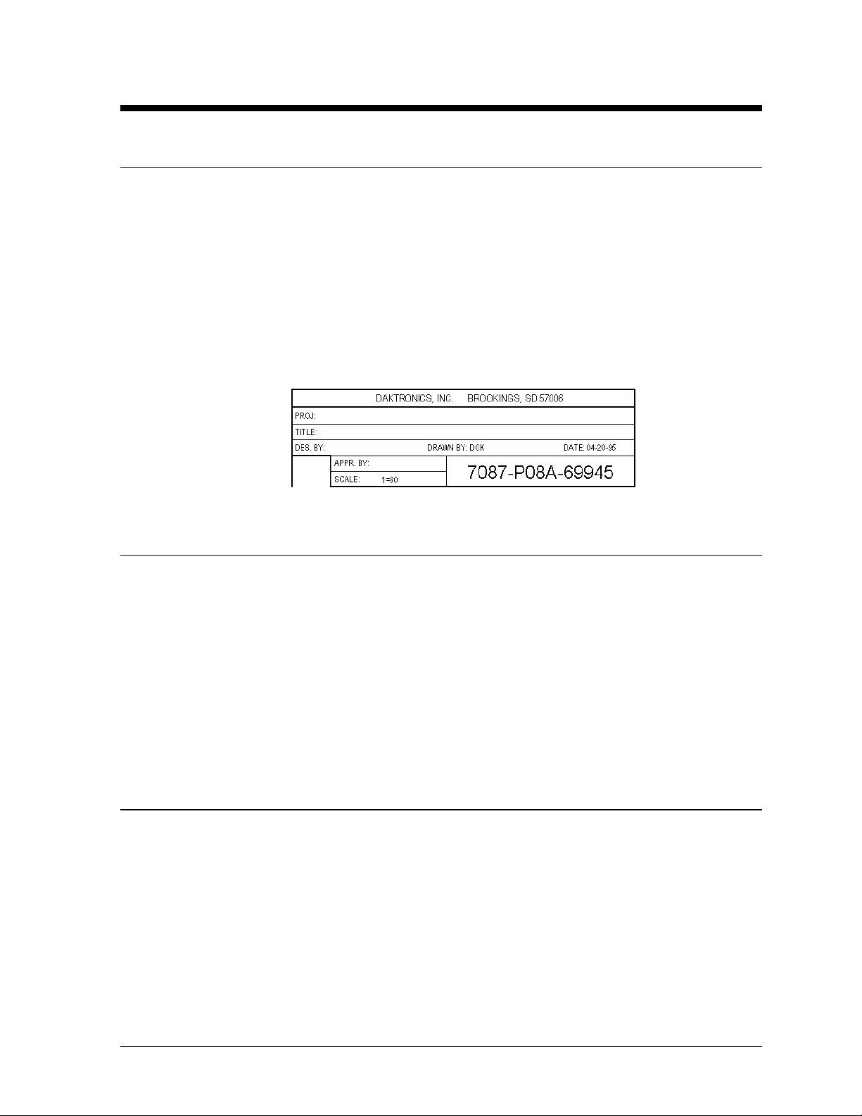
The box below is an illustration of Daktronics drawing numbering system. The drawing number
“7087-P08A-69945” is how Daktronics identifies individual drawings. This number is located
in the bottom right corner of the drawing. The manual will refer to drawings by the last five
digits and the letter preceding them. In the example, the drawing would be referred to as
Drawing A-69945. All drawings referred to as such will be inserted at the end of each section.
™
®
1500 controller. For questions regarding the safety,
, indoor multi-line
1.2 Safety Precautions
1. Read and understand these instructions before installing.
2. Be sure that the display is properly grounded.
3. Disconnect power before working on the display.
4. Do not modify the displays or attach any panels or coverings to the display without the
express written consent of Daktronics, Inc.
5. Most products are equipped with a 3-wire grounding-type plug, a plug having a third
(grounding) pin. This plug will only fit into a grounding-type power outlet. This is a
safety feature. If you are unable to insert the plug into the outlet, contact a qualified
electrician to replace your obsolete outlet. Do not defeat the purpose of the grounding-type
plug.
1.3 Network Concepts
The concept of using LED displays as a cost effective, high impact method of communication
is rapidly growing throughout many industries and businesses. The reasons for this growth are
many, but the need for additional features and complexity of multiple sign installations has
emerged, and the Daktronics display systems have been designed to meet those needs. The
common thread to most clients’ requests is a means of programming and controlling a group
of signs from a central control point. Daktronics responded by developing a powerful system
of interconnecting and controlling signs. Great care has been taken to design products that will
satisfy a wide variety of installations. Some of the design goals of these systems include the
following:
• Easy transfer of messages
• The ability to tell a sign in the network which message it should run
Introduction
1-1
Page 8

• The ability to determine the status of any sign on the network
• The ability to control multiple sign technologies on the same network
All of the programming features would seem insignificant if the installation of the systems
could not be accomplished with basic tools and without technical difficulty. Daktronics
decided to use the very popular and readily available RJ-11 connector. This connector is also
used on modern home and office telephone equipment.
All that is required for signal installation is a standard six (6) conductor modular telephone
wire. Tools required for mounting the display depend on the location and size of the display.
For some installations, it may be possible to buy pre-terminated telephone cables for use with
the displays.
There are four (4) network systems available: RS/232, RS/422, modem and TCP/IP.
1.3.1 RS/232 Network
Reference Drawing: System Riser Diagram; RS/232 ......... Drawing A-91388
RS/232 (EIA/TIA-232-E) is a standard communication interface that employs a
single-ended serial transmission scheme that uses a maximum cable length of 10
meters (30 feet). This interface was designed for computer communication at short
distances. All computers have an RS/232 communications port.
1.3.2 RS/422 Network
Reference Drawing: System Riser Diagram; RS/422 ......... Drawing A-91387
RS/422 (EIA/TIA-422-B) is a standard communication interface that utilizes a
differential balanced transmission scheme which uses a typical maximum cable length
of 1.2 km (approximately 4000 feet). The main advantage to RS/422 over RS/232 is
the longer cable length that is possible. A signal converter is needed to convert the
computer’s RS/232 to RS/422.
1.3.3 Modem Network
Reference Drawing: System Riser Diagram; Modem ......... Drawing A-91386
The modem is a standard communication interface that utilizes standard phone
transmission lines. The phone company assigns each phone line a number that the
modem uses to communicate between the controller and the display.
1.3.4 TCP/IP Network
Reference Drawing: V1500 System Riser Diagram ........... Drawing A-93904
The TCP/IP protocol is an interface allowing the Ethernet network card (installed in
the operator’s computer) to communicate with the serial server via a Local Area
Network (LAN). Information for the individual displays is distributed from the serial
server’s RS/232 output.
1-2
Introduction
Page 9

1.4 Display Overview
The Daktronics Indoor LED displays have been designed and manufactured for performance,
reliability, easy maintenance and long life. The displays consist of an array of LED pixels.
The configuration of the LED pixels is dependent on the family of LED displays. The
standard character is seven pixels high by five pixels wide.
A typical system consists of a Windows
®
based personal computer (PC) running Venus® 1500
software and one or more displays. The PC controls one or more multi-line displays. The
displays are offered as single-face displays, which are single-sided stand-alone units. They
can become double-faced by mounting them back-to-back with a second unit.
The Venus 1500 is a software package which runs under Windows 3.1x or Windows 95
operating systems on an IBM
®
-compatible computer. Refer to the Venus 1500 controller
manual, ED-12717, for installation and maintenance of the Venus 1500 editing station.
InfoNet multi-line displays are character-based indoor LED displays which are available in
monochrome red or tri-color (red, green and amber) characters. Daktronics offers multi-line
displays with a 2.1” character in four (4) different lengths. The InfoNet model numbers are
described as follows: G-X00-L-7xCCC-2.1
= InfoNet Line Display
G
= 100 = Indoor Monochrome Red
X00
= Number of Lines
L
= 7 rows high
7
CCC
= The number of columns long (120, 160, 200 and 240 are available)
= 2.1 Character Height
2.1
1.5 Part Definitions
Com Port: A Com Port is a connector on the back of the controller PC. The Com Port
is used to control the sign network through either a 9 or 25 pin serial
connector.
Display
Configuration: Display configuration refers to a display’s model number, address, etc. This
information will be automatically displayed when the display is powered up.
Display configuration is as follows:
1. Output Test (DDD’s)
2. Display Model Number (i.e. G-100-3-7x120-2.1)
3. Firmware Version
4. COM1 Configuration (typically V1500)
5. COM2 Configuration (either DataView
™
or RTD)
6. Line Interrupt Rate
7. Display Address--displayed in binary code (i.e. 001)
8. Sign Name
9. Modem present (only if modem is installed)
Flipped Cable: The flipped cable is a six (6) conductor phone cable. Pin 1 of connector A
connects to pin 6 of connector B.
LAN: Local Area Network
®
Introduction
1-3
Page 10

Loop Back Test: The loop back test is a troubleshooting test which connects the output to the
input. Contact Daktronics customer service for this test.
Module: A module is one unit of the display.
Network: A network consists of multiple signs connected to each other. Up to 240
Venus 1500 controlled displays can exist on one network.
RS/232: RS/232 is a standard PC communication type with a maximum cable length
of 25 feet (7.62 meters).
RS/422: RS/422 is a standard differential communication type with a maximum
cable length of 4000 feet (1.2 kilometers).
RX LED: A RX LED is a LED on the signal converter which indicates if the display is
sending data back to the signal converter.
Serial Server: A serial server is a device used to obtain information off of a LAN.
Sign Address: The sign address is an identification number assigned to each sign of a
network. The control software uses the address to locate and communicate
with each display. Displays which are on the same network cannot have the
same address.
Signal
Cable Tester: The signal cable tester is used to test the cable connections and data
communication
Signal
Converter: The signal converter is a Daktronics supplied unit which converts the data
from RS/232 to RS/422. The signal converter is used in RS/422 systems.
TCP/IP: The TCP/IP (Transmission Control Protocol/Internet Protocol) is a
communications protocol used for LAN’s.
TX LED: A TX LED is a LED on the serial converter which indicates the control PC
is sending data to the display.
Venus 1500: The Venus 1500 is a Daktronics designed, Windows based software used to
run the displays.
1-4
Introduction
Page 11

Section 2 : Mechanical Installation
Note: Daktronics engineering staff must approve any changes made to the display. If any
modifications are made, detailed drawings of the changes must be submitted to Daktronics for
evaluation and approval, or the warranty may be void.
2.1 Support Structure Design
Support structure design depends on mounting methods, display size and weight. The
structure design is critical and should be done only by a qualified individual. It is the
customer’s responsibility to ensure that the structure and the connectors are adequate.
Daktronics is not responsible for the installations or the structural integrity of support
structures done by others.
2.2 Display Ventilation Requirements
Fresh air inlets and exhaust vents should not be obstructed in any way. Using the Daktronics
suggested mounting methods will ensure proper ventilation. If you are using a different
mounting method, consult a Daktronics sales representative for clearance requirements
regarding your particular display. If ventilation requirements are not met, the display warranty
will be void.
2.3 Display Mounting
It is the customer’s responsibility to ensure that the installation will meet local standards. The
mounting hardware must be capable of supporting all components to be mounted. Daktronics
is not responsible for the installations or the structural integrity of support structures done by
others.
Daktronics recommends either a wall mount, a recessed mount or a hanging mount method.
Remember to have all mounted displays inspected by a qualified structural engineer.
2.3.1 Hanging Mount
Reference Drawing: Shop Drawing, G-***-2-7x***-2.1 ...... Drawing A-95540
The multi-line InfoNet has two pre-drilled holes in the top of the display for use in the
hanging mounting method. To hang a display:
1. Remove the two retaining screws from the top of the display using a
Philips screw driver.
2. Slide the provided sealing washer over the threads of each eye bolt.
3. Insert the eye bolts into the pre-drilled holes on the display (refer to
Figure 1).
4. Hand tighten the eye bolts.
Mechanical Installation
2-1
Page 12

Note: Hanging the display without using the supplied eye bolts will negate the
warranty. Attaching or hanging anything from the display will render the warranty
null and void.
Figure 1: Eye Bolt
Insertion
2.3.2 Wall Mount
Reference Drawings: Shop Dwg, G-***-2-7x***-2.1 ........... Drawing A-94764
Shop Dwg, G-***-3-7x***-2.1 ........... Drawing A-94765
Shop Dwg, G-***-4-7x***-2.1 ........... Drawing A-94766
Shop Dwg, G-***-5-7x***-2.1 ........... Drawing A-94767
Shop Dwg, G-***-6-7x***-2.1 ........... Drawing A-94768
Mtg Methods, G-***-*-7x***-2.1 ....... Drawing A-95540
The multi-line has holes on the back of the display for the attachment of the wall
mounting clips. Using the #8-32 screws provided with the display, attach the
mounting clips to the rear of the display as shown (refer to Figures 2 and 3). Use all
the supplied clips.
2-2
Figure 2: Wall Mounting Clip Attachment
1. Mount the wall bracket to the wall where the display is to be located. Refer to the
referenced shop drawings for your model of display to determine the location of
the bracket with respect to the display. Be sure the bracket is mounted to
sufficiently support the weight of the display. Have all mountings inspected by a
qualified structural engineer.
2. Set the display on the wall mounted bracket. The bracket fits onto the wall
mounting clips as shown in the reference drawings.
Figure 3: Mounting Clip Placement; Rear
View
Mechanical Installation
Page 13

2.3.3 Recessed Mount
Reference Drawings: Recessed Mounting ......................... Drawing A-95847
Refer to Section 3 for information on connecting power and signal to the sign.
1. Determine the location for the display.
2. From Drawing A-95847, determine the size of the opening required for your sign,
i.e. a G-100-3-7x160-2.1 model display would require an opening 53 ½ inches
wide by 18.05 inches tall.
3. Cut the opening for the display. For adequate ventilation of the sign, the opening
must be at least 3 ¼ inches deep.
4. Remove the face panel from the sign as described in Section 4.1. The pre-drilled
holes in the mounting channel (on the rear side of the display) will now be visible.
5. Position the display in the opening.
6. Attach the display to the wall using the pre-drilled holes (refer to Drawing A-
95847). Additional holes may be drilled to ensure adequate support.
7. Attach the face panel and power up the display.
Mechanical Installation
2-3
Page 14

Page 15

Section 3 : Electrical Installation
3.1 Signal
3.1.1 Cables
The six conductor connector used
in the network is an industry
standard, RJ-11. This connector
can be found on many
telephones.
The cable used in the network is
a standard flat six conductor
telephone cable (standard
flipped cable). Refer to Figure
4. This cable has one end that is
the mirror image of the other end
(i.e. the cable is flipped). Refer to Figure 5 for a standard flipped cable.
Notice in Figure 5 that the color code on one connector must be made the opposite on
the other connector. When installing a network, it is not easy to remember in which
direction the previous end was oriented. One simple way to avoid confusion is to
standardize the color code as one color for the connector going into the output of a
sign and the opposite color for a connector going into the input of a sign. This will
help ensure correct cabling since cables are always installed from the output jack of
one sign to the input jack of the next sign.
Figure 4: Six Conductor RJ-11 Connector and
Cable
Figure 5: Flipped Cable with RJ-11 Connectors
3.1.2 Installing an RJ-11 Connector
Installing an RJ-11 connector on the end of the six conductor cable is a simple task
when the correct tools are used. The RJ-11 crimping tool (Daktronics part number
TH-1033) performs two separate steps.
Figure 6: Wire with
Outer Jacket Stripped
Electrical Installation
First, use the crimping tool to strip the outer insulation from the inner
wires. This does not result in bare wires since only the gray outer
jacket is removed. After correct stripping, the wire will appear as
shown in Figure 6.
3-1
Page 16

The crimping tool is then used to crimp the RJ-11 connector onto the cable. The RJ11 connector is locked into a special socket in the tool. The stripped wire is inserted
into the RJ-11 connector. Finally, the tool is squeezed like a pliers to crimp the
connector onto the wire. This completes the installation of an RJ-11 connector onto
the wire.
3.2 Power
3.2.1 Power Requirements
Reference Drawings: Shop Dwg, G-***-2-7x***-2.1 .............. Drawing A-94764
Shop Dwg, G-***-3-7x***-2.1 .............. Drawing A-94765
Shop Dwg, G-***-4-7x***-2.1 .............. Drawing A-94766
Shop Dwg, G-***-5-7x***-2.1 .............. Drawing A-94767
Shop Dwg, G-***-6-7x***-2.1 .............. Drawing A-94768
Refer to the referenced drawings (found at the end of Section 2) for voltage and
current requirements. The displays are powered by a 120VAC single phase outlet.
Do not connect the display to any voltage other than that listed on the Daktronics
product label attached to the back of the display.
3.2.2 Grounding
Proper grounding is necessary for reliable equipment operation and provides some
protection to the equipment from damaging electrical disturbances. The displays are
supplied with a power cord which contains an earth ground conductor. Make sure to
plug this cord into a grounded outlet. If the proper grounding methods are not
followed, the warranty will be void.
Note: Displays must be earth grounded according to local electrical code.
3.2.3 Power Connection – Pluggable Cord Connected Displays
The multi-line displays are supplied
with a six (6) foot power cord.
The socket-outlet should be installed
near the equipment and be easily
accessible. Plug the power cord into
the socket as shown in Figure 7.
Figure 7: Power Cord Connection
3-2
Electrical Installation
Page 17

3.3 Computer to Sign
3.3.1 RS/232 System
Reference Drawing: System Riser Diagram; RS/232 ......... Drawing A-91388
Shop Dwg, G-***-2-7x***-2.1 .............. Drawing A-94764
Shop Dwg, G-***-3-7x***-2.1 .............. Drawing A-94765
Shop Dwg, G-***-4-7x***-2.1 .............. Drawing A-94766
Shop Dwg, G-***-5-7x***-2.1 .............. Drawing A-94767
Shop Dwg, G-***-6-7x***-2.1 .............. Drawing A-94768
A RS/232 system
connects the first sign
directly to the computer
with an adapter cable.
The adapter cable comes
with both a 9 pin and a
25 pin connector.
1. Plug the 9 pin or 25
pin connector
(depending on your
PC) to the PC’s
RS/232 serial COM
port.
Figure 8: Input Signal Cable Connection
2. Plug one end of the phone cable into the adapter and the opposite end into the
“RS/232 IN" jack on the rear of the display (refer to Figure 8).
The “RS/232 IN” jack’s pin out is as follows:
Pin Function
1 RTS_OUT-P
2 RESET_OUT-P
3 TX_OUT-N
4 GND-N
5 RX_IN-N
6 DCD_IN-P
3.3.2 RS/422 System
Reference Drawing: System Riser Diagram; RS/422 ......... Drawing A-91387
Shop Dwg, G-***-2-7x***-2.1 .............. Drawing A-94764
Shop Dwg, G-***-3-7x***-2.1 .............. Drawing A-94765
Shop Dwg, G-***-4-7x***-2.1 .............. Drawing A-94766
Shop Dwg, G-***-5-7x***-2.1 .............. Drawing A-94767
Shop Dwg, G-***-6-7x***-2.1 .............. Drawing A-94768
A RS/422 system requires a signal converter to connect the first sign to the computer.
1. Plug the serial cable’s 25 pin connector into the signal converter as shown in
Figure 8.
2. Plug either the 9 pin or the 25 pin connector (depending on your PC) into the
RS/232 COM port to be used.
Electrical Installation
3-3
Page 18

3. Plug the signal converter’s power cord into a 120 VAC grounded outlet.
4. Plug a flipped phone cable into the “RS/422 OUT” of the signal converter and the
opposite end into the “RS/422 IN” of the first display.
The “RS422 IN” jack’s pin out is as follows:
Pin Function
1 N.C.
2 D1OUT-P
3 D1OUT-N
4 D1IN-P
5 D1IN-N
6 N.C.
3.3.3 Modem System
Reference Drawing: System Riser Diagram; Modem ......... Drawing A-91386
A modem system uses a standard phone line to connect the computer to the sign. At
the display, simply plug in a phone cable from the J-box into the jack labeled
“PHONE IN” (the plug location is at the same point as shown in Figure 10).
At the PC, hook up the PC modem per the manufacturer’s instructions, then follow
the Venus 1500 manual (ED-12717) to determine the PC modem’s configuration.
3.3.4 TCP/IP or LAN System
Reference Drawing: V1500 System Riser Diagram ............ Drawing A-93904
A LAN system requires a computer running on a LAN.
1. Connect the serial server to the LAN. The server has an RS/232 output just as a
PC would.
2. Follow the steps for setup of a RS/232 system.
3.4 Sign to Sign Connections
Reference Drawings: RS/422 System Riser .................................. Drawing A-91387
RS/232 System Riser .................................. Drawing A-91388
The sign-to-sign connections are the same for the RS/232 system, RS/422 system, modem
system and TCP/IP system. Refer to the riser diagrams at the end of Section 2.
When wiring a sign to sign network, the cable and connectors discussed earlier in this section
are used. Pay special attention to the information regarding flipped cables to help ensure a
successful installation. The best method of wiring the signs together is to start at the first sign,
as it is designated to begin the network.
3-4
Electrical Installation
Page 19

Figure 9: Output Signal Cable Connection
1. Plug the cable into the “SIGNAL OUT”
output jack of the first sign (refer to Figure 9)
and the other end of the cable into the input
jack of the next sign.
2. Continue this procedure throughout the
network. When the wiring is complete, the
last sign will have nothing in the output jack.
Electrical Installation
3-5
Page 20

Page 21

Section 4 : Maintenance and Troubleshooting
IMPORTANT NOTES:
1. Disconnect power before any repair or maintenance work is done on the
display!
2. Any access to internal display electronics must be made by qualified
service personnel.
The multi-line InfoNet displays are FRONT ACCESS. The components within the displays are not
field repairable. In most cases, it is easiest to completely replace the failed part or return it to
Daktronics for repair.
Reference Drawings: Schematic; G-***-2-7120/7200/72400-2.1 ............... Drawing B-94385
Schematic; G-***-2-7160-2.1 .................................. Drawing B-94386
Schematic; G-***-3-7160-2.1 .................................. Drawing B-94239
Schematic; G-***-3-7120/7200/7240-2.1 ................ Drawing B-94240
Schematic; G-***-4-7160-2.1 .................................. Drawing B-94387
Schematic; G-***-4-7120/7200/7240-2.1 ................ Drawing B-94388
Schematic; G-***-5-7160-2.1 .................................. Drawing B-94390
Schematic; G-***-5-7120/7200/7240-2.1 ................ Drawing B-94392
Schematic; G-***-6-7120/7200/7240-2/1 ................ Drawing B-93896
Schematic; G-***-6-7160-2.1 .................................. Drawing B-93956
4.1 Opening the Display
Remove the socket head screws from the face panel using a 9/64" Allen wrench (refer to
Figure 10).
Figure 10: Removing the
Screws from the Face Panel
Maintenance and Troubleshooting
4-1
Page 22

Gently pull the face panel from the body of the sign.
The display opens as shown in Figure 11. The LED
module panels can now be seen.
4.2 Accessing the Interior of the Display
1. Using a #2 Philips screwdriver, turn the screws securing the LED module panel top and
bottom to the cabinet of the display one-quarter turn counter-clock-wise. The screws are
designed to remain in the LED module flanges, but release from the cabinet.
2. Gently tilt the LED module panel downward from the body of the display. It will come
forward as a complete unit. Note: Use caution when removing the LED module panel.
The ribbon cable connecting the LED’s to the inside of the display will still be connected.
3. To completely remove the LED module panel from the cabinet of the display, spread the
clasps of the 40 pin connector on the rear side of the panel. Gently pull the cable to
disconnect it (refer to Figure 12).
4. Disconnect the four-pin power connector. The power cable is released by squeezing the
tabs on each side of the connector (refer to Figure 13).
Figure 11: Display, Face Panel partially
removed.
4-2
Figure 12: LED Module Ribbon Cable
Removal
Figure 13: Disconnection of LED Module
Panel Power Cable
Maintenance and Troubleshooting
Page 23

4.3 Display Interior
Once the LED module panel is removed, the display interior will be visible. Various internal
components, including the display controller, the modem (when applicable), the light detector,
the transformer, LED modules, the power supplies and the buzzer are now accessible for
repair or replacement.
4.3.1 LED Module Replacement
If any LED modules fail, the recommended procedure is to replace the failed module
or send it to Daktronics or a certified dealer for repair. Refer to Section 4.7 for
information on packaging components for shipment.
To remove an individual LED module:
1. Disconnect the signal connection from the
failed module.
2. Gently pull the 10-pin ribbon cable from
the failed module.
3. Disconnect the power supply (refer to
Figure 14).
4. Press the tabs on each side of the four-pin
connector to release it.
Figure 14: Disconnection of Power
Supply from a LED Module
Each module is held in place by #6 screws.
Using a Philips screwdriver, remove the
module screws from the front.
Gently pull the filed module from the panel. Reverse the previous steps to attach a
new module.
4.3.2 Power Supply Replacement
Power to the LED modules is provided
by small 5V power supplies. Each power
supply can support up to four (4)
modules. They are located on the rear
side of the LED module panel.
To remove a power supply that has
failed, first remove the LED module on
the opposite side of the failed power
supply as described in Section 4.3.1.
Each power supply is secured to the
module panel with two (2) 3x10 metric
screws as shown in Figure 15. Use a #1
Figure 15: Loosening of Power Supply
Screws
Philips head screwdriver to remove the screws.
Disconnect the power cables as shown in Figure 16. The power supply is now fully
released and ready for replacement. Follow the previous steps in reverse order to
reattach the new power supply. Be sure to connect the power wires to the correct
locations. Refer to your display’s schematic for the proper wiring configuration.
Maintenance and Troubleshooting
4-3
Page 24

Figure 16: Power Supply Cable Connections
4.3.3 Display Controller
The display controller is mounted to the rear of the display cabinet in the lower left
corner (2 line displays have the controller located in the upper left side). The
controller receives information from the computer, interprets it and activates the
appropriate LED’s on the display.
Figure 17: Display Controller; Front View
The
display controller also has a set of eight (8) switches (located on the left side of the
controller) by which an address can be set using standard binary code (refer to
Section 4.4). Refer to Section 1.5 for information on sign addressing.
To replace a failed controller:
1. Disconnect all attached cables. Take note of their orientation.
2. Remove all #6 connecting screws. If the address switches are used, take note of
the switch configuration and set the same address on the new controller.
3. Attach the new controller using #6-32 screws.
4.3.4 Modem
If a modem was ordered with the display, it will be mounted inside the display
cabinet, near the controller. The modem is used in lieu of a direct communication line
with the computer.
The modem is held in place with the use of plastic rails known as a “snap track.” To
replace a failed modem, disconnect all attached cables and carefully “snap” it out of
the rails. Insert the new modem by first laying one end into the rails of the “snap
track,” then pivot it up and snap into place.
4-4
Maintenance and Troubleshooting
Page 25

4.3.5 Light Detector
A light detector is located in the bottom of the left flange. The light detector is used
to measure light levels outside the display and, when enabled through the Venus 1500
software, adjusts the brightness level of the LED’s appropriately.
The light detector is mounted on a support flange. To replace the light detector, first
remove the #6 screws attaching the support flange to the inside of the display.
Disconnect the light detector’s wire to the display controller. The light detector is
attached to the support flange with #4 screws, standoffs and nuts. Remove the failed
light detector from the support flange. Reverse these steps to attach the new light
detector.
4.3.6 Fuse
The MDL-7 fuse is located in the left end
of the cabinet, near the display controller
(refer to Figure 18).
To replace the fuse, push and turn the fuse
cap, insert the new fuse into the cap and
reattach.
4.4 Controller Address and Test Mode
The controller has a set of “DIP” switches on the side of the controller as
shown in Figure 19. These DIP switches set the hardware address. When
replacing a controller board, be sure to set the DIP switches in the same
address configuration as the defective controller.
Note: A test mode can be activated by setting the DIP switches to address
0 (flip all the switches toward the numbers on the circuit board). The
display’s power must be downed, then reconnected to run the test mode.
Figure 18: Fuse
Figure 19: DIP
Switches
Address Switch 1 Switch 2 Switch 3 Switch 4 Switch 5 Switch 6 Switch 7 Switch
1 ON OFF OFF OFF OFF OFF OFF OFF
2 OFF ON OFF OFF OFF OFF OFF OFF
3 ON ON OFF OFF OFF OFF OFF OFF
4 OFF OFF ON OFF OFF OFF OFF OFF
5 ON OFF ON OFF OFF OFF OFF OFF
6 OFF ON ON OFF OFF OFF OFF OFF
7 ON ON ON OFF OFF OFF OFF OFF
8 OFF OFF OFF ON OFF OFF OFF OFF
9 ON OFF OFF ON OFF OFF OFF OFF
10 OFF ON OFF ON OFF OFF OFF OFF
Maintenance and Troubleshooting
8
4-5
Page 26

11 ON ON OFF ON OFF OFF OFF OFF
12 ON ON ON ON ON ON ON ON
4.5 Troubleshooting
This section contains some symptoms that may be encountered with the LED displays. Possible
remedies are provided. This list does not include every possible problem, but does represent
some of the more common situations that may occur.
Symptoms/Conditions Possible Causes/Remedy
Cannot communicate with the display
Display will not run.
Entire display is garbled or a section
of the display is bad.
Section of the network of displays is
not working.
Note: The display configuration will be shown on power up and will contain the following
information:
1. Output Test (DDD’s)
2. Display Model Number (i.e. G-100-3-7x120-2.1)
3. Firmware Version
4. COM1 Configuration (typically V1500)
5. COM2 Configuration (either DataView or RTD)
6. Line Interrupt Rate
7. Display Address--displayed in binary code (i.e. 001)
8. Sign Name
9. Modem Present (only if a modem is connected)
4.6 Replacement Parts
Part Description Daktronics Part No.
Display Controller (RS232) 0A-1156-0013
Display Controller (RS422) 0A-1156-0014
Display Internal Modem 0P-1146-0003
Module; Mono. Red 0P-1156-0002
Module; Tri-Color 0P-1156-0001
Light Detector 0P-1151-0002
4-6
• Check flipped phone cable connections.
• Check display configuration.
• Check Venus 1500 configuration
• Check signal converter power and TX LED’s.
• Contact Daktronics customer service.
• Check power cord.
• Check the fuse.
• Power down then power up the display
(reset)
• Contact Daktronics customer service
• Power down, then power up display (reset)
• Contact Daktronics customer service.
• Bad input on first bad display.
• Bad output on last good display.
• Switch the suspected bad display with a
known good display.
• Contact Daktronics customer service.
Maintenance and Troubleshooting
Page 27

Power Supplies A-1499
Buzzer DS-1357
120V Transformer T-1072
Fuse, MDL-7 F-1031
Power Cord W-1181
Module Ribbon Cable W-1362
Controller Ribbon Cable Set
2 Line Display
3 Line Display
4 Line Display
5 Line Display
6 Line Display
“Door Split” Ribbon Cable Set
2 Line Display
3 Line Display
4 Line Display
5 Line Display
6 Line Display
Signal Converter 0A-1127-0237
Signal Converter Serial Cable W-1363
Serial Server A-1557
LAN Patch Cable W-1383
PC DB9-RJ11 0A-1115-0042
PC DB25-RJ11 0A-1115-0044
25’ RJ-11 Cable W-1265
100’ RJ-11 Cable 0A-1146-0002
500’ RJ-11 Cable 0A-1146-0003
1000’ RJ-11 Cable 0A-1146-0004
Six Conductor Signal Wire W-1368
RJ-11 Connector P-1071
Crimp Tool TH-1033
Cable Tester 0A-1146-0005
Venus 1500 Manual ED-12717
Temperature Sensor 0P-1151-0003
Temperature Sensor Cable W-1234
4.7 Unit Exchange/Replacement Procedure
Daktronics unique exchange program offers our clients the quickest, most economical way of
receiving product repairs. If a component fails, Daktronics will send the customer a
replacement. The customer, in turn, sends the failed component to Daktronics. This not only
saves money but decreases the time the display is inoperable. Daktronics offers repair and
return on a timely basis; in urgent situations, every attempt is made to ship by the fastest
transit method available.
1. Packaging for Return: Package and pad the item well to prevent damage during
shipment. Electronic components, such as printed circuit boards, should either be
installed in an enclosure or placed in an anti-static bag before boxing.
Please enclose your name and address along with a list of all the symptoms. Please be as
specific as possible.
0A-1156-0069
0A-1156-0070
0A-1156-0071
0A-1156-0072
0A-1156-0073
0A-1156-0074
0A-1156-0075
0A-1156-0076
0A-1156-0077
0A-1156-0078
Maintenance and Troubleshooting
4-7
Page 28

2. Driver Packaging Instructions: Drivers should be placed in a static-free enclosure
for return shipping. An anti-static convoluted foam packing is available from
Daktronics (part number PK-1135). The shipping box (Daktronics part number PK-
1006) should be used along with the foam.
3. Where to Send: Contact your local representative prior to shipment to acquire a
Return Material Authorization Number (RMA#). This will speed up the repair of
your unit.
When returning defective items under the exchange program, please use the UPS Blue
Return Tags found in the package containing the exchange unit sent from Daktronics.
This will speed up the transaction and help avoid confusion when the part is returned
to Daktronics. The defective item must be returned within 15 days of receiving a
replacement part. Using the UPS Blue Return Tag immediately will eliminate the
possibility of late charges being assessed against your account.
Mail: Daktronics, Inc., Customer Service
PO Box 5128
331 32
nd
Avenue
Brookings, SD 57006
Phone: Toll Free: 1-800-843-9879
or 1-605-697-4400
Customer Service Fax: 1-605-697-4444
E-Mail: helpdesk@daktronics.com
4.8 Daktronics Warranty and Limitation of Liability
Daktronics Warranty and Limitation of Liability information is located in Append ix B. The Warranty is
independent of Extended Service agreement and is the authority in matters of service, repair, and
display operation.
4-8
Maintenance and Troubleshooting
Page 29

Appendix A: Optional Temperature Sensor
The multi-line InfoNet displays may be ordered with an
optional temperature sensor (0A-1151-0002). Follow the
supplied mounting instructions to attach the temperature
sensor and housing.
The temperature sensor cable connects to the back of the
display using the removable green jack (refer to Figure
20).
Figure 20: Temperature Sensor Cable
Connection
The pin orientation of the jack is shown in Figure 21.
Connect the temperature sensor cable to the jack as follows:
Figure 21: Pin Orientation
Display Cable Wires Temperature Sensor
Pin 1 Green P
Pin 2 White N
Pin 3 Red +V
Pin 4 Black GND
Pin 5 Bare N/A
Appendix A
A-1
Page 30

Page 31

Appendix B: Daktronics Warranty and
Limitation of Liability (SL-02374)
Daktronics Warranty and Limitation of Liability (SL-02374)
B-1
 Loading...