

Page 1
G-1000 Series InfoNet
™
Outdoor LED Displays
Installation/Maintenance
Manual
ED-8157
®
Venus is a registered trademark of Daktronics, Inc.
InfoNet and DataView are trademarks of Daktronics, Inc.
™ ™
Windows is a trademark of Microsoft Corp.
™
ED#8157
Product#1137
Rev. 5 - 3 April 2001
Copyright © 1996 -- 2001 Daktronics, Inc.
All rights reserved. While every precaution
has been taken in the preparation of this
manual, the publisher assumes no
responsibility for errors or omissions. No part
of this book covered by the copyrights hereon
may be reproduced or copied in any form or
by any means - graphic, electronic, or
mechanical, including photocopying, taping,
or information storage and retrieval systems without written permission of the publisher.
DAKTRONICS, INC.
P.O. Box 5128 331 32nd Ave. Brookings, SD 57006
Phone (605) 697-4034 or (877)605-1113 Fax 697-4444
www.daktronics.com e-mail helpdesk@daktronics.com
Page 2

Page 3

Table of Contents
1. Introduction ............................................................1-1
1.1 How To Use This Manual .................................................1-1
1.2 Display Overview ........................................................1-1
1.3 Definitions .............................................................1-2
2. Mechanical Installation ...................................................2-1
2.1 Mounting Kit ...........................................................2-1
2.2 Cabinet Display Mounting .................................................2-1
2.2.1 Wall Mount ......................................................2-1
2.2.2 Pole Mount ......................................................2-2
3. Electrical Installation .....................................................3-1
3.1 Conduit ................................................................3-1
3.2 Grounding ..............................................................3-1
3.2.1 New Power Installation .............................................3-2
3.2.2 Existing Power Installation With No Earth Ground Conductor ..............3-2
3.3 Control Cable Requirements ................................................3-3
3.3.1 RS/232 .........................................................3-3
3.3.2 RS/422 .........................................................3-3
3.3.3 Modem .........................................................3-3
3.4 Signal Termination From Computer To Display ................................3-3
3.4.1 RS/232 .........................................................3-3
3.4.2 RS/422 .........................................................3-4
3.4.3 Modem .........................................................3-4
3.5 Signal Termination Between Two (or more) Displays ............................3-5
3.6 First Time Turn On .......................................................3-5
4. Maintenance & Troubleshooting ...........................................4-1
4.1 Weather Stripping ........................................................4-1
4.2 Module Numbering Convention .............................................4-1
4.3 Display Access/Module Removal ............................................4-2
4.4 LED Driver Replacement ..................................................4-3
4.5 Power Supply ...........................................................4-3
4.6 Controller Board .........................................................4-4
4.6.1 Accessing and Replacing the Controller Board ..........................4-4
4.6.2 LED’s and Jumpers ................................................4-5
4.6.3 Controller Address and Test Mode ....................................4-5
4.7 Light Detector ...........................................................4-6
4.8 Transformer ............................................................4-6
4.9 Modem ................................................................4-6
4.9.1 Accessing and Replacing the Modem ..................................4-6
4.9.2 LEDs and Jumpers ................................................4-7
4.10 Structural Inspection ......................................................4-7
Table of Contents
i
Page 4

4.11 Troubleshooting .........................................................4-7
4.12 Boot Up Initialization Information ...........................................4-8
4.13 Replacement Parts .......................................................4-8
4.14 Unit Exchange/Replacement Procedure .......................................4-9
Appendix A: Optional Temp Sensor ........................................... A-1
Appendix B: G-1000 Design Prior To November 1, 1996 ........................... B-1
Appendix C: RS/422 System (Old Signal Converter) .............................. C-1
ii
Table of Contents
Page 5

List of Figures
Figure 1. New Power Installation .......................................................3-2
Figure 2. Existing Power Installation .....................................................3-2
Figure 3. Module Identification Numbering Convention .....................................4-1
Figure 4. Removing the End Cap ........................................................4-2
Figure 5. Sliding Out the Face Panel .....................................................4-2
Figure 6. Removing the Mounting Nuts ..................................................4-2
Figure 7. Opening the Display ..........................................................4-2
Figure 8. Rear View; Module ..........................................................4-3
Figure 9. Removing the Signal Connections ...............................................4-3
Figure 10. Module Power Supply .......................................................4-3
Figure 11. Controller Board ............................................................4-4
Figure 12. Location of DIP Switches .....................................................4-5
Figure 13. Modem ...................................................................4-6
List of Figures
iii
Page 6

Page 7
Section 1: Introduction
1.1 How To Use This Manual
This manual is designed to explain installation of outdoor InfoNet Displays. Details for display
maintenance are also given. For questions regarding the safety, installation, operation or service of
this system, please refer to the telephone numbers listed on the cover page of this manual.
Important Safeguards:
1. Read and understand these instructions before installing.
2. Do not drop the control equipment or allow it to get wet.
3. Disconnect power when servicing the display.
4. Do not modify the display structure or attach any panels or coverings to the display
without the express written consent of Daktronics, Inc.
5. Care must be taken when handling the display’s face panel to prevent any injuries
or damage, especially in windy conditions.
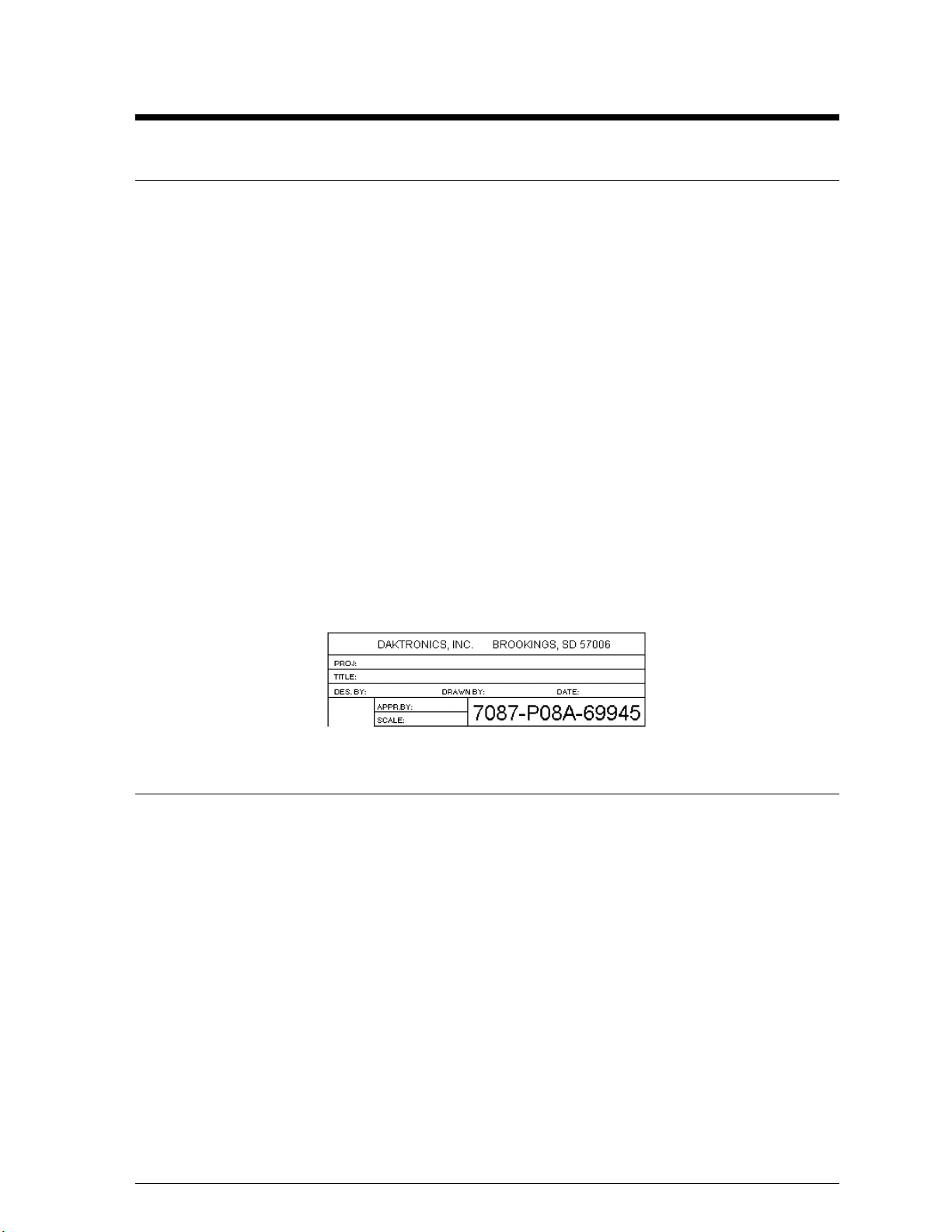
The box below is an illustration of Daktronics drawing numbering system. The drawing number
“7087-P08A-69945” is how Daktronics identifies individual drawings. This number is located in
the bottom right corner of the drawing. The manual will refer to drawings by calling out the last
five digits and the letter preceding them. In the example, the drawing would be referred to as
Drawing A-69945. All drawings referred to as such will be inserted at the end of the section they
are first referenced in.
™
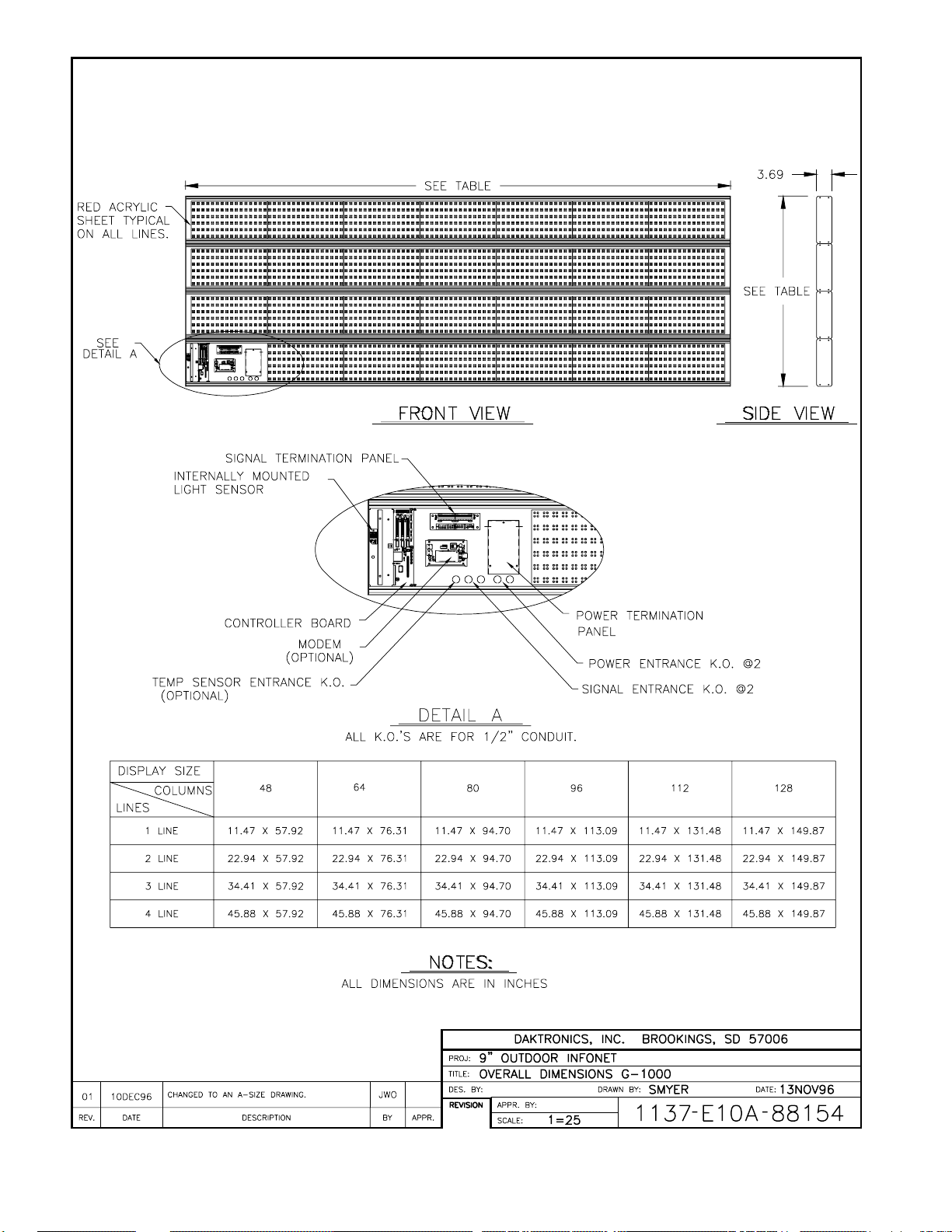
1.2 Display Overview
Reference Drawings: Overall Dimensions; G-1000 ................ Drawing A-88154
Note: This manual has been revised to reflect design changes to the G-1000 product family.
Displays manufactured before NOVEMBER 1, 1996, please refer to Appendix B.
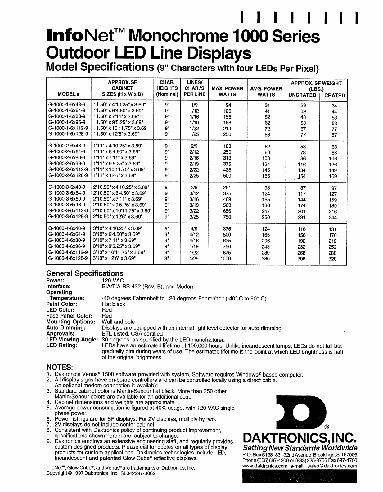
The outdoor InfoNet display uses LEDs for long life and reliable operation. Four (4) LEDs are
grouped together to form a single pixel and each line uses six (6) pixels high to create a character.
The InfoNet series are line displays and are programmed using the Daktronics Venus 1500
software (refer to the Venus 1500 manual for operation instructions).
Daktronics has standardized a complete line of outdoor InfoNet displays. These displays are
standard, but have several options for mounting kits and signal communications.
Introduction 1-1
®
Page 8

1.3 Definitions
Column: A vertical group of pixels.
Controller Board: Controls the data for the entire display. It is located behind the left module
in the bottom line.
Driver: Located on the back of the display board.
Display Board: A 6 row x 16 column array of pixels.
End Cap: The side panel that keeps the face panel in place. It must be removed for
display access.
Face Panel: The plexi-glass on each line that goes in front of the modules.
LED: An LED is an electrical component and is short for Light Emitting Diode. There
are 384 LEDs per module.
Line: A horizontal group of modules.
Module: Contains the LEDs, display board and the driver.
Network: A network consists of multiple signs connected to each other. Up to 240 Venus
1500 controlled displays can exist on one network.
Pixel: A group of four (4) LEDs.
RS/232: RS/232 is a standard PC communication type with a maximum cable length of
25 feet (7.6 meters).
RS/422: RS/422 is a standard differential communication type with a maximum cable
length of 4000 feet (1.2 kilometers).
Row: A horizontal group of pixels.
Sign Address: The sign address is an identification number assigned to each sign of a network.
The control software uses the address to locate and communicate with each
display. Displays which are on the same network cannot have the same
address.
Venus 1500: The Venus 1500 is a Daktronics designed, Windows based software used to
®
edit the displays.
Introduction1-2
Page 9
Page 10

Page 11
Page 12

Page 13

Section 2: Mechanical Installation
The Daktronics Product Manager’s engineering staff must approve any changes that
may affect the weather tightness of the display. This to include, but not limited to, the
border shrouding and back sheets. If ANY modifications are made to the weather
tightness of the display, detailed drawings of the changes MUST be submitted to our
engineering staff for evaluation and approval or the warranty will be null and void.
Daktronics is not responsible for the integrity of the mounting structure or any
mounting hardware not provided by Daktronics. It is the customers responsibility to
ensure that the structure and any additional hardware have been approved by a
qualified structural engineer.
2.1 Mounting Kit
An optional mounting kit is available when ordering a display. The mounting kit includes the
hardware to either mount the display on a pole or to a wall. Please specify the desired mounting
method when ordering a mounting kit. When using a Daktronics mounting kit, refer to the
instructions in Section 2.2.
2.2 Cabinet Display Mounting
L Note: There are end caps located at either end of the display for maintenance access. Care
must be taken when mounting the display not to obstruct the end caps. The following two example
mounting methods, wall mount and pole mount, take this into consideration.
2.2.1 Wall Mount
Reference Drawings: Wall Mount ...................... Drawing A-79703
L Note: Because each site differs, the Daktronics wall mount kit is not a complete
installation kit. It is the customer’s responsibility to determine the proper wall mounting
method and location.
Refer to Drawing A-79703 for a suggested mounting method. The number of wall
brackets needed and the wall structure must be reviewed by a qualified structural engineer
and meet all local codes.
One (1) Daktronics provided mounting kit includes:
C angle bracket (qty. 1)
C d" lock washers (qty. 2)
C d" nuts (qty. 2)
Note: A multi-line display requires two mounting kits.
Mechanical Installation 2-1
Page 14

1. Attach the angle bracket to the d" bolts on the back of the display using d"
washers and nuts.
2. Mount the customer specified mounting brackets to the wall.
3. Position the display and its mounting angle brackets over the wall mount brackets
as shown in Drawing A-79703.
4. Attach the two support brackets together using customer supplied hardware.
5. Be sure that all mounting hardware is tight before releasing the display.
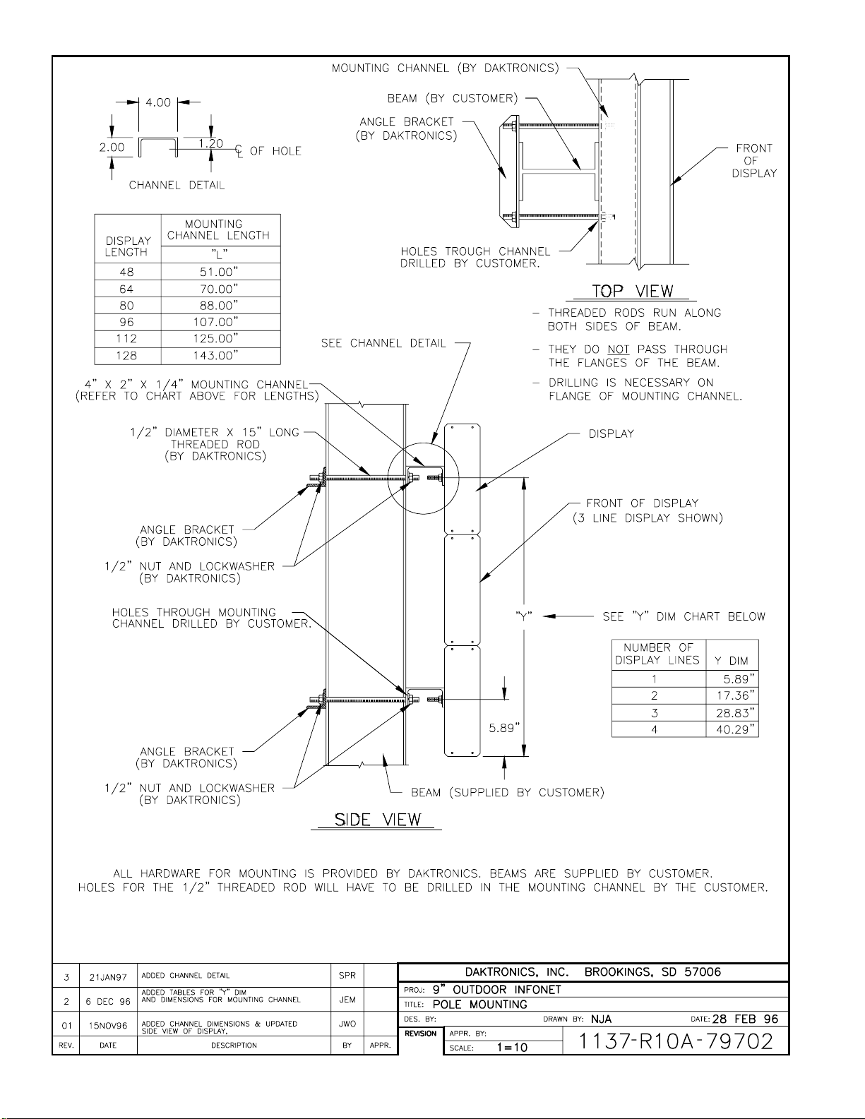
2.2.2 Pole Mount
Reference Drawings: Pole Mount .......................Drawing A-79702
Refer to Drawing A-79702 for a suggested mounting method. The location of the poles
needs to be determined by the customer. The number of poles needed and the pole
structure and footings must be reviewed by a qualified structural engineer and meet all
local codes.
One (1) Daktronics provided mounting kit includes:
C channel (qty. 1)
C angle (qty. 1)
C d" nuts (qty. 2)
C d" lock washers (qty. 2)
C ½" threaded rods (qty. 4)
C ½" nuts (qty. 8)
C ½" washer (qty. 8)
L Note: A multi-line display requires two mounting kits.
1. Mount the channel to the d" bolts on the back of the display using d" washers
and nuts.
2. Drill a 9/16" hole in the opposite flange of the mounting channel for each of the ½"
threaded rods. O Note: One threaded rod will go to each side of the
mounting pole. The threaded rods should NOT pierce any of the pole’s
flanges (refer to Drawing A-79702).
3. Position the display on the pole.
4. Use ½" nuts and washers to attach the threaded rods to the channel.
5. Position the angle(s) on the opposite side of the pole from the display and slide the
angle(s) onto the threaded rods. Secure the angle(s) with ½" nuts and washers.
6. Be sure that all mounting hardware is tight before releasing the display.
Mechanical
Installation2-2
Page 15
Page 16

Page 17

Section 3: Electrical Installation
3.1 Conduit
Reference Drawings: System Riser Diagram (422) ............... Drawing A-88425
System Riser Diagram (Modem) ............. Drawing A-88426
Power/Signal Termination Panel ............. Drawing A-88427
Overall Dimensions; G-1000 ................ Drawing A-88154
Daktronics does not include the conduit. Knockouts will be provided. Separate conduit must
be used to route:
C power
C signal IN wires
C signal OUT wires (if signal is required for another display).
The conduit holes are located at the bottom right (rear view) of the back of the display.
To access the knockouts, remove the right end cap (front view) on the bottom line and slide the
face panel out until the left module is cleared. Refer to Drawing A-88154 (Section 1) and Section
4.3 to remove the module.
Punch or drill out the desired knockouts. Note: Be careful that none of the components are damaged.
Attach the conduit and route the power and signal cables. Refer to Drawing A-88427 for the signal
and power termination panel.
For displays with more than one face, signal and temperature sensor wiring between the displays can
be routed through the same conduit.
3.2 Grounding
The display must be connected to earth-ground. Proper grounding is necessary for reliable
equipment operation. It also serves to provide protection to the equipment against damaging
electrical disturbances and lightning. If the following grounding methods are not adhered to,
the warranty will be void.
˜ Displays MUST be grounded according to the provisions outlined in Article 250 of the
National Electrical Code.˜
The support structure for the display cannot be used as grounding. The support is generally
embedded in concrete, and if in earth, the support is either primed or it corrodes, making it a poor
ground. Use one ground rod at each support column.
The National Electrical Code requires the use of a lockable power disconnect near the display.
Provide a lockable disconnect switch (knife switch) at the display location so that all power lines
can be completely disconnected. Use a multi-conductor disconnect so that all the hot and the
neutral lines can be disconnected. This is important in protecting the display against lightning.
There are two considerations for power installation, New Power and Existing Power Installation.
These two power installations differ slightly, as described in the following paragraphs.
Electrical
Installation 3-1
Page 18

3.2.1 New Power Installation
The power cable must contain a separate earth-ground conductor. When a separate
ground conductor is used, do not connect neutral to ground at either the disconnect or the
display. To do so violates electrical codes and voids the warranty (refer to Figure 1).
Figure 1: New Power Installation
3.2.2 Existing Power Installation With No Earth Ground Conductor
When a separate ground conductor is not available, connect the neutral to the earth-ground
at the disconnect, never at the display (refer to Figure 2).
Figure 2: Existing Power Installation
Electrical
Installation3-2
Page 19

3.3 Control Cable Requirements
3.3.1 RS/232
This cable is a 2-conductor shielded cable used to transmit a RS/232 signal (Daktronics
part number W-1117). This shielded cable should not be subjected to mechanical flexing
after installation. This cable is not for direct burial and should be routed in a dedicated,
grounded metallic conduit at the base of the display structure. This cable has a maximum
length of 25 feet.
3.3.2 RS/422
This cable is a 6-conductor unshielded cable used to transmit a RS/422 signal (Daktronics
part number W-1210). This unshielded cable consists of paired wires. They should not be
subjected to mechanical flexing after installation. This cable is not for direct burial and
should have one of the following routings:
1. In dedicated metallic conduit
2. In plastic conduit away from interference signals
3. Inside buildings - if cable is not in conduit, keep away from interference signals.
L With interference signals, such as power conductors, intercom, etc., a two-
foot separation is typically required.
3.3.3 Modem
The modem option will use standard telephone cable routed through conduit. The local
telephone company will need to assist in this installation.
Ask the telephone company which colors are used by the TIP, and the RING for signal
hook up. U Note: The telephone lines must be dedicated lines and not run through a
switch board/communications system.
3.4 Signal Termination From Computer To Display
3.4.1 RS/232
Reference Drawings: Signal/Power Termination Panel ..... Drawing A-88427
System Riser Diagram (232) ........ Drawing A-96058
One end of the signal cable should be terminated to the 10 position terminal block in the display
labeled “DATA IN” (TB42). Drawing A-88427 is an example of the termination panels. The
other end is terminated at the J-box at the display structure. The laptop PC connects to the
J-box through the serial cable (refer to Drawing A-96058).
Electrical
Installation 3-3
Page 20

J-Box Field Cabling Terminal Block (Data In)
Pin 1 (N.C.)
Pin 2 (N.C.)
Pin 2 (RX-P) Clear Pin 3 (TX-P)
Pin 3 (GND) Shield Pin 4 (GND)
Pin 1 (TX-P) Black Pin 5 (RX-P)
Pin 6 (N.C.)
3.4.2 RS/422
Reference Drawings: Signal/Power Termination Panel ......Drawing A-88427
System Riser Diagram (422) .........Drawing A-92681
One end of the signal cable should be terminated to the 10 position terminal block in the display
labeled “DATA IN” (TB42). Drawing A-88427 is an example of the termination panels. The
other end is terminated at the signal converter (Daktronics part number 0A-1127-0237) in the
control room.
Signal Converter (J4/J5) Field Cabling Terminal Block (Data In)
Pin 1 (GND) Red Pin 1 (GND)
Pin 2 (RX-P) Black Pin 2 (TX-P)
Pin 3 (RX-N) Brown Pin 3 (TX-N)
Pin 4 (TX-P) White Pin 4 (RX-P)
Pin 5 (TX-N) Blue Pin 5 (RX-N)
Pin 6 (GND) Green Pin 6 (GND)
Shield (Bare) N.C.
3.4.3 Modem
Reference Drawings: System Riser Diagram (Modem) .....Drawing A-88426
Terminate the signal telephone wires in TB42 as follows:
Signal/Power Termination Panel ..... Drawing A-88427
Telephone Wires Terminal Block
N.C. Pin 1
N.C. Pin 2
TIP-P Pin 3
Ring-P Pin 4
N.C. Pin 5
N.C. Pin 6
Electrical
Installation3-4
Page 21

3.5 Signal Termination Between Two (or more) Displays
Reference Drawings: System Riser Diagram (422) ................ Drawing A-88425
System Riser Diagram (Modem) ............. Drawing A-88426
Signal/Power Termination Panel ............. Drawing A-88427
This is the most common method of terminating signal between two or more signs. A 6-conductor
cable is used and one end terminates at the “DATA OUT” 10 position terminal block (TB43) on the
first display. The other end terminates at the “DATA IN” 10 position terminal block (TB42) in the
second display.
Sign A Sign B
Data Out (TB43) Field Cabling Data In (TB42)
Pin 1 (GND) Green Pin 6 (GND)
Pin 2 (Data TX-N) Blue Pin 5 (Data RX-N)
Pin 3 (Data TX-P) White Pin 4 (Data RX-P)
Pin 4 (Data RX-N) Brown Pin 3 (Data TX-N)
Pin 5 (Data RX-P) Black Pin 2 (Data TX-P)
Pin 6 (GND) Red Pin 1 (GND)
Shield (Bare) N.C.
3.6 First Time Turn On
When first powered up, the display will run through an initialization in which it will display the
following:
1. Output Test (DDD’s)
2. Display Model Number (i.e. G-1000-3-6x96)
3. Firmware Version
4. COM1 Configuration (Typically V1500)
5. COM2 Configuration (Either DataView or RTD)
™
6. Power Line Frequency (i.e. 60 Hz)
7. Display Address
8. Sign Name
9. Modem (if present)
Electrical
Installation 3-5
Page 22

Page 23

Page 24

Page 25

Page 26

Page 27

Page 28

Section 4: Maintenance & Troubleshooting
IMPORTANT NOTES:
1. Disconnect power before any repair or maintenance work is done
on the display!
2. Any access to internal display electronics must be made by
qualified service personnel.
3. The Daktronics product manager’s engineering staff must approve
any changes that may affect the weather tightness of the display.
This includes, but is not limited to, the border shrouding and back
sheets. If ANY modifications are made to the weather tightness of
the display, detailed drawings of the changes MUST BE submitted
to our engineering staff for evaluation and approval or the
warranty will be null and void.
4. Care must be taken when handling the display’s face panel to
prevent any injuries or damage, especially in windy conditions.
4.1 Weather Stripping
To ensure that the display is waterproof, weather stripping has been provided around the entire
display and around the individual lines. It is important that the weather stripping is installed
properly at all times or water may leak into the display and damage components.
4.2 Module Numbering Convention
Figure 3 shows the module numbering convention. A module is six pixels high by sixteen pixels wide,
with the driver board attached. A, B and C designate modules for each face on a multiple face display.
A101 A102 A103 A104 A105 A106 Line 1
A201 A202 A203 A204 A205 A206 Line 2
A301 A302 A303 A304 A305 A306 Line 3
1. Labeling reference begins with the upper left module and increments to the right and down
from that point, independent of the display size.
2. Modules are designated by the prefix “A”. A101 represents the upper left module.
3. The hundreds digit indicates the display line number. A101 through A106 make up the first
display line, A201 through A206 make up the second display line and so forth.
Figure 3: Module Identification Numbering Convention
Maintenance &
Troubleshooting 4-1
Page 29

4.3 Display Access/Module Removal
To access the display, some of the modules will need to be removed. Refer to the following
instructions to remove a module:
1. Remove the screws from the end cap for
the line on the side farthest from the
module (refer to Figure 4) to be
removed. Detach the end cap.
2. Slide the face panel out until it passes the
desired module (refer to Figure 5).
Note: Care must be taken when handling
these long face panels to prevent damage
and injuries. Take extra precautions
Figure 4: Removing the end cap
during windy conditions.
3. Remove the four mounting nuts. There
is one located in each corner of the
module (refer to Figure 6).
4. Carefully pull the module forward so that the connections
can be unplugged (see Figure 7).
To install or replace the modules, follow the above steps in
reverse order.
Figure 5: Sliding out the face panel.
Figure 6: Removing the mounting nuts.
Figure 7: Opening the display
Maintenance &
Troubleshooting4-2
Page 30

4.4 LED Driver Replacement
The LED driver is located on the rear side of the module (refer to Figure 8).
1. Remove all power and signal connections from the board. The connectors can be released
by squeezing together the locking tabs, then gently pulling the connector free (refer to
Figure 9).
2. Remove the four corner #6 screws.
3. Take note of the driver’s orientation.
4. Carefully remove the driver from the display board. Use an even force to prevent any
damage due to bending of the connector pins on the display board.
Reverse the above steps to replace the driver.
Figure 8: Rear View; Display Module
4.5 Power Supply
Figure 10: Module Power Supply
Figure 9: Removing the signal connections
The power supply is mounted on the back of every other
module. The first power supply is located behind module
A*02 (* is the number of the line. Refer to Section 4.2).
This unit supplies power to modules A*01 and A*02. The
remaining power supplies are located behind A*03, A*05,
A*07 and A*09. The power supplies connect to the module
they are located behind and the one to the right of it (as seen
from the front view). This pattern is consistent for each line.
Refer to Section 4.3 for information on removing a module.
Once the module has been removed from the display:
1. Remove the ground wire from the ground nut.
2. Unplug the two power wires.
3. Place the module face down on a soft, flat
surface.
4. Remove the power module by removing the single
screw on the bottom L-bracket.
5. Pull and slide out the power module.
Follow the above steps in reverse order to install a new power supply.
Maintenance &
Troubleshooting 4-3
Page 31

4.6 Controller Board
4.6.1 Accessing and Replacing the Controller Board
Reference Drawings: System Riser Diagram (422) .........Drawing A-88425
Overall Dimensions; G-1000 .........Drawing A-88154
The controller board is located behind the module on the far left side of the bottom row (front
view). Refer to Drawing A-88425 (Section 3).
1. To access the board, first remove the module in front of the controller board (refer
to Section 4.3).
2. Remove all power and signal connections. “Locked” connectors can be released by
squeezing together the tabs, then carefully pulling them from the jack.
3. Remove the ground mounting screw on the right side.
4. Slide the board out the end of the display.
Follow the above steps in reverse order to install a new controller board.
Figure 11: Controller Board
Maintenance &
Troubleshooting4-4
Page 32

4.6.2 LED’s and Jumpers
The controller board contains three (3) DIM, one (1) Power, one (1) RUN, and one (1)
Receive Data LED’s. They are located as shown in Figure 11.
The controller’s communication module contains a jumper for a modem system. The
jumper must jump both pins for a modem system. For all other applications, the jumper
must be removed.
4.6.3 Controller Address and Test Mode
Before a display can be run in a sign network, it must have an
“address.” The display address can be set by the use of “DIP”
switches located on a PC board known as the MDC. The MDC
is the circuit card mounted in the lower right corner of the
controller board (as seen in Figure 11).
Locate the DIP switches on the MDC. They should be on the
bottom end of the card (if it is oriented as shown in Figure 11).
Refer to Figure 12 for a picture of the DIP switches.
When replacing a controller board, be sure to set the DIP
switches in the same address configuration as the defective
controller.
Note: A test mode can be activated by setting the DIP
switches to address 0 (flip all the switches toward the numbers
on the circuit board). The display’s power must be downed,
then reconnected to run the test mode.
Figure 12: Location of DIP Switches
Address Switch Switch Switch Switch Switch Switch Switch Switch
1 2 3 4 5 6 7 8
1 ON OFF OFF OFF OFF OFF OFF OFF
2 OFF ON OFF OFF OFF OFF OFF OFF
3 ON ON OFF OFF OFF OFF OFF OFF
4 OFF OFF ON OFF OFF OFF OFF OFF
5 ON OFF ON OFF OFF OFF OFF OFF
6 OFF ON ON OFF OFF OFF OFF OFF
7 ON ON ON OFF OFF OFF OFF OFF
8 OFF OFF OFF ON OFF OFF OFF OFF
9 ON OFF OFF ON OFF OFF OFF OFF
10 OFF ON OFF ON OFF OFF OFF OFF
11 ON ON OFF ON OFF OFF OFF OFF
... ... ... ... ... ... ... ... ...
127 ON ON ON ON ON ON ON ON
Maintenance &
Troubleshooting 4-5
Page 33

4.7 Light Detector
Reference Drawings: Schematic ..............................Drawing C-87896
Overall Dimensions; G-1000 ...............Drawing A-88154
The light detector is internally mounted and wired at Daktronics. It is located behind the lower left
(front view) module bracket (Drawing A-88154, Section 1). A 4-conductor cable is used to
connect the light detector to the display. The cable is terminated at the terminal block on the light
sensor and at the terminal block on the controller board (Refer to Drawing C-87896).
Light Detector Cable Wires Controller Board
Pin No. Color Pin No.
1 Green 3
2 White 4
3 Red 1
4 Black 2
N.C. Bare 2
4.8 Transformer
The transformer is used to provide power to the controller board (refer to Section 4.6). It is
located in the bottom left corner (front view) of the display.
4.9 Modem
4.9.1 Accessing and Replacing the Modem
If a modem was included with your display, it is located
inside the display next to the controller board.
1. To replace a modem, first disconnect the power
and signal connections (refer to Figure 13 for
disconnection of power).
2. The modem is held in place with the use of plastic
rails known as “snap track.” Carefully “snap” the
modem out of the rails.
3. Insert the new modem by first laying one end into
the rails of the “snap track,” then pivot it around
and snap into place.
Figure 13: Modem
Maintenance &
Troubleshooting4-6
Page 34

4.9.2 LED’s and Jumpers
The modem module has two (2) LED’s. The Power LED should remain lit while power is
applied to the module. The Active LED will light when the modem is being initialized and
when it is in the process of communicating.
A modem system requires a jumper to be set on the controller board. Refer to Section 4.6
for this jumper setting.
4.10 Structural Inspection
Visual inspection should be done annually to check paint and possible corrosion, especially at
footings, structural tie points and ground rods. Fasteners should be checked and tightened or
replaced as required.
At least once a year, check the inside of the display for sign of water intrusion, i.e. water stain
marks. Water can enter a display where weather stripping has come loose or deteriorated, where
fasteners may have come loose allowing gaps in the panels, or where moisture may be entering
around hardware which is in the top of the display. Check the electronic components for signs
of corrosion.
4.11 Troubleshooting
Symptom/Condition Possible Cause/Remedy
One or more individual LED C Replace display board.
pixels will not light.
A column of LED pixels will not C Replace driver board.
light.
A row of pixels will not light. C Replace driver board.
A section of the display is not C Replace the first driver on the left side of
working. Section extends all the module that is not working.
the way to the right side of the C Replace the second driver that isn’t
display. working.
Entire display is garbled. C Replace the InfoNet controller board.
A single line is garbled. C Replace the first driver on the left side of
Two modules (which share C Replace power supply.
power supplies) will not light up.
Entire display does not work. C Check 120VAC to display.
Controller not operating C Refer to Venus 1500 Operation manual
properly. (ED#9067).
Temperature always reads C Check temp sensor connections.
32°F/0°C C Replace temp sensor.
C Replace the power supply on the first
module on the left side of the module that
is not working.
C Replace ribbon cable.
the display of the bad line.
C Replace the InfoNet product board.
C Check 12VAC to InfoNet product board.
C Replace InfoNet product board.
Maintenance &
Troubleshooting 4-7
Page 35

Display is stuck on bright or C Check Manual/Auto dimming.
dim. C Check light detector cable.
C Replace light detector.
C Replace controller board.
4.12 Boot Up Initialization Information
When first powered up, the display will run through an initialization in which it will display the
following:
1. Output Test (DDD’s)
2. Display Model Number (i.e. G-1000-3-6x96)
3. Firmware Version
4. COM1 Configuration (Typically V1500)
5. COM2 Configuration (Either DataView or RTD)
6. Power Line Frequency (e.g., 60 Hz)
7. Display Address
8. Sign Name
9. Modem (if present)
4.13 Replacement Parts
Parts Description Daktronics Part #
Controller Board (422) 0A-1137-0017
Controller Board (232 or Modem) 0A-1137-0016
LED Driver Board 0P-1137-0001
LED Display Board 0P-1137-0002
Light Detector 0P-1151-0002
Modem 0P-1146-0003
Power Supply 0A-1137-0003
Ribbon Cable; Controller to Bottom Line W-1362
Ribbon Cable; Controller to other lines W-1241
Ribbon Cable; Between modules W-1362
Serial Cable W-1363
Temperature Sensor 0P-1151-0003
Signal Converter (RS232/RS422) 0A-1127-0237
Maintenance &
Troubleshooting4-8
Page 36

4.14 Unit Exchange/Replacement Procedure
Daktronics unique exchange program was designed with the client’s needs in mind. This is the
quickest and most economical way available for product repair. If a component has failed,
Daktronics will send the customer a replacement. The customer, in turn, sends the failed
components to Daktronics. This not only saves money but also decreases the amount of time
that the display is inoperable. Daktronics offers a repair and return on a timely basis, but in
urgent situations, every attempt is made to ship by the fastest transit method available.
1. Packaging for Return: Package and pad the item well so that it will not be damaged in
shipment. Electronic components such as printed circuit boards should either be
installed in an enclosure or should be put in an anti-static bag before boxing.
Please enclose your name and address with all symptoms listed as best you can describe
them.
2. LED Display Board or Driver Board Packaging Instructions: LED modules should
be placed in a static-free enclosure for return shipping. An anti-static convoluted foam
packing is available from Daktronics, part number PK-1135 for your use if needed. The
shipping box (Daktronics part number PK-1006) should be used in conjunction with the
foam.
3. Where to Send: To return parts for service, contact your local representative prior to
shipment to acquire a Return Material Authorization Number (RMA#). This will speed
up the repair of your unit.
For return of defective items under the exchange program, please utilize the UPS Blue
Return Tags found in the package containing the exchange unit sent from Daktronics.
This will speed up the transaction and will also avoid any confusion when the part is
returned to Daktronics. @ The defective item must be returned within 15 days of
receiving a replacement part. Using the UPS Blue Return Tag immediately will
eliminate the possibility of late charges being assessed against your account.
Mail: Daktronics, Inc., Customer Service
PO Box 5128
331 32nd Avenue
Brookings, SD 57006
Phone: Toll Free: 1-800-843-9879
or 1-605-697-4400
Customer Service Fax: 1-605-697-4444
E-Mail: helpdesk@daktronics.com
Maintenance &
Troubleshooting 4-9
Page 37

Page 38

Page 39

Appendix A: Optional Temp Sensor
Electrical Installation
Reference Drawings: System Riser Diagram (422) ............... Drawing A-88425
System Riser Diagram (Modem) ............ Drawing A-88426
Power/Signal Termination Panel ............ Drawing A-88427
A 4-conductor cable with shield is used to connect the temp sensor to the display. The cable is
terminated in the entrance enclosure on the terminal block labeled “TEMP SENSOR.”
TB42 Cable Wires Temperature Sensor
Pin 7 Green (Temp RX-P)
Pin 8 White (Temp RX-N)
Pin 9 Red (Temp +5V)
Pin 10 Black (Temp GND)
Pin 10 Bare N/A
If the display is two sided, only one temp sensor is used for both. An extra piece of the 4conductor cable must be used to jumper the temp sensor data to the second sign. Refer to
Drawings A-88425, A-88426, A-88427 (all in Section 3) for connections. L Note: DO NOT
connect the red, black or shield wires in the jumper to the second sign.
Appendix A A-1
Page 40

Page 41

Appendix B: G-1000 Design Prior to
November 1, 1996
Daktronics is continually making improvements to our display technologies to offer the highest quality and
latest technology in our products. The following items have been changed in the manual to reflect the
newest design. If your G-1000 display was manufactured prior to November 1, 1996, please follow
the manual except for the items listed in Appendix B.
Display Changes:
C Cabinet dimensions, refer to Drawing B-78565.
C Face panel dimensions, refer to Drawing A-88101.
C Light detector location, refer to Drawing B-78102.
C Entrance enclosure layout, refer to Drawing A-76570.
C Entrance enclosure location, refer to Drawing B-78565.
C Light detector wiring as below.
C Temperature sensor wiring as below.
Termination Panel ................................................ Drawing A-76570
Face panel Replacement .......................................... Drawing A-88101
Mechanical Layout ............................................... Drawing B-78565
Wiring Schematic ................................................ Drawing B-78102
Light Detector
The light detector must be mounted near the display so that the light detector is facing the same
direction as the face of the display. A 4-conductor cable is used to connect this light detector to
the display. The cable is terminated on the controller board on the terminal block labeled “TB2.”
Refer to Drawing A-76570.
Terminal Block In
Pin 1 Red (Photo +5V)
Pin 2 Black (Photo GND)
Pin 2 Bare N/A
Pin 3 Green (Photo RX-P)
Pin 4 White (Photo RX-N)
Note: If the display is two sided, each side has its own light detector.
Appendix B B-1
Page 42

Temperature Sensor
The temperature sensor is wired into TB43 as shown below.
Terminal Block In
Pin 7 Green (Temp RX-P)
Pin 8 White (Temp RX-N)
Pin 9 Red (Temp +5V)
Pin 10 Black (Temp GND)
Pin 10 Bare N/A
Appendix BB-2
Page 43

Page 44

Page 45

Page 46

Page 47

Appendix C: RS/422 System (Old Signal
Converter)
Daktronics is continually making improvements to our display systems in order to offer the highest quality
and latest technology in our products. This appendix covers the connections between the first display
and the Venus 1500 computer using the older signal converter.
Reference Drawings: System Riser Diagram (RS/422) .................. Drawing A-88425
Signal/Power Termination Panel ................. Drawing A-88427
One end of the signal cable should be terminated to the 10 position terminal block labeled “DATA IN.”
Drawing A-88425 is an example of the termination panels. The other end is terminated at the signal
converter cable (Daktronics part number 0A-1137-0106) in the control room.
Pin No. Field Cabling Terminal Block (Data In)
Pin 1 (white) (Data TX-P) White Pin 4 (Data RX-P)
Pin 2 (blue) (Data TX-N) Blue Pin 5 (Data RX-N)
Pin 3 (green) (GND) Green Pin 6 (GND)
Pin 4 (black) (Data RX-P) Black Pin 2 (Data TX-P)
Pin 5 (brown) (Data RX-N) Brown Pin 3 (Data TX-N)
Pin 6 (red) (GND) Red Pin 1 (GND)
Appendix C C-1
Page 48

 Loading...