

Page 1
FuellightTM Display Installation Quick Guide 1 of 2
PO Box 5128 201 Daktronics Dr Brookings SD 57006-5128
DD2109473 Rev 0
For additional installation information, refer to Section 2, Section 3, and Section 4 of the display installation
manual.
Display Mounting
FL-2000 and FL-4000 Displays
1. Mount the display by sliding it into the support structure.
2. Drill through the front flanges of the cabinet to attach the display to
the base of the structure.
3. Remove all metal shavings from the display.
4. Make sure the front of the display is not enclosed so it receives
proper ventilation.
FL-2100 Displays
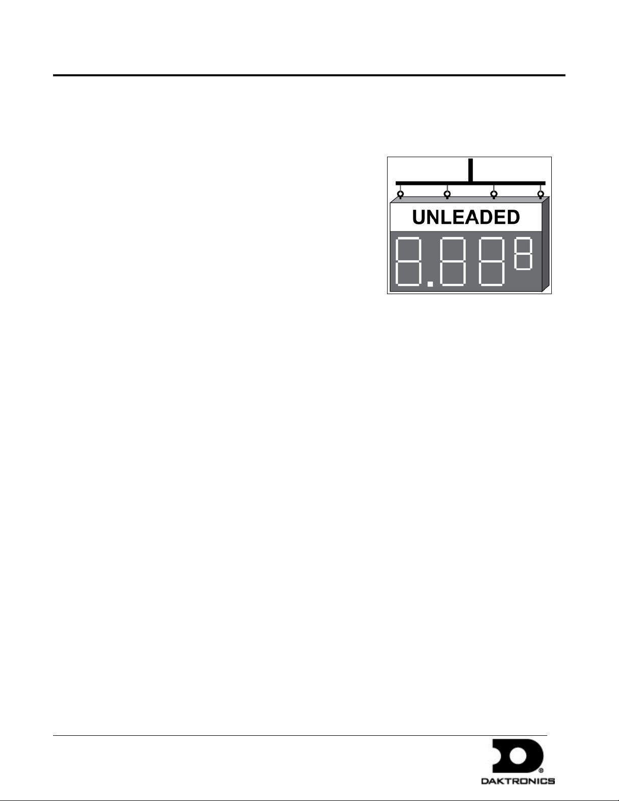
1. Use all eyebolts and a lift bar to lift the display into position on the
support structure, as shown in Figure 1.
Figure 1: Correct Lifting Procedures
2. Drill through the display cabinet to attach the mounting hardware.
3. Remove all metal shavings from the display.
4. If desired, remove the eyebolts.
5. Using silicone approved for use on aluminum, seal all holes on the display top.
6. Ensure the front of the display is not enclosed so it receives proper ventilation.
Note: Keep the display temperature below 140° F.
FL-2109 Displays
1. Lift the display into position on the support structure, as shown in Figure 1.
2. Weld or use
3. If desired, remove the eyebolts.
4. Using silicone approved for use on aluminum, seal all holes on the display top.
5. Ensure the front of the display is not enclosed so it receives proper ventilation.
3
/8" hardened bolts to secure all clip angles to the support structure.
Note: Keep the display temperature below 140° F.
12 September 2011
tel 605-697-4036 or 800-325-8766 fax 605-697-4700
www.daktronics.com
Page 2
FuellightTM Display Installation Quick Guide 2 of 2
PO Box 5128 201 Daktronics Dr Brookings SD 57006-5128
DD2109473 Rev 0
Connecting Power
1. Connect the earth-grounding wire the ground bar found in the
display. Fuellight
ohms or less.
2. Route 120 VAC power to the sign.
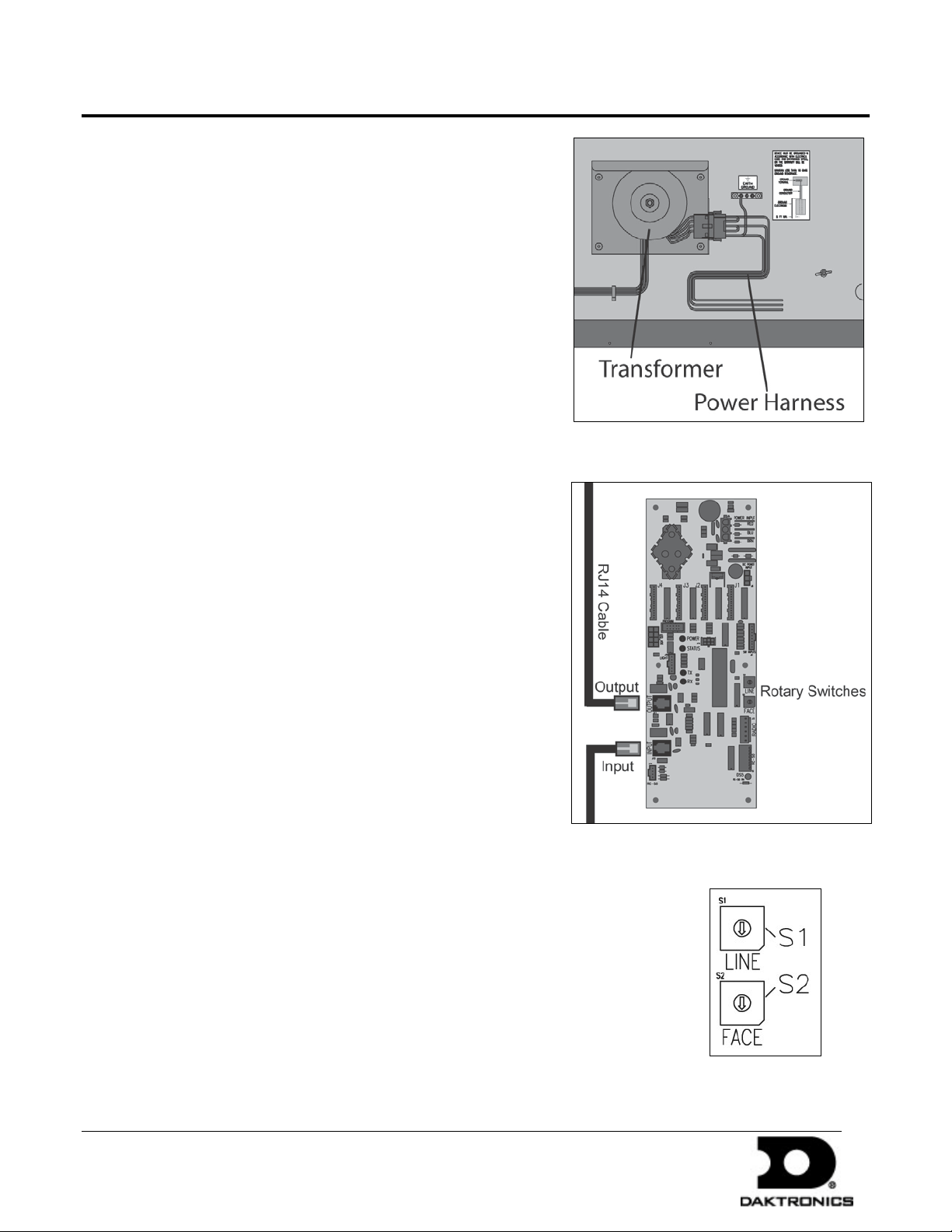
3. Connect 120 VAC power wires to the power harness that comes
from the transformer in each display, as shown in Figure 2.
Note: Displays can share a circuit with items on the same
structure provided the circuit is sized accordingly.
TM
displays require resistance-to-ground of 10
Communication Installation
1. Route the provided RJ11 cable from the output of one driver to
the input of the next driver, as shown in Figure 3.
2. Repeat Step 1 until all displays are connected.
Figure 2: Connecting Power and Signal
3. Set the display driver address for each display by turning the
rotary switches so they show the correct face and line based on
the location in the display. Displays set to the same line number
will show the same price. Refer to Figure 4.
Display Power Up
When booting up, the display goes through a self-test sequence.
When finished, E4 appears on the display which means no prices
have been set. Use the communication method to set the price for
each line.
Figure 3: Display Driver
12 September 2011
Figure 4: Rotary
Switches
tel 605-697-4036 or 800-325-8766 fax 605-697-4700
www.daktronics.com
 Loading...