

Page 1

Product 1279
d
Rev 2 – 15 March 2006
Please fill in the info hen
calling Daktronics for assist
Displa y Serial No. _____________________________________________
Installation and Operation Manual
Display Model No. _____________________________________________
ED-14305 Rev 2 – 20 March 2006
Date Installed _________________________________________________
DAKTRONICS, INC.
Copyright © 2003
All rights reserved. While every precaution has been taken in the preparation of this manual,
the publisher assumes no responsibility for errors or omissions. No part of this book covered
by the copyrights hereon may be reproduced or copied in any form or by any means – graphic,
electronic, or mechanical, including photocopying, taping, or information storage and retrieval
systems – without written permission of the publisher.
Daktronics
n
331 32
Ave PO Box 5128 Brookings SD 57006
tel 605-697-4036 or 877-605-1115 fax 605-697-4444
www.daktronics.com e-mail sales@daktronics.com
®
, DataMaster®, DataMaster™, and All Sport® are trademarks of Daktronics, Inc. All other
DataMaster® Outdoor LED
Lottery Displays
rmation below for your display; use it for reference w
ance.
Model DF-1060
trademarks used in this manual are the property of their respective owners.
ED-14305
Page 2

ED-14305
Product 1279
Rev 2 – 20 March 2006
Please fill in the information below for your display; use it for reference when
calling Daktronics for assistance.
Display Serial No. _____________________________________________
Display Model No. _____________________________________________
Date Installed _________________________________________________
DAKTRONICS, INC.
Copyright © 2003 - 06
All rights reserved. While every precaution has been taken in the preparation of this manual,
the publisher assumes no responsibility for errors or omissions. No part of this book covered
by the copyrights hereon may be reproduced or copied in any form or by any means – graphic,
electronic, or mechanical, including photocopying, taping, or information storage and retrieval
systems – without written permission of the publisher.
Daktronics
trademarks used in this manual are the property of their respective owners.
®
, DataMaster®, DataMaster™, and All Sport® are trademarks of Daktronics, Inc. All other
Page 3

Table of Contents
Section 1: Introduction....................................................................................1-1
1.1 How To Use This Manual..........................................................................1-1
1.2 Manual Overview...................................................................................... 1-2
1.3 Product Overview...................................................................................... 1-3
1.4 Model Identification .................................................................................. 1-4
1.5 Product Safety Approval ........................................................................... 1-4
1.6 Display Specifications............................................................................... 1-4
Section 2: Mechanical and Electrical Installation.........................................2-1
2.1 Mechanical Installation.............................................................................. 2-1
Lifting the Display.............................................................................. 2-1
2.2 Electrical installation.................................................................................2-2
Power.................................................................................................. 2-3
2.3 Power and Signal Connection.................................................................... 2-4
Host/Client Definitions and Address Settings....................................2-6
2.4 Modem Installation.................................................................................... 2-6
2.5 Radio Installation.......................................................................................2-7
2.6 Photosensor Installation.............................................................................2-8
Section 3: Display Maintenance and Troubleshooting................................3-1
3.1 Cabinet Specifications............................................................................... 3-1
3.2 Component Location and Access .............................................................. 3-1
Replacing a Digit................................................................................ 3-2
Replacing a Digit Segment................................................................. 3-3
Replacing a Driver.............................................................................. 3-4
3.3 Schematic ..................................................................................................3-4
3.4 LED Drivers .............................................................................................. 3-4
3.5 Segmentation and Digit Designation......................................................... 3-6
3.6 Troubleshooting.........................................................................................3-7
Power On Self-Test:...........................................................................3-8
3.7 Lightning Protection .................................................................................. 3-9
3.8 Replacement Parts ..................................................................................... 3-9
3.9 Daktronics Exchange and Repair and Return Programs.......................... 3-10
Section 4: Control System Overview.............................................................4-1
4.1 DataMaster 100 Overview......................................................................... 4-1
Replacement Parts List....................................................................... 4-2
4.2 Control System Overview..........................................................................4-2
Wire Control....................................................................................... 4-2
Modem and Radio Control.................................................................4-4
Table of Contents
i
Page 4

Section 5: Lottery Display Operation............................................................ 5-1
5.1
DataMaster Insert and Code ......................................................................5-1
5.2 Lottery Display Operation .........................................................................5-1
Lottery Display Startup ......................................................................5-2
Lottery Display Controller Operation.................................................5-2
Modifying Amount Settings ...............................................................5-3
Dimming.............................................................................................5-4
Display Sequence ...............................................................................5-5
Menu Items.........................................................................................5-6
Appendix A: Reference Drawings .....................................................................A-1
Appendix B: Supplementary EDs.....................................................................B-1
Table of Contents
ii
Page 5

Table of Figures
Figure 1: Daktronics Drawing Label.....................................................................................1-1
Figure 2: DF-1060-60 ........................................................................................................... 1-3
Figure 3: Lifting the Display................................................................................................. 2-2
Figure 4: DataMaster Driver Enclosure with 16-Column Driver.......................................... 2-5
Figure 5: Modem-to-Driver Connection............................................................................... 2-7
Figure 6: Light Sensor Installation........................................................................................ 2-8
Figure 7: Hinged Digit Panel................................................................................................ 3-1
Figure 8: Digit Installation.................................................................................................... 3-2
Figure 9: Digit Segments and Connectors............................................................................. 3-3
Figure 10: Digit Designation................................................................................................. 3-6
Figure 11: DataMaster 100.................................................................................................... 4-1
Figure 12: DataMaster 100 Controller with Signal Cable..................................................... 4-3
Figure 13: Wire Control from Building Location ................................................................. 4-3
Figure 14: DataMaster 100 Insert LL-2551 ..........................................................................5-1
List of Figures
i
Page 6

Page 7
Section 1: Introduction
This manual explains the installation of Daktronics® DataMaster® LED Lottery Displays and
provides details for display maintenance and operation. If you have questions regarding the
safety, installation, operation, or service of this system, contact Daktronics. Customer Service
Help Desk telephone numbers are listed on the cover page of this manual.
1.1 How To Use This Manual
Important Safeguards:
Read and understand these instructions before installing the d isplay.
Do not drop the control console or allow it to get wet.
Properly ground the display with a ground ing electrode at the sign location.
Disconnect power when the display is not in use.
Disconnect power when servicing the display.
Do not modify the display structure or attach any panels or coverings to the
scoreboard without the express written consent of Daktronics, Inc.
Listed below are a number of drawing types commonly used by Daktronics, along
with the information that each is likely to provide. This manual might not contain all
these drawings.
System Riser Diagrams: overall system layout from control room to the
display, power and phase requirements.
Shop Drawings: fan locations, mounting information, power and signal
entrance points and access method (front or rear).
Schematics: power and signal wiring for various components.
Component Placement Diagrams: locations of critical internal display
components such dual line controllers, line filters and power supplies.
Layout, Load Center and Signal Drawings: load center power
assignments and dual line controller signal assignments. These drawings
illustrate the origin of each module’s power and signal.
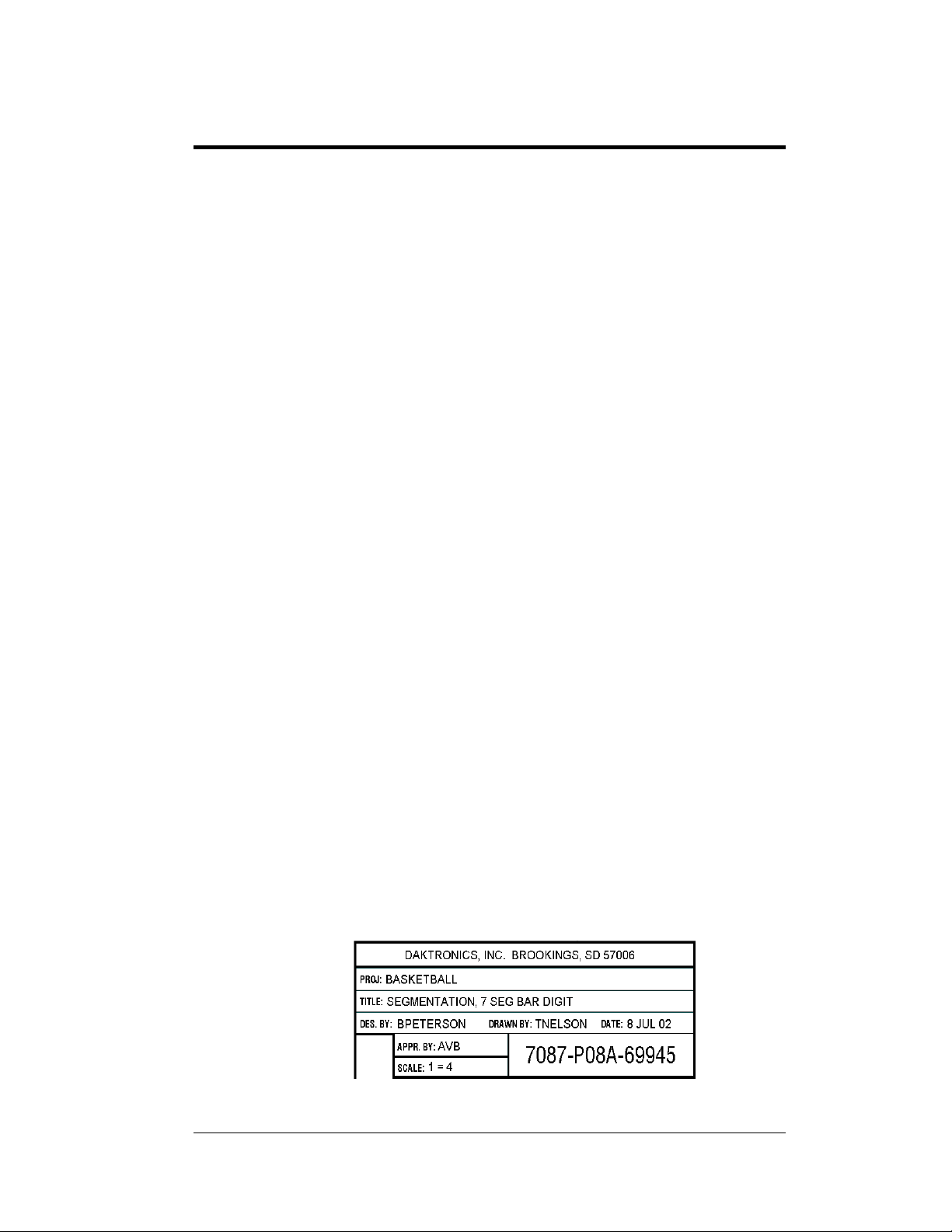
Figure 1 illustrates a Daktronics drawing label. The drawing number is located in
the lower-right corner of a drawing. This manual refers to drawings by the last set of
digits and the letter preceding them. In the example below, the drawing would be
referred to as Drawing A-69945.
Figure 1: Daktronics Drawing Label
Introduction 1-1
Page 8

All references to drawing numbers, appendices, figures, or other manuals are
resented in bold typeface, as in this example: “Refer to the Component Placement
p
Diagram, Drawing A-69945, in Appendix A for the power supply location.”
In addition, any drawings referenced within a p
beginning of that section. Drawings may be referenced by title or by title and
drawing number as in the following example:
Reference Drawing:
Component Placement Diagram, A-69945
Daktronics identifies manuals by the engineering document (ED) number located on
the cove
ED-14305.
Daktronics displays are built for long life and
from time to time, certain display components will need to be replaced. The
Replacement Parts List in Section 3.8 provides the names and part numbers of
components that may need to be ordered during the life of this display. Most display
components have a white label that lists the part number. The component part
number is in the following format: 0P-XXXX-XXXX (circuit board) or 0A-XXXXXXXX (multi-component assembly).
Following the Replacement Parts List is the
Section 3.9. Refer to these instructions if any display component needs repair or
replacement.
Please list the model number, display serial
operational in the spaces provided on the second page of this manual. When calling
Daktronics customer service, have this information available to ensure that your
request is serviced as quickly as possible.
r page of each manual. For example, this manual would be referred to as
articular section are listed at the
...................... Appendix A
require little maintenance. However,
Exchange/Replacement Procedure in
number and the date this display became
1.2 Manual Overview
This manual details large-size outdoor digit sets. It is divided into the following
sections:
Section I Intr
Section II
1-2 Introduction
oduction covers the basic information needed to make the
most of the rest of this manual. Take time to read the entire
introduction, because it defines terms and explains concepts
used throughout the manual. This section contains an
overview of the product, display specifications, product safety
information, and labeling and numbering descriptions.
Mechanical and Electrical Installation provides general
guidance on display mounting and terminating power and
signal cable at the display.
Page 9
Section III Maintenance and Troubleshooting addresses such things as
removing basic display components, troubleshooting the
display, performing general maintenance, and exchanging
display components.
Section IV Control System Overview describes the DataMaster
and system setup options.
Section V Lottery Display Operation provides complete instructions
for programming and operating the Lottery display.
Appendix A Reference Drawings contains all engineering drawings called
out in this manual.
Appendix B Supplementary Manuals contains additional information that
may be helpful in the operation and maintenance of the
display.
Daktronics recommends that you read all general sections before beginning
installation or operation.
1.3 Product Overview
™
100
The DataMaster Lottery models detailed in this manual are part of a family of
outdoor displays designed to offer simple installation, easy readability, and
reliability. Solid-state components and microprocessor control assure consistent
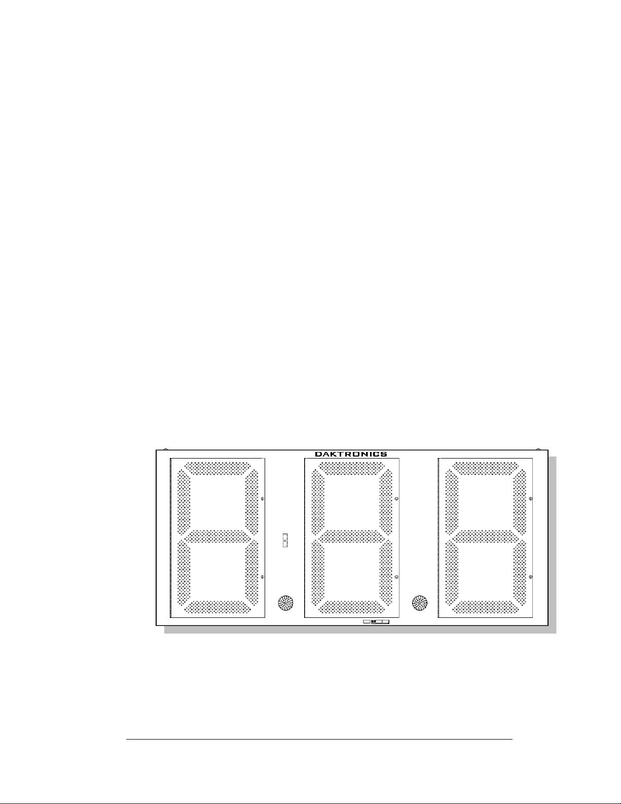
operation and accuracy. The three-digit Lottery sign is illustrated in Figure 2 below.
Figure 2: DF-1060-60
Intended for use in highway and city signs and billboards, the Lottery displays
include several models: DF-1060-60, DF-106 0-48, DF-1060-36 and DF-1060-24. All
have the same layout: three LED digits separated by LED decimals. They are
distinguished from one another by their overall size and by the height of their digits.
Introduction 1-3
Page 10

The displays use red or amber LEDs – light emitting diodes – to illuminate the digits.
Ds are tiny, solid-state components that use a semiconductor chip to transform
(LE
electrical current into light. They are high-intensity, low-energy lighting units.)
Because of their LED technology, the Lottery displays consume little power – barely
more than a household lamp. Maximum power usage for all three models in this
series is 300 W.
Cabinets for the displays are constructed of heavy-gauge aluminum. Cabinets are
typically black to m
Digit faceplates are black, and they are set directly into the cabinet surface.
Refer to Sec
specifications.
The Lottery displays have been designed for use with the Daktronics DataMaster
100 hand-held controller. The device uses a keypad overlay (called an insert) for
display control, and the Data Master displays themselves operate without
modification on All Sport
Daktronics software and the appropriate interface. Refer to Section 5 for complete
operating information.
tion 1.6 for a complete listing of weights, dimensions, and power
aximize LED contrast, but other cabinet colors are available.
®
5000 signal protocol. Other controllers may be used with
1.4 Model Identification
™
Daktronics displays are differentiated by their model numbers: For example, with
Model DF-1060, the two-letter prefix DF- identifies it as a Data Master Lottery
display. The next four numbers, 1060, identify the specific model.
DF- se
ries displays are further identified with a suffix of -36, -48, or -60, indicating
nominal digit size in inches: DF-1060-48 describes a Data Master Lottery display
with 48" digits.
Finally, the DF-
amber LED digits: DF-1060-36-R.
model names may include the letters “R” or “A”, indicating red or
1.5 Product Safety Approval
Daktronics outdoor LED displays are ETL-listed and tested to CSA standards.
ontact Daktronics with any questions regarding the testing procedures.
C
1.6 Display Specifications
Reference Drawings:
Mechanical Specs, DF-1060-36
Mechanical Specs, DF-1060-48
Mechanical Specs, DF-1060-60
Mechanical Specs, DF-1060-24
Specifications for each of the three lottery di
listed above, in the electrical specification drawings, and in the following table.
.................................. Drawing A-195399
.................................. Drawing A-195339
.................................. Drawing A-195343
.................................. Drawing A-240357
splay models are shown the drawings
1-4 Introduction
Page 11

DataMaster DF-1060 Lottery Displays
Note: Each display requires a dedicated 15 A, 120 V AC line.
Model Dimensions
Height, Width, Depth
DF-1060-60 H6’-0", W12'-0", D8"
(1829 mm, 3658 mm, 203 mm)
DF-1060-48 H4’-6", W10’-0", D8"
(1372 mm, 3048 mm, 203 mm)
DF-1060-36 H3’-6", W7’-6", D8"
(1067 mm, 2286 mm, 203 mm)
DF-1060-24 H5’-0”, W2’-6”, D6 1/8”
(1524mm, 720mm, 155mm)
Weight
Uncrated
Crated
350 lb
(160 kg)
560 lb
(254 kg)
200 lb
(91 kg)
320 lb
(145 kg)
140 lb
(64 kg)
224 lb
(102 kg)
60 lb
(27 kg)
100 lb
(45 kg)
Digit Size
Digit Color
Maximum
Wattage
Power
Amps
per
Line
(Single
Phase)
60" (1524 mm)
Red or amber
48" (1219 mm)
Red or amber
36" (914 mm)
Red or amber
24” (610 mm)
Red or Amber
300 W
300 W
300 W
150 W 120 V AC 1.3 A
120 V AC
120 V AC
120 V AC
2.5 A
2.5 A
2.5 A
Introduction 1-5
Page 12

Page 13

Section 2: Mechanical and Electrical
Installation
Mechanical installation typically consists of installing concrete footings and steel beams and
mounting the display and any accompanying panels to the beams.
Electrical installation consists of the following processes:
Providing power and ground to a disconnect near the display.
Routing power and ground from the main disconnect to the display driver/power
enclosure.
Connecting the display ground to a grounding electrode at the sign location.
Routing the control signal cable from the control location to the sign location.
2.1 Mechanical Installation
Reference Drawings:
Mounting Method, Flag Style, One Pole
Mounting Method, Single Li
While Data Master outdoor digit displays are designed for wall or pole mounting, every
installation wil
method. Most DataMaster models have finished exteriors, for example, but other
models are designed to be inserted into an existing sign cabinet and require a custom
installation. Lottery displays have a fully finished cabinet, but they are designed to be
used as part of larger sign or billboard.
The engineering drawings referenced above describe several mounting methods, from a
si
ngle display on a single column support to multiple displays stacked above one
another in a two-pole installation. The drawings include welding and hardware notes
that will be applicable for most installations.
Note: T
specifications for construction. The actual mounting hardware and structural design
must be specified by a qualified engineer.
l be different. Actual site demands will dictate the appropriate mounting
he drawings suggest mounting methods and are not to be considered as
ne on One Pole................Drawing A-166142
......................Drawing A-166139
Lifting the Display
DataMaster Lottery displays are shipped equipped with 1/2" eyebolts that are used for
lifting and positioning the modules. Eyebolts are located along the top outer edges of
the cabinet.
Daktronics strongly recommends using a spreader bar, or lifting bar, to lift the
display. Using a
minimizing lifting stress.
Mechanical and Electrical 2-1
Specifications
spreader bar ensures that the force on the eyebolts is straight up,
Page 14
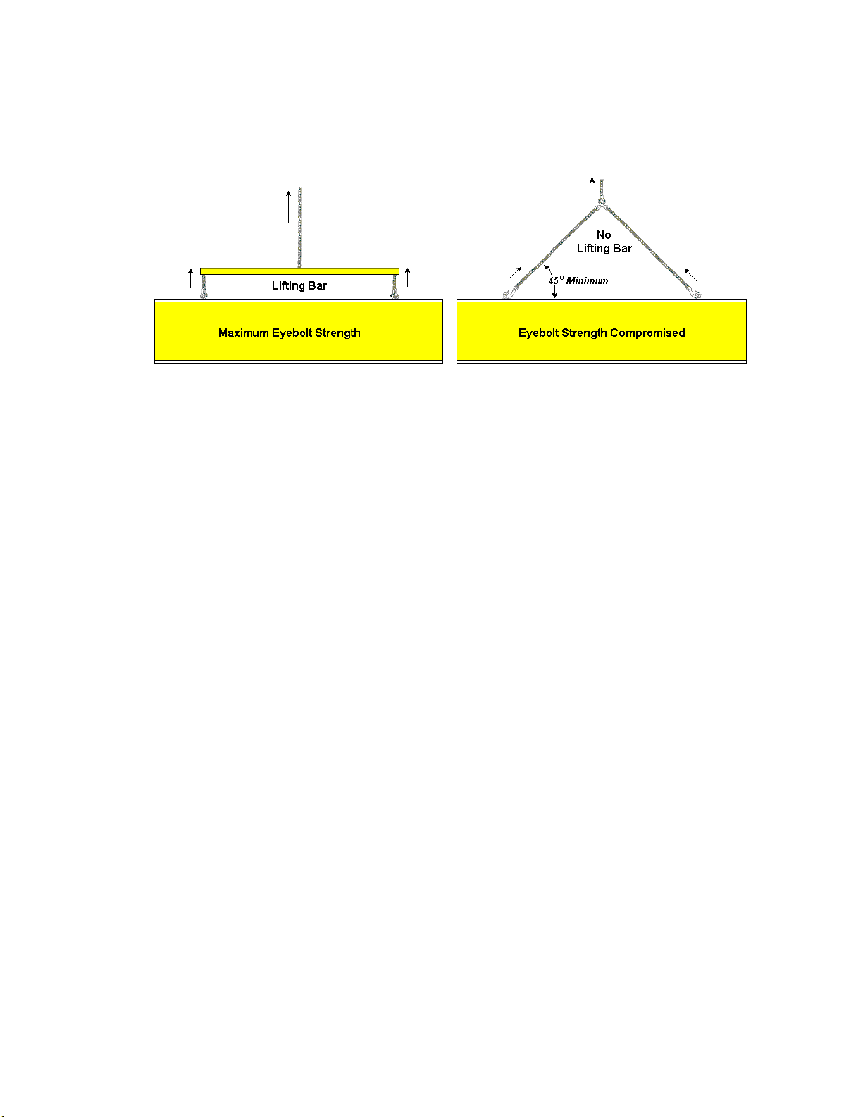
Figure 3, below, illustrates two lifting methods. The illustration shows both the
preferred method (left example) and an alternative method (right example) for lifting
a display. Be sure to use every lifting point provided.
Figure 3: Lifting the Display
Eyebolts are intended for lifting during installation only. Do not attempt to
permanently support the display by the eyebolts.
Note: Daktronics assumes no liability for display damage resulting from incorrect
setup or incorrect lifting methods.
In installations in which an ad panel or some other display section may be added to
the base display, the lower section is installed first and secured to the support beams,
and then the upper section is placed atop or above the lower sign section and
attached to the beams. There may be cables extending from the top of the lower
section. Guide these cables into the hole in the bottom of the upper section for later
connection.
Installers may remove the lift eyebolts once the display is in place. Inspect the top
and sides of the display for any holes or openings that may allow moisture to enter
the display, and plug and seal those openings with silicone or another waterproofing
sealant.
2.2 Electrical installation
Electrical installation consists of the following processes:
Providing power and ground to a disconnect near the display.
Routing power and ground from the main disconnect to the display
driver/power enclosure.
Connecting the display ground to a grounding electrode at the sign location.
Routing the control signal cable from the control location to the sign
location.
Note: Only qualified individuals should perform power routing and termination to
the display. It is the responsibility of the electrical contractor to ensure that all
electrical work meets or exceeds local and national codes.
2-2 Mechanical and Electrical
Specifications
Page 15

Power
Reference Drawing:
Schematic; 16 Col Multipurpose LED Drvr..................Dra
Daktronics DataMaster displays have been designed for easy access to components,
and the power and control signal hookup has been simplified. Front panels are
hinged to allow access to the digits, cabling, and other electronic components.
Correct power installation is imperative fo
r proper display operation. The
subsections that follow give details of display power installation. Only qualified
individuals should attempt to complete the electrical installation; untrained personnel
should not attempt to install these displays or any of the electrical components.
Improper installation could result in serious damage to the equipment and could be
hazardous to personnel.
DataMaster outdoor displays require a dedicated, 120 V circuit for incoming power.
Th
e display itself has no breakers or fuses.
WARNING: It is critical th
at the display circuit be fused at 15 A, and that all
conductors used must be designed to pass a 15 A current in normal operation. Failure
to meet wiring and overcurrent protection device requirements is a violation of the
National Electrical Code
®
and will void the display warranty.
Refer to the DataMaster display schematic listed above and to the chart in Section 2
t
o determine circuit specifications and maximum power requirements for the models
described in this manual.
wing A-179599
Grounding
Reference Drawings:
Schematic; 16 Col Multipurpose LED Drvr..................Dra
Reference, Driver Enc
Displays MUST be grounded according to the provisions outlined in Article 250 of
the National Electrical Code and according to the specifications in this manual.
Daktronics recommends a resistance-to-ground of 10 ohms or less.
The contractor performing the electrical installation can verify ground resistance.
Tech
nicians from Daktronics Sales and Service offices can also provide this service.
The display system must be
Proper grounding is necessary for reliable equipment operation. It also protects the
equipment from damaging electrical disturbances and lightning. The display must be
properly grounded, or the warranty will be void. Refer to the schematic, Drawing
A-179599, for information on connecting the grounding wire. The driver enclosure
terminal block, the location of the grounding connector, is illustrated in Drawing A-
182708.
wing A-179599
losures......................................Drawing A-182708
connected to an earth electrode installed at the display.
Mechanical and Electrical 2-3
Specifications
Page 16

The material for an earth-ground electrode diffe
rs from region to region and may
vary according to conditions present at the site. Consult the National Electrical Code
and any local electrical codes that may apply. The support structure of the display
cannot be used as an earth-ground electrode. The support is generally embedded in
concrete, and if it is in earth, the structural steel is usually primed or it corrodes,
making it a poor ground in either case.
Power Installation
There are two considerations for power installatio
n: installation with ground and
neutral conductors provided, and installation with only a neutral conductor provided.
These two power installations differ slightly, as described in the following
paragraphs:
Installation with Ground and Neutral Conductors Provided. For this type of
in
stallation, the power circuit must contain an isolated earth-ground cond uctor. In
this circumstance, do not connect neutral to ground at the disconnect or at the
display. This would violate electrical codes and void the warranty. Use a disconnect
so that all hot lines and neutral can be disconnected. The National Electrical Code
requires the use of a lockable power disconnect within sight of or at the display.
Installation with Only a Neutral Conductor Provided. Installatio
ns where no
grounding conductor is provided must comply with Article 250-32 of the National
Electrical Code. If the installation in question meets all of the requirements of Article
250-32, the following guidelines must be observed:
• Connect the
grounding electrode cable at the local disconnect, never at the
display driver/power enclosur e.
• Use a
disconnect that opens all of the ungrounded phase conductors.
2.3 Power and Signal Connection
Reference Drawings
Quick Install, DF-1060 Lottery Displays
Schematic; 16 Col Multipurpose LED Drvr.................. Dra
16 Col. MASC Driver Spec
ification.............................. Drawing A-184475
Route power and signal cables into the displ
knockouts for
1
/2" conduit fittings on the sides of all DataMaster cabinets and on the
back panels. All power and signal wiring terminates at the driver enclosure.
Refer to Drawing A-198033
for a complete review of power and signal connections
for DataMaster Rate displays. Drawing A-184475 illustrates and provides
connection specifications for the 16-column driver used in all DataMaster Lottery
displays. The schematic for the driver details both the wiring in the enclosure and
external connections to the display. Power and signal connections are illustrated in
Figure 4.
2-4 Mechanical and Electrical
Specifications
...................... Drawing A-198033
wing A-179599
ay from the side or rear. There are
7
/8"
Page 17
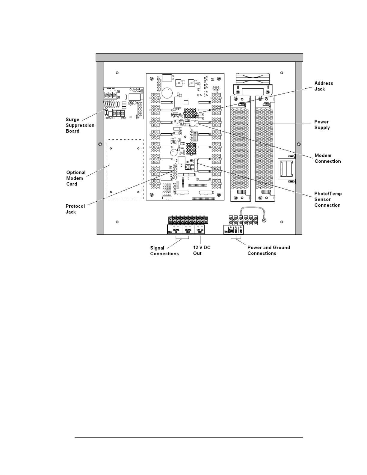
Figure 4: DataMaster Driver Enclosure with 16-Column Driver
To gain access to the driver enclosure, open the access door and remove the cover
from the enclosure. Refer to the electrical specifications drawings for the access
location for your sign.
Connect the power and signal cables at the appropriate locations on the driver
enclosure panel, shown in Figure 4 and in Drawing A-198033.
The power feeder circuit connects directly to a terminal block in the driver enclosure.
The block is located in the bottom center of both types of driver enclosure. Refer to
the driver illustrations and the schematics, Drawings A-184475 and A-179599, for
wiring details.
Route signal cabling to the terminal block on the lower left edge of the enclosure
(see Figure 4). The connections are labeled to permit easy installation. (In the 16column enclosure, the signal block is at bottom center.) For signal cable, Daktronics
recommends 2-pair shielded cable, 22 AWG (Daktronics part number W-1234).
Mechanical and Electrical 2-5
Specifications
Page 18

Host/Client Definitions and Address Settings
Reference Drawings:
Host/Client Definitions
16 Col. MASC Driver Spec
In sign systems with multiple displays, one driver at each sign installation is
designated as the “host driver.” This driver receives its signal directly from the
controller on the Signal In terminals, and it is the only driver that is connected to the
photo/temp sensor. The Signal Out terminals are used to connect to “client drivers.”
Refer to Drawing A-185236 for an illustration of the client/host driver display
setups.
Select the host driver by inserting the Protocol 4 plug into the 5-pin protocol jack
(J2
0.) Refer to Drawing A-184475.
The 12 V DC terminals connected to the host driver (see
Figure 4) run to the controller junction box. This output is used to power the
DataMaster 100 controller.
All other drivers in the display system are client drivers.
from the host driver on the Signal In terminals and can re-drive this signal to other
“client drivers” on the Signal Out terminals.
The address of each driver is set using t
is based on that driver's position in the sign or display system. If a single-line sign is
used, the address will typically be address “1.” This is the default address plug that is
shipped with each display. In a multiple-sign display, the address plug determines
which line of information is shown on the drivers' digits. The address plug for each
line is included in the address plug kit, if applicable.
........................................... Drawing A-185236
ifications ..................... Drawing A-184475
“Signal Connections” in
These drivers receive signal
he address jack (J19), and the address setting
2.4 Modem Installation
Reference Drawing:
Modem Installation, MASC Driver Enclosure.....................Dra
In most instances, DataMaster Lottery displays will be controlled by modem.
Typ
ically, modems and cabling will be factory-installed and ready to operate.
In the event that a modem must be field installed, refer to the 16
Drawing A-194873, and follow these steps:
1. Mak
e sure the power to the display is off.
2. Th
e modem mounts on four standoffs to the left of the driver. Position the
card on the standoffs and secure it with the hardware provided.Plug in the
RJ-45 end of the modem cable to the J6 connector as shown in Figure 5.
Plug the RJ-11 end of the cable into the J24 jack on the driver.
3. Pl
ug in the 12-volt power source, P3, to the J3 connector on the modem
card.
2-6 Mechanical and Electrical
Specifications
wing A-194873
-Col Driver detail on
Page 19

4. Connect the incoming phone line to the modem on J5, or wire the line to
TB2, Tip and Ring inputs.
5. Turn the display power on, and test the installation.
Figure 5: Modem-to-Driver Connection
2.5 Radio Installation
The Data Master radio permits control of any DataMaster display without the use of
a direct-wired connection between the DataMaster 100 and the display. Because the
radio is optional with DataMaster displays, the receivers and transmitters must be
field-installed. Please refer to the DataMaster Radio Installation Manual,
ED-13894, for complete details on installation and setup for a bidirectional radio
system.
Mechanical and Electrical 2-7
Specifications
Page 20
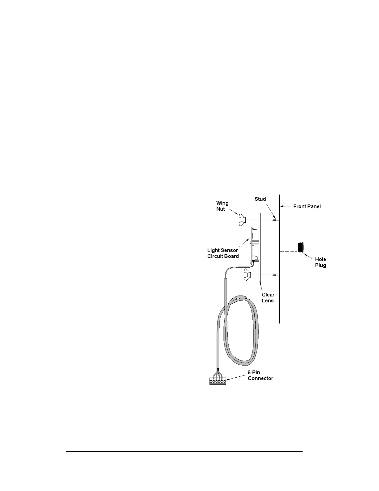
2.6 Photosensor Installation
Reference Drawings:
Light Sensor Installation, G3....................................... Drawing A-183775
Electrical Specs, DF-1060-60...................................... Drawing A-194930
Electrical Specs, DF-1060-48...................................... Drawing A-195339
Electrical Specs, DF-1060-36...................................... Drawing A-195398
Displays in the DataMaster series use a photosensor to regulate sign dimming
functions. (Dimming involves decreasing overall display intensity, both for better
display viewing and to prolong LED life. The brightness level should be highest
during the day to compete with daylight, and lower at night.)
The light sensor is typically installed at the factory. However, if field installation is
necessary, use Drawing A-183775 and the following instructions to mount the photo
sensor in your DataMaster Rate display. If the sign or sign system has more than one
display, install the light sensor in the host display only.
1. Unfasten the latch screws on
the middle digit and open the
hinged access door. The light
sensor will be mounted to the
panel between the first and
second digits. The exact
location will be shown on each
of the electrical specifications
drawings listed above.
2. Locate and remove the
plastic plug from front panel of
the display, as shown in
Figure 6. The location of the
plug varies by model. Refer to
the mechanical specifications
drawings for model-specific
information.
3. There are two 6-32 studs above
and below the plughole.
Position the internal light
sensor assembly on the studs,
with the clear lens toward the
front of the cabinet and the
cable at the bottom. Secure the
sensor with the plastic wing
nuts provided with the
assembly kit.
5
/8"
Figure 6: Light Sensor Installation
2-8 Mechanical and Electrical
Specifications
Page 21

ute the signal cable to the driver and insert the 6-postion plug into the
4. Ro
mating jack on the driver, TB1.
5. Close the
hinged access doors and tighten the latch screws.
Mechanical and Electrical 2-9
Specifications
Page 22

Page 23

Section 3: Display Maintenance
and Troubleshooting
IMPORTANT NOTES:
1. Disconnect power before doing any repair or maintenance work on the
display!
2. Allow only qualified service personnel to access internal display
electronics.
3. Disconnect power when not using the display.
3.1 Cabinet Specifications
Cabinets for the Daktronics outdoor LED digit displays are constructed of heavygauge aluminum. Exact dimensions and weights for each model are listed in the
specifications table in Section 2. Hinged panels for servicing digits and indicators
and for component access are detailed in each model's mechanical specifications
drawing.
3.2 Component Location and Access
Reference Drawings:
Electrical Specs, DF-1060-60......................................Drawing A-194930
Electrical Specs, DF-1060-48......................................Drawing A-195339
Electrical Specs, DF-1060-36......................................Drawing A-195398
For the front-access displays in this series, all internal
electronic components and digits can be reached by
opening the hinged access doors on the front of the
display. Each door swings outward when the latch
screws on the display face panel are unfastened. The
latches, shown in Figure 7, require a quarter-turn.
In each of the DF-1060 models, the driver enclosure
is located immediately behind the center digit. For
front and opened views of the displays, refer to your
model's electrical specifications drawings, listed
above.
Note: Disconnect power before servicing the display!
Disconnect power, too, when the display is not in
use. Prolonged power-on may shorten the life of
some electronic components.
Figure 7: Hinged Digit Panel
Display Maintenance 3-1
and Troubleshooting
Page 24

Replacing a Digit
The digit circuit board, the platform for the LEDs, is mounted to the back of the digit
panel. Do not attempt to remove individual LEDs. In the case of a malfunctioning
board, replace the entire digit panel. Refer to Figure 8 below.
To remove a display digit, follow these steps:
1. Open the digit panel as described in the preceding section.
Figure 8: Digit Installation
2. Disconnect the connector from the back of the digit. Release the connector
by squeezing together the locking tabs as you pull the connector free.
3. The digits are secured to the inside of the panel with fixed machine screws,
spacers, and push nuts. Remove the nuts and lift the digit off the standoff
screws. (The push nuts can be removed in several ways, but Daktronics
recommends using a
9
/32" nut driver.)
4. Position a new digit over the screws and replace and tighten the nuts.
5. Reconnect the power/signal connector.
Note: This is a keyed connector B it will attach in one way only. Do not
attempt to force the connection!
6. Close and secure the digit panel and test the display.
3-2 Display Maintenance
and Troubleshooting
Page 25

Replacing a Digit Segment
When a digit malfunctions, in most cases it is necessary to replace the entire digit
circuit board. Some larger digits (36", 48", 60"), however, are constructed in
segments, as shown in Figure 9, and it may be possible to make repairs by removing
only the defective segment. As with smaller digits, the digit segment circuit boards
are mounted to the back of the digit panel. Do not attempt to remove individual
LEDs.
To remove a digit segment, follow these steps:
1. Open the digit panel as described
2. Disconnect the 2-pin or 4-pin
3. The individual segments are
4. Position a new segment over the
5. Reconnect the power/signal connector.
6. Close and secure the digit panel and test the display.
Replace a malfunctioning decimal in the same manner.
above.
connector from the back of the
individual segment. Release the
connector by squeezing together
the locking tabs as you pull the
connector free.
secured to the inside of the panel
with fixed machine screws,
spacers, and push nuts. Remove
the nuts and lift the segment off
the standoff screws.
Figure 9: Digit Segments and Connectors
screws and replace and tighten the nuts.
Note: This is a keyed connector B it will attach in one way only. Do not
attempt to force the connection!
Display Maintenance 3-3
and Troubleshooting
Page 26

Replacing a Driver
Drivers are mounted inside the display and immediately behind a digit, and with the
Lottery displays, the driver enclosure is located immediately behind the center digit.
Each driver is enclosed with a power suppl
Before a failed driver can be reached, the enclosure must be accessed. Follow these
steps:
1. Open the digit panel or display face panel as described in Section 3.2.
2. Remove the cover from the driver enclosure.
3. Disconnect all connectors from the driver. Release each connector by squeezing
together the locking tabs as you pull the connector free.
Note: Wh
attach in one way only. Do not attempt to force the connections.
en reconnecting, remember that these are keyed connectors and will
4. Remove the screws, nuts, or wing nuts securing the driver to the inside of the
enclosure.
5. Carefully lift the driver from the display and place it on a clean, flat surface.
6. Follow steps 1 through 5 in reverse order to attach a new driver.
y and power and signal terminal blocks.
3.3 Schematic
Reference Drawing:
Schematic; 16 Col Multipurpose LED Drvr.................. Dra
Drawing A-179599 is t
Data Master Lottery displays. The schematic includes power and signal inputs and
all wiring for the models described in this manual.
3.4 LED Drivers
Reference Drawing:
16 Col. MASC Driver Spec
In the display, the LED driver performs the task of switching digits on and off. Refer
to
Drawing A-184475 for a complete listing of driver connector functions and
wiring pin numbers.
All Data Master Lottery displays use 16-column drivers, and each driver has 20 or
m
ore connectors providing power and signal inputs to the circuit, and outputs to the
digits and indicators. The following table describes connector functions for a 16column driver.
wing A-179599
he schematic diagram for the 16-column driver used in the
ification.............................. Drawing A-184475
3-4 Display Maintenance
and Troubleshooting
Page 27

16-Column LED Driver
Connector No. Function
J1 – 16 Outputs to digits
J17 Power and signal input
J18 Relay
J19 Address
J20 Protocol
J21-22 ISP
J23 12 V DC out
J24 Modem
J28 Switch inputs
TB1 CAN (photo/temp sensor)
Output connectors 1 through 16 each have nine pins. Pin 7 provides power (hot) to
the digit or indicators wired to that connector. The other eight pins provide switching
connections.
The display line controlled by the driver is set with jumper wires in the 12-pin
address plug inserted in jack J19. All DataMaster displays ship with a “Line 1” plug
installed.
Display Maintenance 3-5
and Troubleshooting
Page 28

3.5 Segmentation and Digit Designation
Reference Drawing:
Segmentation, 7 Segment Bar Digit.............................. Drawing A-38532
In each digit, certain LEDs always go on and off together. These groupings of LEDs
are referred to as “segments.” Drawing A-38532 illustrates digit segmentation. It
also details which connector pin is wired to each digit segment and the wiring color
code used throughout the display.
The electrical specifications drawings listed in Section 3.2 specify the driver
connectors controlling the individual digits. Numbers displayed in hexagons in the
upper half of each digit, as shown in Figure 10, indicate which connector or
connectors are wired to that digit. The larger digits, 48" and 60", a re each wi red to
four connectors; while 36" digits have only two connectors.
Figure 10: Digit Designation
3-6 Display Maintenance
and Troubleshooting
Page 29

3.6 Troubleshooting
This section lists potential problems with the display, indicates possible causes, and
suggests corrective action. This list does not include every possible problem, but it
does represent some of the more common situations that may occur.
Symptom/Condition Possible Cause
Garbled display
Digit will not light
Segment will not light
Segment stays lit
Data appears in the wrong place
on the display, wrong data on a
lar line of the display
particu
Internal dr
Contro
Black
Poor contact at
Driver malfunction
Broken LE
Driver shift reg
Broken
Poor contact at
Driver shift reg
Short circuit on
Incorrect addr
(Refer to “Power On Self-Test” in the
following section, and consult tables to set
correct addresses.)
iver logic malfunction
l console malfunction
wire to digit broken
driver connection
D or connection
ister failure
wire between driver and digit
driver connector
ister failure
digit
ess settings on drivers
Some DataMaster displays have their own built-in troubleshooting mechanism.
Failu
res that may occur in the display driver are described using codes. In the event a
sign malfunctions, a failure code registers by displaying an “Ex” value on the first
two digits of the display. “E” simply indicates an error, and the letter “x” represents
the actual code number. Refer to the following table for a description of each failure
code and for possible solutions. Not all error codes are applicable to all displays.
Note: Th
e LCD screen on the DataMaster 100 controller will not show the failure
codes described in the following table. Failure codes will be displayed only on the
Data Master sign.
Display Maintenance 3-7
and Troubleshooting
Page 30

Failure Code Description Possible Solution
E1 Protocol Setting Error: There is an
unsupported driver protocol
setting.
E2
(Not applicable
to Lottery displays)
E3
(Not applicable
to Lottery displays)
E4 No Message Error: This code is
E5 No Line Number Selected Error:
Time Error: There is no valid time
stored in the driver; it may be a
failure of the real-time clock on
board or other timekeeping
device.
Temp Error: There is no response
from the temp sensor, or general
temp sensor failure.
shown when there are no
messages downloaded to the
display
The driver for this line has a
Protocol 4 plug installed in J20,
but there is no address plug
installed in J19.
Check the value set in the protocol
plug of the driver (J20).
Set the time in the display using the
Set Time menu option on the
DataMaster 100 controller.
Check the temp sensor location
and verify all connections. Refer to
the instruction sheet for the CAN
Temperature/Light Sensor
mounting, ED-13364.
Note: The temp sensor takes
approximately 10 seconds to
initialize on power-up. The sign will
display this error until initialization is
complete.
Download a new message to the
display using the <
SEQUENCE
100 controller.
Set the line number by installing the
correct plug in J19. The Protocol 4
plug designates this driver as the
“host.” If this is not the host, remove
the Protocol 4 plug from J20.
> key on the DataMaster
DISPLAY
Power On Self-Test:
A useful troubleshooting tool is the power on self-test the host driver performs every
time it powers up:
If the signal wiring between each controller is correct, the first two digits of
each driver will display “Ad” momentarily, and the first digit will then flash
three numbers indicating the decimal address that is set with the address
plug in J19. (If a client driver displays “A <number>,” followed by “P
<number>,” it is not receiving “signal in,” and is performing its own selftest.)
3-8 Display Maintenance
and Troubleshooting
Page 31

Nex
t, the first two digits of each line will display “Lx”, where “x” is the line
number that the driver is set to control (set with address plug).
Finally, each line
will display “1234…” according to the column number of
each of its digits. Every line should show “1” on the left-most digit, and all
digits should be numbered consecutively from left to right. If this is not the
case, either the wrong address plug is installed, or the driver or digit harness
is connected incorrectly.
If there is no address plug in the host driver,
client drivers will continually cycle through the power on self-test.
3.7 Lightning Protection
The use of a disconnect near the display to completely cut all current-carrying lines
significantly protects the circuits against lightning damage. The National Electrical
Code also requires it. In order for this device to provide protection, the power must
be disconnected when the display is not in use. The control console should also be
disconnected from power and from the signal j-box when the system is not being
used. The same surges that may damage the display's driver can also damage the
console's circuit.
the host driver will display “E5,” and all
3.8 Replacement Parts
Refer to the following table for Daktronics replacement parts.
Description Daktronics Part
Driver; enclosed, 16-col MASC 0A-1279-0176
Driver (only); 16-col, MASC, LED, coated 0P-1192-0086
Power supply; 24 V, 150 W, 86-132 V input A-1720
Fan; 32 cfm, 24 V DC, 3.15 in sq B-1030
Surge board with radio conn, outdoor 0P-1110-0011
Light sensor, G3 0A-1279-0203
Sensor (only); CAN temp and light detector,
coated w/ bus term
Digit half-segment, 60" red, horizontal, G3 0P-1192-0280
Digit half-segment, 60" red, vertical, G3 0P-1192-0281
Digit half-segment, 60" red, horizontal, G3 0P-1192-0282
No.
0P-1247-0002
Digit half-segment, 60" red, vertical, G3 0P-1192-0283
(Continued on next page)
Display Maintenance 3-9
and Troubleshooting
Page 32

(Continued from preceding page)
Description Daktronics Part
No.
Digit segment, 48" red vert 0P-1192-0212
Digit segment, 48" red horiz 0P-1192-0213
Digit segment, 48" amber vert 0P-1192-0226
Digit segment, 48" amber horiz 0P-1192-0227
Digit segment, 36" red vert 0P-1192-0208
Digit segment, 36" red horiz 0P-1192-0209
Digit segment, 36" amber vert 0P-1192-0222
Digit segment, 36" amber horiz 0P-1192-0223
Digit segment, 24” red vert 0P-1192-0204
Digit segment, 24” red horiz 0P-1192-0204
Digit segment, 24” amber vert 0P-1192-0218
Digit segment, 24” amber horiz 0P-1192-0219
Indicator, 4" circular red, pc board, G3 0P-1192-0244
Indicator, 4" circular amber, pc board, G3 0P-1192-0245
Address plug; AS shot clock, Address No. 1 0A-1150-0122
Plug; protocol 4 0A-1279-0089
Signal converter w/modem; 232-422, coated 0P-1279-0003
DataMaster 100 installation kit; indoor wired 0A-1279-0103
3.9 Daktronics Exchange and Repair and Return Programs
To serve customers' repair and maintenance needs, Daktronics offers both an
Exchange Program and a Repair and Return Program. Daktronics' unique Exchange
Program is a quick, economical service for replacing key components in need of
repair. If a component fails, Daktronics sends the customer a replacement, and the
customer, in turn, sends the failed component to Daktronics. This not only saves
money but also decreases display downtime.
Daktronics provides these plans to ensure users get the most from their Daktronics
p
roducts, and it offers the service to qualified customers who follow the program
guidelines explained below. Please call the Help Desk – 877-605-1115 – if you have
questions regarding the Exchange Program or any other Daktronics service.
3-10 Display Maintenance
and Troubleshooting
Page 33

When you call the Daktronics Help Desk, a trained service technician will work with
ou to solve the equipment problem. You will work together to diagnose the problem
y
and determine which exchange replacement part to ship. If, after you make the
exchange, the equipment still causes problems, please contact our Help Desk
immediately.
If the replacement part fixes the problem, package
the defective part in the same box
and wrapping in which the replacement part arrived, fill out and attach the enclosed
UPS shipping document, and RETURN THE PART TO DAKTRONICS. In most
circumstances, you will be invoiced for the replacement part at the time it is shipped.
This bill is due when you receive it.
Daktronics expects immediate return of an exchange part if it does not solve the
problem
. The company also reserves the right to refuse equipment that has been
damaged due to acts of nature or causes other than normal wear and tear.
If the defective equipment is not shipped to Daktronics within 30 working days from
th
e invoice date, it is assumed you are purchasing the replacement part, and you will
be invoiced for it. This second invoice represents the difference between the
exchange price and the full purchase price of the equipment. The balance is due
when you receive the second invoice. If you return the exchange equipment after 30
working days from the invoice date, you will be credited for the amount on the
second invoice, minus a restocking fee.
To avoid a restocking charge, please retur
n the defective equipment within 30
days from the invoice date.
Daktronics also offers a Repair and Return program for items not subject to
excha
nge.
Return Materials Authorization: To
return parts for service, contact your local
representative prior to shipment to acquire a Return Material Authorization (RMA)
number. If you have no local representative, call the Daktronics Help Desk for the
RMA. This expedites repair of your component when it arrives at Daktronics.
Packaging for Return: Packag
e and pad the item well so that it will not be damaged
in shipment. Electronic components such as printed circuit boards should be installed
in an enclosure or placed in an antistatic bag before boxing. Please enclose your
name, address, phone number and a clear description of symptoms.
Display Maintenance 3-11
and Troubleshooting
Page 34

This is how to reach us:
Mail: Custom
er Service
Daktronics, Inc.
PO Box 5128
331 32nd Ave
Brookings SD 57006
Phone:
Daktronics Help Desk: 877-605-1113 (toll free)
or 605-697-4034
Fax: 6
05-697-4444
E-mail: h
elpdesk@daktronics.com
3-12 Display Maintenance
and Troubleshooting
Page 35

Section 4: Control System Overview
This section describes the DataMaster 100 and includes the following subsections:
DM-100 Controller Overview identifies the control equipment, lists replacement
parts, and describes how the DM-100 operates the displays.
Control System Overview reviews the main options for display control.
4.1 DataMaster 100 Overview
Reference Drawing:
Riser Diagram, Outdoor Wire Control..........................Drawing A-164988
The DataMaster
shown in Figure 11, is a hand-held
controller designed to operat e
Daktronics LED Data Master
This lightweight controller, 6
1
by 4
/4" wide, is encased in ABS
plastic, making it a durable and
convenient control option. The
console’s liquid crystal display (LCD)
guides the user through the operation of
the system.
The DataMaster 100, identified by the
series number DM-100, can be
configured to display gasoline price,
motel rates, lottery jackpots, parking
garage information, and time and
temperature data. Refer to Drawing
A-164988 for information on possible
control options and connection
procedures.
For details on configuring the DataMaster to operate a display, refer to Section 5:
Lottery Display Operation.
Note: When your carrier delivers your Daktronics order, open the packages and
inspect for shipping damage such as rattles and dents. See that all equipment is
included as shown on the packing slip. Immediately report any deficiencies to
Daktronics. Save all packing materials for shipping if warranty repair or exchange is
needed.
100 Series controller,
displays.
1
/4" high
Figure 11: DataMaster 100
Control System Overview 4-1
Page 36

Replacement Parts List
The following is a list of possible replacement parts for the DataMaster 100
controller. When re-ordering a part, be sure to use its cor res po n di n g part n umber.
Description
Wall pack transformer T-1118
DataMaster 100 controller 0A-1196-0088
Control Insert LL-2551
Cable, DB-9 male to DB-9 female, 10' W-1267
Refer to Section 3.9 for details concerning the Daktronics exchange and repair
programs.
4.2 Control System Overview
Reference Drawings:
Riser Diagram, Outdoor Wire Control ......................... Drawing A-164988
Riser Diagram, Indoor Wire Control............................ Drawing A-175342
The DataMaster Lottery displays may be operated with standard DataMaster
software using a DM-100 controller. In many cases, however, the displays will be
operated with custom or third-party software
All of the displays in the LED DataMaster Series have several control options
including direct wire, modem, radio, and data download from a junction box at the
sign. Refer to the appropriate system riser diagram, listed above, for detailed
instructions on control system setup.
Daktronics Part
No.
Wire Control
Reference Drawings:
Riser Diagram, Outdoor Wire Control ......................... Drawing A-164988
Riser Diagram, Indoor Wire Control............................ Drawing A-175342
In almost all cases, the DataMaster Lottery displays will be controlled from a
location inside a building, either by direct wire or by modem, but they may also be
controlled from the base of the display. Drawings A-164988 and A-175342 and the
subsections that follow provide greater details on installations using signal wire.
4-2 Control System Overview
Page 37

For display systems using a base-of-sign
connection, the DataMaster 100 controller, shown
with a connecting cable in Figure 12, plugs
directly into an outdoor junction box, where the
operator keys in instructions for the sign.
Typically, the j-box is mounted to the display
pedestal or column support, and the controller
connects with the box via TIA/EIA-232 signal
cable (formerly RS-232). The controller draws its
power from the display itself. Refer to Drawings
A-175342 and A-164988 for complete details on
both indoor and outdoor direct-wire installations.
Signal from the junction box enters the sign and
travels to the first display driver over 2-pair,
shielded signal cable. The 22 AWG cable must be
enclosed in conduit. Re-driven signal travels from
Figure 12: DataMaster 100
Controller with Signal Cable
the driver of the first display to the driver of the
next over another line, also 22 AWG shielded cable
in conduit. The process repeats for as many displays as there are in the system.
Once instructions have been input into the display, the driver's memory retains the
data, and the controller can be unplugged. The sign will continue to operate on the
stored information.
Signal cabling is similar for systems where the Data Master displays will be operated
remotely from a building location, except that the controller requires a wall pack
transformer. The transformer plugs into both the hand-held controller and into a 120
V AC outlet, as shown in
Figure 13. The DataMaster
controller also connects to a
junction box to send signal to
the display, but the j-box will
be located within the store or
office. The control location can
be up to 2,000 feet from the
actual sign.
The operator changes the
display by entering current
lottery numbers and operating
instructions on the keypad of
the DataMaster controller. For
complete details on sign
operation, refer to Section 5.
Figure 13: Wire Control from Building Location
Control System Overview 4-3
Page 38

Modem and Radio Control
A third "wired" method of relay information to the display is by using a dial-out
modem system and a telephone line. A modem junction box is required for this
operating system. Most DataMaster Lottery displays will be controlled by modem.
For basic information on installing a modem, refer to Sec
Modem Installation Manual, ED-13953, provides complete information on modem
systems, including cable routing and j-box installation.
Optional DataMaster bidirectional radio permits control of any DataMaster displ ay
with
out the use of a direct-wired connection between the DataMaster 100 and the
display. Because radio is optional with DataMaster displays, the receivers and
transmitters must be field-installed.
For additional information for either of these options, please contact your Daktronics
account repres
entative or service provider.
tion 2.4. The DataMaster
4-4 Control System Overview
Page 39

Section 5: Lottery Display Operation
This section covers the basic operation of the DataMaster Lottery display using the
DataMaster 100 controller and DataMaster software. Some Lottery display installations may
use custom or third party software or may use Daktronics DataMaster software with another
controller; in either case, error-free operation will require protocol adjustments and an
appropriate interface.
5.1 DataMaster Insert and Code
Reference Drawing:
Insert, DM-100 Price/T&T Display ...............................Drawing A-167856
The DataMaster 100 uses a keypad insert
to program rate information into
Daktronics LED DataMaster displays.
Figure 14 at right illustrates the DM-100
insert used to control the rate displays. For
more details on the insert, refer to the
DataMaster 100 insert drawing, A-164999,
located in Appendix A.
If an insert is lost or damaged, a copy of
the insert drawing can be used until a
replacement can be ordered.
To start the controller and use the insert,
refer to the following display operation
information. Read each subsection
carefully to fully understand the operating
procedures.
Figure 14: DataMaster 100 Insert LL-2551
5.2 Lottery Display Operation
The DataMaster 100 controller can be configured to program number variances
displayed on the LED DataTime Lottery sign. The instructions provided in this
section discuss the functions the operator uses to control the display.
In the unlikely event that the Lottery display malfunctions, refer to ED-13481:
Frequently Asked Questions in Appendix B, and to the troubleshooting tables in
Section 3.6. Both of those subsections detail measures that can be taken to correct
various problems.
Lottery Display Operation 5-1
Page 40

Lottery Display Startup
To operate the DataMaster Lottery displays, the DataMaster 100 must first be
programmed to the Lottery display function. Use the <
startup. Use the following table as a guide to startup procedures.
LCD Screen Action
SET FUNCTION> key on
CURRENT FUNCTION
LOTTERY
CHANGE FUNCTION?
PRESS SET FUNCT
SELECT FUNCTION
LOTTERY ↓↑
Plug the wall pack transformer into a 120 V AC
wer outlet, and connect it to the DataMaster
po
100.
This display appears briefly, showing the
current functio
This message appears next on the screen.
If “LOTTERY” was shown on the bottom line of
the LCD d
controller will automatically default to the
previous display settings.
If a function other than “LOTTERY” was shown
on the b
press the <
second LCD prompt is displayed.
Press the arrow up or down keys <
Lottery option is shown. Press the <ENTER>
key to accept.
n of operation.
uring startup, do nothing. The
ottom line of the LCD during startup,
SET FUNCTION> key while the
↑↓> until the
The handheld controller should now be ready for use. The controller will
“rem
ember” the last function setting, so this step should only need to be done with a
new controller, or one that is configured for different displays. Press any of the keys
listed below to operate the controller.
Lottery Display Controller Operation
The DataMaster 100, configured to the Lottery display option, defaults to showing
the current display settings on power-up. The following text will be shown on the
LCD.
5-2 Lottery Display Operation
Page 41

LCD Screen Action
Lottery amount
1 ↓ $ DD0
<EDIT> TO MODIFY
1 ↓ $ DD0
Note: Op
$000 (default)
tions include
The display will toggle between these two
screens.
Press the up or down arrow keys <
through the current setting for any of the lines
on the display.
Press the <
the line settings.
ENTER/EDIT> key to modify any of
↑↓> to scroll
$00.0
$0.00
Modifying Amount Settings
The lottery can be modified either by pressing the <EDIT> key during operation
(Refer to Lottery Display Controller Operation) or using the <
to the <
MENU>Key Operation.)
Use the following key to identify the item to be edited.
L = Current lottery number to be edited
$000 = Current value to edit
MENU> key (refer
LCD Screen Action
EDIT Lottery L
$DD0
Press any of the number keys to edit the
amount for this lottery.
Note: The flashing asterisk on the LCD shows
the current d
ata being edited.
Lottery Display Operation 5-3
Page 42

Dimming
The dimming level of the Lottery display can be adjusted in two ways. A
temperature/light sensor, mounted near the display, can detect the level of ambient
light at the display location and dim the sign’s LEDs accordingly. This function is
known as automatic dimming. When the manual dimming function is selected, the
LEDs remain at the same level of brightness regardless of the level of light detected
at the display.
To select either of these functions, press <
on the bottom line of the LCD.
LCD Screen Action
DIMMING>. The current setting is shown
DIMMING
AUTOMATIC ↓
Press the down arrow key <↓> to toggle
through dim settings:
Automatic – T
based on the light detected at the display
Manual – The display dimming level is set
manually
regardless of the level of light detected at the
display.
he display automatically dims
. Once set, this value remains
If AUTOMATIC dimming is selected, the following LCD prompt will be shown:
LCD Screen Action
SET AUTO DIMMING
MAX INTENSITY?
Press the <ENTER/EDIT> key to edit the auto
dimming max intensity. This is the maximum
intensity that the display will use in full-bright
modes (during daylight hours.)
Press <
dimming maximum setting
CLEAR> to keep the current auto
5-4 Lottery Display Operation
Page 43

The following LCD prompt is shown for ei
ther Manual or Automatic dimming
selections:
LCD Screen Action
INTENSITY XX↓↑
ENTER TO SET
XX – Current intensity (1-16)
Max Intensity - 16
Press the up or down arrow key <↑↓> to modify
the current intensity of the display
(Note:
the display)
Press <
manual dimming mode is selected, this will be
the new intensity for the display. If the
automatic dimming mode is selected, the
display will illuminate in full-bright mode, which
is the maximum intensity level.
The DataMaster must be connected to
ENTER> to accept this intensity. If the
A third option controlled by the <
DIMMING> key is the Blank Sign command, which
clears the display completely.
LCD Screen Action
Dimming
Blank sign ↓
Blank the sign?
<ent> Yes
<clr> no
Restart sign?
<ent> Yes
Press <ENTER> to accept this option.
The next LCD dialog will ask whether you want
to blank the screen or escape. The LCD
toggles between Yes and No. Pressing <
resumes normal operation; pressing <
actually blanks the sign.
To resume normal operation from a blanked
DIMMING> key again. The DM-
sign, press the
100 will display a Restart Sign message.
There is only one option: Yes. Press <
restart.
<
CLR>
ENT>
ENT> to
Display Sequence
Once connected to the base of the display or to the indoor j-box, press <DISPLAY
SEQUENCE
Lottery Display Operation 5-5
> to display the new sequence on the display.
Page 44

Menu Items
Pressing the <MENU> key accesses the following settings:
1. Lo
ttery 1
2. Lo
ttery 2
3. Lo
ttery 3
4. Lo
ttery 4
5. Lo
ttery 5
6. LED Test
7. D
isplay Option 1
8. D
isplay Option 2
9. D
isplay Option 3
10. D
isplay Option 4
11. D
isplay Option 5
12. M
odem Settings
13. Display
14. Set Tim
Status
e
Use Menu items 1-5 to edit the price on each lottery on the display. Lines are
typ
ically numbered top to bottom with 1 being the top of the display. For further
details, refer to Modifying Amount Settings discussed previously in this section.
For more information about the Modem Settings submenu, refer to ED-
13953:
DataMaster Modem Installation Manual. For additional information about the
Display Status or the Set Time submenus, refer to ED-13894: DataMaster Radio
Installation Manual, ED13894; that manual provides for complete details on
installation and setup for a bidirectional radio system.
After pressing the <
MENU> key, the following LCD prompt is displayed:
LCD Screen Action
lottery LINE 1
ENTER TO EDIT
Pressing the <MENU> key displays this
message.
Press <
on the LCD.
Press the up or down arrow keys <
to the previous or next item in the list.
Press the <
the <
the menu.
ENTER> to edit the current item shown
↑↓> to move
MENU> key a second time or press
CLEAR> key (press twice if editing) to exit
5-6 Lottery Display Operation
Page 45

LED Test
Select Menu Item 6, LED Test, to test the LED digits on the display.
LCD Screen Action
LED TEST
ENTER TO TEST
LCD Screen Action
ENTER TO TEST
CLEAR TO EXIT
Display Option
Use the Display Option menu to select the
LCD Screen Action
DISPLAY OPTION 1
$000 ↓
Press the <ENTER> key to cycle the display
digits between all LEDs on and all LEDs off.
Press <ENTER> to send the test command to
the sign.
Press <CLEAR> to exit the test mode
display configuration for each lottery.
The current configuration for a lottery is shown
on the bottom line of the LCD. Press the down
arrow key <
configuration values.
Possible values are:
$000 (default)
$00.0
$0.00
Select the configuration th
layout for that lottery on your display.
Note: If the
digits shown on the LCD may not be displayed
correctly on the display.
Press <
next screen.
↓> to select any of the possible
at matches the
wrong configuration is selected, the
ENTER> to accept and move on to the
Lottery Display Operation 5-7
Page 46

LCD Screen Action
DISPLAY $DD0*
ENTER TO UPDATE
*Option chosen will display
The LCD screen will display this message to
verify that the new setting is correct.
Press <
display option.
Note: Modif
current amount setting for that corresponding
lottery only.
Connect to the display and press the <
SEQUENCE
ENTER> if you want to update the
ying this setting will clear the
DISPLAY
> key to update.
5-8 Lottery Display Operation
Page 47

Appendix A: Reference Drawings
Segmentation, 7 Segment
Riser Diagram; Outdoor Wire Cont
Mounting Method, Flag Style, One Pole
Mounting Method, Single Li
Insert, DM-100 PRICE/T&T Dis
Riser Diagram, Indoor Wire Control................................................Dra
Schematic; 16 Col Multipurpos
Light Sensor Ins
16 Col. MASC Driver Spec
Host/Client Definitions
Modem Installation, MASC Driver Enclosure
Electrical Specs, DF-1060-60..........................................................Dra
Electrical Specs, DF-1060-48..........................................................Dra
Mechanical Specs, DF-1060-60
Mechanical Specs, DF-1060-48
Electrical Specs, DF-1060-36..........................................................Dra
Mechanical Specs, DF-1060-36
Quick Install, DF-1060 Lottery Displays
Shop Drawing, DF-1060-24
tallation, G3 ...........................................................Drawing A-183775
Bar Digit................................................Drawing A-038532
rol .............................................Drawing A-164988
..........................................Drawing A-166139
ne on One Pole....................................Drawing A-166142
play................................................Drawing A-167856
e LED Drvr......................................Drawing A-179599
ification..................................................Drawing A-184475
.....................................................................Drawing A-185236
..................................Drawing A-194873
......................................................Drawing A-195343
......................................................Drawing A-195367
......................................................Drawing A-195399
..........................................Drawing A-198033
.............................................................Drawing A-240357
wing A-175342
wing A-194930
wing A-195339
wing A-195398
Reference Drawings A-1
Page 48

Page 49

Page 50

Page 51

Page 52

DM-100
5
987
4 6
3
21
0
LL-2551 R02
Page 53

Page 54

Page 55

Page 56

Page 57

Page 58

Page 59

Page 60

Page 61

Page 62

Page 63

Page 64

Page 65

Page 66

Page 67

Appendix B: Supplementary EDs
DataTime FAQ................................................................................................ED-13481
Supplementary EDs B-1
Page 68

DataTime®/DataMasterTM FAQ
The following frequently asked questions (FAQ) list was designed to provide DataTime or
DataMaster display owners with answers to common questions as well as additional
troubleshooting information. Reviewing this FAQ list before calling the Daktronics Custom er
Service Help Desk will result in a better, more complete information exchange.
Note: This FAQ refers to specific sections in following installation and operation man uals.
DataTime Outdoor LED Display Series:
ED13752: Time & Temperature Displays
DataMaster Outdoor LED Display Series:
ED14475: Event Counter Displays
ED14305: Lottery Displays
ED14139: Parking Garage Displays
ED13750: Gas Price Displays
ED13751: Rate Displays
Q. How do I know which driver is the “host” (that is, which driver connects to the
DataMaster
A. All driver boards are identical until you install the Protocol 4 plug. The driver
containing the Protocol 4 plug becomes the host. (Refer to the section titled Power
and Signal Connection of the manual.)
Q. Which driver do I connect the temperature and light sensor to?
A. Connect the sensor to the host driver only (the driver that is connected to the
DataMaster 100 controller).
Q
. I have a price display with multiple lines. Which line do I put the host driver
on?
A. You can designate any driver as the host driver by installing the protocol plug in jack
J20. Be sure to set the line number of each driver by installing the correct address
plug. Use the Signal Out terminals of this display to go to the driver on the next line.
Connect signal to all other displays using the Signal Out terminals of the previous
line. (Refer to the section titled Power and Signal Connection of the manual.)
Q. I powered up the display for the first time, and nothing happened; no digits lit
up or anything. What’s wrong?
A. First, open the display containing the host driver (the driver connected to the
DataMaster 100 controller). Is the green LED labeled POWER illuminated? If not,
the driver is either not getting 24 V DC, or there is a problem with the power supply
circuit on the driver board. If there is 24 V DC on J17, and J17 is secure, the driver is
defective. If the POWER LED is illuminated, check the protocol and address
settings.
™
100 controller)?
ED13481 P1279 Copyright © 2004
Rev 6 – 01 February 2004 Daktronics, Inc.
Page 1 of 4
Page 69

Check to make sure that the protocol plug is loaded in J20 of the host driver. The
protocol plug should be installed only on the host driver (the driver connected to the
DataMaster 100 controller.)
If the host driver has power and the proper protocol and address settings, it will
always display something on power-up (it may be just an error code). If this does not
resolve the problem, the driver is probably defective. You can try swapping the host
driver with one from a different display. Make sure that the host driver always has a
protocol plug installed on J20.
Q. My sign is displaying “Ex” (x is a number). What’s wrong?
A. The driver displays error codes for common problems; refer to the Troubleshooting
section of the manual to resolve the problem.
Q. My sign is displaying garbage. What’s wrong?
A. Most likely the protocol and/or address plug settings are incorrect. The protocol plug
should be installed in jack J20 only on the host driver (the driver conn ected to the
DataMaster 100 controller). (Refer to the Power and Signal Connection section of
the manual.)
Q. I don’t want to show __ (°C/°F/time) on my Time & Temp display. How do I
remove this?
A. Use the DataMaster 100 controller to set the hold time for this item to 0.0.
Q. When I try to set the hold times on my Time & Temp display to less than 1.1
seconds, it doesn’t work. Why?
A. DataTime displays with driver software versions earlier than 2.0 did not support hold
times of less than 1.1 seconds. Versions 2.0 and newer do not have this issue.
Q: I just connected my DataTime display, and instead of showing temp, it shows an
error message. What's wrong?
A: Refer to Drawing A-166883 for temp sensor jumper settings and LED indicator
information. Refer to Drawing A- 16 6 21 6 for the 4-column MASC LED driver (or
appropriate 8- or 16-column driver specifications) for troubleshooting information.
The CAN RX and CAN TX LEDs should blink once every few seconds. If both
LEDs are on constantly, suspect the wiring between the MASC LED driver and the
temp/light sensor.
Q: I have a multiple line display and all lines of the display show the information
set on the first line. How do I get the correct information on each line of the
display?
A: The line number for the display is set using address plug J19. All displays ship with
an address plug that defaults to Line 1. The install kit includes a set of 12-pin Mate-
™
N-Lok
they should be installed. If a driver is located inside a display on a line other than
Line 1, remove the Address plug and install the corresponding plug to the line of
price data you would like to show.
plugs that are labeled with the line number of the display driver to which
ED13481 P1279 Copyright © 2004
Rev 6 – 01 February 2004 Daktronics, Inc.
Page 2 of 4
Page 70

Q: My Time and Temp display doesn’t keep accurate time. Every month I have to
reset the time. What’s up with that?
A: Signs shipped before 4/29/03 may exhibit this problem. It can be corrected by
installing a 60Hz reference retrofit kit (0A-1279-0283), and updating the driver
software to version 3.0 or newer.
ED13481 P1279 Copyright © 2004
Rev 6 – 01 February 2004 Daktronics, Inc.
Page 3 of 4
Page 71

The following table lists problems that have been found with older versions of the
display driver software. If you see this problem, look at the version label on the
MASC driver. If the version is earlier than the one listed in the fix column, this
driver needs to be sent back for reprogramming. Contact Daktronics Customer
Service:
Mail: Customer Service
Daktronics, Inc.
PO Box 5128
331 32
nd
Ave
Brookings SD 57006
Phone: 877-605-1113 (toll free) or 605-697-4034
Fax: 605-697-4444
E-mail: helpdesk@daktronics.com
Problems with Old Driver Software Versions
Display Issues
Decimal point does not work on
price display.
Tens digit is blank when the
temperature display should be
over 100°.
Automatic daylight savings time
correction does not work.
Hold times of less than 1.1
seconds do not work.
Old sequence may show for 16
minutes under certain
circumstances.
Hours value toggles between 2
and 1 on last Sunday in October.
(Just after Daylight Savings.)
Multiple stroke digits do not
show error codes correctly.
No support for Event Counter
displays.
Fixed with
Software Version
1.1 5/22/02
1.2 5/30/02
1.3 8/06/02
2.0 10/22/03
2.0 10/22/03
2.0 10/22/03
3.0 4/29/03
3.7 12/31/03
Fix Date
ED13481 P1279 Copyright © 2004
Rev 6 – 01 February 2004 Daktronics, Inc.
Page 4 of 4
 Loading...