

Page 1

331 32nd Ave PO Box 5128 Brookings SD 57006
Tel 605-697-4034 or 877-605-1113 Fax 605-697-4444
www.daktronics.com e-mail: helpdesk@daktronics.com
DataMaster
Parking Garage Displays
Installation and Operation Manual
ED-14139 Rev 4–11 January 2005
Models DF-1050/51
TM
Four-Digit LED
Page 2

ED-14139
Product 1279
Rev 4 – 11 January 2005
DAKTRONICS, INC.
Copyright 2005
All rights reserved. While every precaution has been taken in the preparation of this manual,
the publisher assumes no responsibility for errors or omissions. No part of this book covered
by the copyrights hereon may be reproduced or copied in any form or by any means – graphic,
electronic, or mechanical, including photocopying, taping, or information storage and retrieval
systems – without written permission of the publisher.
DataTime
®
and DataMaster™ are trademarks of Daktronics, Inc.
Page 3

Table of Contents
Section 1: Introduction....................................................................................1-1
1.1 Safety Precautions..................................................................................... 1-2
1.2 Network Concepts.....................................................................................1-3
Current Loop (DataMaster)................................................................ 1-3
Current Loop (Signal Converter)........................................................1-3
Manual Control Functions..................................................................1-3
1.3 Product Overview......................................................................................1-3
Parking Garage Display Specifications.............................................. 1-4
1.4 Component Identification.......................................................................... 1-5
1.5 Daktronics Nomenclature.......................................................................... 1-6
Section 2: Mechanical Installation.................................................................2-1
2.1 Mechanical Installation Overview.............................................................2-1
2.2 Mechanical Installation.............................................................................. 2-2
DF-1050 Installation........................................................................... 2-2
DF-1051 Installation........................................................................... 2-3
Section 3: Electrical Installation.....................................................................3-1
3.1 Preparing for Power/Signal Connections...................................................3-1
3.2 Power and Grounding Connections...........................................................3-1
Power.................................................................................................. 3-1
Grounding........................................................................................... 3-2
3.3 Lightning Protection..................................................................................3-3
3.4 Signal Connection......................................................................................3-3
Current Loop (DataMaster)................................................................ 3-4
Current Loop (Signal Converter)........................................................3-5
Manual Control Functions..................................................................3-8
3.5 Host/Client and Address Settings.............................................................. 3-9
Host/Client Definitions....................................................................... 3-9
Section 4: Maintenance and Troubleshooting..............................................4-1
4.1 Cabinet Specifications............................................................................... 4-1
4.2 Component Location and Access..............................................................4-1
4.3 Service and Diagnostics.............................................................................4-2
Digit Replacement..............................................................................4-2
Segmentation and Digit Designation..................................................4-3
LED Driver......................................................................................... 4-3
Light Sensor Installation.....................................................................4-5
4.4 Troubleshooting......................................................................................... 4-5
4.5 Replacement Parts ..................................................................................... 4-6
4.6 Daktronics Exchange and Repair and Return Programs............................4-7
Table of Contents i
Page 4

Section 5:
Appendix: Reference Drawings .....................................................................A-1
Appendix B: DataTime/DataMaster FAQ...........................................................B-1
Parking Garage Display Operation ............................................. 5-1
5.1 DataMaster 100 Overview.........................................................................5-1
5.2 DataMaster Insert and Code ...................................................................... 5-1
5.3 Parking Garage Display Operation............................................................5-2
Parking Garage Display Startup .........................................................5-2
Menu Items.........................................................................................5-4
Parking Garage Display Controller Operation....................................5-4
Modifying Level Settings................................................................... 5-4
Display Level Editing.........................................................................5-5
LED Test ............................................................................................ 5-5
Modem Settings.................................................................................. 5-5
Display Status.....................................................................................5-5
Set Time..............................................................................................5-6
Display Sequence ............................................................................... 5-6
Dimming.............................................................................................5-6
ii Table of Contents
Page 5

Table of Figures
Figure 1: Daktronics Drawing Label.....................................................................................1-2
Figure 2: Model DF-1050..................................................................................................... 1-5
Figure 3: Model DF-1051..................................................................................................... 1-5
Figure 4: Typical Label......................................................................................................... 1-7
Figure 5: DF-1050 Mounting................................................................................................ 2-2
Figure 6: DF-1051 Drop-In................................................................................................... 2-3
Figure 7: DataMaster Driver Enclosure with 4-Column Driver............................................3-4
Figure 8: Direct, DataMaster Control ................................................................................... 3-4
Figure 9: DataMaster Connections........................................................................................3-5
Figure 10: Standard Wire (Current Loop) Layout.................................................................3-6
Figure 11: Standard Wire Signal Connections...................................................................... 3-6
Figure 12: Standard Fiber Optic Layout ............................................................................... 3-7
Figure 13: Stand Fiber Optic Signal Connections................................................................. 3-7
Figure 14: Manual Control Layout........................................................................................3-8
Figure 15: Manual Control Connections...............................................................................3-8
Figure 16: Host, Signal Out to Client, Signal In ................................................................... 3-9
Figure 17: Common Address Settings ................................................................................ 3-10
Figure 18: Parking Garage Display.......................................................................................4-2
Figure 19: Digit Replacement............................................................................................... 4-2
Figure 20: Digit Designation.................................................................................................4-3
Figure 21: 4-Column Digit Driver ........................................................................................ 4-4
Figure 22: Light Sensor Installation...................................................................................... 4-5
Figure 23: DataMaster 100....................................................................................................5-1
Figure 24: DataMaster 100 Insert LL-2551 .......................................................................... 5-2
Table of Figures i
Page 6

Page 7

Section 1: Introduction
This manual explains the installation, maintenance and troubleshooting of the Daktronics
DataMaster
safety, installation, operation, or service of this system, please refer to the telephone numbers
that are listed on the cover page of this manual.
This manual is divided into 7 sections: Introduction, Mechanical Installation, Electrical
Installation, Maintenance and Troubleshooting, Parking Garage Display Information,
Appendix A and Appendix B.
Daktronics identifies manuals by the ED number located on the cover page of each manual.
For example, this manual would be referred to as ED-14139.
Listed below are a number of drawing types commonly used by Daktronics, along with the
information that each is likely to provide. This manual might not contain all these drawings:
TM
DF-1050/DF-1051 LED Parking Garage displays. For questions regarding the
• Introduction covers the basic information needed to make the most of the rest of
this manual. Take time to read the entire introduction because it defines terms and
explains concepts used throughout the manual. It also contains an overview of the
product and product safety information.
• Mechanical Installation provides general gu i dance o n di splay mounting.
• Electrical Installation gives general guidance on terminating power and signal
cables at the display.
• Maintenance and Troubleshooting addresses such things as removing basic display
components, troubleshooting the display, performing general maintenance and
exchanging display components.
• Parking Garage Display Operation gives a product overview of the DataMaster
controller used to program the Parking Garage display.
• Appendix A lists the drawings referenced in this manual.
• Appendix B lists the Frequently Asked Questions when operating this display.
• System Riser Diagrams: overall system layout from DataMaster control location to
the display.
• Electrical and Mechanical Specification Drawings: driver enclosure locations,
mounting information, display dimensions, power and signal entrance points and
access method (front or rear).
• Schematics: power wiring, signal wiring, panel board or power termination panel
assignments, signal termination panel assignments and transformer assignments.
Figure 1 illustrates a Daktronics drawing label. The drawing number is located in
the lower-right corner of each drawing. This manual refers to drawings by listing the
last set of numbers and the letter preceding them. In the example below, the drawing
would be referred to as Drawing A-69945.
Introduction 1-1
Page 8
Figure 1: Daktronics Drawing Label
All references to drawing numbers, appendices, figures or other manuals are
presented in bold typeface, as shown below:
“Refer to Drawing A-69945, in Appendix A for the power supply location.”
In addition, any drawings referenced within a particular section are listed at the
beginning of that section as shown in the following example:
Reference Drawing:
Component Placement Diagram............................. Drawing A-69945
Daktronics displays are built for long life and to require little maintenance. However,
from time to time, certain display components will need to be replaced. The
Replacement Parts List in Section 4.5 provides the names and part numbers of
components that you may need to order during the life of this display. Most display
components have a white label that lists the part number. The component part
number is in the following format: 0P-____-____ (circuit board) or 0A-____-____
(multi-component assembly).
Following the Replacement Parts List is an explanation of the Daktronics
Exchange and Repair and Return Programs. Refer to these instructions if any
display component needs replacement or repair.
1.1 Safety Precautions
Important Safeguards:
1. Read an d understand these instructions before installing the
display.
2. Do not drop the control console or allow it to get wet.
3. Be sure the display is properly grounded with a grounding
electrode at the display location.
4. Disconnect power to the display when it is not in use.
5. Disconnect power when servicing the display.
6. Do not modify the display structure or attach any panels or
coverings to the display without the written consent of Daktronics,
Inc.
1-2 Introduction
Page 9

1.2 Network Concepts
The concept of using LED technology displays as a cost effective, high impact
method of communication is rapidly growing throughout many industries and
businesses. The common thread of most requests is a means of programming and
controlling the displays in a variety of ways.
The Parking Garage displays can be controlled via wire current loop, fiber optic or
manual functions.
Current Loop (DataMaster)
The DataMaster controller connects to the Parking Garage display either from a jbox located outside near the display or from an indoor location. The communication
method is current loop to the host display, and from the host to the client. Current
loop is a standard communication method that uses a maximum cable length of 600
meters (approximately 2000 feet). Refer to Section 3 for additional information and
connections.
Current Loop (Signal Converter)
Two types of signal converters can be used in the case of some Parking Garage
displays. In each case the computer connected to the signal computer will be running
custom software for the displays. Refer to Section 3 for additional information and
connections.
In one case, a serial cable connects to the signal converter, and then current loop wire
will run to the display at a maximum length of 300 meters (approximately 1000 feet).
In the second case, a serial cable connects to the first signal converter, and fiber
connects it to a second signal converter. The fiber cable between displays can be up
to 1.2 k (approximately 4000 feet). From the second signal converter a current loop
wire can go another 300 meters to the display.
Manual Control Functions
In some cases, a manual switch box can be wired to the Parking Garage display to
either increment or decrement the number on the display. The switch box is outdoor
rated, and has a maximum length of 300 meters (approximately 1000 feet) from the
display.
1.3 Product Overview
DataTime and DataMaster Parking Garage displays are part of a family of
Daktronics LED digit displays designed for easy installation, readability, and
reliability.
The DataTime/DataMaster Series includes:
• Parking Garage Displays: four-digit displays used for parking locations
requiring a DataMaster, switch inputs or third-party software.
• Gasoline Price Displays: gas price signs with three standard digits, decimal
and
9
/
10
fraction.
Introduction 1-3
Page 10
• Rate Displays: two- or four-digit signs, typically used to display
hotel/motel room rates or commodity prices.
• Lottery Displays: three-digit signs typically used to display
lottery jackpots.
• Event Counters: these displays are typically used to count to a
designated goal. They will count either up or down, and values
can be up to 9 digits long.
• Time & Temperature Displays: automatic time & temp signs capable
of displaying temperatures in Fahrenheit or Celsius (three digits, degree
symbol and F and C character) and 12- or 24-hour time.
The DataMaster series includes parking, gasoline, and rate displays, along with
lottery and event counters. The DataTime series name is used for time and
temperature displays only.
These displays have the following features:
• These displays use LEDs to illuminate their numeric digits.
• Power usage for individual displays in this series is a maximum 300 W. All
models have a 120 V power requireme nt .
• All DataMaster displays are configured with red, amber or green LEDs,
depending on the display type ordered.
• DataMaster cabinets are constructed of heavy-gauge aluminum.
• Digit faceplates are black, and they are set directly into the surface of the
display.
• Mounting weights and dimensions for each model are listed in Section 2 of
this manual.
• The models may be equipped with an optional light sensor for automatic
dimming in changing-light environments.
• The DataMaster outdoor LED displays have been desi g ned for use wi t h a
DataMaster
™
100 hand-held controller. The device uses a keyboard insert
for display control. Section 5 of this manual provides operating
instructions.
• The DataMaster model numbers are described as follows:
DF-105X-L-HH-C
DF-105X =
L =
HH =
C =
Outdoor Digit Display (1050 full cabinet and 1051 drop-in
cabinet)
Number of Levels (DF-1050)
Digit height in inches (5”, 7” and 10”)
Front insert model, DF-1051, is available in 5”, 7”, 10” or
13”
LED Color- R (Red) or A (Amber) for 1050 and 1051
Parking Garage Display Specifications
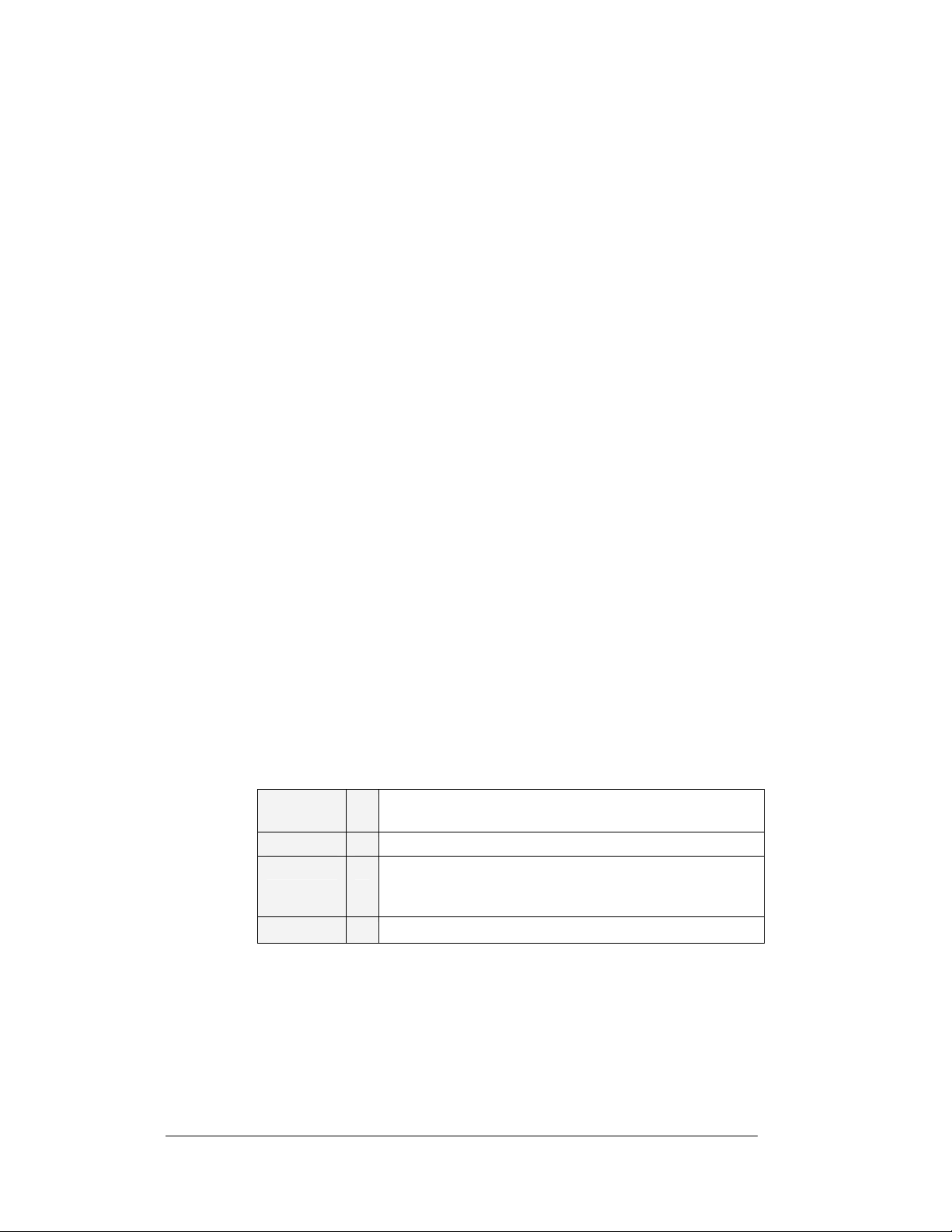
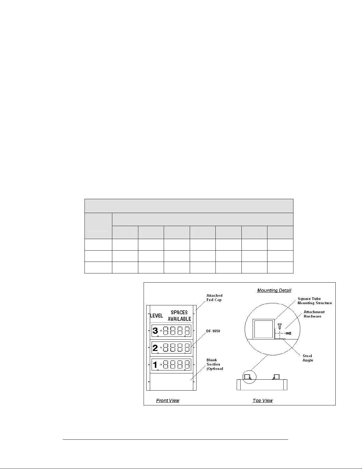
There are two basic models in the numeric, or fixed-digit, parking display series: DF1050 and DF-1051. Figure 2 and Figure 3 shows that both are modular displays, but
DF-1050 signs are typically used in a tower arrangement with end caps, while DF1051 signs have a drop-in cabinet, designed for placement in an existing parking
garage structure, in a wall cutout or in a new custom sign.
1-4 Introduction
Page 11
Figure 2: Model DF-1050
Because this series is based on a modular design, there can be any number of module
and caption combinations. Some displays may utilize a single module, while others
may consist of multiple modules arranged vertically. Each model has four digits that
can display the words “OPEN” and “FULL” as well as any number from 0 to 9999.
The text messages or numbers are controlled via signal protocol.
Caption modules are un-powered units that attach to the top or bottom of a digit
module. Caption modules all use permanent vinyl lettering. Some signs may also use
optional “blank” modules as filler or spacer panels.
Each section in this manual contains model-specific information, including physical
dimensions, digit configuration and power requirements. Display drawings, located
in Appendix A, also list dimensions, weight and mounting instructions for each
display. Additionally, model number and electrical requirements can be found on a
label located on the display's entrance panel.
The Parking Garage displays have been designe d for use with the Daktronics
DataMaster
Daktronics DataMaster parking garage so ftware and the appropriate interface. Refer
to Section 5 for detailed operating information.
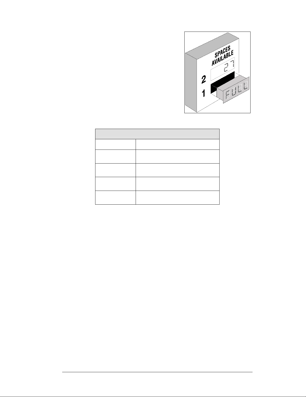
Figure 3: Model DF-1051
™
100 hand-held console. Other controllers may be used to control
1.4 Component Identification
The following terms include some of the more commonly used terms when referring
to these displays. Because Daktronics occasionally alters standard design to meet
customer needs, the actual display design may vary slightly from the illustrations
below.
This is only a brief overview. Refer to Section 4 for additional information on
maintaining the various display components.
Introduction 1-5
Page 12

Client: The client display contains a client driver that receives signal from the “host”
driver on the Signal IN terminals. These drivers can re-drive signal to other client
drivers.
DataMaster Controller (DM100): The handheld keyboard like device used to set
the time, date, hold times, dimming etc. on the Parking Garage display. See Section
5 for more information on the DataMaster controller.
Display Address: The display address is an identification number assigned to each
driver in a network. The address is set using an 8-position binary switch on the driver
board. For single-line displays, the address will typically be “1”. For Parking Garage
displays with several levels, the top display is often set to address “1” and the others
are set to “2”, “3” etc. The address will be displayed each time the display powers
up.
Digit Circuit Board: The LEDs are mounted to a circuit board, which mounts to the
back of a digit panel. Problems with individual digits, segments or LEDs may require
accessing or replacing this board.
Host/Primary: The host display contains the host driver which relays signal directly
from the DataMaster controller on its Signal IN terminals. It is the only driver
connected to the temperature/photo sensor. The Signal OUT terminals are used to
connect the client driver. The host driver is selected by inserting the “Protocol-4”
plug into the protocol jack.
LED (light emitting diode): LEDs are high-intensity, low-energy lighting units.
Mirror/slave: receives a signal from the master but does not have a driver.
Power Supply: Converts AC line voltage from the load center to low DC voltage for
one or more digit circuit boards.
Protocol plug: The “Protocol-4” plug is inserted in the 5-pin protocol jack to select
the host driver for a set of host-client displays.
1.5 Daktronics Nomenclature
To fully understand some Daktronics drawings, such as schematics, it is necessary to
know how various components are labeled in those drawings. You will find this
information useful when trying to communicate maintenance or troubleshooting
efforts.
The following labeling formats might be fou nd on va ri o us Daktronics drawings:
• “TB _ _” denotes a termination block for power or signal cable.
• “E _ _” denotes a grounding point.
• “J _ _” denotes a power or signal jack.
• “P _ _” denotes a power or signal plug for the opposite jack.
Finally, Daktronics part numbers are commonly found on drawings. Those part
numbers can be used when requesting replacement parts from Daktronics Customer
1-6 Introduction
Page 13

Service. Take note of the following part number formats. (Not all possible formats
are listed here.)
• “0P- _ _ _ _- _ _ _ _” denotes an individual circuit board , such as a drive r
board.
• “0A-_ _ _ _ - _ _ _ _” denotes an assembly, such as a circuit board and the
plate or bracket to which it is mounted. A collection of circuit boards
working as a single unit may also carry an assembly label.
• “W- _ _ _ _ ” denotes a wire or cable. Cables may also carry the assembly
numbering format in certain circumstances. This is especially true for
ribbon cables.
Most circuit boards and components within this display carry a label that lists the
part number of the unit. If a circuit board or assembly is not listed in the
Replacement Parts List in Section 4.5, use the label to order a replacement. A
typical label is shown in
Figure 4. The part number is in bold.
Figure 4: Typical Label
Introduction 1-7
Page 14

Page 15
Section 2: Mechanical Installation
Note: Daktronics does not guarantee the warranty in situations where the display is
not constantly in a stable environment.
Daktronics engineering staff must approve any changes that may affect the weathertightness of the display. If any modifications are made, detailed drawings of the
changes must be submitted to Daktronics for evaluation and approval, or the
warranty may be void.
Daktronics is not responsible for installations of structural integrity of support
structures done by others. It is the customer’s responsibility to ensure that a
qualified structural engineer approves the structure and any additional hardware.
2.1 Mechanical Installation Overview
Mechanical installation consists of attaching end caps, mounting the display to
support columns or mounting the units in parking facility walls or into existing
signage.
The table below shows all of the weights and dimensions for each model in this
series. Models are listed in order by digit size.
Model
DF-1050
DF-1050
DF-1050
DF-1051
DF-1051
DF-1051
Digit
Height/Color
5" (127 mm)
Red or amber
7" (178 mm)
Red or amber
10" (254 mm)
Red or amber
5" (127 mm)
Red or amber
7" (178 mm)
Red or amber
10" (254 mm)
Red or amber
Dimensions
(Height, Width, Depth)
H10", W28", D6.2"
(254 mm, 711 mm, 157 mm)
H12", W40", D6.2"
(305 mm, 1016 mm, 157 mm
H15", W52", D6.2"
(381 mm, 1321 mm, 157 mm)
H8", W18", D5.56"
(203 mm, 711 mm, 141 mm)
H12", W27", D5.75"
(305 mm, 711 mm, 146 mm)
H15", W36", D5.75"
(381 mm, 711 mm, 146 mm)
Approximate Weight
(per Section)
14 lb
(6.4 kg)
20 lb
(9.1 kg)
32 lb
(14.5 kg)
6 lb
(2.7 kg)
14 lb
(6.4 kg)
23 lb
(10.4 kg)
DF-1051
13" (330 mm)
Red or amber
H19", W50", D5.75"
(483 mm, 711 mm, 146 mm)
43 lb
(19.5 kg)
Mechanical Installation 2-1
Page 16
2.2 Mechanical Installation
Reference Drawings:
Mechanical Spec, DF-1050......................................... Drawing A-191157
Mechanical Specification Drawings..........................Refer to Appendix A
As noted previously, the DataMaster Parking Garage displays are designed for either
tower or flush wall mounting. Refer to the Mechanical Specifications Drawings for
installation details.
DF-1050 Installation
DF-1050 modules are assembled with end caps and attached with angles to a support
structure provided by the customer. Refer to Drawi ng A-191157 for detailed
mounting information. Individual drawings for each DF-1050 model are listed in
Appendix A.
End caps are manufactured to have an appropriate height based on the number of
sections or modules the finished display has. The following table provides a guide
for vertical display heights:
DF-1050Display Heights
Overall Height According to Number of Sections Digit
Size
5" 40" 50" 60" 70" 80" 90" 100"
7" 48" 60" 72" 84" 96" 108" –
10" 60" 75" 90" 105" – – –
4 5 6 7 8 9 10
Figure 5 illustrates a
typical DF-1050
installation. Note that
the individual
cabinets attach to the
end caps with a single
screw on either side
of the display (front
and back surfaces).
Holes for the end caps
and for the steel
mounting angles are
pre-drilled, and
hardware for those
components is
provided by
Daktronics.
Figure 5: DF-1050 Mounting
2-2 Mechanical Installation
Page 17
DF-1051 Installation
DF-1051displays are “drop in” models, intended
for flush wall mounting or placem e nt in a cuto ut
of an existing sign. (The cabinet is complete with
a front flange or bezel that provides a finished
border for flush wall or in-sign applications.)
The drop-in feature is illustrated in Figure 6.
The size of the sign or wall cutout varies,
depending on the model, as shown in the
following table:
Figure 6: DF-1051 Drop-In
DF-1051 Series: Cutout Needed for Mounting
Model Cutout Dimensions
DF-1051-5
DF-1051-7
DF-1051-10
DF-1051-13
H6.25", W16.25", D5.56"
(159 mm, 419 mm, 141 mm)
H9.5", W25", D5.75"
(241 mm, 635 mm, 146 mm)
H12.5", W34", D5.75"
(318 mm, 864 mm, 146 mm)
H16.38", W47.75", D5.75"
(416 mm, 1213 mm, 146 mm)
Prior to mounting, run conduit to the display location and make all power and signal
wiring connections. With the electrical hookup completed, simply slide the display
into the wall cutout and secure it at the mounting holes across the top, sides and
bottom. Be sure to use anchors and other mounting hardware appropriate for the wall
material.
The Mechanical Specification Drawings give details on the cutouts needed and the
location of the mounting holes.
Mechanical Installation 2-3
Page 18

Page 19

Section 3: Electrical Installation
Daktronics Parking Garage displays are ETL listed and tested to CSA standards.
Contact Daktronics with any questions regarding the testing procedures.
Only qualified individuals should perform power routing and termination to the
display. It is the responsibility of the electrical contractor to ensure that all
electrical work meets or exceeds local and national codes.
3.1 Preparing for Power/Signal Connections
Reference Drawings:
Enclosed Driver, 4-col MASC, Wide............................Drawing A-191943
Electrical Specification Drawings............................. Refer to Appendix A
Electrical installation consists of the following processes:
• Providing power and ground to a disconnect near the display.
• Routing power and ground from the main disconnect to the display driver
enclosure.
• Connecting the ground to a grounding electrode at the display location.
• Routing the control signal cable from the control location to the display
location.
Electrical Specifications Drawings for displays in this series show the locations of
internal components and display signal and electrical access holes. Refer to these
drawings before making power and signal connections. All power and signal
terminates to blocks within the driver enclosure, immediately below the power
supply. Termination is to be completed by the customer's electrician to the power
terminal block (TB4). Refer to Drawing A- 19 1943.
3.2 Power and Grounding Connections
Correct power and grounding installation is imperative for proper display operation.
The subsections that follow give details of display power and installation. Only
qualified individuals should attempt to complete the electrical installation. Improper
installation could result in serious damage to the equipment and could be hazardous
to personnel.
Power
Daktronics DataMaster displays have been designed for easy access to components,
and to power and control signal hookup. Front panels ar e hinged to allow access to
the digits, cabling and other electronic components.
The DataMaster, Parking Garage displays require a dedicated, 120 VAC circuit for
incoming power. The display itself has no breakers or fuses.
Power conductors and conduit are to be sized and installed by the customer's
electrician. Knockout-type access holes for the conduit are
both sides of the display.
Electrical Installation 3-1
7
/8" and located on the
Page 20
The table below shows the circuit specifications and maximum power requirements
for each model in this series. Models are listed in order by digit size, and display
type.
Model
Digit
Height/Color
Maximum
Wattage
Power
Amps
per Line
DF-1050
DF-1050
DF-1050
DF-1051
DF-1051
DF-1051
DF-1051
5" (127 mm)
Red or amber
7" (178 mm)
Red or amber
10" (254 mm)
Red or amber
5" (127 mm)
Red or amber
7" (178 mm)
Red or amber
10" (254 mm)
Red or amber
13" (330 mm)
Red or amber
30 W 120 V
AC
150 W 120 V
AC
150 W 120 V
AC
30 W 120 V
AC
150 W 120 V
AC
150 W 120 V
AC
150 W 120 V
AC
0.3A
1.3 A
1.3 A
0.3 A
1.3 A
1.3 A
1.3 A
Grounding
Reference Drawings:
Enclosed Driver, 4 Col MASC, Wide........................... Drawing A-191943
Displays MUST be grounded according to the provisions outlined in Article 250 of
the National Electrical Code and according to the specifications in this manual.
Daktronics requires a resistance-to-ground of 10 ohms or less.
The contractor performing the electrical installation can verify ground resistance.
Technicians from Daktronics Sales and Service offices can also provide this service.
The display system must be connected to an earth electrode installed at the display.
Proper grounding is necessary for reliable equipment operation. It also protects the
equipment from damaging electrical disturbances and lightning. The display must be
properly grounded, or the warranty will be void. Refer to Drawing A-191943, for
information on where to connect the grounding wire. Connection at the driver
enclosure terminal block is illustrated at the bottom of the drawing.
The material for an earth-ground electrode differs from region to region and may
vary according to conditions present at the site. Consult the National Electrical Code
and any local electrical codes that may apply. The support structure of the display
cannot be used as an earth-ground electrode. The support is generally embedded in
concrete, and if it is in earth, the steel is usually primed or it corrodes, making it a
poor ground in either case.
3-2 Electrical Installation
Page 21

Power Installation
There are two considerations for power installation: installation with ground and
neutral conductors provided, and installation with only a neutral conductor provided.
These two power installations differ slightly, as described in the following
paragraphs:
Installation with Ground and Neutral Conductors Provided
For this type of installation, the power circuit must contain an isolated earth-ground
conductor. Under this circumstance, do not connect neutral to ground at the
disconnect or at the display. This would violate electrical codes and void the
warranty. Use a disconnect so that all hot lines and neutrals can be disconnected. The
National Electrical Code requires the use of a lockable power disconnect within sight
of or at the display.
Installation with Only a Neutral Conductor Provided
Installations where no grounding conductor is provided must comply with Article
250-32 of the National Electrical Code. If the installation in question meets all of the
requirements of Article 250-32, the following guidelines must be observed:
• Connect the grounding electrode cable at the local disconnect, never at the
display driver/power enclosur e.
• Use a disconnect that opens all of the ungrounded phase conductors.
3.3 Lightning Protection
The use of a disconnect near the display to completely cut all current-carrying lines
significantly protects the circuits against lightning damage. The National Electrical
Code also requires it. In order for this device to provide protection, the power must
be disconnected when the display is not in use. The control console should also be
disconnected from power and from the signal j-box when the system is not being
used. The same surges that may damage the display's driver can also damage the
driver console's circuit.
3.4 Signal Connection
Reference Drawing:
Enclosure Driver, 4 Col MASC, Wide ..........................Drawing A-191943
Electrical Specification Drawings............................. Refer to Appendix A
To gain access to the driver enclosure, open the access door and remove the cover
from the enclosure. Refer to the Electrical Specification Drawings for the access
location for your sign.
Route power and signal cables into either side of the display, where there is a
separate knockout for signal conduit. The signal cable terminates to the signal
terminal block (TB3) in the driver enclosure, immediately below the power supply
and to the right of the power connectors. The component is a dual-row barrier
terminal block, and it accommodates “Signal In,” “Signal Out,” and “12 V DC Out”
as well as “Inc” (increment), “Dec” (decrement), “Open,” “Full” and “Common”
terminals for operating the display from switches.
Electrical Installation 3-3
Page 22
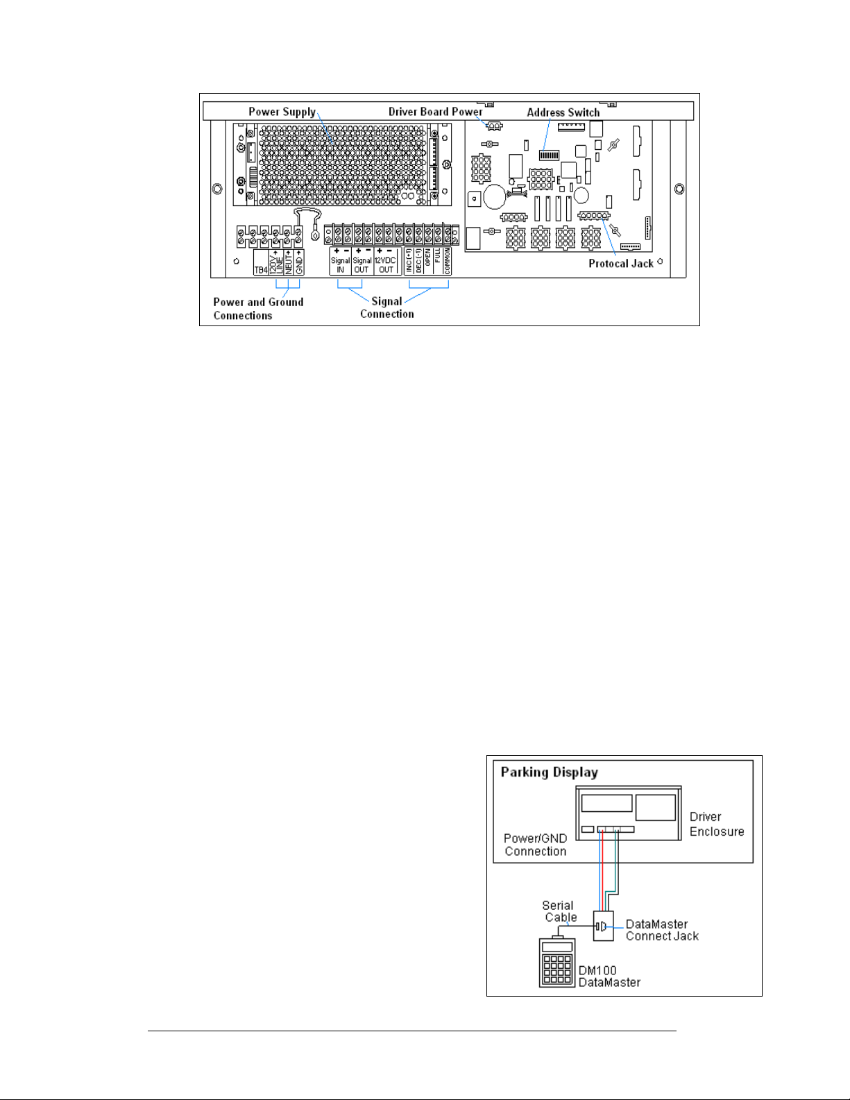
Figure 7: DataMaster Driver Enclosure with 4-Column Driver
The customer's electrician completes the signal termination as shown on the
schematic, Drawing A-191943. Recommended signal conductor is 2-pa ir, 22 AWG,
stranded with shield (Daktronics part number W-1234), but 18 AWG may b e us ed as
indicated on the drawing. If the sign is to be operated from switches, this wiring may
be done using 22 AWG cable. Shielded cable is recommended if the switch wiring is
run next to other cables that may induce noise in the switch wiring.
Daktronics provides the protocol plug for the signal, and the customer may use
standard DataMaster software or may provide his or her own software.
Current Loop (DataMaster)
Reference Drawing:
Enclosure Driver, 4 Col MASC, Wide.......................... Drawing A-191943
A directly controlled display uses a current loop connection from the j-box at the
display to the driver enclosure in the sign. All the power and signal wiring terminates
at the driver enclosure. The DataMaster hand-held controller receives its power from
the display. The display layout is shown in Figure 8.
Note: The cable from the j-box to the display needs to be routed through conduit or
the display pole to protect it from weather or vandalism.
1. Mount the j-box near the display.
2. Route a 4-conductor cable through conduit
from the j-box to the driver enclosure in the
host display. (Distance limit from the j-box
to the display is 50 ft.)
3. Connect the signal/power cable from the j-
box to the driver enclosure as shown in
Figure 9 and listed in the table. Refer to
Drawing A-191943 for additional
information.
4. Using a DB9M to DB9F serial cable, plug
the DataMaster controller into the j-box
connected to the driver enclosure.
Figure 8: Direct, DataMaster Control
3-4 Electrical Installation
Page 23

Figure 9: DataMaster Connections
DataMaster Signal Connections
J-Box
Pin#
Pin 1 Red 12V DC Out (+) pin 7
Pin 2 Black 12 V DC Out (-) Pin 8
Pin 5 White Signal IN (-) Pin 2
Pin 6 Green Signal IN (+) Pin 1
Cable
Color
Enclosure Terminal
Block
A typical control setup for parking garages will be one in which the signs are
controlled remotely from a booth or office in the facility. Signal cabling is similar to
wired, base-of-sign control, except that the controller requires a wall pack
transformer. The transformer plugs into both the hand-held controller and into a
120VAC outlet. The DataMaster controller also connects to a junction box to send
signal to the display, but the j-box will be located within the booth or office. The
operator then changes the display by entering current parking information and
operating instructions on the keypad of the DataMaster controller. For complete
details on sign operation, refer to Section 5.
Current Loop (Signal Converter)
Reference Drawing:
Enclosure Driver, 4 Col MASC, Wide ..........................Drawing A-191943
System Riser Diagram; DF Display, Parking Lot.........Drawing A-196787
A display, or set of displays, can be progra mmed using a current loop signal from a
signal converter. The signal into the display can be sent directly from the computer,
through the signal converter, and then into the display, or the signal can be extended
through the use of two signal converters. The following sections will explain the two
different communication methods.
Electrical Installation 3-5
Page 24

Standard Wire Current Loop Setup
A standard wire connection requires a computer connected to a signal converter, and
then signal cable connected to the display. Refer to Figure 10 and Draw i ng A-
196787 for system layout.
Figure 10: Standard Wire (Current Loop) Layout
1. Using a DB9M to DB9F serial cable (W-1267) connect from the computer
to J1 on the signal converter (0A-1065-0173).
2. Using a two -conductor, 22AWG, shielded cable (W-1077) to connect from
TB1 on the signal converter to the terminal block in the display. The
maximum distance is 1000 feet.
3. Connect from pin 1 of TB1 of the signal converter to pin 1 of the terminal
block in the display, and pin 2 to pin 2.
4. Refer to Figure 11 and Drawing A-191943 for the display connections.
Figure 11: Standard Wire Signal Connections
3-6 Electrical Installation
Page 25

Standard Fiber Optic Setup
A standard fiber optic connection requires a computer connected to a signal
converter, a fiber optic cable connected to a second signal converter, and then signal
cable connected to the display. Refer to Figure 12 and Drawing A-196787 for
system layout.
Figure 12: Standard Fiber Optic Layout
1. Using a DB9M to DB9F serial cable (W-1267) connect from the computer
to J1 on the fiber optic signal converter (0A-1065-1074).
2. Connect from J5 (TX) on the first signal converter to J4 (RX) on the second
signal converter. The maximum distance is 4000 ft.
3. Using a two-conductor, 22 AWG, shielded cable (W-1077) to connect from
TB1 on the signal converter to the terminal block in the display. The
maximum distance is 1000 ft.
4. Conn ect from pin 1 of TB1 of the second fiber optic signal converter to pin
1 of the terminal block in the display, and pin 2 to pin 2.
5. Refer to Figure 13 and Drawing A- 191943 for the display connections.
Figure 13: Stand Fiber Optic Signal Connections
Electrical Installation 3-7
Page 26

Manual Control Functions
Reference Drawing:
Enclosure Driver, 4 Col MASC, Wide.......................... Drawing A-191943
System Riser Diagram; DF Display, Parking Lot ........ Drawing A-196787
This is the simplest control
scheme, suitable for low cost
applications where an integrated,
remote control system is not
needed. Using the switches, a
four-digit display can be made to
count from 0 to 9999, blank, or
display ‘OPEN’, or ‘FULL’.
Data sent to the display from
third party software, or from the
DM-100 controller will override
the switch inputs. When the data
signal is removed, the display
will be blank until a switch
closure is sensed.
The signal will be sent using three wires from the switch box to the display. Refer to
Figure 14 and Drawing A-196787 for system layout.
1. The switch box has three pre-attached wires that will need to be connected
to the wires going to the display using wire nuts.
2. Using a 2-pair, 22AWG, cable, connect to the wires going to the display.
The maximum distance is 1000 feet.
3. Use the table and figures to connect the manual switch box to the display.
(Note: The switch box can control the display to either increment o r
decrement a number or to switch between open and full.)
As shown on Drawing A-19 19 4 3,
the terminal block inside the driver
provides connections for 4
switches: INC. (+1), DEC. (-1),
‘OPEN’ and ‘FULL’. Switch
control is implemented by wiring
from these terminals to normally
open switches, as shown on
Drawing A-196787. An optional
switch assembly containing
momentary toggle switches in an
outdoor enclosure is available from
Daktronics (0A-1279-0403).
3-8 Electrical Installation
Figure 14: Manual Control Layout
Figure 15: Manual Control Connections
Page 27

INC. (+1): Closing this switch momentarily increments the count by 1. Holding
the switch closed will cause the display to increment rapidly. If the
count is at ‘9999’, incrementing will cause the display to blank.
Incrementing again will roll the count over to ‘0’.
DEC. (-1): Closing this switch momentarily decrements the count by 1. Holding
the switch closed will cause the display to decrement rapidly. If the
count is at ‘0’, decrementing will cause the display to blank.
Decrementing again will roll the count over to ‘9999’
OPEN: Closing this switch momentarily makes the display show ‘OPEN’. A
toggle switch may be connected to this input to hold it closed if it is
desired to have the display revert to ‘OPEN’ whenever the data signal
is not present.
FULL: Closing this switch momentarily makes the display show ‘FULL’. A
toggle switch may be connected to this input to hold it closed if it is
desired to have the display revert to ‘FULL’ whenever the data signal is
not present.
To Quickly Reset the Count to ‘0’:
Hold the INC. and DEC. switches closed at the same time until the count resets.
To Blank the Display:
Reset the count to ‘0’ and then decrement once.
Connecting Client Displays:
The display controller will transmit its display information on the “Signal Out”
terminals available inside the control enclosure. Any display, set to the same address
as the sending display, can receive this signal and show the exact same information.
3.5 Host/Client and Address Settings
Reference Drawing:
4 Column MASC LED Driver Specification..........................Drawing A-166216
Enclosed Driver, 4-col MASC, Wide.....................................Drawing A-191943
Address settings, MASC drivers.............................................Drawing A-227502
Host/Client Definitions
One driver at each sign installation is designated as the “host driver.” This driver
receives its signal from the DM100 controller or signal converter. The “Signal OUT”
terminals are used to connect to “client drivers.” Refer to Drawing A-191943 and
Figure 16: Host, Signal Out to Client, Signal In
Electrical Installation 3-9
Page 28

Figure 16 for an illustration of the host/client display connection.
Select the host driver by inserting the Protocol 4 plug into the 5-pin protocol jack
(J20.) For protocol jack location, refer to Drawings A-166216.
All other drivers in the display system are client drivers. These drivers receive signal
from the host driver on the Signal IN terminals and can re-drive this signal to other
“client drivers” on the Signal OUT terminals.
The address is an identification number assigned to each sign or display in a
network. Drawing A-227502 shows how to set the address on the drivers used in the
DataMaster and DataTime products. The control software uses the address to locate
and communicate with each sign. Because of the variety of installations using
DataMaster displays, addressing for each unit will be determined at point of sale or
installation. In general, a typical Level 1 parki ng
display would have an address of 1, a Level 2
would have an address of 2, and so on.
The address of each driver is set using an 8position DIP-switch (S1), and the address is
based on that driver’s position in the sign or
display system. If a single-line sign is used, the
address will typically be Address “01.” This
means that switch 1 is turned “ON” and the
remaining 7 switches are in the “OFF” position.
This is the default address, set when each display
is shipped. In multiple-product displays, the
address determines which line of information is
shown on the driver’s digits. The switch is set
using a binary address. Use the table and the
examples for setting the address.
Figure 17: Common Address
Settings
Binary Address Settings
Address 1 2 3 4 5 6 7 8
1 ON OFF OFF OFF OFF OFF OFF OFF
2 OFF ON OFF OFF OFF OFF OFF OFF
3 ON ON OFF OFF OFF OFF OFF OFF
4 OFF OFF ON OFF OFF OFF OFF OFF
5 ON OFF ON OFF OFF OFF OFF OFF
6 OFF ON ON OFF OFF OFF OFF OFF
7 ON ON ON OFF OFF OFF OFF OFF
8 OFF OFF OFF ON OFF OFF OFF OFF
9 ON OFF OFF ON OFF OFF OFF OFF
10 OFF ON OFF ON OFF OFF OFF OFF
11 ON ON OFF ON OFF OFF OFF OFF
12 OFF OFF ON ON OFF OFF OFF OFF
13 ON OFF ON ON OFF OFF OFF OFF
14 OFF ON ON ON OFF OFF OFF OFF
15 ON ON ON ON OFF OFF OFF OFF
Note: Some older drivers set the address of each driver using an address plug
(Daktronics part # 0A-1279-0122) in J19. The address, either using a switch or a
plug, needs to be set for each driver.
3-10 Electrical Installation
Page 29

Section 4: Maintenance and
Troubleshooting
IMPORTANT NOTES:
1. Disconnect power before doing any repair or
maintenance work on the display.
2. Permit only qualified service personnel to access
internal display electronics.
3. Disconnect power when the display is not in use.
4.1 Cabinet Specifications
Reference Drawings:
Mechanical Specification Drawings .........................Refer to Appendix A
Cabinets for the Daktronics outdoor LED digit displays are constructed of heavy
gauge aluminum. Exact dimensions and weights for each model are listed in the
chart in Section 2. The Mechanical Specification Dr aw i n gs and the following
sections detail the access and location to the displays interior components.
4.2 Component Location and Access
Reference Drawing:
Electrical Specification Drawings............................. Refer to Appendix A
Mechanical Specification Drawings .........................Refer to Appendix A
Displays in the DataMaster Parking Garage display series are made up of two main
components: the circuit boards that make up the digits and the driver enclosure.
Display digits are made up of a single circuit board that is mounted to the face plate
of the display.
Each host display contains an enclosure that includes the following parts:
• Display driver
• 24V DC power supply
• Signal/power input terminal locks
The DataMaster Parking Garage displays are front-access, meaning that the displays
open from the front for all service. The face panel is held to the display by a variable
number of screws depending on the display size and type. Removing the faceplate
will allow access to all the internal components. Refer to the Mechanical
Specification Drawings for locations and numbers of screws in the panel.
Maintenance and
Troubleshooting
4-1
Page 30

1. The drop-in cabinet style displays have screws holding the faceplate in
place. The other cabinets have screws along the bottom and the faceplate
will then slide down and out when they are removed.
2. Remove the No. 10 screws (four or six, depending on the model) securing
the digit face panel to the display cabinet.
3. Carefully pull the face panel out of the display.
4. Unplug the 9-pin connectors on the rear of the digits by squeezing the two
tabs together and carefully pulling the connector from the digit.
Figure 18: Parking Garage Display
4.3 Service and Diagnostics
Digit Replacement
The digit circuit board, the platform for the LEDs is mounted to the back of the face
panel. Do not attempt to remove individual LEDs. In the case of a malfunctioning
board, replace the entire digit panel. Refer to Figure 19 for the digit assembly.
To remove and replace a digit, follow these steps.
1. Follow th e steps in Section 4.2 to gain access to
the digits.
2. Unplug the connector on the back of the digit.
3. Unscrew th e four nuts, securing the failed digit
to the panel.
4. Lift the digit off of the panel. (Take note of the
digit orientation.)
5. Replace the digit with a new one. Secure the
replacement with the nuts you removed from the
failed digit. Note that standoffs, or spacers, are
used between the front of the digit and the face
panel, but the LEDs must protrude through holes
in the face panel.
6. Plug the 9-pin connector into the rear of the
digit. These are keyed connectors, which means
they will only fit one way. Do not force the
connection!
7. Replace the digit panel by securing it with the
No.10 screws.
Figure 19: Digit Replacement
4-2
Maintenance and
Troubleshooting
Page 31

Segmentation and Digit Designation
Reference Drawings:
Segmentation, 7 Segment Bar Digit...............................Drawing A-38532
Electrical Specification Drawings............................. Refer to Appendix A
In each digit, certain LEDs always go on and off together. These groupings of LEDs
are referred to as segments. Drawing A-38532 illustrates digit segmentation and
details which connector pin is wired to each digit segment along with the wiring
color code used throughout the display.
The Electrical Specifications
Drawings for each model specify
the driver connectors controlling
the digits. Numbers shown in
hexagons in the upper half of each
digit, as illustrated in Figure 20,
indicate which connector is wired
to that digit.
Figure 20: Digit Designation
LED Driver
Reference Drawings:
4 Column MASC LED Driver Specifications................Drawing A-166216
Enclosed Driver, 4-Col MASC, Wide ...........................Drawing A-191943
Electrical Specification Drawings............................. Refer to Appendix A
Mechanical Specification Drawings .........................Refer to Appendix A
Drivers are typically mounted inside the display enclosure and behind the digit face
panel. Refer to the Electrical and Mechanical Specification Drawings for the
location of your driver enclosure. In each driver enclosur e there is an LED driver, a
power supply, and termination blocks. Drawing A-191943 illustrates the complete
driver enclosure.
To replace the driver in the display enclosure:
1. Follow th e steps in Section 4.2 to gain access to the driver enclosure.
2. Refer to Drawing A-191943 and remove the enclosure cover by loosening
the two side screws and then sliding the cover up to the larger part of the
keyhole opening. Lift the cover off the enclosure.
3. It is helpful to have the cable labeled, noting which was removed from
which connector.
4. Disconnect all connectors from the driver. Release each connector by
squeezing together the locking tabs as you pull the connector free. Note:
When reconnecting, remember that these are keyed connectors and will
attach in one way only. Do not attempt to force the connections.
5. Remove the wing nuts, securing the driver to the inside of the enclosure.
6. Carefully lift the driver from the display and place it on a clean, flat surface.
7. Follow th e steps in reverse order to attach a new driver
In the display, the LED driver performs the task of switching digits on and off.
Refer to Drawing A-166216 and Figure 21 for the major functions of a 4-column
driver.
Maintenance and
Troubleshooting
4-3
Page 32

Figure 21: 4-Column Digit Driver
The following table lists the functions of the various jacks, including those that are
not used in this application.
Driver LED Driver Jack Functions
Jack No. Function
J1-J4 (4-column)
Digits Output
J18, J21, J22, J25, J26, J27,
J17
J20
J23
J24
TB1
J19
J28
Signal/Power Input
Protocol-5 Location
12 VDC Power Out
Modem
CAN (photo sensor)
Address Plug (older drivers only)
Jacks not used in this application
The display address is set with a DIP-switch on the display driver at Daktronics
before shipment. (Note: Some older drivers use a 12-pin address plug inserted in
J19). All DataMaster displays ship with the “Line 1” address already set.
4-4
Maintenance and
Troubleshooting
Page 33

Light Sensor Installation
Reference Drawings:
Light Sensor Installation, G3........................................Drawing A-183775
System Riser; Light Sensor .........................................Drawing A-210516
Mechanical Specification Drawings .........................Refer to Appendix A
Displays in the DataMaster series use a light sensor to regulate sign dimming
functions. Use Drawing A-1837 7 5 and the following instructions to replace the light
sensor in your DataMaster Parking Garage display.
If the sign or sign system has more than one display and is being controlled by the
DM-100 controller or using software based on the Daktronics Venus 1500 protocol,
install the light sensor in the host display only. If the system is controlled by
software based on the Daktronics multi-drop protocol, refer to Drawing A-210516
for wiring options.
1. Open the display as described in
Section 4.2. The light sensor will
usually be mounted to the panel
between the first and second digits.
2. Locate and remove the
from front panel of the display, as
shown in Figure 22.
3. Ther e are two 6-32 studs above and
below the plughole. The internal light
sensor assembly (Daktronics part #0A1279-0203) is positioned on the studs,
with the clear lens toward the front of
the cabinet and the cable at the bottom.
Secure the sensor with the plastic wing
nuts provided with the assembly kit.
4. Route the signal cable to the driver and
insert the 6-position plug into the
mating jack (TB1) on the driver.
5. Close the display face panel.
5
/8" plastic plug
Figure 22: Light Sensor
Installation
4.4 Troubleshooting
This section lists some symptoms that may be encountered with the display. For
these symptoms, possible cause and corrective actions are indicated. This list does
not include every possible problem, but does represent some of the more common
situations that may occur.
Symptom/Condition Possible Cause or Corrective Action
Entire display fails to work • Check for proper line voltage at termination
Cannot communicate with display via
current loop
Maintenance and
Troubleshooting
panel
• Check connections from power supply to
driver (J17)
• Check power LED on driver
• Check connections at J-box and display
• Make sure DataMaster is receiving power
• Check serial cable from DataMaster to j-
box
4-5
Page 34

Cannot communicate with display
using the signal converter
Garbled display. • Control console malfunction
Digit will not light. • Black wire to the digit is broken
Segment will not light. • Driver malfunction
Segment stays lit. • Driver malfunction
Data appears in the wrong place on
the display/ Wrong data on a particular
line of the display
4.5 Replacement Parts
To prevent loss due to theft, Daktronics recommends purchasing a lockable cabinet
to store manuals and replacement/spare parts.
Following is a list of parts used in the Daktronics parking displays:
Description
Driver, 4-col MASC LED, DC 0P-1192-0068
• Check power to the signal converter and
display
• Check connections between sign al
converter and display
• Check serial cable from computer to signal
converter
• Check use of the software
• Internal LED driver malfunction
• Poor contact at driver connector
• Driver malfunction
• Broken wire between LED driver and digit
• Poor contact at driver connector
• Short circuit on the digit
• Incorrect address on drivers (consult table
to set correct address)
• Incorrect wiring between displays
Daktronics Part
Number
Power supply, 24 V, 150 W A-1720
Power supply, 12 V, 30 W A-1498
Signal Converter, 120V, CL output 0A-1065-0173
Signal Converter, 120V, CL out, w/Fiber 0A-10 65-0174
Switch box, outdoor rated 0A-1279-0403
Light Sensor assembly 0A-1279-0203
Digit, 5" red LED, 7-seg, G3, 12V 0P-1192-0263
Digit, 5" amber LED, 7-seg, G3, 12V 0P-1192-0264
Digit, 7" red LED, 7-seg, G3 0P-1192-0242
Digit, 7" amber LED, 7-seg, G3 0P-1192-0243
Digit, 10" red LED, 7-seg, G3 (Model DF-1050) 0P-1192-0251
Digit, 10" amber LED, 7-seg, G3 (Model DF-1050) 0P-1192-0252
Digit, 10" red LED, 7-seg, 2 row, 24 V, G3
(Model DF-1051-10)
4-6
Maintenance and
0P-1192-0255
Troubleshooting
Page 35

Digit, 10" amber LED, 7-seg, 2 row, 24 V, G3
(Model DF-1051-10)
Digit, 13" (15") red LED, 7-seg, G3 0P-1192-0200
Digit, 13" (15") amber LED, 7-seg, G3 0P-1192-0214
Address plug 0A-1150-0064
0P-1192-0256
4.6 Daktronics Exchange and Repair and Return
Programs
To serve customers' repair and maintenance needs, Daktronics offers both an
Exchange Program and a Repair and Return Program.
Daktronics' unique Exchange Program is a quick, economical service for replacing
key components in need of repair. If a component fails, Daktronics sends the
customer a replacement, and the customer, in turn, sends the failed component to
Daktronics. This not only saves money but also decreases display downtime. The
company offers the service to qualified customers who follow the program
guidelines explained below.
Daktronics provides these plans to ensure users get the most from their Daktronics
products. Please call the Help Desk – (877) 605-1113 – if you have questions
regarding the Exchange Program or any other Daktronics service.
When you call the Daktronics Help Desk, a trained service technician will work with
you to solve the equipment problem. You will work together to diagnose the problem
and determine which exchange replacement part to ship. If, after you make the
exchange, the equipment still causes problems, please contact the Help Desk
immediately.
If the replacement part fixes the problem, package the defective part in the same box
and wrapping in which the replacement part arrived, fill out and attach the enclosed
UPS shipping document, and RETURN THE PART TO DAKTRONICS. In most
circumstances, you will be invoiced for the replacement part at the time it is shipped.
This bill is due when you receive it.
Daktronics expects immediate return of an exchange part if it does not solve the
problem. The company also reserves the right to refuse equipment that has been
damaged due to acts of nature or causes other than normal wear and tear.
If the defective equipment is not shipped to Daktronics within 30 working days from
the invoice date, it is assumed you are purchasing the replacement part, and you will
be invoiced for it. This second invoice represents the difference between the
exchange price and the full purchase price of the equipment. The balance is due
when you receive the second invoice. If you return the exchange equipment after 30
working days from the invoice date, you will be credited for the amount on the
second invoice, minus a restocking fee.
To avoid a restocking charge, please return the defective equipment within 30
days from the invoice date.
Maintenance and
Troubleshooting
4-7
Page 36

Daktronics also offers a Repair and Return program for items not subject to
exchange.
Return Materials Authorization: To return parts for service, contact your local
representative prior to shipment to acquire a Return Material Authorization (RMA)
number. If you have no local representative, call the Daktronics Help Desk for the
RMA. This expedites repair of your component when it arrives at Daktronics.
Packaging for Return: Package and pad the item well so that it will not be damaged
in shipment. Electronic components such as printed circuit boards should be installed
in an enclosure or placed in an antistatic bag before boxing. Please enclose your
name, address, phone number and a clear description of symptoms.
This is how to reach us:
Mail: Customer Service
Daktronics, Inc.
P.O. Box 5128
331 32nd Avenue
Brookings, SD 57006
Phone: Daktronics Help Desk: 1 (877) 605-1113 (tol l free)
or 1 (605) 697-4034
Fax: 1 (605) 697-4444
E-mail: helpdesk@daktronics.com
4-8
Maintenance and
Troubleshooting
Page 37

Section 5: Parking Garage Display
Operation
These sections describe the DataMaster 100 controller, and how it is used to set the
information on the Parking Garage Display.
5.1 DataMaster 100 Overview
These sections describe the DataMaster 100 controller, and how it is used to set the
information on the Parking Garage Display.
The DataMaster
shown in
controller designed to operat e Da kt ronics
LED DataMaster
liquid crystal display (LCD) guides the
user through the operation of the system.
The DataMaster 100, identified by the
series number DM-100, can be configured
to display parking numbers, gasoline
price, time and temperature data, etc. The
displays in the LED DataMaster Series
will use a junction box at the base of the
sign, an indoor wire system, modem or
radio. Refer to Section 3 for information
on possible connection procedures.
For details on configuring the DataMaster
to operate the display, refer to Section
5.3: Parking Garage Display Operation.
100 Series controller,
Figure 23, is a hand-held
displays. The console’s
Figure 23: DataMaster 100
5.2 DataMaster Insert and Code
Reference Drawing:
Insert, 0G-164998 (LL-2551) Price/T&T Display .........Drawing A-164998
The DataMaster 100 is a hand-held controller that uses a keypad insert to program
information into DataMaster Parking Garage displays.
Parking Garage Display Operation
5-1
Page 38

Figure 24 illustrates the DM-100 insert used
to control the displays. If an insert
is lost or damaged, a copy of the insert
drawing, A-164998, can be used until a
replacement is ordered. The drawing is located
in the Appendix A.
To start the controller and begin programming
with the insert, refer to the following display
operation information. Read each subsection
carefully to fully understand the operating
procedures.
Figure 24: DataMaster 100 Insert LL-2551
5.3 Parking Garage Display Operation
The DataMaster 100 controller can be configured to program information displayed
on the DataMaster Parking Garage sign. The console can program “OPEN” or
“FULL” for each level, or a numeric value, (9999-0), representing the number of
open positions. The instructions provided in this section discuss the functions the
operator uses to control the Parking Garage display.
In the event that the Parking Garage display malfunctions, refer to ED13481:
Frequently Asked Questions in Appendix B, and to the troubleshooting tables in
Section 4.4 of this manual. Both of those subsections detail measures that can be
taken to correct various problems.
Note: There is more than one way to reach certain LCD screens on the DM100. One
way is by using the menu and then the arrows to reach the desired programming
location. The other way is to set the first parking garage display and then continue to
enter though the additional screens.
Parking Garage Display Startup
To operate the DataMaster Parking Garage displays, the DataMaster 100 must first
be programmed to the parking functi o n. Use the <
startup. The following text will be displayed on the LCD during startup:
Daktronics, Inc.
Brookings, SD
DataMaster 100
ED-13374 V3.X
5-2 Parking Garage Display Operation
CLEAR/SET FUNCTION> key on
Page 39

The controller will then list the “Current Function” if it is Parking you can continue,
otherwise at the next frame:
Current Function?
Press Set Funct
At this frame you need to press <
CLEAR/SET FUNCTION> and use the <↑↓> to select
Parking.
Note: Press the <CLEAR/SET FUNCTION> key quickly to enter the function mode. If
you miss this step, unplug the power to the DataMaster controller and start again.
Use the following table as a guide to startup procedures.
LCD Screen Action
CURRENT FUNCTION
PARKING
CHANGE FUNCTION?
PRESS SET FUNCT
SELECT FUNCTION
PARKING ↓↑
Plug the wall pack transformer into a 120 V
AC power outlet, and connect it to the
DataMaster 100.
This display appears briefly.
This message appears next on the screen.
If “PARKING” was shown on the bottom
line of the LCD during startup, do nothing.
The controller will automatically default to
previous Parking Garage display settings.
If a function other than “PARKING” was
shown on the bottom line of the LCD
during startup, press the <
key while the second LCD prompt is
displayed.
Press the up or down arrow keys <
until the Parking Garage display option is
shown. Press the <
SET FUNCTION>
↑↓>
ENTER> key to accept.
The handheld controller should now be ready for use. The controller will
“remember” the last function setting, so this step should only need to be done with a
new controller, or one that is configured for different displays.
Note: The actual Parking values will not be displayed on the DataMaster 100 LCD
screen because these values are kept in the display itself.
Parking Garage Display Operation
5-3
Page 40

Menu Items
Pressing the <MENU> key accesses the following settings:
1. Display Lev el 1
2. Display Lev el 2
3. Display Lev el 3
4. Display Lev el 4
5. Display Lev el 5
6. Display Lev el 6
7. Display Lev el 7
8. Display Lev el 8
9. Display Lev el 9
10. Display Level 10
11. LED Test?
12. Modem Settings
13. Display Status
14. Set Time 12HR
Use Menu Items 1-10 to edit the value on each level of the display. For further
details, refer to Modifying Level Settings.
Parking Garage Display Controller Operation
The DataMaster 100, configured to the Parking Garage display option, defaults to
showing the current display settings on power-up. The following text will be shown
on the LCD.
LCD Screen Action
LEVEL value
1 ↓ <open>
Press the up or down arrow keys <
through the current setting for any of the levels
on the display.
Press the <
the level settings.
↑↓> to scroll
ENTER/EDIT> key to modify any of
Modifying Level Settings
The Parking Garage display value can be modified either by pressing the <EDIT> key
during operation or using the <
LCD Screen Action
EDIT LEVEL L
<OPEN> ↓↑
5-4 Parking Garage Display Operation
MENU> key.
Press any of the number keys to set the value
for this level.
Press the up or down arrow keys <
select OPEN, FULL, or number entry
Note: A flashing asterisk appears on the LCD
when a numeric value is being edited.
↑↓> to
Page 41

Display Level Editing
When using the menu to edit the controller items, the first one is the display level
editing. Use the
<ENTER> to make the modifications.
LCD Screen Action
DISPLAY LEVEL 1
ENTER TO EDIT
<↑↓> to select the level (1-10) to be modified, and then press
Pressing the <MENU> key displays this
message. Press <
current item shown on the LCD.
Press the up or down arrow keys <
move to the previous or next item in the list.
Press the <
press the <
editing) to exit the menu.
ENTER> to edit the
MENU> key a second time or
CLEAR> key (press twice if
↑↓> to
LED Test
The next menu item is the LED test, which is used to test the LED digits on the
display.
LCD Screen Action
LED TEST ?
ENTER TO TEST
ENTER TO TEST
CLEAR TO EXIT
Modem Settings
The DM100 can be connected to a modem, allowing for control of a DataMaster
display remotely via a telephone network.
For further information on this option, please contact your Daktronics account
representative or service provider.
Press the <ENTER> key to cycle the display
digits between all LEDs on and all LEDs off.
Press the <ENTER> key to send the test
command to the sign.
Press <
CLEAR> to exit the test mode
Display Status
The DM100 can be connected to a radio or other bi-directional device. This
command is used to search for that device.
For further information on this option, please contact your Daktronics account
representative or service provider.
Parking Garage Display Operation
5-5
Page 42

Set Time
The display driver has the ability to retain the time for the display. In most cases this
will not be necessary and will not need to be set. In those cases when the time is
necessary, the following directions are used to the time on the display.
LCD Screen Action
SET TIME 12HR
HH:MM AM ↓
After setting the time you will need to set the date. If the date is already correct, enter
through the date and press
HH – Current hours value
MM – Current minutes value
AM – Current AM/PM setting (not shown when
24-hour time is selected)
Using the number keys, enter the Time in the
12-hour format. Press the down arrow key <↓>
to modify the AM/PM setting.
Note: The flashing asterisk shows the current
data being edited.
To save changes, press the <ENTER> key
when finished editing.
Press the <CLEAR> key to cancel changes
<ENTER> to send the time to the display.
Display Sequence
With the DM-100 connected to the display you may pr ess <DISPLAY SEQUENCE> to
display the new sequence on the display. Pressing this button will also display the
new sequence on the LCD.
After pressing the <
MENU> key, the following LCD prompt is displayed:
Dimming
The dimming level of the Parking Garage display can be adjusted in two ways. A
light sensor, mounted in the display, can detect the level of ambient light at the
display location and dim the sign's LEDs accordingly. This function is known as
Automatic Dimming. With the second option, Manual Dimming, LEDs remain at the
same level of brightness regardless of the level of light detected at the display.
To select either of these functions, or to enter the Blank Sign function, press
<
DIMMING>. The current setting is shown on the bottom level of the LCD.
5-6 Parking Garage Display Operation
Page 43

LCD Screen Action
DIMMING
1) AUTOMATIC ↓
Press the down arrow key <↓> to toggle
through dimming settings:
Automatic – The display automatically dims
based on the light detected at the display
Manual – The display dimming level is set
manually. Once set, this value remains in
effect, regardless of the level of light detected
at the display.
Blank Sign – Will blank the display of all
items
If AUTOMATIC Dimming is selected, the following LCD prompt will be shown:
LCD Screen Action
SET AUTO DIMMING
MAX INTENSITY?
Press the <ENTER/EDIT> key to edit the
maximum intensity for auto dimming.
This is the maximum intensity that the
display will use in full-bright modes
(during daylight hours.)
Press <
dimming maximum setting
CLEAR> to keep the current auto
The following LCD prompt is shown for eith er Ma n ual or Automatic Dimming
selections:
LCD Screen Action
INTENSITY XX↓↑
ENTER TO SET
XX – Current intensity (1-16)
Max Intensity – 16 (Default is 16)
Press the up or down arrow keys <↑↓> to
modify the current intensity of the display
Press <
the Manual Dimming mode is selected, this
will be the new intensity for the display. If
the Automatic Dimming mode is selected,
the display will illuminate in full-bright
mode, which is the maximum intensity
level.
ENTER> to accept this intensity. If
A third option controlled by the <
DIMMING> key is the Blank Sign command, which
clears the display completely.
Parking Garage Display Operation
5-7
Page 44

LCD Screen Action
Dimming
Blank sign ↓
Blank the sign?
<ENT> YES
<CLR> NO
Restart sign?
<ENT> YES
<CLR> NO
Press <ENTER> to accept this option.
The next LCD dialog will ask whether you
want to blank the screen or escape. The LCD
toggles between Yes and No. Pressing
<
CLR> resumes normal operation; pressing
<
ENT> actually blanks the sign.
To resume normal operation from a blanked
sign, press the <
DM-100 will display a Restart Sign
message. If the answer is: Yes. Press <
to restart; if No, press <
DIMMING> key again. The
ENT>
CLR>.
5-8 Parking Garage Display Operation
Page 45

Appendix: Reference Drawings
Drawings in this manual are referenced by their last set of digits and the letter preceding them.
Drawings in this appendix are listed in alphabetical order.
Segmentation, 7 Segment Bar Digit..................................................Drawing A-38532
Riser Diagram, Outdoor Wire Control .............................................Drawing A-164988
Insert, 0G-164998 (LL-2551) Price/T&T Display.............................Drawing A-164998
4 Column MASC LED Driver Specifications....................................Drawing A-166216
Riser Diagram, Indoor Wire Control................................................Drawing A-175342
Mechanical Spec, DF-1050.............................................................Drawing A-191157
Enclosed Driver, 4-Col MASC, Wide...............................................Drawing A-191943
Mechanical Spec; DF-1051-7..........................................................Drawing A-192352
Electrical Spec; DF-1051-7..............................................................Drawing A-192515
Mechanical Spec; DF-1051-13........................................................Drawing A-192534
Electrical Spec; DF-1051-13............................................................Drawing A-192537
Mechanical Spec; DF-1051-10........................................................Drawing A-192548
Electrical Spec; DF-1051-10............................................................Drawing A-192549
Schematic; 4 Col Driver w/PS; GIII .................................................Drawing A-192611
System Riser Diagram; DF Display, Parking Lot.............................Drawing A-196787
Electrical Specs, DF-1050-7............................................................Drawing A-198345
Electrical Specs, DF-1050-5............................................................Drawing A-198349
Electrical Specs, DF-1050-10..........................................................Drawing A-198357
Mechanical Specs, DF-1050-5........................................................Drawing A-198359
Mechanical Specs, DF-1050-10......................................................Drawing A-198430
Mechanical Specs, DF-1050-7........................................................Drawing A-198431
Address settings, MASC drivers......................................................Drawing A-227502
B Drawings
F. Assy; DF-1051-13; G3.................................................................Drawing B-192011
Reference Drawings A-1
Page 46

Page 47

Page 48

Page 49

Page 50

Page 51

Page 52

Page 53

Page 54

Page 55

Page 56

Page 57

Page 58

Page 59

Page 60

Page 61

Page 62

Page 63

Page 64

Page 65

Page 66

Page 67

Page 68

DataTime®/DataMasterTM FAQ
The following frequently asked questions (FAQ) list was designed to provide DataTime or
DataMaster display owners with answers to common questions as well as additional
troubleshooting information. Reviewing this FAQ list before calling the Daktronics Custom er
Service Help Desk will result in a better, more complete information exchange.
Note: This FAQ refers to specific sections in following installation and operation man uals.
DataTime Outdoor LED Display Series:
ED13752: Time & Temperature Displays
DataMaster Outdoor LED Display Series:
ED14475: Event Counter Displays
ED14305: Lottery Displays
ED14139: Parking Garage Displays
ED13750: Gas Price Displays
ED13751: Rate Displays
Q. How do I know which driver is the “host” (that is, which driver connects to the
DataMaster
A. All driver boards are identical until you install the Protocol 4 plug. The driver
containing the Protocol 4 plug becomes the host. (Refer to the section titled Power
and Signal Connection of the manual.)
Q. Which driver do I connect the temperature and light sensor to?
A. Connect the sensor to the host driver only (the driver that is connected to the
DataMaster 100 controller).
Q
. I have a price display with multiple lines. Which line do I put the host driver
on?
A. You can designate any driver as the host driver by installing the protocol plug in jack
J20. Be sure to set the line number of each driver by installing the correct address
plug. Use the Signal Out terminals of this display to go to the driver on the next line.
Connect signal to all other displays using the Signal Out terminals of the previous
line. (Refer to the section titled Power and Signal Connection of the manual.)
Q. I powered up the display for the first time, and nothing happened; no digits lit
up or anything. What’s wrong?
A. First, open the display containing the host driver (the driver connected to the
DataMaster 100 controller). Is the green LED labeled POWER illuminated? If not,
the driver is either not getting 24 V DC, or there is a problem with the power supply
circuit on the driver board. If there is 24 V DC on J17, and J17 is secure, the driver is
defective. If the POWER LED is illuminated, check the protocol and address
settings.
™
100 controller)?
ED13481 P1279 Copyright © 2004
Rev 6 – 01 February 2004 Daktronics, Inc.
Page 1 of 4
Page 69

Check to make sure that the protocol plug is loaded in J20 of the host driver. The
protocol plug should be installed only on the host driver (the driver connected to the
DataMaster 100 controller.)
If the host driver has power and the proper protocol and address settings, it will
always display something on power-up (it may be just an error code). If this does not
resolve the problem, the driver is probably defective. You can try swapping the host
driver with one from a different display. Make sure that the host driver always has a
protocol plug installed on J20.
Q. My sign is displaying “Ex” (x is a number). What’s wrong?
A. The driver displays error codes for common problems; refer to the Troubleshooting
section of the manual to resolve the problem.
Q. My sign is displaying garbage. What’s wrong?
A. Most likely the protocol and/or address plug settings are incorrect. The protocol plug
should be installed in jack J20 only on the host driver (the driver conn ected to the
DataMaster 100 controller). (Refer to the Power and Signal Connection section of
the manual.)
Q. I don’t want to show __ (°C/°F/time) on my Time & Temp display. How do I
remove this?
A. Use the DataMaster 100 controller to set the hold time for this item to 0.0.
Q. When I try to set the hold times on my Time & Temp display to less than 1.1
seconds, it doesn’t work. Why?
A. DataTime displays with driver software versions earlier than 2.0 did not support hold
times of less than 1.1 seconds. Versions 2.0 and newer do not have this issue.
Q: I just connected my DataTime display, and instead of showing temp, it shows an
error message. What's wrong?
A: Refer to Drawing A-166883 for temp sensor jumper settings and LED indicator
information. Refer to Drawing A- 16 6 21 6 for the 4-column MASC LED driver (or
appropriate 8- or 16-column driver specifications) for troubleshooting information.
The CAN RX and CAN TX LEDs should blink once every few seconds. If both
LEDs are on constantly, suspect the wiring between the MASC LED driver and the
temp/light sensor.
Q: I have a multiple line display and all lines of the display show the information
set on the first line. How do I get the correct information on each line of the
display?
A: The line number for the display is set using address plug J19. All displays ship with
an address plug that defaults to Line 1. The install kit includes a set of 12-pin Mate-
™
N-Lok
they should be installed. If a driver is located inside a display on a line other than
Line 1, remove the Address plug and install the corresponding plug to the line of
price data you would like to show.
plugs that are labeled with the line number of the display driver to which
ED13481 P1279 Copyright © 2004
Rev 6 – 01 February 2004 Daktronics, Inc.
Page 2 of 4
Page 70

Q: My Time and Temp display doesn’t keep accurate time. Every month I have to
reset the time. What’s up with that?
A: Signs shipped before 4/29/03 may exhibit this problem. It can be corrected by
installing a 60Hz reference retrofit kit (0A-1279-0283), and updating the driver
software to version 3.0 or newer.
ED13481 P1279 Copyright © 2004
Rev 6 – 01 February 2004 Daktronics, Inc.
Page 3 of 4
Page 71

The following table lists problems that have been found with older versions of the
display driver software. If you see this problem, look at the version label on the
MASC driver. If the version is earlier than the one listed in the fix column, this
driver needs to be sent back for reprogramming. Contact Daktronics Customer
Service:
Mail: Customer Service
Daktronics, Inc.
PO Box 5128
331 32
nd
Ave
Brookings SD 57006
Phone: 877-605-1113 (toll free) or 605-697-4034
Fax: 605-697-4444
E-mail: helpdesk@daktronics.com
Problems with Old Driver Software Versions
Display Issues
Decimal point does not work on
price display.
Tens digit is blank when the
temperature display should be
over 100°.
Automatic daylight savings time
correction does not work.
Hold times of less than 1.1
seconds do not work.
Old sequence may show for 16
minutes under certain
circumstances.
Hours value toggles between 2
and 1 on last Sunday in October.
(Just after Daylight Savings.)
Multiple stroke digits do not
show error codes correctly.
No support for Event Counter
displays.
Fixed with
Software Version
1.1 5/22/02
1.2 5/30/02
1.3 8/06/02
2.0 10/22/03
2.0 10/22/03
2.0 10/22/03
3.0 4/29/03
3.7 12/31/03
Fix Date
ED13481 P1279 Copyright © 2004
Rev 6 – 01 February 2004 Daktronics, Inc.
Page 4 of 4
 Loading...