

Page 1

DataMaster™ Outdoor LED
Rate Displays
Installation and Operation Manual
ED-13751 Rev 2 – 3 April 2006
331 32nd Ave PO Box 5128 Brookings SD 57006
Tel 605-697-4034 or 877-605-1113 Fax 605-697-4444
www.daktronics.com e-mail: helpdesk@daktronics.com
Page 2

DAKTRONICS, INC.
ED-13751
Product 1279
Rev 2 – 3 April 2006
Copyright © 2003-2006
All rights reserved. While every precaution has been taken in the preparation of this manual,
the publisher assumes no responsibility for errors or omissions. No part of this book covered
by the copyrights hereon may be reproduced or copied in any form or by any means – graphic,
electronic, or mechanical, including photocopying, taping, or information storage and retrieval
systems – without written permission of the publisher.
DataMaster™, All Sport ® and DataTime® are trademarks of Daktronics, Inc. Other trademarks used in this
manual are the property of their respective owners.
Page 3

Table of Contents
Section 1: Introduction....................................................................................1-1
1.1 Safety Precautions.....................................................................................1-3
1.2 Network Concepts..................................................................................... 1-3
Current Loop ...................................................................................... 1-3
Radio .................................................................................................. 1-3
Modem ............................................................................................... 1-3
1.3 Product Overview...................................................................................... 1-4
1.4 Component Identification..........................................................................1-5
1.5 Daktronics Nomenclature..........................................................................1-6
Section 2: Mechanical Installation.................................................................2-1
2.1 Mechanical Installation Overview............................................................. 2-1
2.2 Support Structure Design...........................................................................2-2
2.3 Lifting the Display..................................................................................... 2-3
Section 3: Electrical Installation.....................................................................3-1
3.1 Preparing for Power/Signal Connection....................................................3-1
3.2 Power and Ground Connections................................................................ 3-1
Power.................................................................................................. 3-1
Grounding........................................................................................... 3-3
3.3 Lightning Protection .................................................................................. 3-4
3.4 Power and Signal Connection.................................................................... 3-4
Current Loop (Direct)......................................................................... 3-5
Radio (Direct)..................................................................................... 3-6
Modem (Indirect) ............................................................................... 3-8
Host/Client Definitions and Address Settings.................................. 3-10
Section 4: Display Maintenance and Troubleshooting................................4-1
4.1 Cabinet Specifications............................................................................... 4-1
4.2 Component Location and Access .............................................................. 4-1
4.3 Service and Diagnostics.............................................................................4-2
Replacing a Digit................................................................................ 4-2
Replacing a Digit Segment................................................................. 4-3
Segmentation and Digit Designation.................................................. 4-4
Replacing an LED Driver...................................................................4-4
Replacing a Signal Surge Board.........................................................4-6
Replacing a Modem............................................................................4-7
4.4 Light/Photo Sensor Installation ................................................................. 4-8
4.5 Troubleshooting.........................................................................................4-8
Power On Self-Test:.........................................................................4-10
4.6 Replacement Parts ................................................................................... 4-11
4.7 Daktronics Exchange and Repair and Return Programs.......................... 4-14
Section 5: Rate Display Operation.................................................................5-1
5.1 DataMaster 100 Overview......................................................................... 5-1
5.2 DataMaster Insert and Code...................................................................... 5-1
Introduction 1-1
Page 4

5.3
Rate Display Operation..............................................................................5-2
Rate Display Startup...........................................................................5-2
Menu Items.........................................................................................5-3
Rate Display Controller Operation.....................................................5-4
Modifying Price Line Settings............................................................5-4
LED Test ............................................................................................5-5
Display Option....................................................................................5-5
Modem Settings..................................................................................5-5
Display Status.....................................................................................5-6
Set Time..............................................................................................5-6
Dimming.............................................................................................5-6
Display Sequence ...............................................................................5-7
Appendix A: Reference Drawings .....................................................................A-1
Appendix B: DataMaster Frequently Asked Questions (FAQ)........................B-1
Appendix C: DataMaster Rate Display Quick Install Reference.....................C-1
Appendix D: DataMaster Rate Display Quick Start Reference.......................D-1
ii Table of Contents
Page 5

List of Figures
Figure 1: Daktronics Drawing Label.....................................................................................1-2
Figure 2: Display Identification Label ..................................................................................1-2
Figure 3: Typical Label.........................................................................................................1-6
Figure 4: Lifting the Display................................................................................................. 2-3
Figure 5: DataMaster Driver Enclosure with 4-Column Driver............................................3-4
Figure 6: Direct Current Loop Connection...........................................................................3-5
Figure 7: Direct Connection from Indoor Location .............................................................. 3-6
Figure 8: Radio Controlled Display Layout..........................................................................3-7
Figure 9: Direct Current Loop Connection...........................................................................3-7
Figure 10: Modem Controlled Display Layout.....................................................................3-8
Figure 11: Phone line Connection to Display Modem..........................................................3-9
Figure 12: Host, Signal Out to Client, Signal In...................................................................3-9
Figure 13: Example Address Settings.................................................................................3-10
Figure 14: DataMaster Rate Display with Door Panels Open...............................................4-2
Figure 15: Digit Assembly....................................................................................................4-3
Figure 16: Segmented Digit Panel (Rear View)....................................................................4-3
Figure 17: Digit Designation.................................................................................................4-4
Figure 18: 4-column Digit Driver ......................................................................................... 4-5
Figure 19: Signal Surge Suppression Board..........................................................................4-6
Figure 20: Modem Board......................................................................................................4-7
Figure 21: Internal Light Sensor...........................................................................................4-8
Figure 22: DataMaster 100....................................................................................................5-1
Figure 23: DataMaster 100 Insert, LL2551 ........................................................................... 5-1
List of Figures i
Page 6

Page 7

Section 1: Introduction
This manual explains the installation, maintenance, and troubleshooting of a Daktronics
DataMaster
installation, operation, or service of this system, please refer to the telephone numbers are
listed on the cover page of this manual.
The manual is divided into nine sections: Introduction, Mechanical Installation, Electrical
In
stallatio
A, Appendix B, Appendix C, and Appendix D.
Daktronics identifies manuals by an ED number located on the cover page of the manual. For
exam
Listed below are a number of drawing types commonly used by Daktronics, along with the
in
fo
rmation each is likely to provide.
™
DF-1030 and DF-1040 Rate Displays. For q uest i o ns regarding the safety,
n, Maintenance and Troubleshooting, DataMaster Controller Operation, Appendix
• Intr
• Mech
• Electrical Inst
• Mai
• Ra
• Appe
• Appendix B c
• Appendix C co
• Appendix D c
pl
• Sys
• Electrical and Mechanic
• Schem
oduction c
this manual – take time to read the entire introduction as it defines terms and
explains concepts used throughout the manual.
anical Installation pr
cables at the display.
ntenance and Troubleshooting a
components, troubleshooting the display, performing general maintenance, and lists
replacement parts.
te Display Operation sec
how is it used with the Lottery display.
ndix A l
e, this manual would be referred to as ED-13751.
tem Riser Diagrams: o
and phase requirements.
mounting information, display dimensions; power and signal entrance points, and
access method (front or rear).
atics: p
assignments, signal termination panel assignments, and transformer assignments.
overs the basic information needed to make the most of the rest of
ovides general information for mount i ng t he di spl a y .
allation gives general guidance on terminating power and signal
ddresses such things as removing basic display
tion gives an overview of the DataMaster controller and
ists drawings referenced in this manual.
ontains the Frequently Asked Questions when operating this display.
ntains a drawing that is a quick reference for installing the display.
ontains a quick reference for the DataMaster controller.
verall system layout from control room to display, power,
al Specificati
ower wiring, signal wiring, panel boa rd or po wer te rmination panel
on Drawings: driver enclosure locations,
Introduction 1-1
Page 8
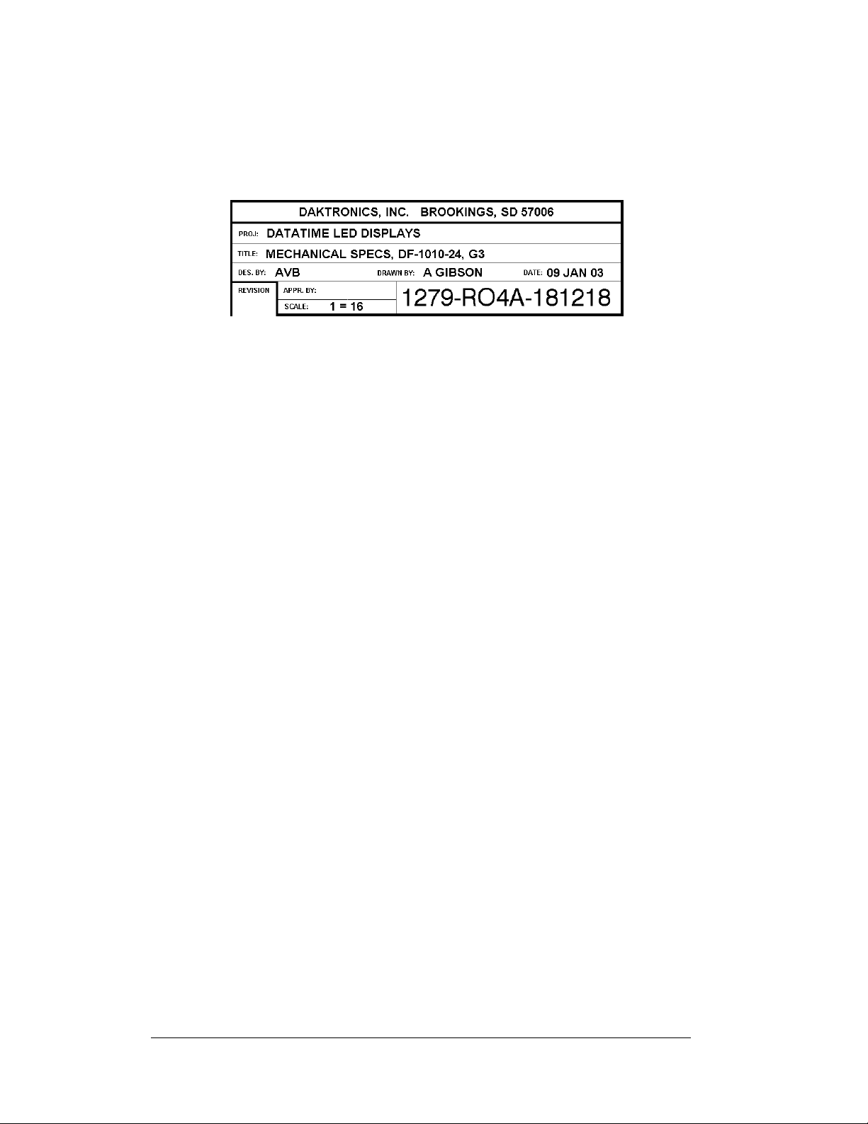
Figure 1 illustrates the Daktronics drawing label. The drawing number is located in the
lower-right corner of the drawing. Listing the last set of digits and the letter preceding them
identifies drawings in the manual. In the example the drawing would be referred to as
Drawing A-181218. Reference drawings are inserted in Appendix A.
Figure 1: Daktronics Drawing Label
All references to drawing numbers, appendices, figures, or other manuals are presented in
bold typeface, as shown below.
“Refer to Drawing A-181218 in Appendix A for the display dimensions.”
Additionally, any drawings referenced within a particular subsection are listed at the
beginning of that subsection in the following manner:
Reference Drawing:
Mechanical Specs, DF-1020-13, G3...................................... Drawing A-181220
The model numbers of a Daktronics display can be found on the ID label on the display. The
label will be similar to the one shown in Figure 2. When calling Daktronics Customer
Service, please have this information available to ensure that your request is serviced as
quickly as possible.
Figure 2: Display Identification Label
Daktronics displays are built for long life and require little maintenance. However, from time
to time, certain display components may need replacing. The Replacement Parts List in
Section 4 provides the names and numbers of components that may need to be ordered during
the life of the display. Most display components have a white label that lists the part number.
The component part number is in the following format: 0P-____-____ (component) or 0A____-____ (multi-component assembly).
Following the Replacement Parts List is an explanation of Daktronics Exchange and
Repair and Return Programs in Section 4.7. Refer to these instructions if any display
component needs replacement of repair.
1-2 Introduction
Page 9

1.1 Safety Precautions
Important Safeguards:
1. Read an d understand these instructions before installing your
display.
2. Do not drop the controller or allow it to get wet.
3. Prop erly ground the display with a ground rod at the sign
location.
4. Disconnect power when the display is not in use.
5. Disconnect power when servicing the display.
6. Do not modify the display structure or attach any panels or
coverings without the express written consent of Daktronics,
Inc.
1.2 Network Concepts
The concept of using LED displays as a cost effective, high impact method of
communication is rapidly growing throughout many industries and businesses.
There are three communication methods available: Current Loop, Radio, and
Modem.
Current Loop
The DataMaster controller connects to the Rate Display either from a j-box located
outside near the display or from an indoor location. The communication method is
current-loop to the host display, and from the host to the client. Current-loop is a
standard communication method that uses a maximum cable length of 600 meters
(approximately 2000 feet). Refer to Section 3 for additional information and
connections.
Radio
The radio network is a standard communication method that uses radio waves at high
frequencies to transmit signal. The radio network has a maximum distance of 450
meters (approximately 1,500 feet). A nearly straight line-of-sight path must be
maintained between the Server Radio connected to the DataMaster controller,
through a signal converter, and the Client Radio connected to the d isplay. Refer to
Section 3 (Electrical Installation) and the Section 5 (Rate Display Operation) for
additional information.
Modem
The modem is a standard communication interface that utilizes standard phone
transmission lines. The phone company assigns each phone line a number that the
modem uses to communicate between DataMaster and display. Each modem
network needs to have a dedicated phone line assigned to it. Refer to Section 3
(Electrical Installation) and the Section 5 (Rate Display Operation) for additional
information.
Introduction 1-3
Page 10

1.3 Product Overview
DataMaster Rate Displays are part of a family of Daktronics products designed for
easy installation, readability, and reliability.
The DataTime/DataMaster Series includes:
• Rate Displays: two- or four-digit signs, typically used to display
hotel/motel room rates or commodity prices.
• Gasoline Price Displays: gas price signs with three standard digits,
decimal, and
• Lottery Displays: Three digit signs typically used to display lottery
jackpots.
• Parking Garage Displays: four-digit display used for parking locations
requiring a DataMaster, switch inputs or third-party software.
• Event Counters: These displays are typically used to count to a designated
goal. They will count either up or down, and can be up to 9 digits long.
• Time & Temperature Displays: Automatic time & temp signs capable of
displaying temperatures in Fahrenheit or Celsius (three digits, degree
symbol, and F and C character) and 12- or 24-hour time.
The DataMaster series includes rate, gasoline, and parking displays, along with
lottery and event counters. The DataTime series name is used for time and
temperature displays only.
These displays have the following features:
• These displays use LEDs to illuminate their numeric digits.
• Power usage for individual displays in this series is a maximum 300 W. All
models have a 120 V power requireme nt .
• All DataMaster displays are configured with red or amber LEDs.
• DataMaster cabinets are constructed of heavy-gauge aluminum.
• Digit faceplates are black, and they are set directly into the surface of the
display.
• Mounting weights and dimensions for each model are listed in Section 2 of
this manual.
• The DataMaster outdoor LED displays have been desi g ned for use wi t h a
DataMaster
for display control. Section 5 of this manual provides operating
instructions.
The DataMaster model numbers are described as follows: DF-1030-HH-C or
DF-1040-HH-C
DF-1030
DF-1040
HH =
C =
9
/
fraction.
10
™
100 hand-held controller. The device uses a keyboard insert
=
Outdoor Digit Display (DF-1030 displays use two digits and
the DF-1040 displays use four digits)
Digit height in inches (13, 18, 24, 36 and 48)
LED Color- R (Red) or A (Amber),
1-4 Introduction
Page 11

1.4 Component Identification
The following terms include some of the more commonly used terms when referring
to these displays. Because Daktronics occasionally alters standard design to meet
customer needs, the actual display design may vary slightly from the illustrations
below.
This is only a brief overview. Refer to Secti
maintaining the various display components.
Client: The client display contains a client driver t
driver on the Signal IN terminals. These drivers can re-drive signal to other client
drivers.
DataMaster Controller (DM-
the time, date, hold times, dimming etc. on the Rate Display. See Section 5 for more
information on the DataMaster controller.
Display address: T
driver in a network. The address is set using an 8-position binary switch on the driver
board. For single-line signs such as a Rate Display or Time & Temp display, the
address will typically be “1”. If more than one display is used, the top display is
often set to address “1” and the others are set to “2”, “3” etc. The address will be
displayed each time the display powers up.
Digit circuit board: The
back of a digit panel. Problems with individual digits, segments or LEDs may require
accessing or replacing this board.
Host/primary: T
from the DataMaster controller on its Signal IN terminals. It is the only driver
connected to the temperature/photo sensor. The Signal OUT terminal block is used to
connect to client driver. The host driver is selected by inserting the Protocol 4 plug
into the protocol jack.
LED (light emitting diode):
Mirror/slave:
Power supply: Converts AC line voltage from the load center to low DC voltage for
one o
r more digit circuit boards.
Protocol plug: The
host driver for a set of host-client displays.
e display address is an identification number assigned to each
h
LE
e host display contains the host driver which relays signal directly
h
receives a
signal from the master but does not have a driver.
p
rotocol-4 plug is inserted in the 5-pin protocol jack to select the
): The handheld keyboard like device used to set
100
Ds are mounted to a circuit board, which mounts to the
LEDs are
o
high-intensity, low-energy lighting units.
n 4 for additional information on
hat receives signal from the “host”
Introduction 1-5
Page 12

1.5 Daktronics Nomenclature
To fully understand some Daktronics drawings, such as schematics, it is necessary to
know how various components are labeled in those drawings. You will find this
information useful when trying to communicate maintenance or troubleshooting
efforts.
In addition, the following labeling formats might be found on various Daktronics
drawings:
• “TB _ _” denotes a termination block for power or signal cable.
• “E _ _” denotes a grounding point.
• “J _ _” denotes a power or signal jack.
• “P _ _” denotes a power or signal plug for the opposite jack.
Finally, Daktronics part numbers are commonly found on drawings. Those part
numbers can be used when requesting replacement parts from Daktronics Customer
Service. Take note of the following part number formats. (Not all possible formats
are listed here.)
• “0P- _ _ _ _- _ _ _ _” denotes an individual circuit board , such as a drive r
board.
• “0A-_ _ _ _ - _ _ _ _” denotes an assembly, such as a circuit board and the
plate or bracket to which it is mounted. A collection of circuit boards
working as a single unit may also carry an assembly label.
• “W- _ _ _ _ ” denotes a wire or cable. Cables may also carry the assembly
numbering format in certain circumstances. This is especially true for
ribbon cables.
Most circuit boards and components within this display carry a label that lists the
part number of the unit. If a circuit board or assembly is not listed in the
Replacement Parts List in Section 4.6, use the label to order a replacement. A
typical label is shown in
Figure 3. The part number is in bold.
1-6 Introduction
Figure 3: Typical Label
Page 13

Section 2: Mechanical Installation
Note: Daktronics does not guarantee the warranty in situations where the display is not
constantly in a stable environment.
Daktronics engineering staff must approve an
of the display. If any modifications are made, detailed drawings of the changes must be
submitted to Daktronics for evaluation and approval, or the warranty may be void.
Daktronics is not responsible for installati
structures done by others. It is the customer’s responsibility to ensure that a qualified
structural engineer approves the structure and any additional hardware.
2.1 Mechanical Installation Overview
Mechanical installation typically consists of mounting the display and any
accompanying panels to the support structure.
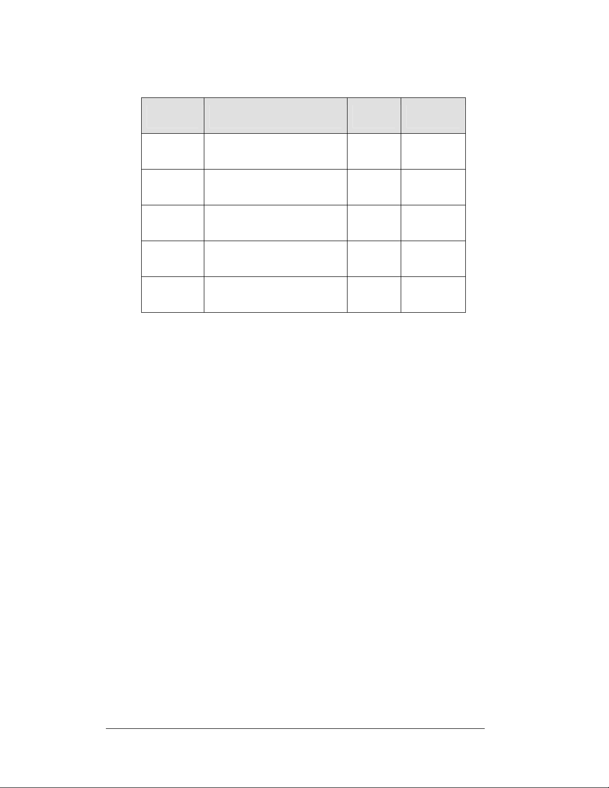
The table below shows all of the weights and dimensions for each model in this
seri
es. M
odels are listed in order by digit size
Two-Digit Displays (DF-1030 Series) – Dimensions and Weights
y c
hanges that may affect the weather-tightness
of structural integrity of support
ons
Model
DF-1030-13
DF-1030-18 H2’-0", W2’-6", D6"
DF-1030-24
DF-1030-36
DF-1030-48
Dimensions
Height, Width, Depth
H1’-6", W2’-0", D6"
(457 mm, 609 mm, 152 mm)
(610 mm, 762 mm, 152 mm)
H2’-6", W3’-0", D6"
(762 mm, 914 mm, 152 mm)
H3’-6", W4’-6", D8"
(1067 mm, 1372 mm, 203 mm)
H4’-6", W6’-0", D8"
(1372 mm, 1829 mm, 203 mm)
Weight Digit Size
20 lb
9 kg
30 lb
14 kg
45 lb
20 kg
95 lb
43 kg
135 lb
61 kg
13"
(330 mm)
18"
(457 mm)
24"
(610 mm)
36"
(914 mm)
48"
(1219 mm)
Mechanical Installation 2-1
Page 14
Four-Digit Displays (DF-1040 Series) – Dimensions and Weights
Model
DF-1040-13 H1’-6", W4’-0", D6"
DF-1040-18 H2’-0", W5’-0", D6"
DF-1040-24 H2’-6", W6’-0", D6"
DF-1040-36 H3’-6", W7’-6", D8"
DF-1040-48 H4’-6", W9’-0", D8"
Dimensions
Height, Width, Depth
(457 mm, 1219 mm, 152 mm)
(610 mm, 1524 mm, 152 mm)
(762 mm, 1829 mm, 152 mm)
(1067 mm, 2591 mm, 203 mm)
(1372 mm, 2743 mm, 203 mm)
2.2 Support Structure Design
Reference Drawings:
Mounting Method, Flag Style, One Pole...................... Dra
Mounting Method, Single Line on One Pole
While DataMaster outdoor digit displays are designed for wall or pole mounting, every
installation will be different. Actual site demands will dictate the appropriate mounting
method. Most DataMaster models have fully finished exteriors, but other models are
designed to be inserted into an existing sign cabinet and require a custom installation.
Drawing A-166139 an
display on a single column support to multiple displays stacked above one another in a
two-pole installation. The drawings include welding and hardware notes that will be
applicable for most installations.
Note: T
specifications for
he drawings suggest mounting methods and are not to be considered as
construction. It is the installer’s responsibility to ensure the
mounting structure and hardware is capable of supporting the sign, and will
agree with local codes.
-166142 detail a number of mounting methods, from a single
d A
Weight Digit Size
35 lb
16 kg
60 lb
27 kg
90 lb
41 kg
95 lb
43 kg
135 lb
61 kg
13"
(330 mm)
18"
(457 mm)
24"
(610 mm)
36"
(914 mm)
48"
(1219 mm)
wing A-166139
................ Drawing A-166142
2-2 Mechanical Installation
Page 15

2.3 Lifting the Display
Model DF-1030/DF-1040 displays are shipped equipped with 3/8" eyebolts that are
used for lifting and positioning the modules. Eyebolts are located along the top outer
edges of the cabinet.
Daktronics strongly recommends using a spreader bar, or lifting bar, to lift the
display. Using a spreader bar ensures that the force on the eyebolts is straight up,
minimizing lifting stress.
incorrect (right example) method for lifting a display. Lift the display as shown on
the left, with a lifting bar. Be sure to use every lifting point provided.
Figure 4 illustrates both the correct (left example) and the
Figure 4: Lifting the Display
Note: Daktronics assumes no liability for display damage or injury resulting
from incorrect setup or incorrect lifting methods.
Eyebolts are intended for lifting during installation only. Do not attempt to
permanently support the display by the eyebolts.
In installations in which an ad panel or some other display section may be added to
the base display, the lower section is installed first and secured to the support beams,
and then the upper section is placed atop or above the lower sign section and
attached to the beams. There may be cables extending from the top of the lower
section. Guide these cables into the hole in the bottom of the upper section for later
connection.
Installers may remove the lift eyebolts once the display is in place. If removing the
eyebolts, adequately seal the holes using bolts and sealing washers. In addition,
inspect the top and sides of the display for any holes or openings that may allow
moisture to enter the display, and plug and seal those openings with silicone.
Mechanical Installation 2-3
Page 16

Page 17

Section 3: Electrical Installation
Daktronics outdoor displays are ETL listed and tested to CSA standards for outdoor use.
Contact Daktronics with any questions regarding the testing procedures.
Only qualified individuals should perform power routing and termination to the display.
It is
the re
sponsibility of the electrical contractor to ensure that all electrical work meets
or exceeds local and national codes.
3.1 Preparing for Power/Signal Connection
Reference Drawings:
Quick Install, DF-1030 & DF-1040 Rate Displays........Dra
Electrical installation consists of the following processes:
• Pr
oviding power and ground to a disconnect near the display.
• Routing power and ground from the main disconnect to the display
ver/power enclosure.
dri
• Co
nnecting the display ground to a grounding electrode at the sign location .
• Routing the control signal cable from the control location to the sign
lo
cation.
Drawing A-177150
DataMaster Rate Displays, including hookup of the connections between ho st and
client displays. Refer to this drawing before undertaking any part of the electrical
installation.
p
rovides instructions for power and signal connections for the
wing A-177150
3.2 Power and Ground Connections
Correct power and grounding installation is imperative for proper display operation.
The subsections that follow give details of display power installation. Only qualified
individuals should attempt to complete the electrical installation. Improper
installation could result in serious damage to the equipment and could be hazardous
to personnel.
Power
Daktronics DataMaster displays have been designed for easy access to components,
and the power and control signal hookup has been simplified. Front panels are
hinged to allow access to the digits, cabling, and other electronic components.
The DataMaster Rate Displays require a dedicated, 120 V circuit for incoming
po
r. The display itself has no breakers or fuses.
we
Electrical Installation 3-1
Page 18
WARNING: It is critical that the display circuit be fused at 15 A, and that all
conductors used must be designed to pass a 15 A current in normal operation.
Failure to meet wiring and over current protection device requirements is a
violation of the National Electrical Code
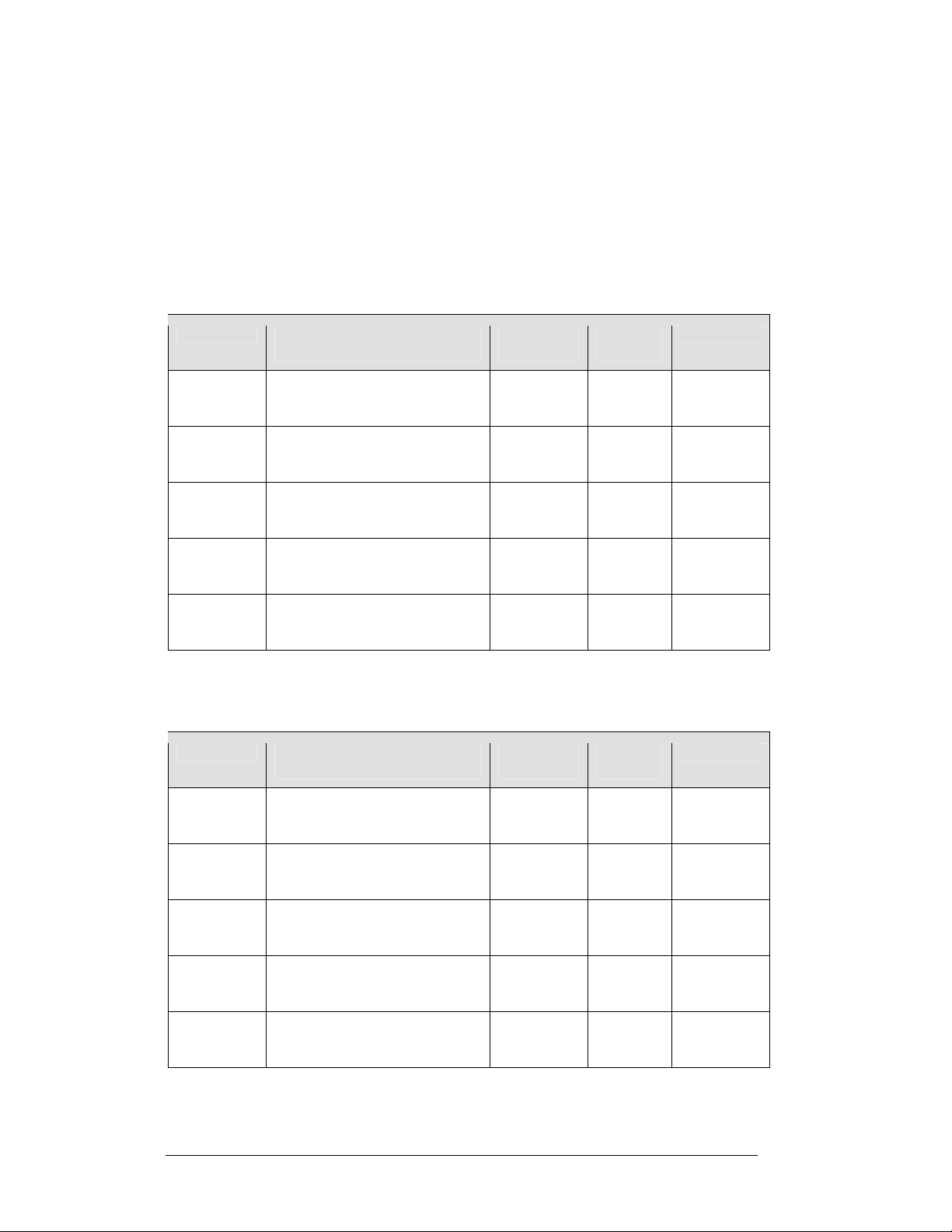
The tables below show the circuit specifi
for each model in this series. Models are listed in order by digit size.
Two-Digit Displays (DF-1030 Series) – Dimensions and Weights
®
and will void the display warranty.
ions and maximum power requirements
cat
Model Dimensions
Height, Width, Depth
DF-1030-13 H1’-6", W2’-0", D6"
(457 mm, 609 mm, 152 mm)
DF-1030-18 H2’-0", W2’-6", D6"
(610 mm, 762 mm, 152 mm)
DF-1030-24 H2’-6", W3’-0", D6"
(762 mm, 914 mm, 152 mm)
DF-1030-36 H3’-6", W7’-6", D8"
(1067 mm, 1372 mm, 203 mm)
DF-1030-48 H4’-6", W6’-0", D8"
(1372 mm, 1829 mm, 203 mm)
Four-Digit Displays (DF-1040 Series) – Dimensions and Weights
Model Dimensions
Height, Width, Depth
Maximum
Wattage
150 W
150 W
150 W
300 W
300 W
Maximum
Wattage
Circuit Digit Size
120 V AC
1.3 A
120 V AC
1.3 A
120 V AC
1.3 A
120 V AC
2.5 A
120 V AC
2.5 A
13"
(330 mm)
18"
(457 mm)
24"
(610 mm)
36"
(914 mm)
48"
(1219 mm)
Circuit Digit Size
DF-1040-13 H1’-6", W4’-0", D6"
(457 mm, 1219 mm, 152 mm)
DF-1040-18 H2’-0", W5’-0", D6"
(610 mm, 1524 mm, 152 mm)
DF-1040-24 H2’-6", W6’-0", D6"
(762 mm, 1829 mm, 152 mm)
DF-1040-36 H3’-6", W7’-6", D8"
(1067 mm, 2286 mm, 203 mm)
DF-1040-48 H4’-6", W9’-0", D8"
(1372 mm, 2743 mm, 203 mm)
150 W
150 W
150 W
300 W
300 W
120 V AC
1.3 A
120 V AC
1.3 A
120 V AC
1.3 A
120 V AC
2.5 A
120 V AC
2.5 A
13"
(330 mm)
18"
(457 mm)
24"
(610 mm)
36"
(914 mm)
48"
(1219 mm)
3-2 Electrical Installation
Page 19

Grounding
Reference Drawings:
Schematic; Multipurpose 4 Col. LED Drvr...................Draw
Schematic; 16 Col Multipurpose LED Drvr..................Draw
Enclosed Driver, 4 Col. Reference...............................Draw
ing A-165028
ing A-179599
ing A-184918
Displays MUST be grounded according to the provisions outlined in Article 250 of
the National Electrical Code and according to the specifications in this manual.
Daktronics requires a resistance-to-ground of 10 ohms or less.
The contractor performing the electrical installation can verify ground resistance.
Tech
cians from Daktronics Sales and Service offices can also provide this service.
ni
The display system must be
c
onnected to an earth electrode installed at the display.
Proper grounding is necessary for reliable equipment operation. It also protects the
equipment from damaging electrical disturbances and lightning. The display must be
properly grounded, or the warranty will be void. Refer to Drawing A-184918, for
information on where to connect the earth-ground electrode. Connection at the driver
enclosure terminal block is illustrated at the bottom of the drawing.
The material for an earth-ground electrode diffe
from region to region and may
rs
vary according to conditions present at the site. Consult the National Electrical Code
and any local electrical codes that may apply. The support structure of the display
cannot be used as an earth-ground electrode. The support is generally embedded in
concrete, and if it is in earth, the steel is usually primed or it corrodes, making it a
poor ground in either case.
Power Installation
There are two considerations for power installatio
n
: installation with ground and
neutral conductors provided, and installation with only a neutral conductor provided.
These two power installations differ slightly, as described in the following
paragraphs:
Installation with Ground and Neutral Conductors Provided. For this type of
in
stallatio
n, the power circuit must contain an isolated earth-ground conductor.
Under this circumstance, do not connect neutral to ground at the disconnect or at the
display. This would violate electrical codes and void the warranty. Use a disconnect
so that all hot lines and neutral can be disconnected. The National Electrical Code
requires the use of a lockable power disconnect within sight of or at the display.
Installation with Only a Neutral Conductor Provided. Installatio
s where no
n
grounding conductor is provided must comply with Article 250-32 of the National
Electrical Code. If the installation in question meets all of the requirements of Article
250-32, the following guidelines must be observed:
• Connect the
grounding electrode
cable at the local disconnect, never at the
display driver/power enclosur e.
• Use a
disconnect that opens all of the ungrounded phase conductors.
Electrical Installation 3-3
Page 20
3.3 Lightning Protection
The use of a disconnect near the display to completely cut all current-carrying lines
significantly protects the circuits against lightning damage. The National Electrical
Code also requires it. In order for this device to provide protection, the power must
be disconnected when the display is not in use. The control console should also be
disconnected from power and from the signal j-box when the system is not being
used. The same surges that may damage the display's driver can also damage the
driver console's circuit.
3.4 Power and Signal Connection
Reference Drawings
Multipurpose 4 Column
LED Driver II Specifications.................................. Drawing A-166216
Quick Install, DF-1030 & DF-1040
Rate Displays........................................................ Drawing A-177150
16 Col. MASC Driver Specification.............................. Drawing A-184475
Enclosed Driver, 4 Column Reference........................ Drawing A-184918
Electrical Specification Drawings .............................Refer to Appendix A
Route power and signal cables into the display from the side or rear. There are
knockouts for
back panels. All power and signal wiring terminates at the driver enclosure.
Refer to Drawing A-177150 for a complete review of power and signal connections
for DataMaster Rate displays. Drawings A-184918 and A-184475 illustrate and
provide connection specifications for the 4- and 16-column drivers used in all
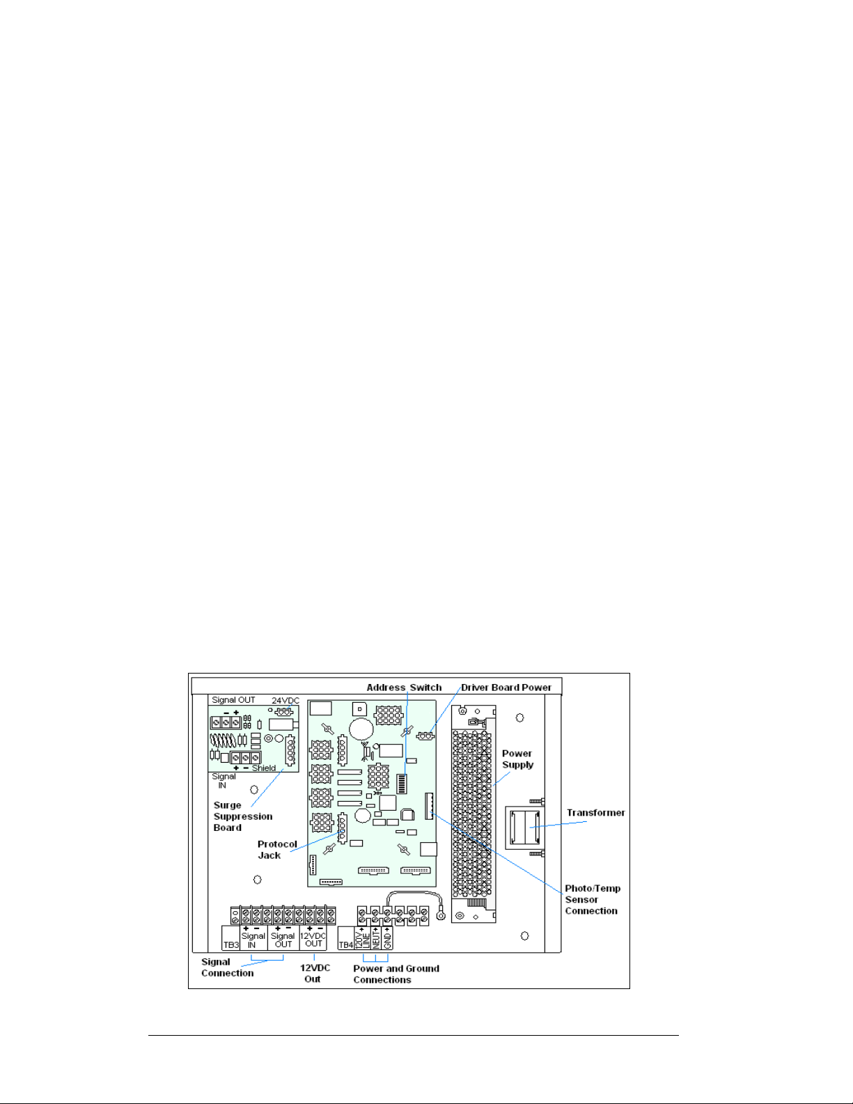
DataMaster Rate displays. The schematics for drivers detail both the wiring in the
enclosure and external connections to the display. Power and signal connections,
illustrated in Figure 5, are similar for both drivers.
1
/2" conduit fittings on the sides of all DataMaster cabinets and on the
7
/8"
Figure 5: DataMaster Driver Enclosure with 4-Column Driver
3-4 Electrical Installation
Page 21
To gain access to the driver enclosure, open the access door and remove the cover
from the enclosure. Refer to the Electrical Specifications Drawings for the access
location for your sign. For 13", 18" and 24" displays, access to the interior
components is gained by removing the screws from the hinged door. In the 36" and
48" displays, there are door latches, providing for access to the interior components
by removing the digits.
Current Loop (Direct)
Reference Drawings:
Riser Diagram, Outdoor Wire Control..........................Drawing A-164988
Riser Diagram, Indoor Wire Control.............................Drawing A-175342
Quick Install, DF-1030 & DF-1040 Rate Displays........Drawing A-177150
Enclosed Driver, 4 Column..........................................Drawing A-184918
A direct controlled display uses a current loop connection from the j-box at the base
of the display to the driver enclosure in the sign. All the power and signal wiring
terminates at the driver enclosure. The DataMaster hand-held controller receives its
power from the display. The display layout is shown in Drawing A-177150.
Note: The cable from the j-box to the display needs to be routed through conduit or
the display pole to protect it from weather and vandalism.
1. Mount the j-box near the display.
2. Rou te a 6-conductor, 22 AWG, shielded cable through conduit from the j-
box to the driver enclosure in the host display. (Distance limit from the jbox to the display is 50 ft.)
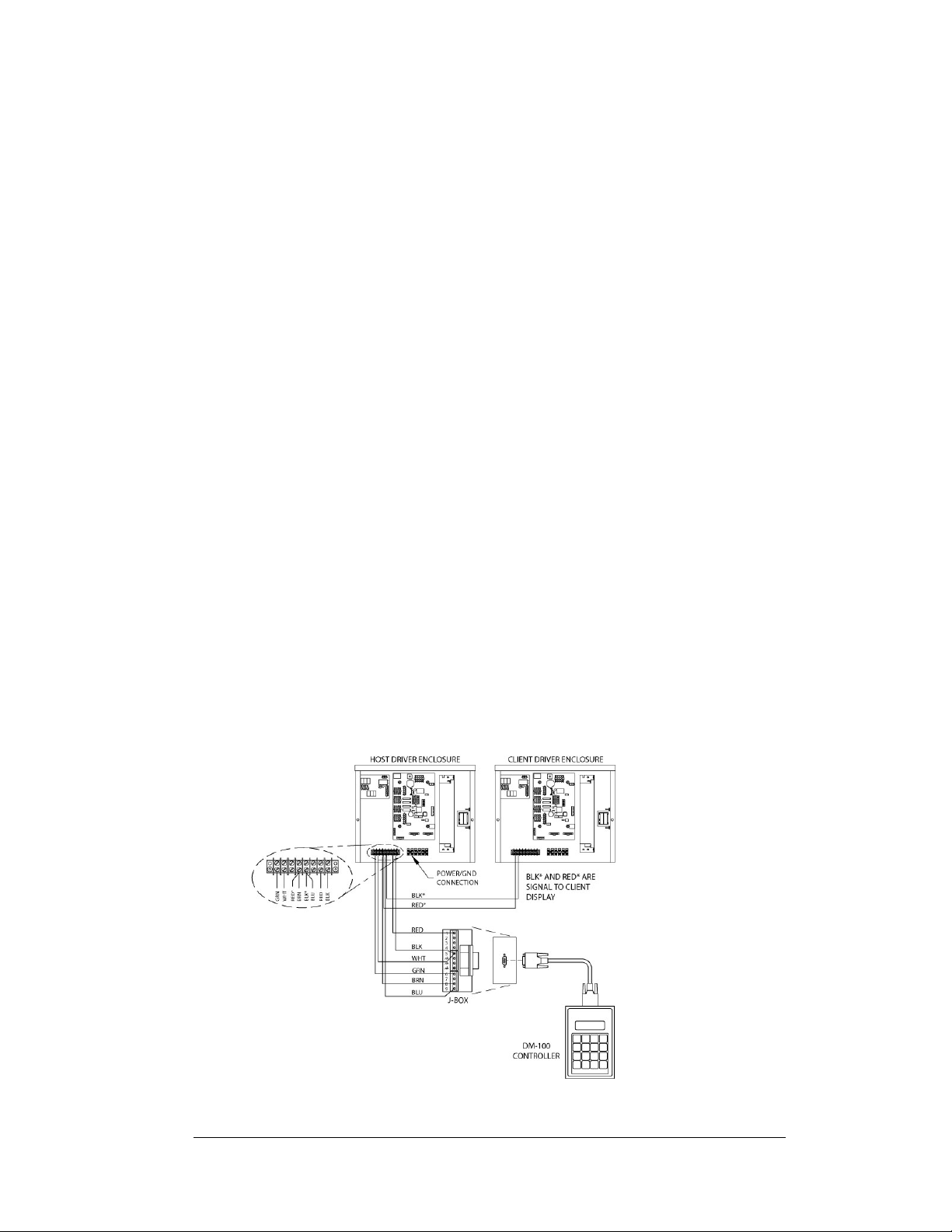
3. Connect the signal/power cable from the j-box to the driver enclosure as
shown in
A-184918 for additional information.
4. Using a DB9M to DB9F serial cable, plug the DataMaster controller into
the j-box, connected to the host display driver enclosure.
Figure 6 and listed in the table. Refer to Drawings A-164988 and
Figure 6: Direct Current Loop Connection
Electrical Installation 3-5
Page 22
J-Box to Driver Enclosure Input Jack
J-Box
Pin#
Pin 1 Red 12V DC Out (+) pin 7
Pin 5 Black 12 V DC Out (-) Pin 8
Pin 5 White Signal IN (-) Pin 2
Pin 6 Green Signal IN (+) Pin 1
Pin 8 Brown Signal OUT (+) Pin 4
Pin 9 Blue Signal OUT (-) Pin 5
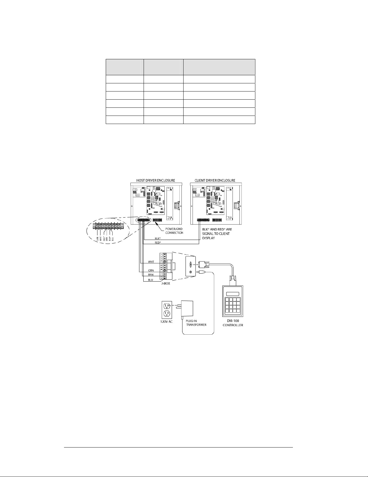
If using the DataMaster handheld controller at an indoor location, two pairs of signal
wires (white/green and blue/brown) will need to be connected to the j-box. A wall
pack transformer, plugs into the indoor j-box, and provides power to the DataMaster
controller. The distance from the indoor j-box to the host driver can up to 2000 ft.
Refer to Figure 7
and Drawing A-175342 for system layout and signal connections.
Cable
Color
Enclosure Terminal
Block
Figure 7: Direct Connection from Indoor Location
Radio (Direct)
Reference Drawings:
Quick Install, DF-1030 & DF-1040 Rate Displays....... Drawing A-177150
System Riser Diagram, Server/Client Setup............... Drawing A-199834
A radio controlled display uses the DataMaster controller connected to a j-box. The
j-box is then wired to a server radio attached to the building. A second radio, called
the client is connected to the Rate display. The DataMaster hand-held controller and
server radio receive their power through the j-box. A wall pack transformer powers
the j-box. The client radio receives its power from the display. The display layout is
shown in Figure 8
3-6 Electrical Installation
and Drawing A-199834.
Page 23
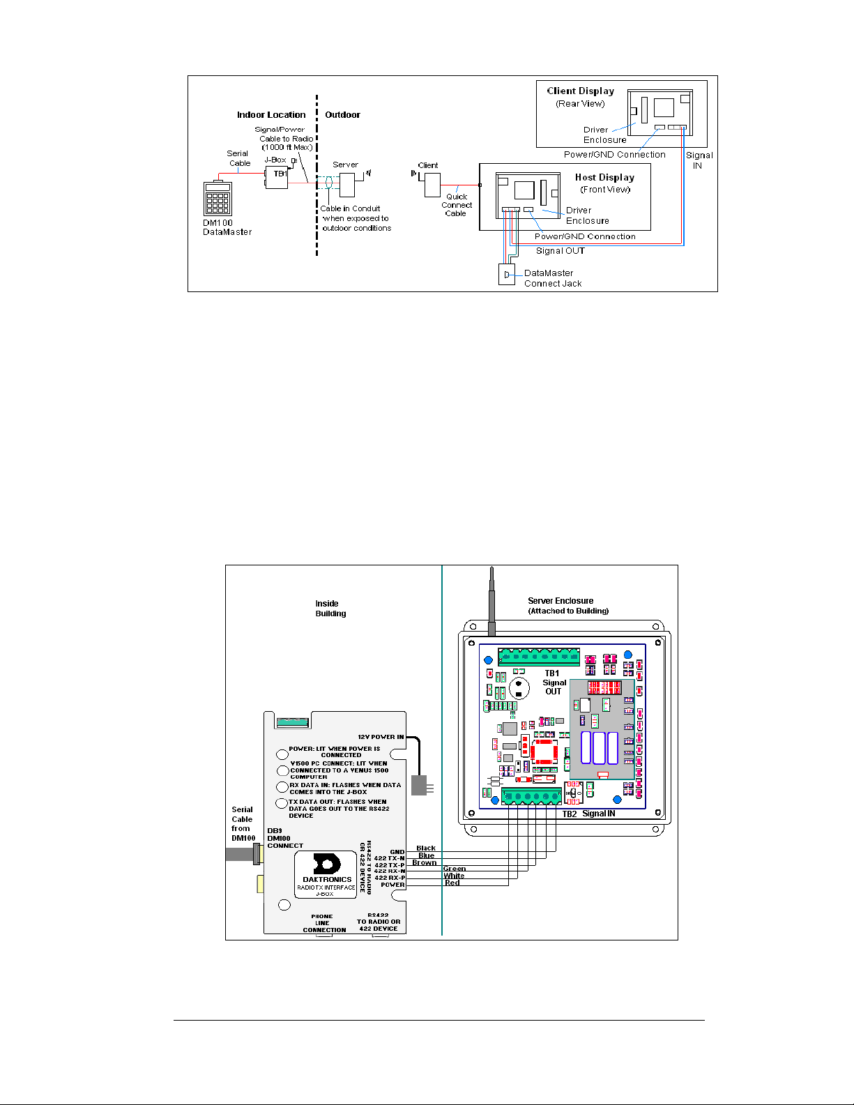
Figure 8: Radio Controlled Display Layout
1. Using the DB9M to DB9F serial cable, connect from the DataMaster
controller to the j-box, at the “DB9 Male, DataMaster 100 connect” jack.
2. Using an 18-AWG, 6-conductor, shielded cable, (W-1370) connect fr om
the j-box jack labeled “RS422 to Radio or 422 Device” to the TB2 jack
on the Server radio, mounted to the building. See
below for cable connections from the j-box to the radio.
3. Plug the wall pack transformer into th e j-box and then into a 120V
grounded outlet.
4. Mount the Client radio on the display or display pole, and within 25 feet
of the display.
5. Plug the quick connect cable from the client radio into the 6-pin quick
connect jack on the side of the Rate Display.
Figure 9 and the table
Figure 9: Direct Current Loop Connection
Electrical Installation 3-7
Page 24
Connection from J-box to Server Radio Enclosure
J-Box TB2 on Server
Pin# Function
Pin 1 Power Red Pin 1 Power
Pin 2 422 RX-P White Pin 2 422 TX-P
Pin 3 422 RX-N Green Pin 3 422 TX-N
Pin 4 422 TX-P Brown Pin 4 422 RX-P
Pin 5 422 TX-N Blue Pin 5 422 RX-N
Pin 6 GND Black Pin 6 GND
Notes:
1. The cable from the client radio to the display can to be routed through
conduit or the display pole to protect it from weather and vandalism. The
cable is weather and sunlight resistant.
2. The Server and Client radios must have a clear line-of-sight path and not be
more than 1500 feet apart.
3. A current-loop j-box is often mounted at the base of the display pole in case
of problems with communication though the radio network.
4. For ad ditional connection and operation information see ED-13894:
DataMaster Radio Installation Manual.
Cable
Color
Pin# Function
Modem (Indirect)
Reference Drawings:
Modem Installation; 4 Col MASC Drvr. Enc. ............... Drawing A-177039
Quick Install, DF-1030 & DF-1040 Rate Displays....... Drawing A-177150
System Riser Diagram, Modem Setup........................ Drawing A-200552
A modem controlled display uses a DataMaster controller connected to a modem/
j-box, to call a second modem in the Rate Display. The DataMaster hand-held
controller will receive its power from the j-box. A wall pack transformer powers the
j-box. The display layout is shown in
Figure 10 and Drawing A-200552.
Figure 10: Modem Controlled Display Layout
3-8 Electrical Installation
Page 25
1. Using the DB9M to DB9F serial cable, connect from the DataMaster
controller to the modem/J-box, at the “DB9 Male, DataMaster 100
connect” jack.
2. Connect a phone line from a phone junction box on the wall to the
modem/j-box jack labeled “Phone Line Connection.”
3. Plug the wall pack transformer into th e modem/j-box and then into a
120V grounded outlet.
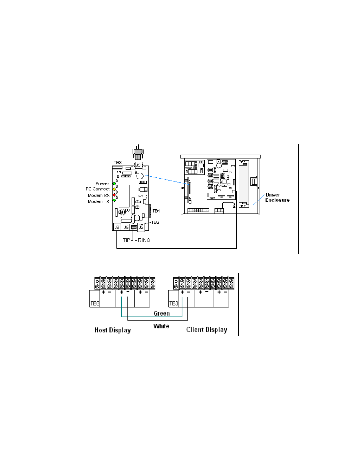
4. At the display, the local phone company must provide a dedicated phone
line to the display and identity the color used for the tip wire and which
color is for the ring wire.
5. The tip and ring phone wires will terminate to TB2 on the modem as
shown in Figure 12 and Drawing A-177039. If a phone cable is used
inside the display, it will plug into J5.
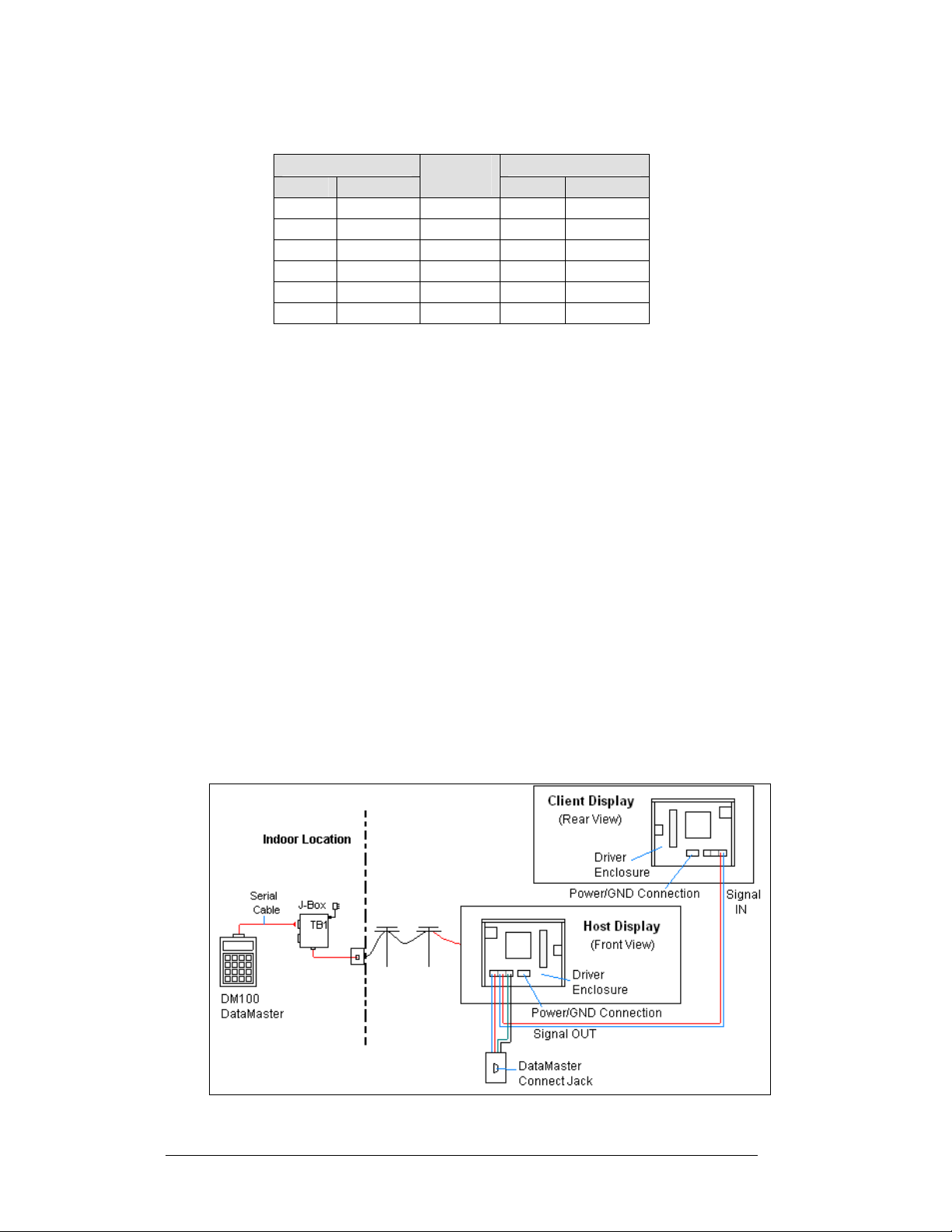
Figure 12: Phone line Connection to Display Modem
Figure 11: Host, Signal Out to Client, Signal In
Notes:
1. A current-loop j-box is often mounted at the base of the display pole for
communication in the case of problems with the modem network.
2. The phone line and display power cannot be routed though the same
conduit.
3. For ad ditional operation and connection information see ED-13953:
DataMaster Modem Installation Manual.
Electrical Installation 3-9
Page 26
Host/Client Definitions and Address Settings
Reference Drawings:
4 Column MASC Driver Specifications........................ Drawing A-166216
8 Column MASC LED Driver Specifications................ Drawing A-167237
16 Col. MASC Driver Specifications............................ Drawing A-184475
Host/Client Definitions................................................. Drawing A-185236
Host/Client Definitions
One driver at each sign installation is designated as the “host driver.” This driver
receives its signal directly from the controller on the “Signal IN” terminals, and it is
the only driver that is connected to the photo/light sensor. The “Signal OUT”
terminals are used to connect to “client drivers.” Refer to Drawing A-185236 for an
illustration of the client/host driver display setups.
Select the host driver by inserting the Protocol 4 plug into the 5-pin protocol jack
(J20.) For protocol jack location, refer to Drawings A-166216, A-167237 or
A-184475 for your specific display driver.
The 12 V DC terminals connected to the host driver (see “Signal Connections” in
Figure 5) run to the controller junction box. This output is used to power the
DataMaster 100 controller.
All other drivers in the display system are client drivers. These drivers receive signal
from the host driver on the “Signal IN” terminals and can re-drive this signal to other
“client drivers” on the “Signal OUT” terminals.
Some multiple-module signs use “mirror/slave displays.” The term s “m aster/slave”
or “primary/mirror” should not be confused with “host/client. ” Mirror/slave displays
do not contain a driver and may use either the client or host digit outputs.
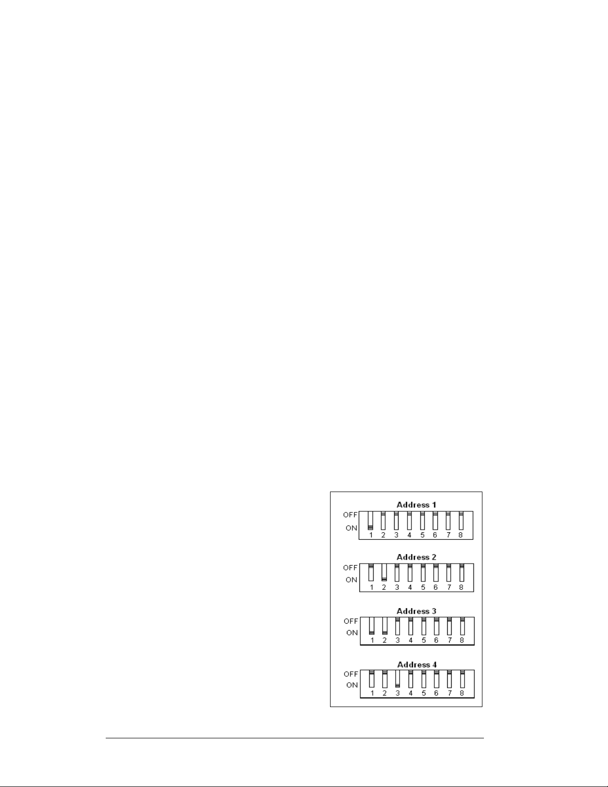
Address Settings
The address of each driver is set using an
8-position DIP-switch (S1), and the address
is based on that driver’s position in the sign
or display system. If a single-line sign is
used, the address will typically be Address
“01.” This means that switch 1 is turned
“ON” and the remaining 7 switches are in
the “OFF” position. This is the default
address set when each display is shipped. In
multiple-product displays, the address
determines which line of information is
shown on the driver’s digits. The switch is
set using a binary address. Use the table and
the examples in
Figure 13 for setting the
address.
Figure 13: Example Address Settings
3-10 Electrical Installation
Page 27
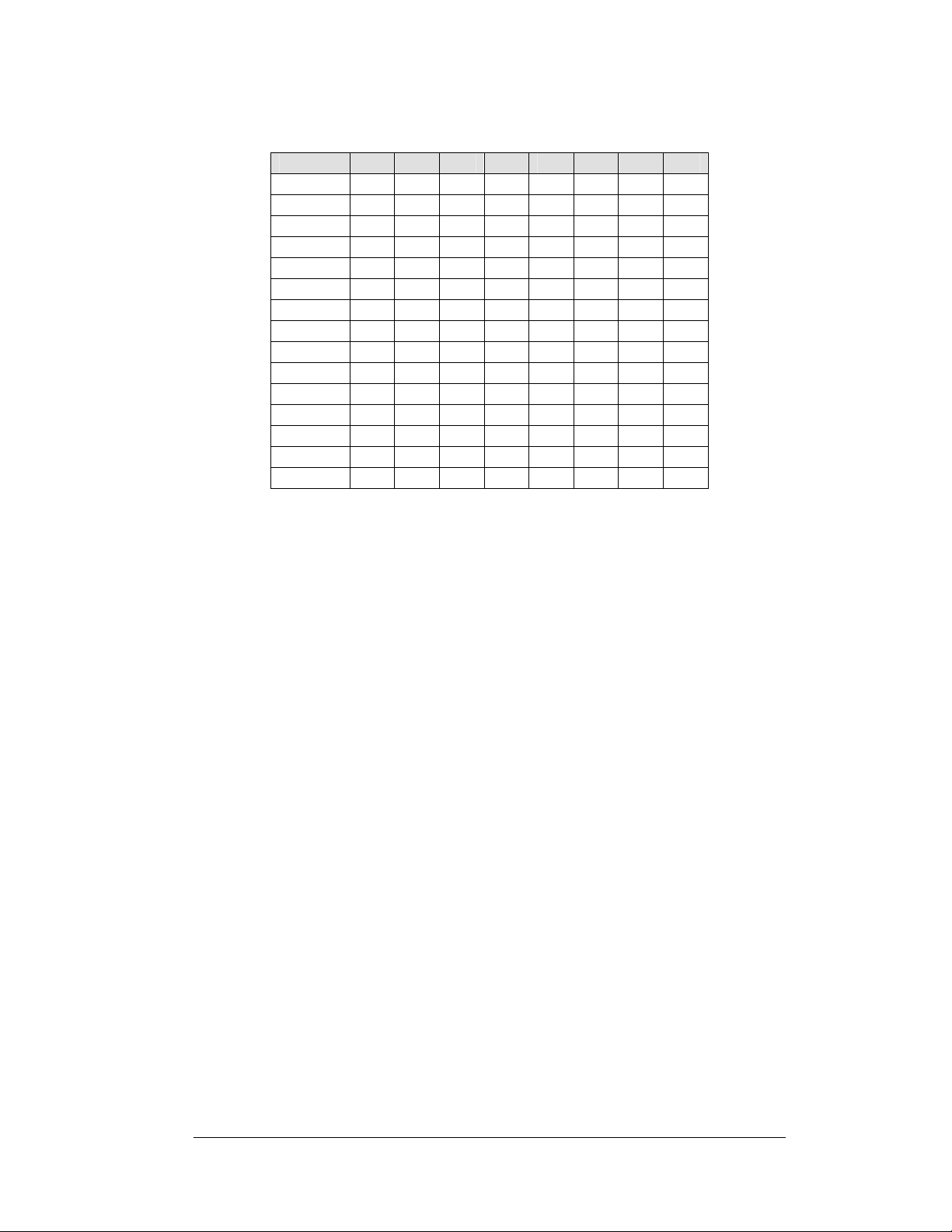
Binary Address Settings
Address 1 2 3 4 5 6 7 8
1 ON OFF OFF OFF OFF OFF OFF OFF
2 OFF ON OFF OFF OFF OFF OFF OFF
3 ON ON OFF OFF OFF OFF OFF OFF
4 OFF OFF ON OFF OFF OFF OFF OFF
5 ON OFF ON OFF OFF OFF OFF OFF
6 OFF ON ON OFF OFF OFF OFF OFF
7 ON ON ON OFF OFF OFF OFF OFF
8 OFF OFF OFF ON OFF OFF OFF OFF
9 ON OFF OFF ON OFF OFF OFF OFF
10 OFF ON OFF ON OFF OFF OFF OFF
11 ON ON OFF ON OFF OFF OFF OFF
12 OFF OFF ON ON OFF OFF OFF OFF
13 ON OFF ON ON OFF OFF OFF OFF
14 OFF ON ON ON OFF OFF OFF OFF
15 ON ON ON ON OFF OFF OFF OFF
Note: Some older drivers set the address of each dri
plug (Daktronics part # 0A-1279-0122) in J19. The address, either using a switch or
a plug, needs to be set for each driver.
ver using a 12-position address
Electrical Installation 3-11
Page 28

Page 29

Section 4: Display Maintenance
and Troubleshooting
IMPORTANT NOTES:
1. Disconnect power before doing any repair or maintenance work on the
display!
2. Allow only qualified service personnel access to internal display
electronics.
3. Disconnect power when not using the display.
4.1 Cabinet Specifications
Reference Drawings:
Mechanical Specification Drawings .........................Refer to
Cabinets for the Daktronics outdoor LED digit displays are constructed of heavygauge al
chart in Section 2. Hinged panels for servicing digits and indicators and for
component access are detailed in each model's Mechanical Specifications Drawing.
inum. Exact dimensions and weights for each model are listed in the
um
Appendix A
4.2 Component Location and Access
Reference Drawings:
Electrical Specification Drawings............................. Refer to
Mechanical Specification Drawings .........................Refer to
Displays in the DataMaster Rate Display series are made up of two main
com
Display Digits:
Each host or primary display (the mirror
contains an enclosure that includes the following devices:
nts: the circuit boards that make up the digits and the driver enclosure.
pone
• A si
• The digits for 24”, 36” and
• The 4-digit Rate displays are made up of two different digit sizes, which
• Display
• 24V DC power supply
• 10V AC transformer
• Signal/Power Input Terminal Jack
• Signal Board (Surge board on direct displays or a modem)
• Light (photo) sensor connection
ngle circuit board makes up the digits for the 13” and
48” are made up of LED segments
vary
depending on the display size
does
not contain a driver enclosure)
Driver
Appendix A
Appendix A
18” digits
Maintenance and 4-1
Troubleshooting
Page 30

For the front-access modules in this series, opening the hinged access doors on the
front of the display or removing one of the digits can reach all internal electronic
components and digits.
For the 13”, 18” and 24” displays the hinged door swings outward when the two
screws on the display face panel are removed, as shown in Figure 14. For the large
displays, the enclosure is reached by removing one of the digits from the face of the
display. Since component placement varies slightly with each DataMaster model,
consult the Electrical and Mechanical Specifications Drawings.
Figure 14: DataMaster Rate Display with Door Panels Open
Note: Disconnect power before servicing the display! Disconnect power, too,
when the display is not in use. Prolonged power-on may shorten the life of some
electronic components.
4.3 Service and Diagnostics
Replacing a Digit
The digit circuit board, the platform for the LEDs, is mounted to the back of the digit
panel. Do not attempt to remove individual LEDs. In the case of a malfunctioning
board, replace the entire digit panel (13” and 18” displays). Refer to Figure 15 for the
digit assembly.
To remove a display digit, follow these steps:
1. Open the digit panel as described in the preceding section.
2. Disconn ect the power/signal connector from the back of the digit. Release
the connector by squeezing together the locking tabs as you pull the
connector free.
4-2 Maintenance and
Troubleshooting
Page 31

3. The digits are secured to the
inside of the panel with fixed
machine screws, spacers, and
push nuts. Remove the nuts
and lift the digit off the
standoff screws. (The push
nuts can be removed in several
ways, but Daktronics
recommends using a
driver.)
4. Position a new digit ov er the
screws and tighten the nuts.
5. Reconnect the power/signal
connector.
Note: This is a keyed
connector it will attach in one
way only. Do not attempt to
force the connection!
6. Close and secure the digit
panel and test the display.
9
/32" nut
Figure 15: Digit Assembly
Replacing a Digit Segment
When a digit segment malfunctions, in most cases it is necessary to just replace that
segment board. The larger digits (24", 36", 48"), as shown in
of LED segments. As with smaller digits, the digit segment circuit boards are
mounted to the back of the digit panel. Do not attempt to remove individual LEDs.
To remove a digit segment, follow these steps:
1. Open the digit panel as described above.
2. Disconnect the 2-pin power/signal
connector from the back of the
individual segment. Release the
connector by squeezing together the
locking tabs as you pull the connector
free.
3. The individual segments are secured to
the inside of the panel with fixed
machine screws, spacers, and push nuts.
Remove the nuts and lift the segment
off the standoff screws.
4. Position a new segment over the screws
and tighten the nuts.
Figure 16: Segmented Digit Panel (Rear View)
5. Reconnect the power/signal connector.
Note: This is a keyed connector it will attach in one way only. Do not
attempt to force the connection!
6. Close and secure the digit panel and test the display.
Replace a malfunctioning colon, decimal, or indicator assembly in the same manner.
Figure 16, are made up
Maintenance and 4-3
Troubleshooting
Page 32

Segmentation and Digit Designation
Reference Drawing:
Segmentation, 7 Segment Bar Digit.............................. Drawing A-38532
In each digit, certain LEDs always
go on and off together. These
groupings of LEDs are referred to
as “segments.” Drawing A-38532
illustrates digit segmentation. It
also details which connector pin is
wired to each digit segment and the
wiring color code used throughou t
the display.
The Electrical Specification
Drawings specify the driver
connectors controlling the digits.
Numbers displayed in hexagons in
the upper half of each digit, as
shown in
Figure 17, indicate which
Figure 17: Digit Designation
connector or connectors are wired to that digit. Larger digits, like the 36" digits
shown in Figure 17, are each wired to two connectors. (Digits for a 48” display use
four connectors for each digit.)
Replacing an LED Driver
Reference Drawings:
4 Column MASC LED Driver Specifications................ Drawing A-166216
8 Column MASC Driver Specifications........................ Drawing A-167237
16 Col. MASC Driver Specification.............................. Drawing A-184475
Electrical Specification Drawings .............................Refer to Appendix A
Mechanical Specification Drawings..........................Refer to Appendix A
Drivers are typically mounted inside the display and immediately behind a digit, but
location and mounting varies by model. Refer to the Electrical and Mechanical
Specification Drawings for the location of your driver. All displays in this manual
are front-accessible.
To replace the driver in the display enclosure:
1. Open the digit panel or display face panel as described in Section 4.2.
2. Remove the cover from the driver enclosure.
3. It is helpful to have the cables labeled as to which was removed from which
connector.
4. Disconnect all connectors from the driver. Release each connector by
squeezing together the locking tabs as you pull the connector free.
Note: When reconnecting, remember that these are keyed connectors and
will attach in one way only. Do not attempt to force the connections.
5. Remove the wing nuts securing the driver to the inside of the enclosure.
4-4 Maintenance and
Troubleshooting
Page 33

6. Carefully lift the driver from the display and place it on a clean, flat surface.
7. Follow the steps in reverse order to attach a new driver.
DataMaster Rate displays may use 4-, 8-, or 16 -column drivers, depending on the
model and size of digits. Each 16-column is so named because it has 16 outputs as
compared to 8- and 4-column drivers.
Figure 18 identifies the major functions for a 4-column driver. (Major functions are
the same on the 8- and 16-column drivers.)
Figure 18: 4-column Digit Driver
In the display, the LED drivers perform the task of switching digits on and off. Refer
to Drawings A-166216, A-167237, or A-184475 for a complete listing of driver
connector functions and wiring pin numbers for the correct driver for your display.
The following table lists the functions of the various jacks, including those that are
not used in this application.
Maintenance and 4-5
Troubleshooting
Page 34

LED Driver Jack Functions
Jack Number Function
J1-J4 (4-column)
J1-J8 (8-column)
J1-J16 (16-column)
J17
J20
J23
J24
TB1
J19
J18, J21, J22, J25, J26, J27,
J28
The display line controlled by the driver is set with a DIP-switch that is set at the
factory before shipment. (Note: Some older drivers use a 12-pin address plug
inserted in J19). All DataMaster displays ship with the “Line 1” address already set.
Digits Output
Signal/Power Input
Protocol-5 Location
12 VDC Power Out
Modem
CAN (photo sensor)
Address Plug (older drivers only)
Jacks not used in this application
Replacing a Signal Surge Board
Reference Drawings:
Enclosure Driver, 4 Column Reference....................... Drawing A-183775
Electrical Specification Drawings .............................Refer to Appendix A
Mechanical Specification Drawings..........................Refer to Appendix A
The surge board is mounted inside the display enclosure and behind a digit, but
location and mounting varies by model. Refer to the Electrical and Mechanical
Specification Drawing for the location of your surge board. All displays are
front-accessible.
1. Open the digit panel or display face panel as described in Section 4.2.
2. Remove the cover from the driver
enclosure.
3. Disconnect all connectors from the
surge board. Release each connector by
squeezing together the locking tabs as
you pull the connector free.
Note: When reconnecting, remember
that these are keyed connectors and will
attach in one way only. Do not attempt
to force the connections.
4. Remove the nuts securing the driver to
the inside of the enclosure.
5. Carefully lift th e surge board from the
display and place it on a clean, flat surface.
6. Follow the steps in reverse order to attach a new driver.
Figure 19: Signal Surge Suppression Board
4-6 Maintenance and
Troubleshooting
Page 35

In the display, the signal surge suppression board is an inline device used to filter the
current loop data line. It suppresses surges down to a low voltage to protect the display’s
controller. Refer to Drawing A-184918 for the location of the surge board inside the
driver enclosure. The surge board is pre-wired before the display is shipped.
Note: The surge suppressor must be firmly connected to the driver enclosure, and the
display must be properly grounded in order to be effective.
Replacing a Modem
Reference Drawings:
Modem Installation; 4 Col MASC Driver Enc.....................................A-177039
Electrical Specification Drawings ................................... Refer to Appendix A
Mechanical Specification Drawings................................ Refer to Appendix A
If a modem is included with the display, it is mounted inside the display enclosure,
behind a digit, and near the driver but the location and mounting varies by model.
Refer to Drawing A-177039 and the Electrical and Mechanical Specification
Drawings for the location of the modem. All displays in this series are front-accessible.
1. Open the digit panel or display face panel as described in Section 4.2.
2. Remove the cover from the driver enclosure.
3. Disconnect all connectors from the modem. Release each connector by
squeezing together the locking tabs as you pull the connector free.
Note: When reconnecting, remember that these are keyed connectors and will
attach in one way only. Do not attempt to force the connections.
4. Remove the nuts securing the modem to the inside of the enclosure.
5. Carefully lift the modem from the display and place it on a clean, flat surface.
6. Follow the steps in reverse order to attach a new modem.
LEDs
The modem has four LEDs.
• The power LED (DS1) should remain lit while
power is applied to the modem.
• The modem RX (DS3) and TX (DS4) LEDs are
normally off, but will flash when
communicating.
• The carrier detect LED (DS5) will light when the
modem has established communication to
another modem.
Input/Output Jacks
The modem board also has several input and output jacks:
• TB2 is a phoenix connector to terminate the tip
and ring wires.
• J3 is the AC power input into the modem board
from the transformer in the driver enclosure.
• J6 is the RS232, RJ45 output jack from the modem board to the display
driver.
Maintenance and 4-7
Troubleshooting
Figure 20: Modem Board
Page 36

• J5 is an RJ11 jack for termination of a pre-terminated phone line (if
needed).
• J2, TB1, and TB3 are not used in this application.
4.4 Light/Photo Sensor Installation
Reference Drawing:
Light Sensor Installation, G3 ....................................... Drawing A-183775
Mechanical Specification Drawings..........................Refer to Appendix A
Displays in the DataMaster series use a light sensor to regulate sign dimming
functions. Use Drawing A-18377 5 and the following instructions to install the photo
sensor in your DataMaster Rate display. If the sign or sign system has more than one
display, install the light sensor in the primary/host display only.
1. Remove the screws on the front of the display and
open the hinged access door.
2. Locate and remove the
panel of the display. The location of the plug varies
by model. Refer to the Mechanical Specification
Drawings for model-specific information.
3. Ther e are two 6-32 studs above and below the
plughole. Position the internal light sensor
assembly (Daktronics part #0A-1279-0203) is
positioned on the studs, with the clear lens toward
the front of the cabinet and the cable at the bottom.
Secure the sensor with the provided plastic wing
nuts.
4. Route the signal cable to the driver and insert the
6-postion plug into the mating jack on the driver,
TB1.
5. Close the hinged access doors and replace the
screws.
5
/8" plastic plug from front
Figure 21: Internal Light Sensor
4.5 Troubleshooting
This section lists potential problems with the display, indicates possible causes, and
suggests corrective action. This list does not include every possible problem, but it
does represent some of the more common situations that may occur. (Refer to the
appropriate manual for a list of potential problems with add-on or separately
mounted message centers.
Symptom/Condition Possible Cause
Entire display fails to work • Check for proper line voltage at termination pan el
• Check connections from power supply to driv er
• Check power LED on driver and power suppl ies
4-8 Maintenance and
Troubleshooting
Page 37

Symptom/Condition Possible Cause
Cannot communicate with display
via current loop
Cannot communicate with display
via radio
Cannot communicate with display
via modem
Garbled display • Internal driver logic malfunction
Digit will not light • Black wire to digit broken
Segment will not light • Broken LED or connection
Segment stays lit • Driver shift register failure
Data appears in the wrong place
on the display, wrong data on a
particular line of the display
• Check connections at j-box and display
• Make sure DataMaster is rece
• Check seri
• Check for power to signal converter connected to
server
• Check wiring from signal converter to server
• Check conn
• Make sure DataMaster an
• Verify the correct phone number
• Check the tip a
at the display
• Make sure di
• DataMaster ma
• Poor contact at driver con
• Driver malfun
• Broken wire between driver and digit
• Poor contact at driver con
• Short circuit on digit
• Incorrect addr
“Power On Self-Test” in the following section, and
consult tables to set correct addresses.)
al cable from DataMaster to j-box
ections from Client to display
nd ring connections to the modem
splay and DataMaster have power
lfunction
ction
e
ss settings on drivers (Refer to
iving power
d display have power
nection
nector
Some displays have their own built-in troubleshooting mechanism. Failures that may
occur in the display driver are described using codes. In the event a sign
malfunctions, a failure code registers by displaying an “E (x)” value on the first two
digits of the display. “E” simply indicates an error, and the letter “x” represents the
actual code number. Refer to the following table for a description of each failure
code and for possible solutions.
Note: Th
co
DataMaster sign.
e LCD screen on the DataMaster 100 controller will not show the failure
des described in the following table. Failure codes will be displayed only on the
Maintenance and 4-9
Troubleshooting
Page 38

Failure Code Description Possible Solution
E1 Protocol Setting Error: There is an
unsupported driver protocol
setting.
E4 No Message Error: T his code is
shown when there are no
messages downloaded to the
display
E5 No Line Number Selected Error:
The driver for this line has a
Protocol 4 plug installed in J20,
but all address switches are
“OFF”. (Note: in some older
drivers this happens when no
address plug is installed in J19.)
Check the value set in the protocol
plug of the driver (J20).
Download a new message to the
display using the <
SEQUENCE
100 controller.
Set the line number by setting the
binary address on S1 (or installing
the correct plug in J19). The
Protocol 4 plug designates this
driver as the “host.” If this is not the
host, remove the Protocol 4 plug
from J20.
> key on the DataMaster
Power On Self-Test:
A useful troubleshooting tool is the power on self-test the host driver performs every
time it powers up:
• If the signal wiring between each controller is correct, the first two digits of
each driver will display “Ad” momentarily, and the first digit will then flash
three numbers indicating the decimal address that is set with the address
plug in J19. (If a client driver displays “A <number>,” followed by
“P<number>,” it is not receiving “signal in,” and is performing its own
• self-test.)
• Next, the first two digits of each line will display “Lx”, where “x” is the line
number that the driver is set to control (set with address plug).
• Finally, each line will display “1234…” according to the column number of
each of its digits. Every line should show “1” on the left-most digit, and all
digits should be numbered consecutively from left to right. If this is not the
case, either the wrong address plug is installed, or the driver or digit harness
is connected incorrectly.
If there is no address set (or address plug installed) on the host driver, the host driver
will display “E5,” and all client drivers will continually cycle through the power on
self-test.
DISPLAY
4-10 Maintenance and
Troubleshooting
Page 39

4.6 Replacement Parts
Refer to the following table for Daktronics replacement parts.
Maintenance and 4-11
Troubleshooting
Page 40

Description
Daktronics
Part No.
Driver, 4-column 0P-1192-0068
Driver, 8-column 0P-1192-0082
Driver, 16-column 0P-1192-0086
Light sensor, G3 0A-1279-0203
Protocol plug (Protocol 4) 0A-1279-0089
Transformer, Pri. 115V; Sec. 10 VCT@1.2A T-1072
Transformer, wall pack (for DataMaster 100 and signal
converter)
Power supply, 24 V DC, 150 W A-1720
Address #1 Plug (older drivers)
Communication Boards and Accessories
Signal surge suppression board 0P-1110-0011
Modem, RS232 coated, internal 0P-1279-0003
J-box, signal converter, w/modem 0A-1279-0162
J-box, signal converter, radio 0A-1279-0161
T-1118
0A-1150-0122
RJ11 to RJ45, M-M, straight, 18” cable 0A-1137-0300
Server Radio, outdoor
Client Radio, w/Quick Connect 0A-1146-0078
Cable, 6-cond., 18 AWG, j-box to Server Radio W-1370
Transformer, wall pack (for j-box/signal converter) T-1118
DataMaster 100 Controller Parts
DataMaster 100 hand-held controller 0A-1196-0088
Junction box, outdoor, 9-pin D-male 0A-1196-0093
Junction box, indoor, 9-pin D, male 0A-1196-0099
DataMaster 100 outdoor wired installation kit 0A-1279-0087
DataMaster 100 indoor wired installation kit 0A-1279-0103
Transformer, wall pack (for DataMaster 100) T-1118
Cable, serial, DB9 male to DB9 female W-1267
DM-100 Insert Time & Temp/Rate Display 0G-164998
0A-1146-0079
4-12 Maintenance and
Troubleshooting
Page 41

Digits and Accessories
Digit, 13" red, pc board 0P-1192-0200
Digit, 13" amber, pc board 0P-1192-0214
Digit, 18" 7-segment, red, pc board 0P-1192-0202
Digit, 18" 7-segment, amber, pc board 0P-1192-0216
Digit, 13" 7-segment, red, w/ faceplate 0A-1192-0223
Digit, 13" 7-segment, amber, w/ faceplate 0A-1192-0224
Digit, 18" 7-segment, red, w/ faceplate 0A-1192-0227
Digit, 18" 7-segment, amber, w/ faceplate 0A-1192-0256
Digit, 24" 7-segment, red, w/ faceplate 0A-1192-2231
Digit, 24" 7-segment, amber, w/ faceplate 0A-1192-2232
Digit segment, 24" red, vert 0P-1192-0204
Digit segment, 24" red horiz. 0P-1192-0 205
Digit segment, 24" amber, vert 0P-1192-0218
Digit segment, 24" amber horiz. 0P-1192-0219
Digit, 36" 7-segment, red, w/faceplate 0A-1192-2260
Digit, 36" 7-segment, amber, w/faceplate 0A-1192-2261
Digit segment, 36" red, vert 0P-1192-0208
Digit segment, 36" red horiz. 0P-1192-0 209
Digit segment, 36" amber, vert 0P-1192-0222
Digit segment, 36" amber horiz. 0P-1192-0223
Digit, 48" 7-segment, red, hinged 0A-1279-0181
Digit, 48" 7-segment, amber, hinged 0A-1279-0182
Digit segment, 48" red, vert 0P-1192-0212
Digit segment, 48" red horiz. 0P-1192-0 213
Digit segment, 48" amber, vert 0P-1192-0226
Digit segment, 48" amber horiz. 0P-1192-0227
Colon, 13" red, pc board (used in DF-1010-13) 0P-1192-0236
Colon, 13" amber, pc board (used in DF-1010-13) 0P-1192-0237
Indicator, 2" red, pc board (18" and 24" displays) 0P-1192-0228
Indicator, 2" amber, pc board (18" and 24" displays) 0P-1192-0229
Indicator, 4" red, pc board (36" and 48" displays) 0P-1192-0244
Indicator, 4" amber, pc board (36" and 48" displays) 0P-1192-0245
Indicator, 4" red w/ face plate (36" and 48" displays) 0A-1192-2434
Indicator, 4" amber w/ face plate (36" and 48" displays) 0A-1192-2435
Maintenance and 4-13
Troubleshooting
Page 42

4.7 Daktronics Exchange and Repair and Return Programs
To serve customers' repair and maintenance needs, Daktronics offers both an
Exchange Program and a Repair and Return Program. Daktronics' unique Exchange
Program is a quick, economical service for replacing key components in need of
repair. If a component fails, Daktronics sends the customer a replacement, and the
customer, in turn, sends the failed component to Daktronics. This not only saves
money but also decreases display downtime.
Daktronics provides these plans to ensure users get the most from their Daktronics
p
oducts, and it offers the service to qualified customers who follow the program
r
guidelines explained below. Please call the Help Desk – 877-605-1113 – if you have
questions regarding the Exchange Program or any other Daktronics service.
When you call the Daktronics Help Desk, a trained service technician will work with
y
o solve the equipment problem. You will work together to diagnose the problem
ou t
and determine which exchange replacement part to ship. If, after you make the
exchange, the equipment still causes problems, please contact our Help Desk
immediately.
If the replacement part fixes the problem, package
and wrapping in which the replacement part arrived, fill out and attach the enclosed
UPS shipping document, and RETURN THE PART TO DAKTRONICS. In most
circumstances, you will be invoiced for the replacement part at the time it is shipped.
This bill is due when you receive it.
Daktronics expects immediate return of an exchange part if it does not solve the
problem
damaged due to acts of nature or causes other than normal wear and tear.
If the defective equipment is not shipped to Daktronics within 30 working days from
th
be invoiced for it. This second invoice represents the difference between the
exchange price and the full purchase price of the equipment. The balance is due
when you receive the second invoice. If you return the exchange equipment after 30
working days from the invoice date, you will be credited for the amount on the
second invoice, minus a restocking fee.
To avoid a restocking charge, please retur
days from the invoice date.
Daktronics also offers a Repair and Return program for items not subject to
excha
Return Materials Authorization: To
representative prior to shipment to acquire a Return Material Authorization (RMA)
number. If you have no local representative, call the Daktronics Help Desk for the
RMA. This expedites repair of your component when it arrives at Daktronics.
.
The company also reserves the right to refuse equipment that has been
oice date, it is assumed you are purchasing the replacement part, and you will
e inv
n
ge.
return parts for service, contact your local
the
defective part in the same box
n the
defective equipment within 30
4-14 Maintenance and
Troubleshooting
Page 43

Packaging for Return: Package an
in shipment. Electronic components such as printed circuit boards should be installed
in an enclosure or placed in an antistatic bag before boxing. Please enclose your
name, address, phone number and a clear description of symptoms.
This is how to reach us:
Mail: Custom
Daktronics, Inc.
PO Box 5128
331 32nd Ave
Brookings SD 57006
Phone:
o
Fax: 6
E-ma
Daktronics Help Desk: 877-605-1113 (toll free)
r 605-697-4034
05-697-4444
il: h
elpdesk@daktronics.com
Service
er
d pad the item well so that it will not be damaged
Maintenance and 4-15
Troubleshooting
Page 44

Page 45

Section 5: Rate Display Operation
This section describes the DataMaster 100 controller, and how it is used to set the information
on the Rate Display.
5.1 DataMaster 100 Overview
The DataMaster 100 Series controller, shown in
Figure 22, is a hand-held controller designed to
operate Daktronics LED DataMaster
console’s liquid crystal display (LCD) guides the
user through the operation of the system.
The DataMaster 100, identified by the series
number DM-100, can be configured to display
motel rates, gasoline price, and time and
temperature data. The displays in the LED
DataMaster Series will use a junction box at the
base of the sign, an indoor wire system, modem or
radio. Refer to Section 3 for information on
possible connection procedures.
For details on configuring the DataMaster to
operate a display, refer to Section 5.3: Rate
Display Operation.
displays. The
Figure 22: DataMaster 100
5.2 DataMaster Insert and Code
Reference Drawing:
System Riser Diagram, Control Combinations............Drawing A-164988
The DataMaster 100 uses a keypad insert to
program rate information into Daktronics
LED DataMaster Rate Displays.
Figure 23 illustrates the DM-100 insert
used to control the displays. For details on
the insert, refer to the DataMaster 100 insert
drawings, Drawing A-164988.
If an insert is lost or damaged, a copy of the
insert drawing located in Appendix A can
be used until a replacement is ordered.
To start the controller and use the insert,
read the next section carefully to fully
understand the operation instructions.
Figure 23: DataMaster 100 Insert, LL2551
Display Operation 5-1
Page 46

5.3 Rate Display Operation
The DataMaster 100 controller can be configured to program price variances
displayed on the LED DataMaster Rate sign. The instructions provided in this
section discuss the functions the operator uses to control the Rate display. In the
unlikely event that the Rate Display malfunctions, refer to Appendix B for the
Frequently Asked Questions section for this display.
Connect the display with the DataMaster. Often when using either a modem or radio
an
output j-box will also be connected for use if the other means of communication
fails.
Note: T
way is by using the menu and then the arrows to reach the desired programming
location. The other way is to set the first gas price and then continue to enter through
the additional screens.
Rate Display Startup
To operate the DataMaster Rate displays, the DataMaster 100 must first be
programmed to the rate display function. Use the <
startup. The following text will be displayed on the LCD during startup.
Daktronics, Inc.
Brookings, SD
DataMaster 100
ED-13374 V3.X
The controller will then list the “Current Function”, if it is Rate Display you can
cont
need to press <
Note: Press t
you miss this step, unplug the power to the DataMaster controller and start again.
Use the following table as a guide to startup procedures.
here is more than one way to get ce
nue, otherwise at the next frame: “Current Function? Press Set Function” you
i
CLEAR/SET FUNCTION> and use the < ↑↓> to select Rate Display.
e <
CLEAR/SET FUNCTION> key quickly to enter the function mode. If
h
rtain LCD screens on the DM-100. One
CLEAR/SET FUNCTION> key on
LCD Screen Action
CURRENT FUNCTION
RATE DISPLAY
Power is provided to the DM-100 through the
serial cabl
transformer, either directly or by way of the jbox/signal converter.
This display appears briefly.
e or through the wall pack
5-2 Display Operation
Page 47

CHANGE FUNCTION?
PRESS SET FUNCT
SELECT FUNCTION
RATE DISPLAY ↓↑
This message appears next on the screen.
If “RATE DISPLAY” was shown on the bottom
of the LCD
line
controller will automatically default to previous
Rate Display settings. (The controller will
remember the last function used, so you
should only have to do this with a new
controller or when switching between
DataMaster displays.)
If a function other than “RATE DISPLAY” was
w
n on the bottom line of the LCD during
sho
startup, press the <
the second LCD prompt is displayed.
You only have 1 or 2 seconds to push it. If you
miss it, unplu
try again.
Press the arrow up or down keys <↑↓> until
the rate display option is shown. Press the
ENTER> key to accept.
<
during startup, do nothing. The
SET FUNCTION> key while
g
the power to the DM-100 and
Note: The actual Rate Price values will not be displayed on the DataMaster 100
LCD sc
reen because these values are kept in the display itself.
Menu Items
Pressing the <MENU> key accesses the following settings:
1. Price Line 1
2. Price Line 2
3.
Price Line 3
4.
Price Line 4
5.
Price Line 5
6.
LED Test?
7.
Display Option
8.
Modem Settings
9.
Display Status
10
. Set Time 12HR
Use Me
numbered top to bottom with 1 being the top of the display. For further details, refer
to Modifying Price Line Settings discussed previously in this section.
Display Operation 5-3
nu items 1-5 to edit the price on each lin
he display. Lines are typically
e of t
Page 48

For more information about the Modem Settings submenu, refer to ED-1
3953:
DataMaster Modem Installation Manual. For additional information about the
Display Status or the Set Time submenus, refer to ED-13894: DataTime Radio
Installation Manual, ED-13894; that manual provides for complete details on
installation and setup for a bi-directional radio system.
Rate Display Controller Operation
The DataMaster 100, configured to the rate display option, defaults to showing the
current display settings on power up. The following text will be shown on the LCD.
LCD Screen Action
LINE PRICE
1 ↓ $ DD.CC
<EDIT> TO MODIFY
1 ↓ $ DD.CC
The display will toggle between these two
screens.
DD.CC = dollars and cents value shown on
line 1.
Press the up or down arrow keys <
scroll through the current setting for any of
the lines on the display.
Press the <
the line settings.
ENTER/EDIT> key to modify any of
↑↓> to
Modifying Price Line Settings
The rate price can be modified either by pressing the <EDIT> key durin g operation
(Refer to the Rate Display controller operation) or using the <
the <
MENU> key operation.)
Use the following key to identify the item to be edited.
L= Current line number to be edited
D.CC= Current dollars and cents value to edit
LCD Screen Action
EDIT LINE L
$DD.CC
Press any of the number keys to edit the price
value for this line.
Press <
press <
Note: The flashing asterisk on the LCD shows
the current data being edited.
Press the down arrow key <
next line, or press the <
the next item or the previous one on the list.
ENTER> to accept the new value or
CLEAR> to abort the changes.
MENU> key (refer to
↓> to modify the
↑↓> keys to move to
5-4 Display Operation
Page 49

LED Test
Select menu item 6, LED Test, to test the LED digits on the display.
LCD Screen Action
LED TEST
ENTER TO TEST
ENTER TO TEST
CLEAR TO EXIT
Display Option
Use the Display Option menu to select the display configuration.
LCD Screen Action
DISPLAY OPTION
$00.00 ↓
Press the <ENTER> key to cycle the display
digits between all LEDs on and all LEDs off.
Press <ENTER> send the test command to the
sign.
Press <
The current configuration is shown on the
bottom line of the LC
key to select any of the possible configuration
values.
Possible values are:
Select the configuration th
la
Note: If the wrong configuration is selected, the
digits shown on the LCD may not be displayed
correctly on the display.
Press <
next screen.
CLEAR> to exit the test mode
D. Press the down arrow
$00.00 (default)
$0.000
$.0000
$0000.00
$000.00
$00
at matches the
yout of your display.
ENTER> to accept and move on to the
Modem Settings
The following items for a modem can be set using the DM-100:
1. Dial Numb
2. Dial out prefix
Disconnect time
3.
Multiple Dial
4.
Display Operation 5-5
er
Page 50

Display Status
This will look for a bi-directional link to the display, and will allow you to send the
sequence changes.
Set Time
This allows you to set the time and date with the DM-100.
Dimming
The dimming level of the Rate display can be adjusted in two ways. A
temperature/light sensor, mounted near the display, can detect the level of ambient
light at the display location and dim the sign's LEDs accordingly. This function is
known as automatic dimming. When the manual dimming function is selected, the
LEDs remain at the same level of brightness regardless of the level of light detected
at the display.
To select either of these functions, press <
on the bottom line of the LCD.
LCD Screen Action
DIMMING>. The current setting is shown
DIMMING
AUTOMATIC ↓
Press the down arrow key <↓> to toggle
through dim settings:
Automatic – The dis
based on the light detected at the display
Manual – The display dimming level is set
manually
regardless of the level of light detected at the
display.
. Once set, this valu
play automatically dims
e remains
If AUTOMATIC dimming is selected, the following LCD prompt will be shown:
LCD Screen Action
SET AUTO DIMMING
MAX INTENSITY?
Press the <ENTER/EDIT> key to edit the auto
dimming max intensity. This is the maximum
intensity that the display will use in full-bright
modes (during daylight hours.)
Press <
dimming maximum setting
CLEAR> to keep the current auto
The following LCD prompt is shown for either
Manual or Automatic dimming
selections:
5-6 Display Operation
Page 51

LCD Screen Action
INTENSITY XX↓↑
ENTER TO SET
XX – Current intensity (1-16)
Max Intensity - 16
Press the up or down arrow key <↑↓> to modify
the current intensity of the display (Note: The
DataMaster must be connected to the display)
Press <
manual dimming mode is selected, this will be
the new intensity for the display. If the
automatic dimming mode is selected, the
display will illuminate in full-bright mode, which
is the maximum intensity level.
ENTER> to accept this intensity. If the
Display Sequence
Once connected to the display with a j-box, radio, or modem, press <DISPLAY
SEQUENCE
for a preview of the new sequence on the LCD.
> to display the new sequence on the display. This button will also allow
Display Operation 5-7
Page 52

Page 53

Appendix A: Reference Drawings
Drawings in this manual are referenced by their last set of digits and the letter
preceding them. Drawings in this appendix are listed in alphanumeric order.
Segmentation, 7 Segment Bar Digit...............................................................Draw ing A-038532
Riser Diagram; Outdoor Wire Control............................................................Drawing A-164988
Insert, 0G-164988 Price/ T&T Display...........................................................Dra
Schematic; Multipurpose LED Drvr................................................................Dra
Mechanical Specs, D-F-1030-36, G3.............................................................Dra
Electrical Specs, D-F-1030-36, G3................................................................Dra
Mechanical Specs, D-F-1040-36, G3.............................................................Dra
Electrical Specs, D-F-1040-36, G3................................................................Draw in g A-165838
Mounting Method, Flag Sty
Mounting Method, Single Line on One Pole ..................................................Dra
4 Column MASC Driver Specifications ..........................................................Dra
8 Column MASC Driver Specifications ..........................................................Dra
Riser Diagram, Indoor Wire Control...............................................................Draw
Modem Installation; 4 Col MASC Driver, Enclosure.......................................Drawing A-177039
Quick Install, DF-1030 & DF-1040 Rate Displays
Schematic; 16 Col Multipurpose LED Drvr ....................................................Dra
Mechanical Specs, DF-1030-13, G3..............................................................Drawing A-181237
Electrical Specs, DF-1030-13, G3
Mechanical Specs, DF-1030-18, G3..............................................................Dra
Electrical Specs, DF-1030-18, G3 .................................................................Drawing A-181242
Mechanical Specs, DF-1030-24, G3..............................................................Dra
Electrical Specs, DF-1030-24, G3
Mechanical Specs, DF-1040-13, G3..............................................................Drawing A-181249
Electrical Specs, DF-1040-13, G3
Mechanical Specs, DF-1040-18, G3..............................................................Dra
Electrical Specs, DF-1040-18, G3 .................................................................Drawing A-181252
Mechanical Specs, DF-1040-24, G3..............................................................Dra
Electrical Specs, DF-1040-24, G3
Mechanical Specifications, DF-1030-48, G3..................................................Drawing A-181674
Electrical Specs, DF-1030-48, G3
Mechanical Specifications, DF-1040-48, G3
Electrical Specs, DF-1040-48, G3 .................................................................Drawing A-181677
Light Sensor Installation, G3..........................................................................Dra
16 Col. MASC Driver Specification................................................................Draw
Enclosed Driver, 4 Column Reference...........................................................Dra
Host/Client Defi
System Riser Diagram, Server/Client
System Riser Diagram, Modem Setup...........................................................Draw in g A-200552
nitions ...................................................................................Drawing A-185236
le, One Pole........................................................Drawing A-166139
..........................................Draw in g A-177150
.................................................................Draw ing A-181238
.................................................................Draw ing A-181247
.................................................................Draw ing A-181250
.................................................................Draw ing A-181254
.................................................................Draw ing A-181675
..................................................Draw ing A-181676
............................................................Draw in g A-199834
wing A-164998
wing A-165028
wing A-165833
wing A-165834
wing A-165837
wing A-166142
wing A-166216
wing A-167237
ing A-175342
wing A-179599
wing A-181239
wing A-181243
wing A-181251
wing A-181253
wing A-183775
ing A-184475
wing A-184918
Reference Drawings A-1
Page 54

Page 55

Page 56

Page 57

Page 58

Page 59

Page 60

Page 61

Page 62

Page 63

Page 64

Page 65

Page 66

Page 67

Page 68

Page 69

Page 70

Page 71

Page 72

Page 73

Page 74

Page 75

Page 76

Page 77

Page 78

Page 79

Page 80

Page 81

Page 82

Page 83

Page 84

Page 85

Page 86

Page 87

Page 88

Page 89

Page 90

Page 91

Page 92

Page 93

DataTime®/DataMasterTM FAQ
The following frequently asked questions (FAQ) list was designed to provide DataTime or
DataMaster display owners with answers to common questions as well as additional
troubleshooting information. Reviewing this FAQ list before calling the Daktronics Custom er
Service Help Desk will result in a better, more complete information exchange.
Note: This FAQ refers to specific sections in following installation and operation man uals.
DataTime Outdoor LED Display Series:
ED13752: Time & Temperature Displays
DataMaster Outdoor LED Display Series:
ED14475: Event Counter Displays
ED14305: Lottery Displays
ED14139: Parking Garage Displays
ED13750: Gas Price Displays
ED13751: Rate Displays
Q. How do I know which driver is the “host” (that is, which driver connects to the
DataMaster
A. All driver boards are identical until you install the Protocol 4 plug. The driver
containing the Protocol 4 plug becomes the host. (Refer to the section titled Power
and Signal Connection of the manual.)
Q. Which driver do I connect the temperature and light sensor to?
A. Connect the sensor to the host driver only (the driver that is connected to the
DataMaster 100 controller).
Q
. I have a price display with multiple lines. Which line do I put the host driver
on?
A. You can designate any driver as the host driver by installing the protocol plug in jack
J20. Be sure to set the line number of each driver by installing the correct address
plug. Use the Signal Out terminals of this display to go to the driver on the next line.
Connect signal to all other displays using the Signal Out terminals of the previous
line. (Refer to the section titled Power and Signal Connection of the manual.)
Q. I powered up the display for the first time, and nothing happened; no digits lit
up or anything. What’s wrong?
A. First, open the display containing the host driver (the driver connected to the
DataMaster 100 controller). Is the green LED labeled POWER illuminated? If not,
the driver is either not getting 24 V DC, or there is a problem with the power supply
circuit on the driver board. If there is 24 V DC on J17, and J17 is secure, the driver is
defective. If the POWER LED is illuminated, check the protocol and address
settings.
™
100 controller)?
ED13481 P1279 Copyright © 2004
Rev 6 – 01 February 2004 Daktronics, Inc.
Page 1 of 4
Page 94

Check to make sure that the protocol plug is loaded in J20 of the host driver. The
protocol plug should be installed only on the host driver (the driver connected to the
DataMaster 100 controller.)
If the host driver has power and the proper protocol and address settings, it will
always display something on power-up (it may be just an error code). If this does not
resolve the problem, the driver is probably defective. You can try swapping the host
driver with one from a different display. Make sure that the host driver always has a
protocol plug installed on J20.
Q. My sign is displaying “Ex” (x is a number). What’s wrong?
A. The driver displays error codes for common problems; refer to the Troubleshooting
section of the manual to resolve the problem.
Q. My sign is displaying garbage. What’s wrong?
A. Most likely the protocol and/or address plug settings are incorrect. The protocol plug
should be installed in jack J20 only on the host driver (the driver conn ected to the
DataMaster 100 controller). (Refer to the Power and Signal Connection section of
the manual.)
Q. I don’t want to show __ (°C/°F/time) on my Time & Temp display. How do I
remove this?
A. Use the DataMaster 100 controller to set the hold time for this item to 0.0.
Q. When I try to set the hold times on my Time & Temp display to less than 1.1
seconds, it doesn’t work. Why?
A. DataTime displays with driver software versions earlier than 2.0 did not support hold
times of less than 1.1 seconds. Versions 2.0 and newer do not have this issue.
Q: I just connected my DataTime display, and instead of showing temp, it shows an
error message. What's wrong?
A: Refer to Drawing A-166883 for temp sensor jumper settings and LED indicator
information. Refer to Drawing A- 16 6 21 6 for the 4-column MASC LED driver (or
appropriate 8- or 16-column driver specifications) for troubleshooting information.
The CAN RX and CAN TX LEDs should blink once every few seconds. If both
LEDs are on constantly, suspect the wiring between the MASC LED driver and the
temp/light sensor.
Q: I have a multiple line display and all lines of the display show the information
set on the first line. How do I get the correct information on each line of the
display?
A: The line number for the display is set using address plug J19. All displays ship with
an address plug that defaults to Line 1. The install kit includes a set of 12-pin Mate-
™
N-Lok
they should be installed. If a driver is located inside a display on a line other than
Line 1, remove the Address plug and install the corresponding plug to the line of
price data you would like to show.
plugs that are labeled with the line number of the display driver to which
ED13481 P1279 Copyright © 2004
Rev 6 – 01 February 2004 Daktronics, Inc.
Page 2 of 4
Page 95

Q: My Time and Temp display doesn’t keep accurate time. Every month I have to
reset the time. What’s up with that?
A: Signs shipped before 4/29/03 may exhibit this problem. It can be corrected by
installing a 60Hz reference retrofit kit (0A-1279-0283), and updating the driver
software to version 3.0 or newer.
ED13481 P1279 Copyright © 2004
Rev 6 – 01 February 2004 Daktronics, Inc.
Page 3 of 4
Page 96

The following table lists problems that have been found with older versions of the
display driver software. If you see this problem, look at the version label on the
MASC driver. If the version is earlier than the one listed in the fix column, this
driver needs to be sent back for reprogramming. Contact Daktronics Customer
Service:
Mail: Customer Service
Daktronics, Inc.
PO Box 5128
331 32
nd
Ave
Brookings SD 57006
Phone: 877-605-1113 (toll free) or 605-697-4034
Fax: 605-697-4444
E-mail: helpdesk@daktronics.com
Problems with Old Driver Software Versions
Display Issues
Decimal point does not work on
price display.
Tens digit is blank when the
temperature display should be
over 100°.
Automatic daylight savings time
correction does not work.
Hold times of less than 1.1
seconds do not work.
Old sequence may show for 16
minutes under certain
circumstances.
Hours value toggles between 2
and 1 on last Sunday in October.
(Just after Daylight Savings.)
Multiple stroke digits do not
show error codes correctly.
No support for Event Counter
displays.
Fixed with
Software Version
1.1 5/22/02
1.2 5/30/02
1.3 8/06/02
2.0 10/22/03
2.0 10/22/03
2.0 10/22/03
3.0 4/29/03
3.7 12/31/03
Fix Date
ED13481 P1279 Copyright © 2004
Rev 6 – 01 February 2004 Daktronics, Inc.
Page 4 of 4
 Loading...