

Page 1

Reproduction Reference
ED-13750 – P1279
DataMaster Gasoline Price Displays
1. This page is for reproduction reference only and will not be included in the manual.
2. This manual is to be copied on FRONT AND BACK PAGES –8 ½ x 11 paper.
3. Note: The first and second pages, Cover Page and Copyright Page, use the front of the page
(blank on back). Section heading pages always start on a new page; they never start on the back
of another page.
4. Drawings for this manual are listed in the following table. Group and insert the drawings in
alphanumeric order in Appendix A: Reference Drawings. Reduce all size B drawings to A-size,
and print all A drawings back-to-back and all B drawings back-to-back.
A-166142
A-166216
A-167237
A-168376
A-175342
A-177935
A-179599
A-38532
A-164988
A-164998
A-165028
A-165742
A-165743
A-166139
5. Insert the following documents in these Appendices as follows:
Appendix B:
Data
Master Frequently Asked
Questions ...................................................................................ED-13481
Appendix C:
Gasoline Price Displays
Direct-Wire Installation
Quick Install Reference...............................................................ED-13965
Riser Diagram, Indoor Wire Control................Drawing A-175342
Light Sensor Installation, G3...........................Drawing A-183775
Appendix D:
DataMaster Gasoline Price Displays
Quick Start Reference.................................................................ED-13960
A-181220
A-181222
A-181224
A-181233
A-181234
A-181235
A-181672
(Continued on next page)
A-181673
A-183775
A-184475
A-184918
A-185176
A-185177
A-185203
A-185204
A-185205
A-185206
A-189768
Page 2

(Continued from preceding page)
6. All sections and all Appendices are to be tabbed with the following labels:
Section 1: Introduction
Section 2: Display Specifications
Section 3: Installation
Section 4: Display Service Information
Section 5: DataMaster 100 Controller
Section 6: Display Operation
Section 7: POS Interface Installation and Operation
App A: Reference Drawings
App B: DataMaster FAQ
ED13481
App C: Gas Price Quick Install
ED13965
App D: Gas Price Quick Start
ED13960
7. Use a blue window cover and a blue back.
8. Punch all pages, window cover and back cover along the left edge and bind with a binder.
9. Please direct questions and suggestions to Engineering Support.
Page 3

DataMaster™ Outdoor LED
Gasoline Price Displays
Installation and Operation Manual
ED-13750 Rev 3 – 26 Jan 2005
332 32nd Ave PO Box 5128 Brookings SD 57006
Tel 605-697-4036 or 877-605-1115 Fax 605-697-4444
www.daktronics.com e-mail: helpdesk@daktronics.com
Page 4

Page 5

ED-13750
Product 1279
Rev 3 – 26 Jan 2005
Please fill in the information below for your DataMaster display and controller;
use it for reference when calling Daktronics for assistance.
Display Serial No. _____________________________________________
Display Model No. _____________________________________________
Date Installed ________________________________________________
DataMaster Serial No. __________________________________________
DAKTRONICS, INC.
Copyright © 2004
All rights reserved. While every precaution has been taken in the preparation of this manual,
the publisher assumes no responsibility for errors or omissions. No part of this book covered by
the copyrights hereon may be reproduced or copied in any form or by any means – graphic,
electronic, or mechanical, including photocopying, taping, or information storage and retrieval
systems – without written permission of the publisher.
DataMaster™, All Sport ® and DataTime® are trademarks of Daktronics, Inc. Other trademarks used in this
manual are the property of their respective owners.
Page 6

Page 7

i
Table of Contents
Section 1: Introduction....................................................................................1-1
1.1 How To Use This Manual .........................................................................1-1
1.2 Daktronics Nomenclature.......................................................................... 1-2
1.3 Manual Overview......................................................................................1-3
1.4 Product Overview......................................................................................1-4
1.5 Model Names.............................................................................................1-5
1.6 Product Safety Approval ........................................................................... 1-5
Section 2: Gasoline Price Display Specifications........................................2-1
2.1 Mechanical Specifications Drawings ........................................................2-1
2.2 Electrical Specification Drawings ............................................................. 2-1
2.3 Specifications ............................................................................................ 2-3
Section 3: Mechanical and Electrical Installation ........................................3-1
3.1 Mechanical Installation..............................................................................3-1
Lifting the Display..............................................................................3-1
3.2 Electrical installation.................................................................................3-2
Power.................................................................................................. 3-3
3.3 Power and Signal Connection ................................................................... 3-5
Host/Client and Master/Slave Definitions and Address Settings....... 3-6
3.4 Photo Sensor Installation........................................................................... 3-7
Section 4: Display Maintenance and Troubleshooting................................4-1
4.1 Cabinet Specifications............................................................................... 4-1
4.2 Component Location and Access.............................................................. 4-1
Replacing a Digit................................................................................ 4-2
Replacing a Digit Segment.................................................................4-3
Replacing a Driver..............................................................................4-3
4.3 Schematics.................................................................................................4-4
4.4 LED Drivers .............................................................................................. 4-4
4.5 Segmentation and Digit Designation......................................................... 4-5
4.6 Troubleshooting......................................................................................... 4-6
Power On Self-Test:........................................................................... 4-7
4.7 Lightning Protection.................................................................................. 4-8
4.8 Replacement Parts ..................................................................................... 4-8
4.9 Daktronics Exchange and Repair and Return Programs..........................4-11
Section 5: DataMaster 100 Controller............................................................5-1
5.1 DataMaster 100 Overview......................................................................... 5-1
Replacement Parts List....................................................................... 5-1
5.2 Control System Overview .........................................................................5-2
Wire Control....................................................................................... 5-3
Table of Contents
Page 8

5.3 Controller Signal Connection....................................................................5-4
Section 6: Gas Price Display Operation........................................................ 6-1
6.1 DataMaster™ Insert and Code....................................................................6-1
6.2 Gas Price Display Operation .....................................................................6-1
Gas Price Display Startup................................................................... 6-2
Gas Price Controller Operation .......................................................... 6-2
Modifying Price Line Settings............................................................6-3
Dimming.............................................................................................6-3
Display Sequence ............................................................................... 6-5
Menu Items.........................................................................................6-6
Edit Price Line 1-5..............................................................................6-6
Section 7: POS Interface Installation and Operation................................... 7-1
7.1 Hardware installation:................................................................................7-1
7.2 Configuring the DM-100 for Gilbarco G-Site Interface............................7-2
Changing Prices:.................................................................................7-3
Appendix A: Reference Drawings .....................................................................A-1
Appendix B: DataMaster Frequently Asked Questions (FAQ) .......................B-1
Appendix C: DataMaster Gasoline Price Quick Installation Reference.........C-1
Appendix D: DataMaster Gasoline Price Quick Start Reference....................D-1
ii Table of Contents
Page 9

i
List of Figures
Figure 1: Daktronics Drawing Label ..................................................................................1-1
Figure 2: Display Identification Label................................................................................1-2
Figure 3: Gasoline Price Display........................................................................................1-4
Figure 4: Lifting the Display...............................................................................................3-2
Figure 5: DataMaster Driver Enclosure with 4-Column Driver .........................................3-5
Figure 6: Internal Light Sensor...........................................................................................3-7
Figure 7: DataTime Time and Temp Display with Door Panels Open...............................4-1
Figure 8: Digit Assembly....................................................................................................4-2
Figure 9: Segmented Digit Panel........................................................................................4-3
Figure 10: Digit Designation...............................................................................................4-5
Figure 11: DataMaster 100 .................................................................................................5-1
Figure 12: DataMaster 100 Controller with Signal Cable...................................................5-3
Figure 13: Wire Control from Base of Sign........................................................................5-4
Figure 14: Wire Control from Building Location...............................................................5-5
Figure 15: DataMaster 100 Insert LL-2551........................................................................6-1
List of Figures
Page 10

Page 11
Section 1: Introduction
This manual explains the installation and operation of Daktronics DataMaster™ Outdoor
LED Gasoline Price Displays and provides details for display maintenance. If you have
questions regarding the safety, installation, operation, or service of these systems, contact
Daktronics. Customer Service Help Desk telephone numbers are listed on the cover page of
this manual.
1.1 How To Use This Manual
Important Safeguards:
1. Read and understand these instructions before installing your display.
2. Do not drop the controller or allow it to get wet.
3. Properly ground the display with a ground rod at the sign location.
4. Disconnect power when the display is not in use.
5. Disconnect power when servicing the display.
6. Do not modify the display structure or attach any panels or coverings
without the express written consent of Daktronics, Inc.
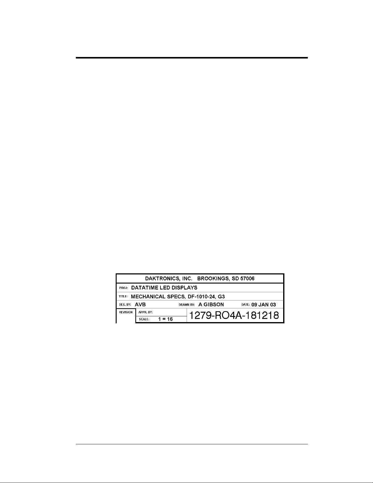
Figure 1, below, illustrates the Daktronics drawing numbering system. Daktronics
identifies individual drawings with a number (1279-RO4A-181218 in the example),
which is located in the bottom right corner of each drawing. This manual refers to
drawings by the last set of numbers in their ID as well as the letter preceding them.
The example would be Drawing A-181218.
Figure 1: Daktronics Drawing Label
Reference drawings in this manual are grouped and inserted in alphanumeric order
in the Appendix.
Listed below are a number of drawing types commonly used by Daktronics, along
with the information each is likely to provide.
System Riser Diagrams: overall system layout from control room to
display, power, and phase requirements.
Shop Drawings: fan locations, transformer locations, mounting
information, power and signal entrance points, and access method (front or
rear).
Introduction 1-1
Page 12
Schematics: power wiring, signal wiring, panelboard or power termination
panel assignments, signal termination panel assignments, and transformer
assignments.
Final Assembly: component locations, part numbers, display dimensions,
and assembly/disassembly instructions.
All references to drawing numbers, appendices, figures, or other manuals are
presented in bold typeface, as in this example: “Refer to Drawing A-181220 for the
location of the driver enclosure ”. Additionally, any drawings referenced within a
particular subsection are listed at the beginning of that subsection in the following
manner:
Reference Drawing:
Mechanical Specs, DF-1020-13, G3.....................Drawing A-181220
Daktronics identifies manuals by their engineering document (ED) number, which is
located on the cover page of the manual. For example, this manual would be referred
to as ED-13750.
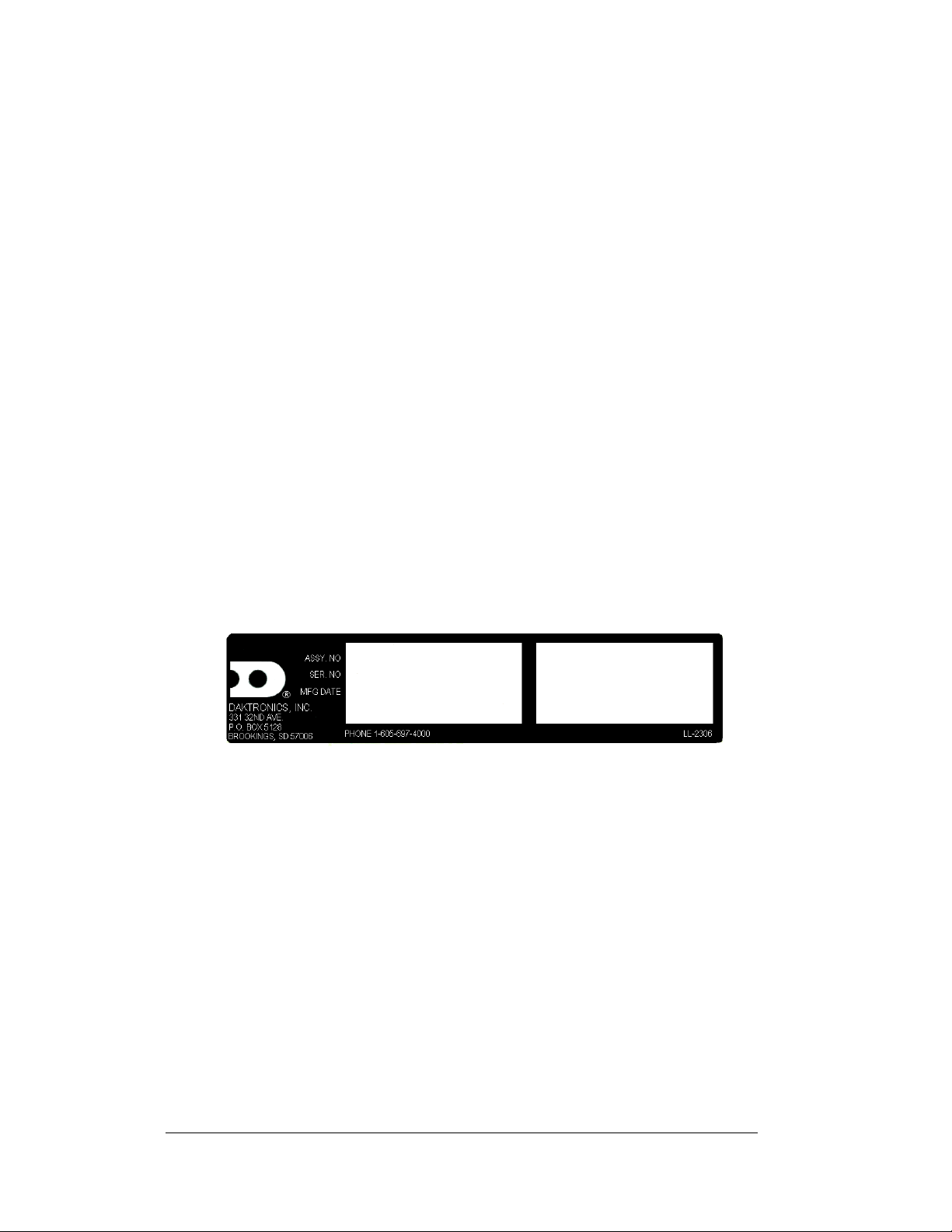
The serial and model numbers of a Daktronics display can be found on the ID label
on the display. The label will be similar to the one shown in Figure 2. When calling
Daktronics Customer Service, please have this information available to ensure that
your request is serviced as quickly as possible. For future reference, note your
display model number, serial number, and installation date on the front page of this
manual.
Figure 2: Display Identification Label
Daktronics displays are built for long life and require little maintenance. However,
from time to time, certain display components will have to be replaced. The
Replacement Parts List in Section 4 provides the names and part numbers of
components that may require replacement during the life of this display.
Following the Replacement Parts List is an explanation of Daktronics exchange and
replacement programs. Refer to these instructions if you must replace or repair any
display component.
1.2 Daktronics Nomenclature
To fully understand some Daktronics drawings, such as schematics, it is necessary to
know how various components are labeled in those drawings. You will find this
information useful when trying to communicate maintenance or troubleshooting
efforts.
1-2 Introduction
Page 13

The label “A” on a drawing item typically denotes an assembly. An assembly can be
a single circuit board or a collection of components that function together, usually
mounted on a single plate or in a single enclosure.
In addition, the following labeling formats might be found on various Daktronics
drawings:
“TB _ _” denotes a termination block for power or signal cable.
“E _ _” denotes a grounding point.
“J _ _” denotes a power or signal jack.
“P _ _” denotes a power or signal plug for the opposite jack.
Finally, Daktronics part numbers are commonly found on drawings. Those part
numbers can be used when requesting replacement parts from Daktronics Customer
Service. Take note of the following part number formats. (Not all possible formats
are listed here.)
“0P- _ _ _ _- _ _ _ _” denotes an individual circuit board, such as a driver
board.
“0A-_ _ _ _ - _ _ _ _” denotes an assembly, such as a circuit board and the
plate or bracket to which it is mounted. A collection of circuit boards
working as a single unit may also carry an assembly label.
“W- _ _ _ _ ” denotes a wire or cable. Cables may also carry the assembly
numbering format in certain circumstances. This is especially true for
ribbon cables.
“T- _ _ _ _ ” denotes a transformer.
“PR- _ _ _ _ _ - _” denotes a specially ordered part.
“M- _ _ _ ” denotes a metal part, and “0M-_ _ _ _ _ _” typically denotes a
fabricated metal assembly.
1.3 Manual Overview
This manual details outdoor LED numeric displays. It is divided into the following
sections:
Section 1: Contains an overview of the DataMaster Series, product safety
information, and labeling and numbering descriptions.
Section 2: Lists Gas Price display drawings with mechanical and electrical
information and contains a table detailing the mechanical
specifications, circuit specifications and power requirements for
each model.
Section 3: Contains information needed to perform the mechanical and
electrical installation for each model.
Section 4: Contains service and troubleshooting information.
Section 5: Contains an overview of the DataMaster controller, with a
description of the types of control systems and instructions for
DM-100 setup.
Introduction 1-3
Page 14
Section 6: Provides operating instructions for Gas Price displays.
Section 7: POS Interface Installation and Operation
Appendix: Contains all drawings referenced in this manual, quick-start
guides, and a list of frequently asked questions.
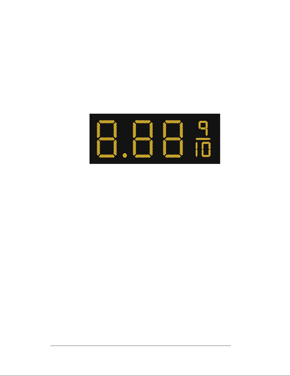
1.4 Product Overview
DataMaster Gasoline Price displays are part of a family of Daktronics products
designed for easy installation, readability, and reliability. Microprocessor control
assures consistent operation and accuracy. The Gas Price display is illustrated in
Figure 3 below.
The DataMaster Series includes:
The Gasoline Price displays are available in two styles, a full-cabinet model
designed for standalone use (DF-1020), and a front-insertion, or “drop-in”, model
designed for installation in an existing or custom sign (DF-1021).
DataMaster displays use light emitting diodes to illuminate their numeric digits.
(Light emitting diodes, or LEDs, are tiny, solid-state components that use a
semiconductor to transform electrical current into light; they are high-intensity, lowenergy lighting units.)
The displays feature highly visible PanaView
(The front-insertion Gas Price model is available with 13", 18" and 24" digits.) All
DataMaster displays are configured with red or amber LEDs.
Because of their LED technology, the displays consume little power, some barely
more than a household lamp. Power usage for individual displays in this series is a
maximum 300 W. All models have a 120 V power requirement.
Figure 3: Gasoline Price Display
Gasoline Price Displays: gas price signs with three standard digits,
decimal, and
9
Rate Displays: two- or four-digit signs, typically used to display
hotel/motel room rates or commodity prices.
Time & Temperature Displays: Automatic time & temp signs capable of
displaying temperatures in Fahrenheit or Celsius (three digits, degree
symbol, and F or C character) and 12- or 24-hour time.
/
fraction.
10
®
digits 13", 18", 24", 36" and 48" tall.
1-4 Introduction
Page 15

DataMaster cabinets, specially developed for outdoor use, are constructed of heavygauge aluminum. Digit faceplates are black, and they are set directly into the surface
of the display. Mounting weights and dimensions for each model are listed in
Section 2 of this manual.
The DataMaster outdoor LED displays have been designed for use with a
DataMaster
an insert) for display control, and the DataMaster displays themselves operate
without modification on All Sport
provides complete operating instructions.
™
100 hand-held controller. The device uses a keyboard overlay (called
1.5 Model Names
Daktronics displays, video screens, and scoreboards are differentiated by their model
numbers. The displays described in this manual all carry the two-letter prefix, DF-,
which indicates that they are DataMaster models. The letter D indicates that they are
numeric displays; the letter F indicates LED technology.
In the outdoor LED display series, typically the first set of numbers following the
prefix identifies the series or product line, while the second set of numbers refers to
digit height. A final letter denotes digit color. With Model DF-1020-13-A, for
example, 1020 identifies the Gas Price full-cabinet line, and 13 signifies that the
display’s primary digits are a nominal 13" tall. In the example, the letter A signifies
that the digits are amber, while R would indicate red LED digits.
Another designation often used with the Model DF-1021 Gas Price display is an M
or an S; those letters indicate that the display is either a master or a slave unit.
®
5000 signal protocol. Section 6 of this manual
1.6 Product Safety Approval
Daktronics outdoor displays are ETL listed and tested to CSA standards for outdoor
use. Contact Daktronics with any questions regarding the testing procedures.
Introduction 1-5
Page 16

Page 17
Section 2: Gasoline Price Display
Specifications
2.1 Mechanical Specifications Drawings
Use the following table to determine the mechanical specifications for your display.
The drawings are listed below by model number; they have been inserted in the
Appendix in alphanumeric order by drawing number.
Model Drawing Title Drawing Number
Full-Cabinet Displays (DF-1020 Series)
DF-1020-13 Mechanical Specs, DF-1020-13, G3 Drawing A-181220
DF-1020-18 Mechanical Specs, DF-1020-18, G3 Drawing A-181224
DF-1020-24 Mechanical Specs, DF-1020-24, G3 Drawing A-181234
DF-1020-36 Mechanical Specs, DF-1020-36, G3 Drawing A-165742
DF-1020-48 Mechanical Specifications,
DF-1020-48, G3
Front-Insertion/Drop-In Displays (DF-1021 Series)
DF-1021-13 Mechanical Specs, DF-1021-13, G3 Drawing A-185176
DF-1021-18 Mechanical Specs, DF-1021-18, G3 Drawing A-185203
DF-1021-24 Mechanical Specs, DF-1021-24, G3 Drawing A-185205
2.2 Electrical Specification Drawings
Use the following table to determine the electrical specifications for your display.
The drawings are listed below by model number; they have been inserted in the
Appendix in alphanumeric order by drawing number.
Drawing A-181672
Gasoline Price
Display Specifications
2-1
Page 18
Model Drawing Title Drawing Number
Full-Cabinet Displays (DF-1020 Series)
DF-1020-13 Electrical Specs, DF-1020-13, G3 Drawing A-181222
DF-1020-18
DF-1020-24
DF-1020-36
DF-1020-48
Electrical Specs, DF-1020-18, G3 Drawing A-181233
Electrical Specs, DF-1020-24, G3 Drawing A-181235
Electrical Specs, DF-1020-36, G3 Drawing A-165743
Electrical Specs, DF-1020-48, G3 Drawing A-181673
Front-Insertion/Drop-In Displays (DF-1021 Series)
DF-1021-13 Electrical Specs, DF-1021-13, G3 Drawing A-185177
DF-1021-18
DF-1021-24
Electrical Specs, DF-1021-18, G3 Drawing A-185204
Electrical Specs, DF-1021-24, G3 Drawing A-185206
2-2
Gasoline Price
Display Specifications
Page 19

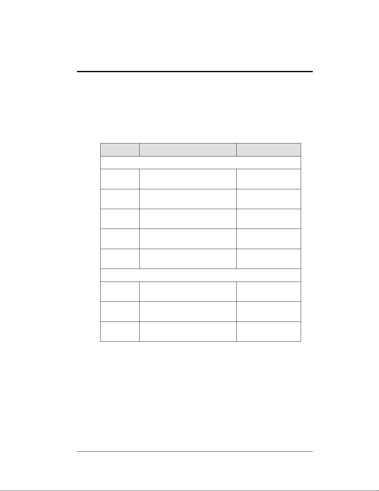
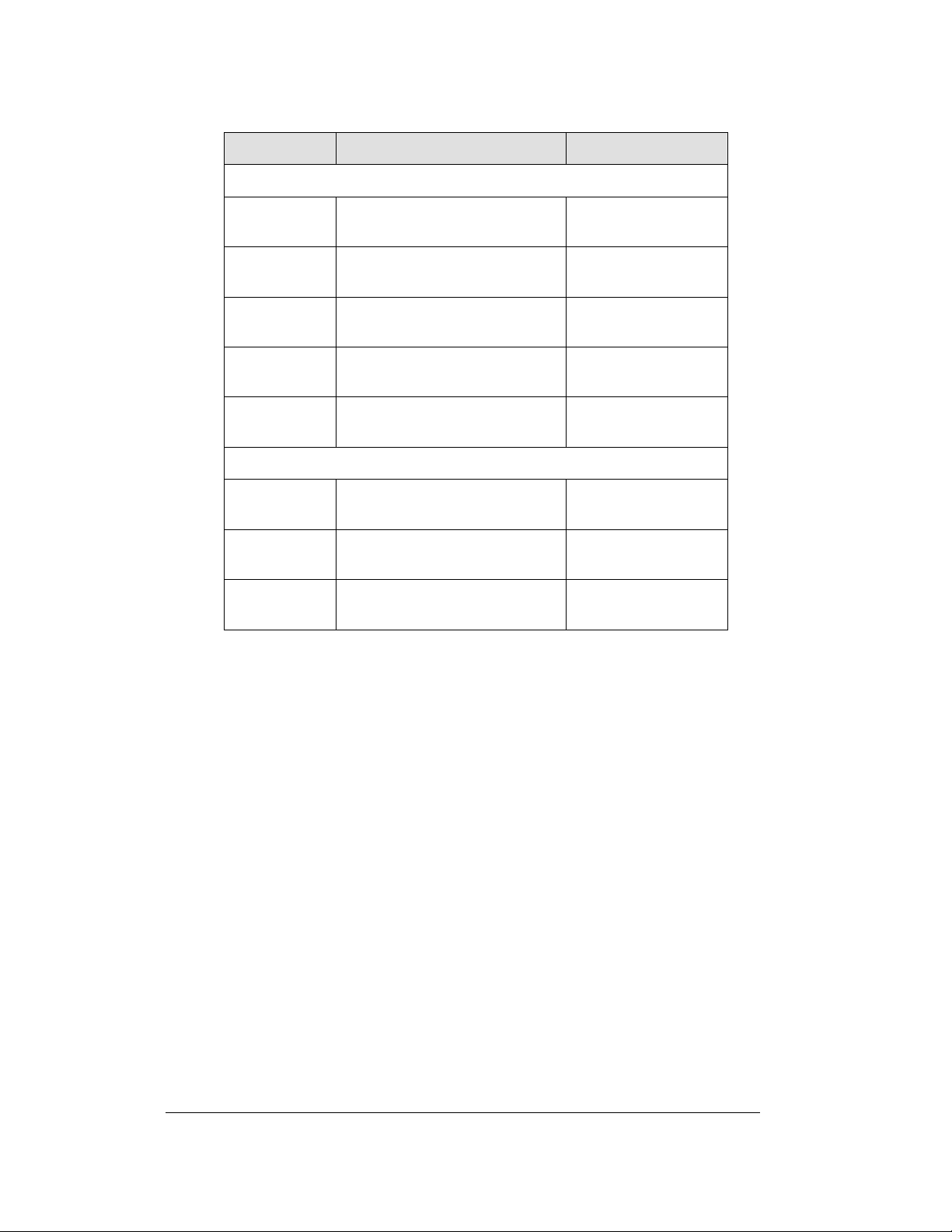
2.3 Specifications
The table below shows all of the mechanical specifications, circuit specifications, and
maximum power requirements for each model in this series. Models are listed in
alphanumeric order by digit size.
DataMaster Gasoline Price Displays
Weight
Model Dimensions
Uncrated
Crated
Digit
Size/Color
Maximum
Wattage
Circuit
DF-1020-13-A
DF-1020-13-R
DF-1020-18-A
DF-1020-18-R
DF-1020-24-A
DF-1020-24-R
DF-1020-36-A
DF-1020-36-R
DF-1020-48-A
DF-1020-48-R
H1’-6", W4’-0", D6"
(457 mm, 1219 mm,
152 mm)
H2’-0", W5’-0", D6"
(610 mm, 1524 mm,
152 mm)
H2’-6", W6’-6", D6"
(762 mm, 1981 mm,
152 mm)
H3’-6", W8’-6", D8"
(1067 mm, 2591
mm, 203 mm)
H4’-6", W11’-0", D8"
(1372 mm, 3353
mm, 203 mm)
36 lb (16 kg)
58 lb (26 kg)
60 lb (27 kg)
96 lb (44 kg)
90 lb (41 kg)
144 lb (65 kg)
160 lb (73 kg)
256 lb (116 kg)
280 lb
(127 kg)
448 lb (203 kg)
13"
(330 mm)
Amber, red
18"
(457 mm)
Amber, red
24"
(610 mm)
Amber, red
36"
(914 mm)
Amber, red
48"
(1219 mm)
Amber, red
150 W
150 W
150 W
300 W
300 W
120 V AC
1.3 A
120 V AC
1.3 A
120 V AC
1.3 A
120 V AC
2.5 A
120 V AC
2.5 A
Gasoline Price
Display Specifications
2-3
Page 20

Model Dimensions
DF-1021-13-A
DF-1021-13-R
DF-1021-18-A
DF-1021-18-R
DF-1021-24-A
DF-1021-24-R
H1’-6", W4’-0", D6"
(457 mm, 1219
mm, 152 mm)
H2’-0", W5’-0", D6"
(610 mm, 1524
mm, 152 mm)
H2’-6", W6’-0", D6"
(762 mm, 1829
mm, 152 mm)
Weight
Uncrated
Crated
36 lb (16 kg)
58 lb (26 kg)
60 lb (27 kg)
96 lb (44 kg)
90 lb (41 kg)
144 lb (65 kg)
Digit
Size/Colo
r
13"
(330 mm)
Amber, red
18"
(457 mm)
Amber, red
24"
(610 mm)
Amber, red
Maximum
Wattage
150 W
150 W
150 W
Circuit
120 V AC
1.3 A
120 V AC
1.3 A
120 V AC
1.3 A
2-4
Gasoline Price
Display Specifications
Page 21

Section 3: Mechanical and Electrical
Installation
Mechanical installation typically consists of installing concrete footings and steel beams and
mounting the display and any accompanying panels to the beams.
Electrical installation consists of the following processes:
Providing power and ground to a disconnect near the display.
Routing power and ground from the main disconnect to the display driver/power
enclosure.
Connecting the display ground to a grounding electrode at the sign location.
Routing the control signal cable from the control location to the sign location.
3.1 Mechanical Installation
Reference Drawings:
Mounting Method, Flag Style, One Pole......................Drawing A-166139
Mounting Method, Single Line on One Pole................Drawing A-166142
While DataMaster outdoor digit displays are designed for wall or pole mounting, every
installation will be different. Actual site demands will dictate the appropriate mounting
method. Most DataMaster models have fully finished exteriors, for example, but other
models are designed to be inserted into an existing sign cabinet and require a custom
installation.
The engineering drawings referenced above detail a number of mounting methods,
from a single display on a single column support to multiple displays stacked above
one another in a two-pole installation. The drawings include welding and hardware
notes that will be applicable for most installations.
Note: The drawings suggest mounting methods and are not to be considered as
specifications for construction. The actual mounting hardware and structural
design must be specified by a qualified engineer.
Lifting the Display
Model DF-1020 displays are shipped equipped with 3/8" eyebolts that are used for
lifting and positioning the modules. Eyebolts are located along the top outer edges of
the cabinet. Model DF-1021 drop-in displays are not so equipped.
Mechanical and 3-1
Electrical Installation
Page 22
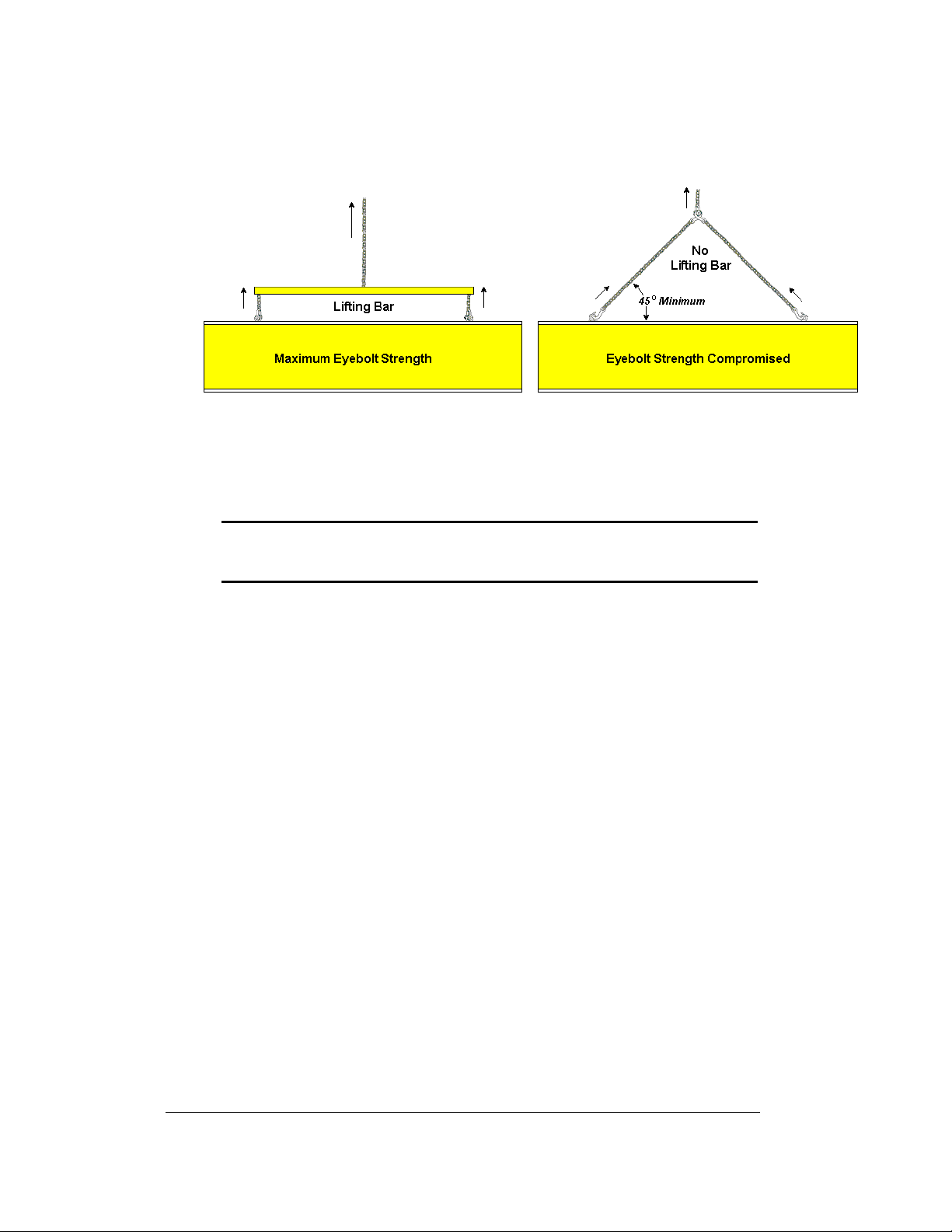
Daktronics strongly recommends using a spreader bar, or lifting bar, to lift the
display. Using a spreader bar ensures that the force on the eyebolts is straight up,
minimizing lifting stress. Figure 4, below, illustrates two lifting methods.
Figure 4: Lifting the Display
The illustration shows both the preferred method (left example) and an alternative
method (right example) for lifting a display. Be sure to use every lifting point
provided.
Note: Daktronics assumes no liability for display damage or injury
resulting from incorrect setup or incorrect lifting methods.
Eyebolts are intended for lifting during installation o nly. Do not attempt to
permanently support the display by the eyebolts.
In installations in which an ad panel or some other display section may be added to
the base display, the lower section is installed first and secured to the support beams,
and then the upper section is placed atop or above the lower sign section and
attached to the beams. There may be cables extending from the top of the lower
section. Guide these cables into the hole in the bottom of the upper section for later
connection.
Installers may remove the lift eyebolts once the display is in place. On models with
13", 18" or 24" digits, thread
digits, install
1
/2"-13 bolts in the holes.
3
/8"-13 bolts into the holes. On models with 36" or 48"
3.2 Electrical installation
Reference Drawing:
Quick Install, DF-1020 Gas Price Displays................. Drawing A-189768
Drawing A-189768 provides detailed instructions for power and signal connections
for Gas Price displays, including hookup of the light sensor and connections
between host and client displays. Refer to this drawing before undertaking any part
of the electrical installation.
3-2
Mechanical and
Electrical Installation
Page 23

Note: Only qualified individuals should perform power routing and termination
to the display. It is the responsibility of the electrical contractor to ensure that
all electrical work meets or exceeds local and national codes.
Power
Reference Drawings:
Schematic; Multipurpose 4 Col. LED Drvr.............Drawing A-165028
Schematic; Gen III Outdoor LED,
8 Column Drvr.................................................Drawing A-177935
Schematic; 16 Col Multipurpose LED Drvr............Drawing A-179599
Daktronics DataMaster displays have been designed for easy access to components,
and the power and control signal hookup has been simplified. Front panels are
removable or hinged to allow access to the digits, cabling, and other electronic
components.
Correct power installation is imperative for proper display operation. The
subsections that follow give details of display power installation. Only qualified
individuals should attempt to complete the electrical installation; untrained personnel
should not attempt to install these displays or any of the electrical components.
Improper installation could result in serious damage to the equipment and could be
hazardous to personnel.
The DataMaster outdoor displays require a dedicated, 120 V circuit for incoming
power. The display itself has no breakers or fuses.
WARNING: It is critical that the display circuit be fused at 15 A, and that all
conductors used must be designed to pass a 15 A current in normal operation.
Failure to meet wiring and overcurrent protection device requirements is a
violation of the National Electrical Code
®
and will void the display warranty.
Refer to the DataMaster display schematics listed above and to the chart in Section 2
to determine circuit specifications and maximum power requirements for the models
described in this manual.
Grounding
Reference Drawings:
Schematic; Multipurpose 4 Col. LED Drvr.............Drawing A-165028
Schematic; 16 Col Multipurpose LED Drvr............Drawing A-179599
Enclosed Driver, 4 Column Reference..................Drawing A-184918
Schematic; Gen III Outdoor LED,
8 Column Drvr.................................................Drawing A-177935
Displays MUST be grounded according to the provisions outlined in Article 250
of the National Electrical Code and according to the specifications in this
manual. Daktronics recommends a resistance-to-ground of 10 ohms or less.
Mechanical and 3-3
Electrical Installation
Page 24

The contractor performing the electrical installation can verify ground
resistance. Technicians from Daktronics Sales and Service offices can also
provide this service.
The display system must be connected to an earth electrode installed at the display.
Proper grounding is necessary for reliable equipment operation. It also protects the
equipment from damaging electrical disturbances and lightning. The display must
be properly grounded, or the warranty will be void. Refer to the schematics,
Drawings A-165028, A-177935, and A-179599, or the driver reference, Drawing
A-184918, for information on where to connect the grounding wire. Connection at
the driver enclosure terminal block is illustrated at the bottom of Drawing 184918.
The material for an earth-ground electrode differs from region to region and may
vary according to conditions present at the site. Consult the National Electrical Code
and any local electrical codes that may apply. The support structure of the display
cannot be used as an earth-ground electrode. The support is generally embedded in
concrete, and if it is in earth, the steel is usually primed or it corrodes, making it a
poor ground in either case.
Power Installation
There are two considerations for power installation: installation with ground and
neutral conductors provided, and installation with only a neutral conductor provided.
These two power installations differ slightly, as described in the following
paragraphs:
Installation with Ground and Neutral Conductors Provided
For this type of installation, the power circuit must contain an isolated earth-ground
conductor. Under this circumstance, do not connect neutral to ground at the
disconnect or at the display. This would violate electrical codes and void the
warranty. Use a disconnect so that all hot lines and neutral can be disconnected. The
National Electrical Code requires the use of a lockable power disconnect within
sight of or at the display.
Installation with Only a Neutral Conductor Provided
Installations where no grounding conductor is provided must comply with Article
250-32 of the National Electrical Code. If the installation in question meets all of the
requirements of Article 250-32, the following guidelines must be observed:
+ Connect the grounding electrode cable at the local disconnect, never at the
display driver/power enclosure.
+ Use a disconnect that opens all of the ungrounded phase conductors.
3-4
Mechanical and
Electrical Installation
Page 25
3.3 Power and Signal Connection
Reference Drawings
Schematic; Multipurpose 4 Col. LED Drvr...................Drawing A-165028
Enclosed Driver, 4 Column Reference ........................Drawing A-184918
4 Column MASC LED Driver Specifications................Drawing A-166216
Quick Install, DF-1020 Gas Price Displays..................Drawing A-189768
Schematic; Gen III Outdoor LED, 8 Column Drvr........Drawing A-177935
Schematic; 16 Col Multipurpose LED Drvr..................Drawing A-179599
8 Column MASC LED Driver Specifications................Drawing A-167237
16 Col. MASC Driver Specification..............................Drawing A-184475
Route power and signal cables into the display from the side or rear. There are
knockouts for
and on the back panels. All power and signal wiring terminates at the driver
enclosure.
Refer to Drawing A-189768 for a complete review of power and signal connections
for Gasoline Price displays. Drawings A-184918, A-167237 and A-184475 illustrate
and provide connection specifications for drivers used in DataMaster Gas Price
displays. The schematics listed above detail both the wiring in the enclosure and
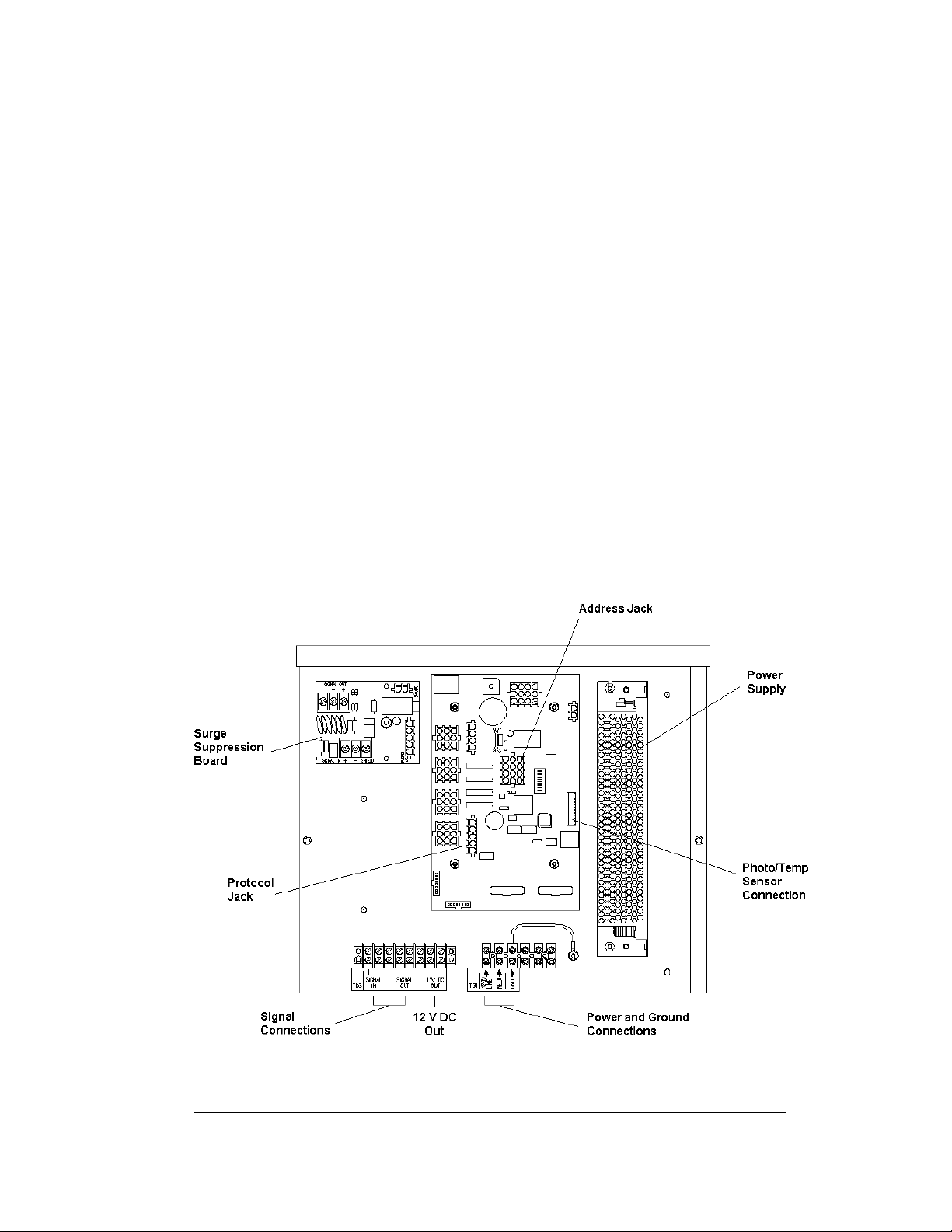
external connections to the display. Power and signal connections, illustrated in
Figure 5 below, are similar for all three drivers.
1
/2" and 3/4" conduit fittings on the sides of all DataMaster cabinets
Figure 5: DataMaster Driver Enclosure with 4-Column Driver
Mechanical and 3-5
Electrical Installation
Page 26

To gain access to the driver enclosure, open the access door and remove the cover
from the enclosure. Refer to the electrical specifications drawings for the access
location for your sign.
Connect the power and signal cables at the appropriate locations on the driver
enclosure panel, as shown in Drawing A-184918.
The power feeder circuit connects directly to a terminal block in the driver
enclosure. The block is located in the bottom center of both types of driver
enclosure. Refer to the driver illustrations and the schematics, Drawings A-165028,
A-177935 and A-179599, for wiring details.
Route signal cabling to the terminal block on the lower left edge of the enclosure
(see Figure 5). The connections are labeled to permit easy installation. (In the 16column enclosure, the signal block is at bottom center.) For signal cable, Daktronics
recommends 2-pair shielded cable, 22 AWG (Daktronics part number W-1234).
Host/Client and Master/Slave Definitions and Address
Settings
Reference Drawings:
Host/Client and Master/Slave Definitions ............. Drawing A-168376
4 Column MASC LED Driver Specifications......... Drawing A-166216
8 Column MASC LED Driver Specifications......... Drawing A-167237
16 Col. MASC Driver Specifications.....................Drawing A-184475
One driver at each sign installation is designated as the “host driver”. This driver
receives its signal directly from the controller on the Signal In terminals, and it is the
only driver that is connected to the light/temp sensor. The Sign al Out terminals are
used to connect to “client drivers”.
Select the host driver by inserting the Protocol 4 plug into the 5-pin protocol jack
(J20.) For protocol jack location, refer to the driver specifications drawings listed
above.
The 12 V DC terminals connected to the host driver (see “Signal Connections” in
Figure 5) run to the controller junction box. This output is used to power the
DataMaster 100 controller.
All other drivers in the display system are client drivers. These drivers receive signal
from the host driver on the Signal In terminals and can re-drive this signal to other
“client drivers” on the Signal Out terminals.
Some multiple-module signs use “slave displays”. These displays do not contain a
driver and may use either the client or host digit outputs. Refer to Drawing A-
168376 for an illustration of the client/host driver and master/slave display setups.
The address of each driver is set using the address jack (J19), and the address setting
is based on that driver's position in the sign or display system. If a single-line sign is
3-6
Mechanical and
Electrical Installation
Page 27
used, the address will typically be address “1”. This is the default addr ess plug that is
shipped with each display. In a multiple-module display, the address plug determines
which line of information is shown on the drivers' digits. The address plug for each
line is included in the address plug kit, if applicable.
3.4 Light Sensor Installation
Reference Drawing:
Light Sensor Installation, G3........................................Drawing A-183775
Displays in the DataMaster series use a light sensor to regulate sign dimming
functions. (Dimming involves decreasing overall display intensity, both for better
display viewing and to prolong LED life. The brightness level should be highest
during the day to compete with daylight, and lower at night.) Use Drawing A-
183775 and the following instructions to install the light sens or in your DataMaster
Gasoline Price display. If the sign or sign system has more than one display, install
the light sensor in the host display only.
1. Remove the screws on the front
of the display and open the
hinged access door.
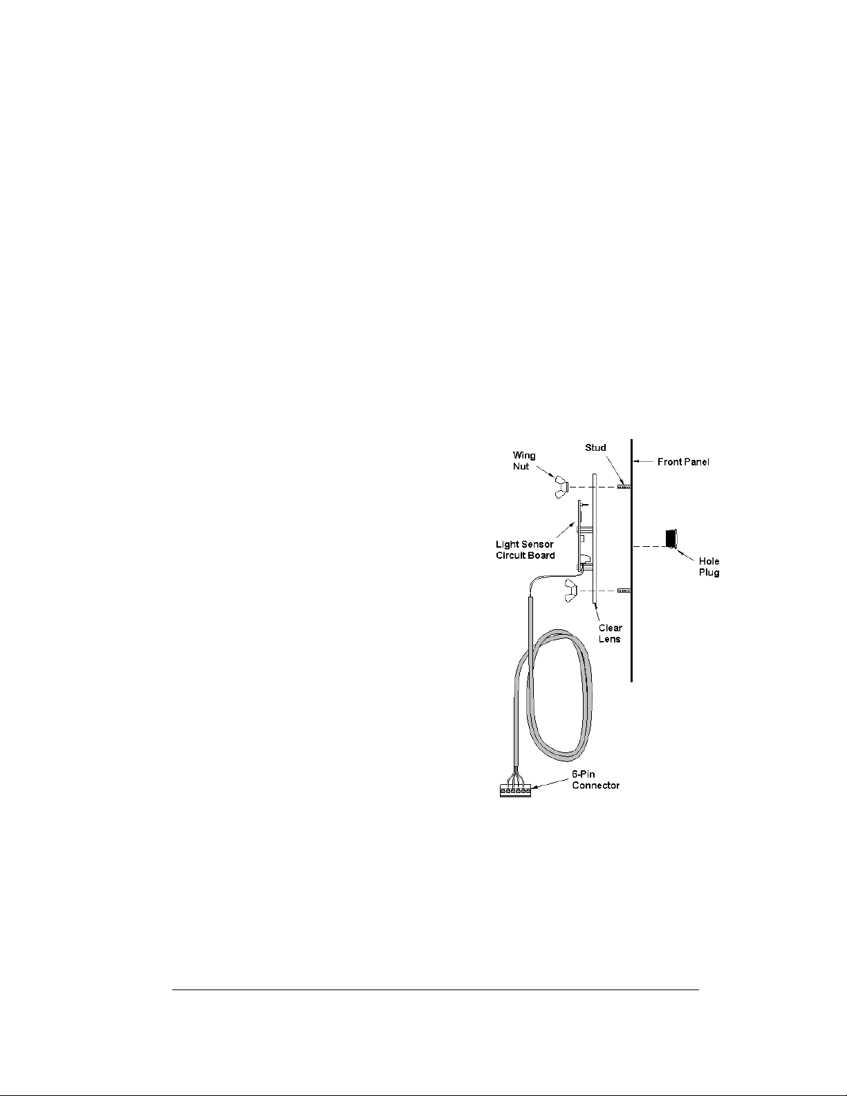
2. Locate and remove the
plastic plug from front panel of
the display, as shown in Figure
6. The location of the plug varies
by model. Refer to the
mechanical specifications
drawings for model-specific
information.
3. There are two 6-32 studs above
and below the plughole. Position
the internal light sensor assembly
on the studs, with the clear lens
toward the front of the cabinet
and the cable at the bottom.
Secure the sensor with the plastic
wing nuts provided with the
assembly kit.
4. Route the signal cable to the driver and insert the 6-postion plug into the
mating jack on the driver, TB1.
5. Close the hinged access doors and replace the screws.
5
/8"
Figure 6: Internal Light Sensor
Mechanical and 3-7
Electrical Installation
Page 28

Page 29
Section 4: Display Maintenance
and Troubleshooting
IMPORTANT NOTES:
1. Disconnect power before doing any repair or maintenance
work on the display!
2. Allow only qualified service personnel access to internal
display electronics.
3. Disconnect power when not using the display.
4.1 Cabinet Specifications
Cabinets for the Daktronics outdoor LED digit displays are constructed of heavygauge aluminum. Exact dimensions and weights for each model are listed in the
chart in Section 2. Hinged panels for servicing digits and indicators and for
component access are detailed in each model's mechanical specifications drawing.
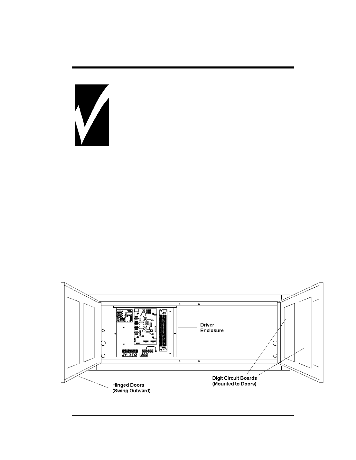
4.2 Component Location and Access
For the front-access modules in this series, all internal electronic components and
digits can be reached by opening one of the hinged access doors on the front of the
display. Each door swings outward when the two screws on the display face panel
are removed, as shown in Figure 7. For front and opened views of the displays, refer
to your model's electrical and mechanical specifications drawings, listed in Sections
2.1 and 2.2.
Figure 7: DataTime Time and Temp Display with Door Panels Open
Maintenance and 4-1
Troubleshooting
Page 30
Component placement varies slightly with each DataMaster model; consult the
model-specific mechanical drawing to determine the layout for your display.
Note: Disconnect power before servicing the display! Disconnect power, too,
when the display is not in use. Prolonged power-on may shorten the life of some
electronic components.
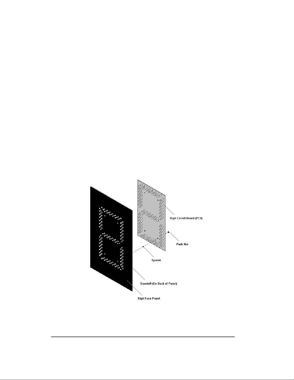
Replacing a Digit
The digit circuit board, the platform for the LEDs, is mounted to the back of the digit
panel. Do not attempt to remove individual LEDs. In the case of a malfunctioning
board, replace the entire digit panel. Refer to Figure 8 below.
To remove a display digit, follow these steps:
1. Open the digit panel as described in the preceding section.
2. Disconnect the power/signal connector from the back of the digit. Release
the connector by squeezing together the locking tabs as you pull the
connector free.
3. The digits are secured to the inside of the panel with fixed machine screws,
spacers, and push nuts. Remove the nuts and lift the digit off the standoff
screws. (The push nuts can be removed in several ways, but Daktronics
recommends using a
9
/32" nut driver.)
Figure 8: Digit Assembly
4-2
Maintenance and
Troubleshooting
Page 31

4. Position a new digit over the screws and tighten the nuts.
5. Reconnect the power/signal connector. Note: This is a keyed connector, it
6. Close and secure the digit panel and test the display.
Replacing a Digit Segment
When a digit malfunctions, in most cases it is
necessary to replace the entire digit circuit board.
Some larger digits (24", 36", 48"), however, may
be constructed in segments, as shown in Figure
9 and it may be possible to make repairs by
removing only the defective segment. As with
smaller digits, the digit segment circuit boards
are mounted to the back of the digit panel. Do
not attempt to remove individual LEDs.
To remove a digit segment, follow these steps:
1. Open the digit panel as described
2. Disconnect the 2-pin power/signal
3. The individual segments are secured to the inside of the panel with fixed
4. Position a new segment over the screws and tighten the nuts.
5. Reconnect the power/signal connector. Note: This is a keyed connector it
6. Close and secure the digit panel and test the display.
Replace a malfunctioning colon, decimal, or indicator assembly in the same manner.
will attach in one way only. Do not attempt to force the connection!
above.
connector from the back of the
individual segment. Release the
connector by squeezing together the
locking tabs as you pull the connector
free.
machine screws, spacers, and push nuts. Remove the nuts and lift the
segment off the standoff screws.
will attach in one way only. Do not attempt to force the connection!
Figure 9: Segmented Digit Panel
(Rear View)
Replacing a Driver
Drivers are typically mounted inside the display and immediately behind a digit, but
location and mounting varies by model. Refer to the component locations drawings
in Section 2 for the location of your driver. All displays in this manual are frontaccessible.
Each driver is enclosed with a power supply and signal terminal block. Before a
failed driver can be reached, the enclosure must be accessed. Follow these steps:
1. Open the digit panel or display face panel as described in Section 4.2.
2. Remove the cover from the driver enclosure.
Maintenance and 4-3
Troubleshooting
Page 32

3. Disconnect all connectors from the driver. Release each connector by
squeezing together the locking tabs as you pull the connector free. Note:
When reconnecting, remember that these are keyed connectors and
will attach in one way only. Do not attempt to force the connections.
4. Remove the screws, nuts, or wing nuts securing the driver to the inside of
the enclosure.
5. Carefully lift the driver from the display and place it on a clean, flat surface.
6. Follow steps 1 through 5 in reverse order to attach a new driver.
4.3 Schematics
Reference Drawings:
Schematic; Multipurpose 4 Col. LED Drvr................... Drawing A-165028
Schematic; Gen III Outdoor LED, 8 Column Drvr ....... Drawing A-177935
Schematic; 16 Col Multipurpose LED Drvr.................. Drawing A-179599
Drawings A-165028, A-177935, and A-179599 are the schematic diagrams for the
4-, 8- and 16-column drivers used in the DataMaster Gas Price displays. The
schematics include power and signal inputs and all wiring for the models described
in this manual.
4.4 LED Drivers
Reference Drawings:
4 Column MASC LED Driver Specifications......... Drawing A-166216
8 Column MASC Driver Specifications................. Drawing A-167237
16 Col. MASC Driver Specification.......................Drawing A-184475
In the display, the LED drivers perform the task of switching digits on and off. Refer
to Drawings A-166216 or A-184475 for a complete listing of driver connector
functions and wiring pin numbers.
DataMaster Gas Price displays may use 4-, 8-, or 16-column drivers, depending on
the model and size of digits. Each 16-column driver has 20 or more connectors
providing power and signal inputs to the circuit, and outputs to the digits and
indicators. The following table describes connector functions for a 16-column driver.
(Major functions are the same on 4- and 8-column drivers.)
Connector No. Function
J1 – 16 Outputs to digits
J17 Power and signal input
16-Column LED Driver
J18 Relay
J19 Address
4-4
Maintenance and
Troubleshooting
Page 33

Connector No. Function
16-Column LED Driver
J20 Protocol
J21-22 ISP
J23 12 V DC out
J24 Modem
J28 Switch inputs
TB1 CAN (photo/temp sensor)
Output connectors 1 through 16 each have nine pins. Pin 7 provides power (hot) to
the digit or indicators wired to that connector. The other eight pins provide switching
connections.
The display line controlled by the driver is set with jumper wires in the 12-p in
address plug inserted in jack J19. All DataMaster displays ship with a “Line 1” plug
installed.
4.5 Segmentation and Digit Designation
Reference Drawing:
Segmentation, 7 Segment Bar Digit ..............................Drawing A-38532
In each digit, certain LEDs
always go on and off together.
These groupings of LEDs are
referred to as “segments”.
Drawing A-38532 illustrates
digit segmentation. It also
details which connector pin is
wired to each digit segment
and the wiring color code used
throughout the display.
The component locations
drawings in Section 2 specify
the driver connectors
controlling the digits. Numbers
displayed in hexagons in the
upper half of each digit, as shown in Figure 10, indicate which connector or
connectors are wired to that digit. (Larger digits, like the 36" digits shown in Figure
10, are each wired to two connectors.)
Figure 10: Digit Designation
Maintenance and 4-5
Troubleshooting
Page 34

4.6 Troubleshooting
This section lists potential problems with the display, indicates possible causes, and
suggests corrective action. This list does not include every possible problem, but it
does represent some of the more common situations that may occur. (Refer to the
appropriate manual for a list of potential problems with add-on or separately
mounted message centers.
Symptom/Condition Possible Cause
Garbled display
Digit will not light
Segment will not light
Segment stays lit
Data appears in the wrong place
on the display, wrong data on a
particular line of the display
Internal driver logic malfunction
Control console malfunction
Black wire to digit broken
Poor contact at driver connection
Driver malfunction
Broken LED or connection
Driver shift register failure
Broken wire between driver and digit
Poor contact at driver connector
Driver shift register failure
Short circuit on digit
Incorrect address settings on drivers
(Refer to “Power On Self-Test” in the
following section, and consult tables to set
correct addresses.)
Some DataMaster displays have their own built-in troubleshooting mechanism.
Failures that may occur in the display driver are described using codes. In the event
a sign malfunctions, a failure code registers by displaying an “Ex” value on the first
two digits of the display. “E” simply indicates an error, and the letter “x” represents
the actual code number. Refer to the following table for a description of each failure
code and for possible solutions.
Note: The LCD screen on the DataMaster 100 controller will not show the
failure codes described in the table below. Failure codes will only be displayed
on the DataMaster sign.
4-6
Maintenance and
Troubleshooting
Page 35

Failure Code Description Possible Solution
E1 Protocol Setting Error: There is an
unsupported driver protocol
setting.
E2 Time Error: There is no valid time
stored in the driver; it may be a
failure of the real-time clock on
board or other timekeeping
device.
E3 Temp Error: There is no response
from the temp sensor or light
sensor, or general temp sensor
failure.
E4 No Message Error: This code is
shown when there are no
messages downloaded to the
display
E5 No Line Number Selected Error:
The driver for this line has a
Protocol 4 plug installed in J20,
but there is no address plug
installed in J19.
Check the value set in the protocol
plug of the driver (J20).
Set the time in the display using the
Set Time menu option on the
DataMaster 100 controller.
(DataTime Time & Temp displays
only)
Check the temp sensor location and
verify all connections. Refer to the
instruction sheet for the CAN
Temperature/Light Sensor
mounting, ED13364.
Note: The temp sensor takes
approximately 10 seconds to
initialize on power-up. The sign
will display this error until
initialization is complete.
Download a new message to the
display using the <
SEQUENCE
100 controller.
Set the line number by installing the
correct plug in J19. The Protocol 4
plug designates this driver as the
“host “. If this is not the host,
remove the Protocol 4 plug from
J20.
DISPLAY
> key on the DataMaster
Power On Self-Test:
A useful troubleshooting tool is the power on self-test the host driver performs every
time it powers up:
+ If the signal wiring between each controller is correct, the first two digits of
each driver will display “Ad” momentarily, and the first digit will then flash
three numbers indicating the decimal address that is set with the address
plug in J19. (If a client driver displays “A <number>,” followed by “P
Maintenance and 4-7
Troubleshooting
Page 36

<number>,” it is not receiving “signal in,” and is performing its own selftest.)
+ Next, the first two digits of each line will display “Lx”, where “x” is the line
number that the driver is set to control (set with address plug).
+ Finally, each line will display “1234…” according to the column number of
each of its digits. Every line should show “1” on the left-most digit, and all
digits should be numbered consecutively from left to right. If this is not the
case, either the wrong address plug is installed, or the driver or digit harness
is connected incorrectly.
If there is no address plug in the host driver, the host driver will display “E5,” and
all client drivers will continually cycle through the power on self-test.
4.7 Lightning Protection
The use of a disconnect near the display to completely cut all current-carrying lines
significantly protects the circuits against lightning damage. The National Electrical
Code also requires it. In order for this device to provide protection, the power must
be disconnected when the display is not in use. The control console should also be
disconnected from power and from the signal j-box when the system is not being
used. The same surges that may damage the display's driver can also damage the
console's circuit.
4.8 Replacement Parts
4-8
Maintenance and
Troubleshooting
Page 37

Refer to the following table for Daktronics replacement parts.
Description
Daktronics
Part No.
Light sensor, G3 0A-1279-0203
Protocol plug (Protocol 4) 0A-1279-0089
Transformer, wall pack (for DataMaster 100) T-1118
DataMaster 100 hand-held controller 0A-1196-0088
Junction box, outdoor, 9-pin D-male 0A-1196-0093
Junction box, indoor, 9-pin D, male 0A-1196-0099
Power supply, 24 V DC, 150 W A-1720
Signal surge suppression board 0P-1110-0011
Driver, 4-column MASC, LED 0P-1192-0068
Driver, 8-column MASC, LED 0P-1192-0082
Driver, 16-column, MASC, LED 0P-1192-0086
DataMaster 100 outdoor wired installation kit 0A-1279-0087
DataMaster 100 indoor wired installation kit 0A-1279-0103
Maintenance and 4-9
Troubleshooting
Page 38

Description Daktronics
Part No.
Cable, 6-conductor, 22 AWG (for radio installation) W-1210
Cable, serial, DB9 male to DB9 female W-1267
Digit, 13" red, pc board 0P-1192-0200
Digit, 13" amber, pc board 0P-1192-0214
Digit, 13" 9/10, red, pc board 0P-1192-0234
Digit, 13" 9/10, amber, pc board 0P-1192-0234
Digit, 18" 7-segment, red, pc board 0P-1192-0235
Digit, 18" 7-segment, amber, pc board 0P-1192-0216
Digit, 13" 7-segment, red, w/ faceplate 0A-1192-2223
Digit, 13" 7-segment, amber, w/ faceplate 0A-1192-2224
Digit, 18" 7-segment, red, w/ faceplate 0A-1192-2227
Digit, 18" 7-segment, amber, w/ faceplate 0A-1192-2228
Digit, 24" 9/10 red, pc board 0P-1192-0232
Digit, 24" 9/10 amber, pc board 0P-1192-0233
Digit, 24" 7-segment, red, w/ faceplate 0A-1192-2231
Digit, 24" 7-segment, amber, w/ faceplate 0A-1192-2232
Digit segment, 24" red, vert 0P-1192-0204
Digit segment, 24" red horiz 0P-1192-0205
Digit segment, 24" amber, vert 0P-1192-0218
Digit segment, 24" amber horiz 0P-1192-0219
Digit, 24" 9/10 red, w/faceplate 0P-1192-2359
Digit, 24" 9/10 amber, w/faceplate 0P-1192-2360
Digit, 36" 7-segment, red, hinged 0A-1279-0195
Digit, 36" 7-segment, amber, hinged 0A-1279-0196
Digit segment, 36" red, vert 0P-1192-0208
Digit segment, 36" red horiz 0P-1192-0209
Digit segment, 36" amber, vert 0P-1192-0222
Digit segment, 36" amber horiz 0P-1192-0223
4-10
Maintenance and
Troubleshooting
Page 39

Description Daktronics
Digit, 48" 7-segment, red, hinged 0A-1279-0181
Digit, 48" 7-segment, amber, hinged 0A-1279-0182
Digit segment, 48" red, vert 0P-1192-0212
Digit segment, 48" red horiz 0P-1192-0213
Digit segment, 48" amber, vert 0P-1192-0226
Digit segment, 48" amber horiz 0P-1192-0227
Decimal, 13" red, pc board (used in DF-1020-13) 0P-1192-0238
Decimal, 13" amber, pc board (used in DF-1020-13) 0P-1192-0239
Part No.
Indicator, 2" red, pc board (used in 18" and 24" displays) 0P-1192-0228
Indicator, 2" amber, pc board (used in 18" and 24" displays) 0P-1192-0229
Indicator, 4" red, pc board (used in 36" and 48" displays) 0P-1192-0244
Indicator, 4" amber, pc board (used in 36" and 48" displays) 0P-1192-0245
Indicator, 4" red w/ face plate (used in 36" and 48" displays) 0A-1192-2434
Indicator, 4" amber w/ face plate (used in 36" and 48" displays) 0A-1192-2435
4.9 Daktronics Exchange and Repair and Return
Programs
To serve customers' repair and maintenance needs, Daktronics offers both an
Exchange Program and a Repair and Return Program. Daktronics' unique Exchange
Program is a quick, economical service for replacing key components in need of
repair. If a component fails, Daktronics sends the customer a replacement, and the
customer, in turn, sends the failed component to Daktronics. This not only saves
money but also decreases display downtime.
Daktronics provides these plans to ensure users get the most from their Daktronics
products, and it offers the service to qualified customers who follow the program
Maintenance and 4-11
Troubleshooting
Page 40

guidelines explained below. Please call the Help Desk – 877-605-1115 – if you have
questions regarding the Exchange Program or any other Daktronics service.
When you call the Daktronics Help Desk, a trained service technician will work with
you to solve the equipment problem. You will work together to diagnose the
problem and determine which exchange replacement part to ship. If, after you make
the exchange, the equipment still causes problems, please contact our Help Desk
immediately.
If the replacement part fixes the problem, package the defective part in the same box
and wrapping in which the replacement part arrived, fill out and attach the enclosed
UPS shipping document, and RETURN THE PART TO DAKTRONICS. In most
circumstances, you will be invoiced for the replacement part at the time it is shipped.
This bill is due when you receive it.
Daktronics expects immediate return of an exchange part if it does not solve the
problem. The company also reserves the right to refuse equipment that has been
damaged due to acts of nature or causes other than normal wear and tear.
If the defective equipment is not shipped to Daktronics within 30 working days from
the invoice date, it is assumed you are purchasing the replacement part, and you will
be invoiced for it. This second invoice represents the difference between the
exchange price and the full purchase price of the equipment. The balance is due
when you receive the second invoice. If you return the exchange equipment after 30
working days from the invoice date, you will be credited for the amount on the
second invoice, minus a restocking fee.
To avoid a restocking charge, please return the defective equipment within 30
days from the invoice date.
Daktronics also offers a Repair and Return program for items not subject to
exchange.
Return Materials Authorization: To return parts for service, contact your local
representative prior to shipment to acquire a Return Material Authorization (RMA)
number. If you have no local representative, call the Daktronics Help Desk for the
RMA. This expedites repair of your component when it arrives at Daktronics.
Packaging for Return: Package and pad the item well so that it will not be
damaged in shipment. Electronic components such as printed circuit boards should
be installed in an enclosure or placed in an antistatic bag before boxing. Please
enclose your name, address, phone number and a clear description of symptoms.
4-12
Maintenance and
Troubleshooting
Page 41

This is how to reach us:
Mail: Customer Service
Daktronics, Inc.
PO Box 5128
331 32nd Ave
Brookings SD 57006
Phone: Daktronics Help Desk: 877-605-1113 (toll free)
or 605-697-4034
Fax: 605-697-4444
E-mail: helpdesk@daktronics.com
Maintenance and 4-13
Troubleshooting
Page 42

Page 43

Section 5: DataMaster 100 Controller
This section describes the DataMaster 100 and includes the following subsections:
+ DM-100 Controller Overview identifies the control equipment, lists replacement
parts, and describes how the DM-100 operates the displays.
+ Control System Overview reviews the three main options for display control.
+ Controller Signal Connection further details the actual setup of the DM-100 when
used in an indoor location and in a base-of-sign application.
5.1 DataMaster 100 Overview
Reference Drawing:
System Riser Diagram, Control Combinations............Drawing A-164988
The DataMaster
designed to operate Daktronics LED
DataMaster
controller, 6
encased in ABS plastic, making it a
durable and convenient control option.
The console’s liquid crystal display
(LCD) guides the user through the
operation of the system.
The DataMaster 100, identified by the
series number DM-100, can be configured
to display gasoline price, motel rates, and
time and temperature data. Refer to
Drawing A-164988 for information on
possible control options and connection
procedures.
For details on configuring the DataMaster
to operate a display, refer to Section 6:
Gas Price Display Operation.
Note: When your carrier delivers your Daktronics order, open the packages
and inspect for shipping damage such as rattles and dents. See that all
equipment is included as shown on the packing slip. Immediately report any
deficiencies to Daktronics. Save all packing materials for shipping if warranty
repair or exchange is needed.
100 Series controller, shown in Figure 11, is a hand-held controller
displays. This lightweight
1
/4" high by 4 1/4" wide, is
Figure 11: DataMaster 100
Replacement Parts List
The following is a list of possible replacement parts for the DataMaster 100
controller. When re-ordering a part, be sure to use its corresponding part number.
DM-100 5-1
Controller
Page 44

Wall pack transformer T-1118
DataMaster 100 controller 0A-1196-0088
Control Insert 0G-164998
Cable, DB-9 male to DB-9 female, 10' W - 1267
Description Daktronics Part No.
Refer to Section 4.9 for details concerning the Daktronics exchange and repair
programs.
5.2 Control System Overview
All of the displays in the LED DataMaster Series have three main control options:
direct wire, radio, and data download from a junction box at the sign. Refer to the
appropriate system riser diagram, listed above, for detailed instructions on control
system setup.
This manual covers direct-wire installations only! For
systems using modem or radio communication, also
refer to the following manuals:
ED13953: DataMaster Modem Installation Manual
ED13894: DataMaster Radio Installation Manual
5-2
DM-100
Controller
Page 45

Wire Control
Reference Drawings:
Riser Diagram, Outdoor Wire Control...................Drawing A-164988
Riser Diagram, Indoor Wire Control......................Drawing A-175342
For display systems using a base-of-sign
connection, the DataMaster 100
controller, shown with a connecting cable
in Figure 12, plugs directly into an
outdoor junction box, where the operator
keys in instructions for the sign.
Typically, the j-box is mounted to the
display pedestal or column support, and
the controller connects with the box via
TIA/EIA-232 signal cable (formerly RS-
232). The controller draws its power from
the display itself. Refer to Drawings A-
175342 and A-164988 for complete
details on both indoor and outdoor directwire installations.
Signal from the junction box enters the
sign and travels to the first display driver
over 2-pair, shielded signal cable. The 22
Figure 12: DataMaster 100 Controller
with Signal Cable
AWG cable must be enclosed in conduit.
Re-driven signal travels from the driver of
the first display to the driver of the next over another line, also 22 AWG shielded
cable in conduit. The process repeats for as many displays as there are in the system.
Once instructions have been input into the display, the driver's memory retains the
data, and the controller can be unplugged. The sign will continue to operate on the
stored information.
Signal cabling is similar for systems where the DataMaster displays will be operated
remotely from a building location, except that the controller requires a wall pack
transformer. The transformer plugs into both the hand-held controller and into a 120
V AC outlet. The DataMaster controller also connects to a junction box to send
signal to the display, but the j-box will be located within the store or office. The
control location can be up to 2000 feet from the actual sign.
The operator changes the display by entering current prices, rates, and operating
instructions on the keypad of the DataMaster controller. For complete details on sig n
operation, refer to Section 6.
DM-100 5-3
Controller
Page 46

5.3 Controller Signal Connection
This section provides information on the setting up the signal connection between
the DM-100 and DataMaster Gasoline Price displays.
Reference Drawing:
System Riser Diagram; Control Combinations.....Drawing A-164988
The DataMaster displays may be controlled from a location inside a building, or
from the base of the display, depending on customer preference. Drawing A-164988
and the subsections that follow provide greater detail on both installations using
signal wire.
Wire Control from the Base of the Sign
This control option, illustrated in
Figure 13, permits operation of the
sign from the base of the display. The
controller is connected to an outdoor
junction box mounted on the display
pole, which routes the signal to the
sign through one 2-pair cable, 22
AWG. Cable is in conduit where
required.
This control option does not require
the controller to be connected to a
power outlet. In this configuration,
the DataMaster 100 uses the sign as a
power source.
To operate the DataMaster display
using this setup, connect the 9-pin to
9-pin cable from the DataMaster
controller to the 9-pin j-box mounted
on the display pole.
Figure 13: Wire Control from Base of Sign
Wire Control from a Building Location
This control option, illustrated in Figure 14, permits operation of the sign from an
indoor control location. The hand-held controller is connected to an indoor junction
box (j-box), which routes the signal to the sign through one 2-pair cable, 22 AWG.
Cable is in conduit where required.
5-4
DM-100
Controller
Page 47

To operate the DataMaster
display using this setup, connect
the 9-pin to 9-pin cable from the
DataMaster controller to the 9pin j-box, and plug the
controller's wall pack transformer
into a 120 V AC outlet.
Figure 14: Wire Control from Building Location
DM-100 5-5
Controller
Page 48

Page 49

Section 6: Gas Price Display Operation
This section covers the basic operation of the DataMaster Gasoline Price display using the
DataMaster 100 controller.
6.1 DataMaster™ Insert and Code
Reference Drawing:
Insert, LL-2551 Price/T&T Display..................................Drawing A-164998
The DataMaster 100 uses a keypad insert to program gas price information into
Daktronics LED DataMaster Gas Price displays.
Figure 15 illustrates the DM-100
insert used to control the
displays. For more details on the
insert, refer to the DataMaster
100 insert drawing, Drawing A-
164998, located in the
Appendix.
If an insert is lost or damaged, a
copy of the insert drawing
located at the end of this section
can be used until a replacement is
ordered.
To start the controller and use the
insert, refer to the display
operation information located in
this section. Read the section
carefully to fully understand the
operation instructions.
Figure 15: DataMaster 100 Insert LL-2551
6.2 Gas Price Display Operation
The DataMaster 100 controller can be configured to program gas price variances
displayed on the LED DataMaster Gas Price sign. The instructions provided in this
section discuss the functions the operator uses to control the Gas Price display.
In the unlikely event that the Gas Price display malfunctions, refer to Appendix B
for some troubleshooting actions that can be taken.
Gas Price 6-1
Display Operation
Page 50

Gas Price Display Startup
To operate the DataMaster Gas Price displays, the DataMaster 100 must first be
programmed to the gas price function. Use the <
the following table as a guide to startup procedures.
LCD Screen Action
SET FUNCTION> key on startup. Use
CURRENT FUNCTION
GAS PRICE
CHANGE FUNCTION?
PRESS SET FUNCT
SELECT FUNCTION
GAS PRICE ↓↑
The DataMaster 100 handheld controller should now be ready for use. The controller
will “remember” the last function setting, so this step should only need to be done
with a new controller, or one that is configured for different displays. To operate the
DataMaster 100, press any of the keys listed in the following gas price sections.
Plug the wall pack transformer into a 120 V AC
power outlet, and connect it to the DataMaster
100.
This display appears briefly.
This message appears next on the screen.
If “GAS PRICE” was shown on the bottom line
of the LCD during startup, do nothing. The
controller will automatically default to previous
Gas Price settings.
If a function other than “GAS PRICE” was
shown on the bottom line of the LCD during
startup, press the <
the second LCD prompt is displayed.
Press the arrow up or down keys<↑↓> until the
gas price option is shown. Press the <
key to accept.
SET FUNCTION> key while
ENTER>
Gas Price Controller Operation
The Gas Price Controller LCD display will default to showing the current display
settings on power up. The following text will be shown on the LCD.
6-2
Gas Price
Display Operation
Page 51

LCD Screen Action
LINE PRICE
1 ↓ $1.23 9/10
<EDIT> TO MODIFY
1 ↓ $1.23 9/10
The display will toggle between these two
screens.
Press the up or down arrow keys <
through the current setting for any of the lines
on the display.
Press the <
the line settings.
ENTER/EDIT> key to modify any of
↑↓> to scroll
Modifying Price Line Settings
The gas price can be modified either by pressing the <EDIT> key during operation
(see Gas Price Controller Operation) or using the <
Refer to the following key to identify the item to be edited.
L = Current line number to be edited
D.CC = Current dollars and cents value to edit
T = Current tenths of cent value to edit
LCD Screen Action
MENU> key (see Menu Items).
EDIT LINE L
$D.CC T/10 ↓
Press any of the number keys to edit the price
value for this line. Press the down arrow key <
to modify the value of the 1/10-cent data for this
line (see note below).
Press <
<
Note: The flashing asterisk on the LCD shows
the current data being edited.
Many displays do not have a changeable 1/10cent digit. Changing the tenths-cent value from 9
on these digits will make the digit appear
incorrect.
ENTER> to accept the new value or press
CLEAR> to abort the changes.
↓>
Dimming
The dimming level of the Gas Price display can be adjusted in two ways. A
temperature/light sensor, mounted near the display, can detect the level of ambient
light at the display location and dim the sign's LEDs accordingly. This function is
known as automatic dimming. When the manual dimming function is selected, the
Gas Price 6-3
Display Operation
Page 52

LEDs remain at the same level of brightness regardless of the level of light detected
at the display.
To select either of these dimming functions, or to enter the Blank Sign function,
press <
DIMMING>. The current setting is shown on the bottom line of the LCD.
LCD Screen Action
DIMMING
1) AUTOMATIC ↓
If AUTOMATIC dimming is selected, the following LCD prompt will be shown:
LCD Screen Action
SET AUTO DIMMING
MAX INTENSITY?
Press the down arrow key <↓> to toggle
through dim settings:
Automatic – The display automatically dims
based on the light detected at the display*
Manual – The display dimming level is set
manually. Once set, this value remains
regardless of the level of light detected at the
display.
Blank Sign – The display can be blanked out
without powering down. Refer to the Blank
Sign section for details.
Press the <ENTER/EDIT> key to edit the auto
dimming max intensity. This is the maximum
intensity that the display will use in full-bright
modes (during daylight hours.)
Press <
dimming maximum setting
CLEAR> to keep the current auto
6-4
Gas Price
Display Operation
Page 53

The following LCD prompt is shown for either Manual or Automatic dimming
selections:
LCD Screen Action
INTENSITY XX↓↑
ENTER TO SET
XX – Current intensity (1-16)
Max intensity - 16
LCD Screen Action
DIMMING
BLANK SIGN ↓
BLANK THE SIGN?
<ENT> YES
<CLR> NO
Press the up or down arrow key <↑↓> to
modify the current intensity of the display
(Note: The DataMaster must be connected to
the display.)
Press <
manual dimming mode is selected, this will be
the new intensity for the display. If the
automatic dimming mode is selected, the
display will illuminate in full-bright mode,
which is the maximum intensity level.
Press <ENTER> to accept this option.
The next LCD dialog will ask whether you
want to blank the screen or escape. The LCD
toggles between Yes and No. Pressing
<CLR> resumes normal operation; pressing
<ENT> actually blanks the sign.
ENTER> to accept this intensity. If the
LCD Screen Action
RESTART SIGN?
<ENT> YES
<CLR> NO
To resume normal operation from a blanked
sign, press the <DIMMING> key again. The
DM-100 will display a Restart Sign message.
Press <ENT> to restart or press <CLR> to
return to the menu without restarting the sign.
Display Sequence
Once connected to the base of the display or to the indoor j-box, press <DISPLAY
SEQUENCE
for a preview of the new sequence on the LCD.
Gas Price 6-5
Display Operation
> to display the new sequence on the display. This button will also allow
Page 54

Menu Items
Pressing the <MENU> key accesses the following settings:
1. Price Line 1
2. Price Line 2
3. Price Line 3
4. Price Line 4
5. Price Line 5
6. LED Test
7. Modem Settings
8. Display Status
9. Set Time
Use Menu items 1-5 to edit the price on each line of the display. Lines are typically
numbered top to bottom with 1 being the top of the display. For further details, refer
to Modifying Price Line Settings discussed previously in this section.
For more information about the Modem Settings submenu, refer to ED13953:
DataMaster Modem Installation Manual. For additional information about the
Display Status or the Set Time submenus, refer to ED13894: DataMaster Radio
Installation Manual.
Edit Price Line 1-5
After pressing the <MENU> key, the following LCD prompt is displayed:
LCD Screen Action
PRICE LINE 1
ENTER TO EDIT
Use Menu items 1-5 to edit the price on each line of the display. (Lines are typically
numbered top to bottom with 1 being the top of the display.) See Modifying Price
Line Settings.
6-6
Gas Price
Display Operation
Pressing the <MENU> key displays this
message.
Press <
item shown on the LCD.
Press the up or dow n arrow keys to
move to the previous or next item in
the list.
Press the <
press the <
editing) to exit the menu.
ENTER> to edit the current
MENU> key a second time or
CLEAR> key (press twice if
Page 55

LED Test
Select menu item 6, LED Test, to test the LED digits on the display.
LCD Screen Action
LED TEST
ENTER TO TEST
ENTER TO TEST
CLEAR TO EXIT
Press the <
digits between all LEDs on and all LEDs off.
Press <
sign.
Press <
ENTER> key to cycle the display
ENTER> send the test command to the
CLEAR> to exit the test mode
Gas Price 6-7
Display Operation
Page 56

Page 57

Section 7: POS Interface Installation and
Operation
A Point of Sale (POS) interface option is available with DataMaster LED Gasoline Price
Displays. Displays with this option automatically update when product prices are changed in
the POS. Displays with the POS interface option will be supplied with a POS Interface Kit
(0A-1279-0400 for Gilbarco G-Site).
BEFORE YOU START:
1. Ensure that the POS system has a price sign output port, and refer to the POS
manuals to enable and/or configure the port.
2. Locate the parts in the list below.
7.1 Hardware installation:
1. Locate the following parts:
a) POS Interface Kit containing:
i) DataMaster 100 w/POS option (0A-1196-0133)
ii) Wall mounting bracket for DM-100 (0M-200082)
iii) POS Interface Cable for Gilbarco G-Site POS: RJ45 to DB9 cable
(0A-1279-0402)
iv) POS riser diagram (drawing number 200195)
b) 10’ cable, DB9 to DB9 (W-1267)
c) Indoor junction box (0A-1196-0099) for direct wired installations
OR…
d) Radio Interface junction box (0A-1279-0161) for wireless installations.
e) Wallpack transformer (T-1118).
2. The wall mount bracket (0M-200082) provides convenient storage for the
DM-100 controller. If using the wall mount bracket for the DM-100, ensure
that there is sufficient clearance above the bracket to allow the DM-100 to
be removed from the bracket with both cables attached. Also ensure that the
POS interface cable will reach from the DM-100 location to the price sign
output of the POS. Fasten the wall mount bracket if desired. The DM-100
can be permanently attached to the wall mounting bracket by removing the
two screws in the bottom edge of the DM-100, sliding the DM-100 into the
wall mount bracket, and reinstalling the screws through the slots in the
bottom bracket flange.
3. Mount the junction box (c. or d. above). Ensure that the DB9 to DB9 cable
(W-1267) will reach from the DM-100 to the junction box.
4. Complete junction box to sign, or junction box to radio wiring as shown on
the riser diagram (drawing 200195).
5. Attach the POS interface cable to the POS price sign port. Coil any excess
cable and cable tie it out of the way.
6. Attach the DB9 to DB9 cable (W-1267) to the junction box as shown on the
riser diagram. Coil any excess cable and cable tie it out of the way.
POS Interface 7-1
Installation and Operation
Page 58

7. Plug the transformer (T-1118) into an outlet, and connect the output to the
power jack on the J-box.
8. Ensure that the DM-100 is up and running. Send a price change to the sign
to verify communications between the sign and the DM-100.
7.2 Configuring the DM-100 for Gilbarco G-Site
Interface
BEFORE YOU START:
The DM-100 function must be set to “GAS PRICE”. The current function of the
DM-100 is displayed during power up. To change to function, cycle power to the
DM-100, and press the <
1. Press the <Menu> key and use the <
SETTINGS” menu item.
SET FUNCTION> key when prompted.
↑> and <↓> keys to scroll to the “POS
POS SETTINGS
ENT TO MODIFY ↓↑
Press <ENTER>.
2. Select the POS type by using the <
“GILBARCO GSITE”.
↑> and <↓> keys to scroll to
POS INTERFACE
GILBARCO GSITE ↓↑
Press <ENTER>.
3. Each price in the Gilbarco G-Site is uniquely identified by ‘price category’.
Each price category corresponds to the price assigned to a particular
grade/service level/price level. Use the menu shown below to configure
which price category you would like displayed on each line of the display.
PRICE CATEGORY
LINE 1 : 1 ↓↑
Use the <
sign. Press <ENTER> to accept the setting. Pressing <ENTER> when the price
category displayed is <NONE> will cause the price sign to ignore POS data for this
line. (This may be useful for configuring some lines of a price sign to receive manual
price changes only).
Select a price category to be displayed on each line of the sign, and press <MENU>,
or <ESC/CLEAR> when finished. The POS interface configuration is complete.
↑> and <↓> keys to select a price category to be displayed on line 1 of the
7-2
POS Interface
Installation and Operation
Page 59

Changing Prices:
Each display line for which a price category is configured will automatically update
when the price is changed in the POS system. Attempting to manually edit prices
that are configured for POS control will cause the following screen to appear:
THIS LINE POS
CTRLD. OVERRIDE?
Press <ENTER> to manually edit the price, or <ESC/CLEAR> to cancel.
POS Interface 7-3
Installation and Operation
Page 60

Page 61

Appendix A: Reference Drawings
The Daktronics drawing number is located in the bottom right corner of the drawing. Refer to
Section 1.1 for instructions on reading the drawing number.
Drawings in this manual are referenced by their last set of digits and the letter preceding
them. Drawings in this appendix are first listed in alphanumeric order; a second grouping lists
drawings by function.
A Drawings (All Drawings)
Segmentation, 7 Segment Bar Digit.................................................................Drawing A-38532
Riser Diagram; Outdoor Wire Control............................................................Drawing A-164988
Insert, 0G-164988 Price/ T&T Display...........................................................Draw ing A-164998
Schematic; Multipurpose LED Drvr................................................................Drawing A-165028
Mechanical Specs, D-F-1020-36, G3.............................................................Drawing A-165742
Electrical Specs, D-F-1020-36, G3................................................................Drawing A-165743
Mounting Method, Flag Style, One Pole........................................................Drawing A-166139
Mounting Method, Single Line on One Pole...................................................Drawing A-166142
4 Column MASC LED Driver Specifications...................................................Drawing A-166216
8 Column MASC LED Driver Specifications...................................................Drawing A-167237
Host/Client and Master/Slave Definitions.......................................................Drawing A-168376
Riser Diagram, Indoor Wire Control...............................................................Drawing A-175342
Schematic; Gen III Outdoor LED, 8 Column Driver........................................Drawing A-177935
Schematic; 16 Col Multipurpose LED Drvr.....................................................Drawing A-179599
Mechanical Specs, DF-1020-13, G3..............................................................Drawing A-181220
Electrical Specs, DF-1020-13, G3 ................................................................. Drawing A-181222
Mechanical Specs, DF-1020-18, G3..............................................................Drawing A-181224
Electrical Specs, DF-1020-18, G3 ................................................................. Drawing A-181233
Mechanical Specs, DF-1020-24, G3..............................................................Drawing A-181234
Electrical Specs, DF-1020-24, G3 ................................................................. Drawing A-181235
Mechanical Specifications, DF-1020-48, G3..................................................Drawing A-181672
Electrical Specs, DF-1020-48, G3 ................................................................. Drawing A-181673
Light Sensor Installation ................................................................................Drawing A-183775
16 Col. MASC Driver Specification................................................................Drawing A-184475
Enclosed Driver, 4 Column Reference...........................................................Drawing A-184918
Mechanical Specs, DF-1021-13, G3..............................................................Drawing A-185176
Electrical Specs, DF-1021-13, G3 ................................................................. Drawing A-185177
Mechanical Specs, DF-1021-18, G3..............................................................Drawing A-185203
Electrical Specs, DF-1021-18, G3 ................................................................. Drawing A-185204
Mechanical Specs, DF-1021-24, G3..............................................................Drawing A-185205
Electrical Specs, DF-1021-24, G3 ................................................................. Drawing A-185206
Quick Install, DF-1020 Gas Price Displays....................................................Drawing A-189768
Reference Drawings A-1
Page 62

Page 63

Page 64

Page 65

Page 66

Page 67

Page 68

Page 69

Page 70

Page 71

DATE:REV BY:
1 06JUN02 JJS
ADDED LED LABELS
ADDED NEW NOTES
DATE:REV BY:
2 16 MAY 03 CJB
UPDATE DRIVER FOR LATEST REVISION
OF MASC DRIVER.
DATE:REV BY:
3 27 NOV 04 DMD
UPDATE DRIVER J-27 FOR CORRECT PIN OUT
DATE:REV BY:
04 01 FEB 13 RBN
CORRECTED S1 PINOUT
THE CONCEPTS EXPRESSED AND DETAILS SHOWN ON THIS
DRAWING ARE CONFIDENTIAL AND PROPRIETARY. DO NOT
REPRODUCE BY ANY MEANS WITHOUT THE EXPRESSED
WRITTEN CONSENT OF DAKTRONICS, INC.
COPYRIGHT 2013 DAKTRONICS, INC.
DAKTRONICS, INC.
AV
DRAWN: DATE:
SHEET JOB NO:REV
OUTDOOR LED SCOREBOARDS
4 COLUMN MASC LED DRIVER SPECIFICATIONS
JSPAHR 29 APR 02
P1192 R
07 A
1=2
166216
04
Page 72

Page 73

Page 74

Page 75

Page 76

Page 77

Page 78

Page 79

Page 80

Page 81

Page 82

Page 83

Page 84

Page 85

Page 86

Page 87

Page 88

Page 89

Page 90

Page 91

Page 92

Page 93

Page 94

Page 95

Appendix B: DataMaster Frequently Asked
Questions (FAQ)
DataMaster FAQ..............................................................................................ED-13481
DataMaster FAQ B-1
Page 96

Page 97

Appendix C: DataMaster Gasoline Price
Quick Installation Reference
Gasoline Price Displays
Direct-Wire Installation Quick Install Reference ......................................ED-13965
Gasoline Price C-1
Quick Installation Reference
Page 98

Page 99

Appendix D: DataMaster Gasoline Price
Quick Start Reference
DataMaster Gasoline Price Displays Quick Start Reference.........................ED-13960
Gasoline Price D-1
Quick Start Reference
Page 100

 Loading...