

Page 1
OPERATION MANUAL
DAKOTA ULTRASONICS
UUMMXX--22
Underwater Material & Coating Thickness Gauge
P/N P-185-0004 Rev 1.0, May 2010
Page 2

Page 3

UMX-2 Underwater Material & Coating Thickness Gauge
CHAPTER ONE INTRODUCTION - CARE & WARRANTY................................1
CHAPTER TWO QUICK STARTUP GUIDE........................................................4
CHAPTER THREE OVERVIEW...........................................................................7
CHAPTER FOUR MENU & CONNECTOR REFERENCE................................11
CHAPTER FIVE PRINCIPALS OF ULTRASONIC ME ASUREMENT ...............18
CHAPTER SIX SELECTIN G THE MEASUREMENT MO DE.............................22
CHAPTER SEVEN MAKING MEASUREMENTS ..............................................24
CHAPTER EIGHT ADDITIONAL FEATURES & OPTI ONS...............................32
CHAPTER NINE THRU PA INT MEASUREMENT TECHNIQUE ......................37
CHAPTER TEN PULSE-ECHO COATING & COATING TECHNIQUES..........39
CHAPTER ELEV EN DATA STORAGE – SETUP, EDIT, & VIEW FILES.........43
CHAPTER TWELVE SETUPS – CREATE, STORE, EDIT, & UPLOAD...........58
CHAPTER THIRTEEN UPG RADING THE FIRMWARE...................................65
APPENDIX A - VELOCITY TABLE .....................................................................70
Page 4

Page 5

CHAPTER ONE
INTRODUCTION - CARE & WARRANTY
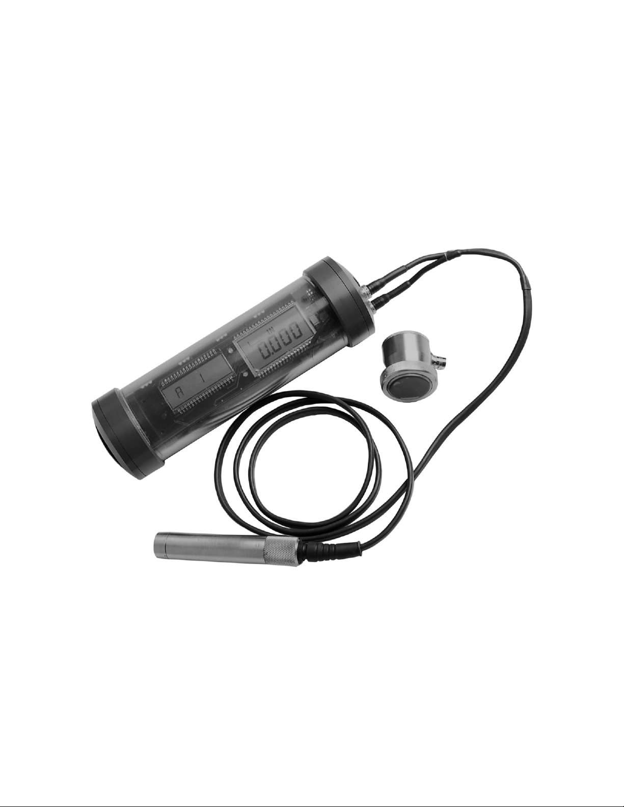
The Dakota Ultrasonics model UMX-2 is an underwater ultrasonic thickness gauge
that measures with extreme versatility. It has the ability to simultaneously measure
coatings and material thicknesses while maintaining the ability to locate pits, flaws
and defects in the material. It can also use a combination of dual and single element
transducers, depending on the application requirements. Based on the same
operating principles as SONAR, the UMX-2 is capable of measuring the thickness of
various materials with accuracy as high as ± 0.001 inches, or ± 0.01 millimeters. The
principle advantage of ultrasonic measurement over traditional methods is that
ultrasonic measurements can be performed with access to only one side of the
material being measured.
Dakota Ultrasonics maintains a customer support resource in order to assist users
with questions or difficulties not covered in this manual. Customer support may be
reached at any of the following:
Dakota Ultrasonics Corporation
1500 Green Hills Road, #107
Scotts Valley, CA 95066 USA
Telephone: (831) 431-9722
Facsimile: (831) 431-9723
http://www.dakotaultrasonics.com
1.1 Care & Maintenance
The UMX-2 housing is made of a clear PVC material that is very durable and well
suited for this application given the following conditions are followed:
• Keep the UMX-2 out of direct sunlight as much as possible to avoid any
potential ‘crazing’ or stress cracking, as well as discoloration.
• Protect the housing from impact.
• Submerge or rinse the enclosure and transducers in fresh water following use.
• Warning: Do not exceed the depth limitation of 1000 ft. Failure adhere to this
warning may result in leakage, potential implosion and serious injury.
The housing is sealed by o-rings, one on each end cap, which require meticulous
care. In order to maintain a watertight seal, the o-rings and their mating surfaces
must be clean, free of foreign material, and lubricated with silicone grease.
1
Page 6

UMX-2 Underwater Material & Coating Thickness Gauge
The following procedure must be performed on the end cap o-rings before
each use:
1. Clean all old silicone grease from o-rings and mating surfaces using paper towels.
2. Inspect o-rings for foreign material (sand, seaweed, hair, etc.), cracks, cuts, soft
spots, or deformities. Replace o-ring if damaged. Inspect mating surfaces for
scratches, rough spots, dents, or cracks.
3. Apply thin, even coat of silicone grease to o-rings on each end cap using finger to
spread evenly . Inspect to be sure the o-ring has been properly fitted, and screw
the end cap back in place, until it has a nice snug fit.
1.2 Warranty
The UMX-2 is protected by a 3 year limited liability:
1. The manufacturer inspects and tests every UMX-2 for watertight integrity
before it is delivered.
2. The manufacturer will repair or replace at the manufacturer's option any
housing that proves to be defective in const ruction or materials within three
year of date of delivery.
3. The Manufacturer will repair or replace at the manufacturer’s option any
transducer that proves to be defective in construction or materials within 90
days of date of delivery, evaluated up to 1 years time.
4. The manufacturer is not liable for damage to equipment caused by leakage of
water into the housing, nor is the manufacturer liable for loss of data or income
there from as may result from such leakage. The manufacturer is not liable for
any accidents during which this housing was in use.
5. This warranty is void in the event of negligent handling of the housing
including, but not limited to, dropping the housing, modifications to the housing
by other than the manufacturer, improper care of the sealing components, and
exceeding the specified depth limitation of 1000 feet.
6. There is no express or implied warranty, nor warranty of merchantability,
except as stated by the manufacturer above.
7. The buyer understands that, because of the nature of this product, he/she
uses the housing at his/her own risk and agrees to hold the manufacturer
harmless, except as stated above.
2
Page 7

Dakota Ultrasonics
1.3 Disclaimer
Applies to dual element transducers: Inherent in ultrasonic thickness measurement
is the possibility that the instrument will use the second rather than the first echo from
the back surface of the material being measured. This may result in a thickness
reading that is TWICE what it should be. Responsibility for proper use of the
instrument and recognition of this phenomenon rest solely with the user of the
instrument. Other errors may occur from measuring coated materials where the
coating is insufficiently bonded to the material surface. Irregular and inaccurate
readings may result. Again, the user is responsible for proper use and interpretation
of the measurements acquired.
3
Page 8
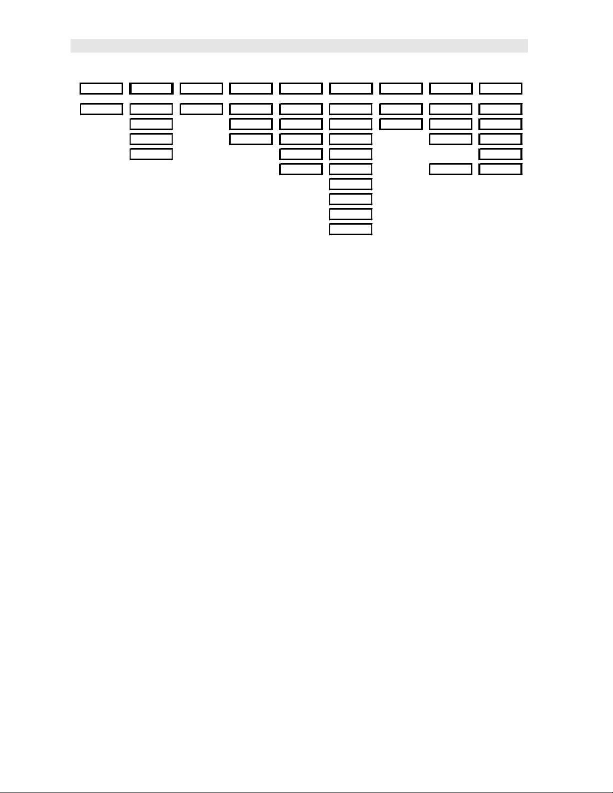
UMX-2 Single Element Menu Structure & Factory Configuration
CHAPTER TWO
QUICK STARTUP GUIDE
The UMX-2 is pre-configured at Dakota Ultrasonics with a specific and common
setup. As a result, the gauge should be ready to measure once the transducer has
been connected. Th e UMX-2 can use two different styles of transducers; dual
element and single element membrane. As a result, the gauge will be configured
according to the transducer style purchased, as follows:
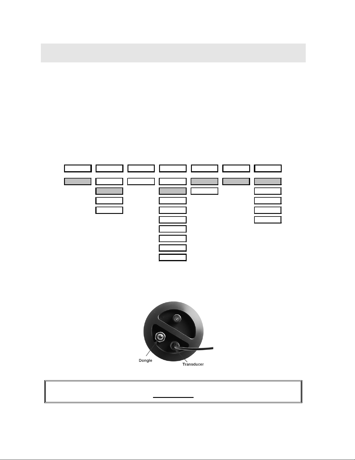
2.1 Factory Setup Parameters (Single)
Top Level
STORE DIRECT CLEAR MATL UNITS MODE UMX-2
A 1 NORTH LOC ALU IN E-E-E LT ON
SOUTH STL MM LT OFF
EAST STST LTAUTO
WEST IRON MEMOFF
CIRO UPGRAD
PYC
PLST
PLUR
CUSTOM
2.2 Quick Start (Single Element)
Procedure
4
Page 9
Dakota Ultrasonics
UMX-2 Dual Element Menu Structure & Factory Configuration
1) Referring to the diagram above, be sure the dongle and transducer are
connected as illustrated. Note: in order for the UMX-2 to recognize the
transducer that has been attached, it must be in the proper channel location.
2) Press and release the single button located on the end of the UMX-2. The
displays should illuminate, and led lights will begin flashing.
3) The smaller of the two displays will begin scrolling the current configuration
settings of the UMX-2 in the following order: UMX-2, BATT (LO, ME, HI),
Probe Type (1/2 2S or 5S)…etc. If ‘NO PRB’ is displayed, the dongle has
been plugged into the wrong channel. Press and hold down the button for
approximately 30 seconds, or until the UMX-2 powers off. Repeat steps 1 –
3 until the probe has been identified.
4) The UMX-2 is ready to begin making measurements.
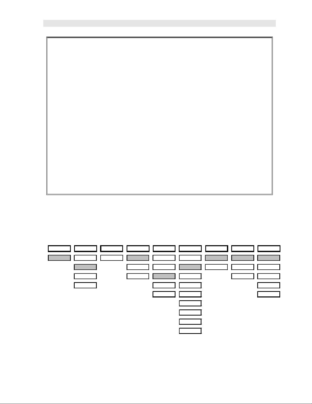
2.3 Factory Setup Parameters (Dual)
Top Level
STORE DIRECT CLEAR ZERO GAIN MATL UNITS MODE UMX-2
A 1 NORTH LOC AUTO VLOW ALU IN P-E LT ON
SOUTH MANUAL LOW STL MM PECT LT OFF
EAST COATIN MED STST E-E LTAUTO
WEST HIGH IRON MEMOFF
VHIGH CIRO UPGRAD
PYC
PLST
PLUR
CUSTOM
5
Page 10

UMX-2 Underwater Material & Coating Thickness Gauge
2.4 Quick Start (Dual Element)
Procedure
1) Attached the transducer to the UMX-2.
2) Press and release the single button located on the end of the UMX-2. The
displays should illuminate, and led lights will begin flashing.
3) The smaller of the two displays will begin scrolling the current configuration
settings of the UMX-2, and an auto zero will be performed.
4) The UMX-2 is ready to begin making measurements.
6
Page 11
CHAPTER THREE
OVERVIEW
Turn the UMX-2 on and off using the switch located on the bottom right corner of the
keypad. When UMX-2 is initially turned on, a UMX-2 logo will be displayed,
accompanied by lots of flashing led lights. The UMX-2 will attempt to ‘auto identify’
the transducer type that is connected, or display ‘NO PRB’ if the transducer cannot
be identified. The following sections outline each scenario. Note: This section is
primarily written as a basic startup guide only.
3.1 UMX- 2 Displays
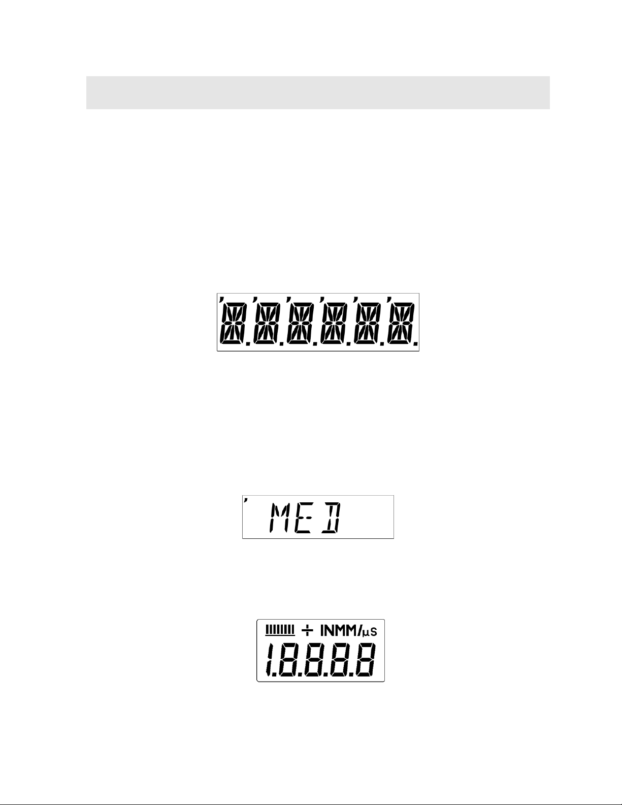
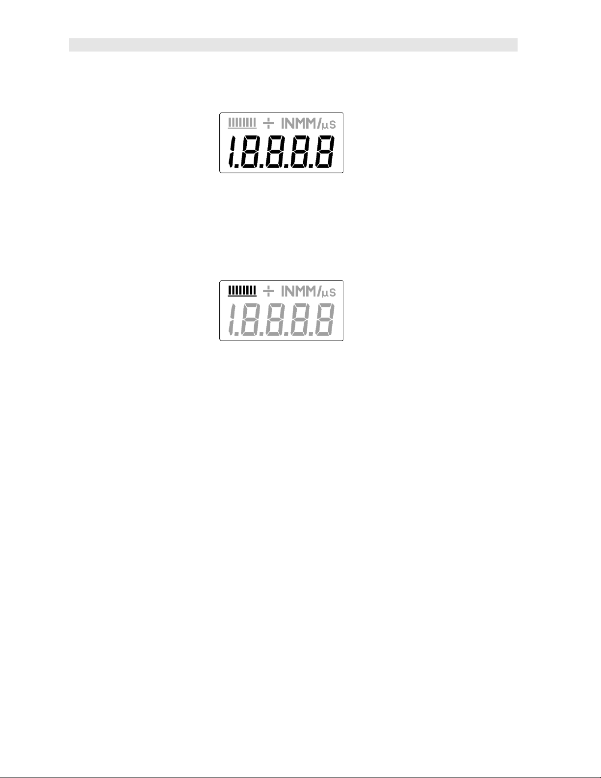
6 Character, 16 Segment Alpha Numeric Display
The UMX-2 is equipped with two segmented LCD displays that are used for entirely
different purposes. The 6 Character display above, is used for all the menu options
and any text to control the overall operation and functionality of the UMX-2. Since
the UMX-2 has the ability to store measurements, this display is also used to view
and move to specific cell/storage locations in the grid storage structure of the gauge.
Note: The left most ‘comma’ located in the top left corner of th e display, identifies
which sub menu feature option is currently selected, as shown above. In this
example the gain is currently set to medium.
7
Page 12
UMX-2 Underwater Material & Coating Thickness Gauge
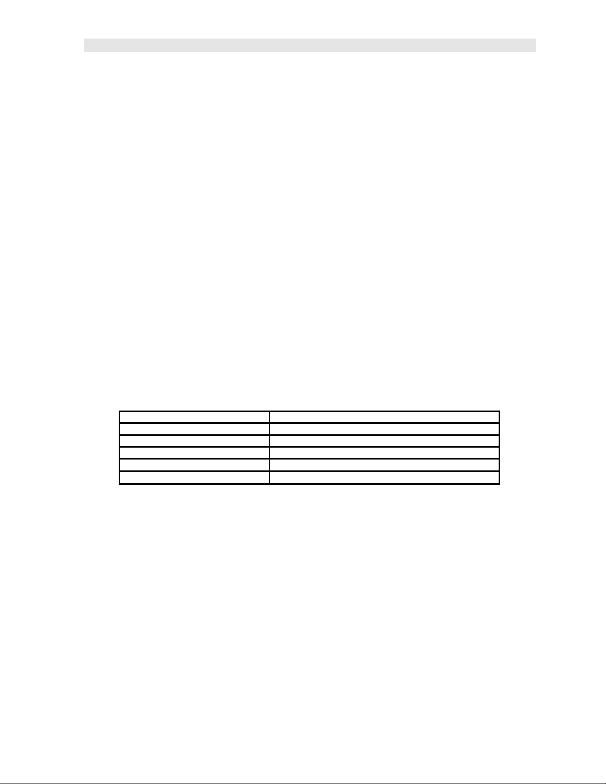
4 Digit , 8 Segment LCD Display
The 4 digit display illustrated above, is considered the primary measurement display
of the UMX-2. The following outlines the measurement display: The numeric portion
of the display consists of 4 complete digits preceded by a leading "1", and is used to
display numeric values, as well as occasional simple words, to indicate the status of
various settings. When the UMX-2 is displaying thickness measurements, the
display will hold the last value measured, until a new measurement is made.
These eight vertical bars form the Stability Indicator. When the UMX-2 is idle, only
the left-most bar and the underline will be on. When the gauge is making a
measurement, six or seven of the bars should be on. If fewer than five bars are on,
the UMX-2 is having difficulty achieving a stable measurement, and the thickness
value displayed will most likely be erroneous.
3.2 Single Button Operation
The UMX-2 is controlled using a single button to move around the menu structure
and enable/disable its features. There are 3 basic ‘button press’ sequences available
as follows:
Press & Hold:
Primary function – enter into, or exit out of the menu structure.
When the button is pressed and held down for a specific duration of time, the single
level menu structure will begin scrolling through the to p level of menu items
continuously. If entering into the menu structure, “Enter” will be displayed, followed
by scrolling through the menu items. If exiting the menu items, “Exit” will be
displayed, followed by advancing to the current storage location (i.e. A 1), or
“MEMOFF” if data storage has been disabled by the user. Once either instance has
occurred, the button can be released.
8
Page 13
Dakota Ultrasonics
Press & Release:
Primary function – selection of menu items.
To select a menu item, press and release the button. The sub menu items will begin
scrolling on the display. Finally, to select a sub menu item, press and rel ease again.
Press & Long Hold:
Primary function – manually turn off the UMX-2.
The UMX-2 will automatically shut off after 5 minutes if it hasn’t detected a
measurement. However, to be sure the unit is shut off after use, when the button is
pressed and held down for approximately 10 seconds, “POWER” “OFF” will be
displayed, and the unit will manually turn off . Once the unit turns off, the button can
be released.
It’s really just that simple!
3.3 Gauge Settings
The current settings of the UMX-2 will be displayed on initial power up and every 30
seconds following. This is intended to provide the user with an easy way to confirm
the settings at any time, without having to scroll to the specific menus items
individually. The parameters will be displayed in the order that follows:
Gauge Model:
Battery Status: LO, MED, or HI
Transducer Type Identified: ½ 5, ½ 3.5, ½ 2 S, ½ 5 S
Measurement Mode:
Current Gain Setting: VLOW, LOW, MED, HIGH, VHIGH
Material Type: ALU, STL, STST, IRON, CIRO, PVC, PLST, PLUR, or Custom
UMX-2
P-E, PECT, E-E or TCG
However, if the user is in the menus and viewing the sub menu items, the currently
selected option/featu re can be identified by the “,” (comma) illuminated in the top left
corner of the small display.
3.4 Menu Structure
The UMX-2 has been carefully designed to minimize the overall level of drop down
menu options in an effort to keep the gauge as simple to operate as possible. The
diagram below illustrates the entire menu structure of the UMX-2:
9
Page 14
UMX-2 Underwater Material & Coating Thickness Gauge
Top Level
STORE DIRECT CLEAR ZERO GAIN MATL UNITS MODE UMX-2
LOC NORTH LOC AUTO VLOW ALU IN P-E LT ON
SOUTH MANUAL LOW STL MM PECT LT OFF
EAST COATING MED STST E-E LTAUTO
WEST HIGH IRON MEMOFF
VHIGH CIRO E-E-E UPGRAD
PYC
PLST
PLUR
CUSTOM
Important comments:
• Depending on the transducer identified by the UMX-2, only the menu options
applicable to that specific transducer will appear. Therefore, it’s important to
note that the menus displayed are dynamic and may not be consistent if
different types of transducer are interchanged.
• Again, depending on the transducer identified, the modes applicable for that
specific probe type will be enabled and displayed. Dual element transducers
have mode options of P-E, PECT, or E-E. While the single element
membrane transducer options will only use our special TCG (time corrected
gain) triple echo mode (E-E-E), and all three modes listed above will be
deactivated and not displayed.
• If the MEMOFF has been activated, the data logging section of the gauge will
be temporarily turned off. This would be deactivated only if the user does not
intend to store measurements in the UMX-2. As a result, MEMOFF will
become the first ‘top level’ menu option, in place of a storage cell location (i.e.
A 1). Additionally, the top level menu items ‘DIRECT’ and ‘CLEAR’ will also
be temporarily deactivated from the menu options, as they pertain only to the
data storage facility of the UMX-2.
• If a custom material type has not been uploaded into the UMX-2, it will not
appear in the MATL subdirectory.
In general, if features and menu options start appearing/disappearing, as options
are activated/deactivated, it’s entirely based on the configuration settings and
probe identified by the UMX-2. The objective is to eliminate those items from the
menu structure that do not pertain to the mode or features activated/deactivated
by the user . It’s our effort to keep the available menu structure ‘simple’ and
‘intuitive’. All the features of UMX-2 will be further explain ed in later section of this
manual.
10
Page 15

STORE
DIRECT
CLEAR
ZERO
GAIN
MATL
UNITS
MODE
UMX-2
STORE
CLEAR
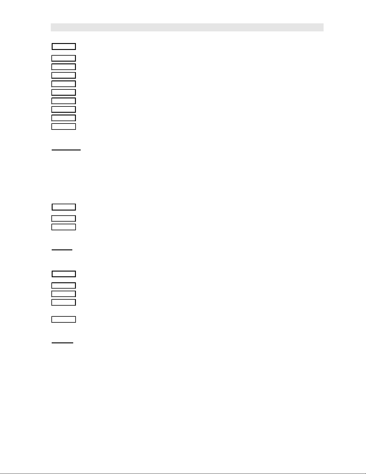
CHAPTER FOUR
MENU & CONNECTOR REFERENCE
4.1 Menu Options
Top Level
LOC
Store: This menu displ ays the current storage location of the UMX-2. This location
can refer to either a ‘grid’ cell location, like an Excel spreadsheet, or a sequential
format location, depending on which file format was uploaded into the gauge. If the
storage facility has been turned off, the menu label will read “MEMOFF”. The UMX-
2 will be shipped from the factory with a preloaded ‘grid’ file structure. Refer to the
section on page 43, for a detailed explanation.
DIRECT
NORTH
SOUTH
EAST
WEST
Direct: This menu item is also part of the data storage facility. It specifies which
direction to advance the cursor, after a measurement is stored. If a two dimensional
grid format is being used, all direction options can be used. However if a ‘sequential’
file format is used, only north and south are applicable. This menu item will not
appear if data storage has been disabled by the user. Refer to the section on page
52, for a det ailed explanation.
LOC
Clear: Again, this menu item is also part of the data storage facility. If a
measurement is stored by mistake, or in the wrong location, the measurement can be
cleared from memory using this option. The direction menu would be used to
advance to the location, and the ‘clear’ option would be used to erase the stored
measurement. If data storage has been disabled by the user, this menu item will not
appear as an option. Refer to the section on page 54, for a detailed explanation.
11
Page 16

UMX-2 Underwater Material & Coating Thickness Gauge
ZERO
AUTO
MANUAL
COATIN
Zero: The UMX-2 can use two different types of transducers, a dual or single
element. This menu item will only be visible if the UMX-2 identified a dual element
transducer connected.
• Auto – The auto zero feature of the UMX-2, performs an “off block” electronic
zero automatically, eliminating the need for a manual zero on a specified disk
or block. When the UMX-2 boots up, it will perform an auto zero during the
boot sequence. However, another auto zero may be need to account for
changes in temperature, or an incorrect zero due to couplant on the end of the
transducer during the zeroing process. Refer to the section on page 25, for a
detailed explanation.
• Manual – The UMX-2 is also equipped with an “on block” manual zero option.
This zero would only be used to reset the internal zero for of the UMX-2, as a
reference point for the auto zero. Note: the reference disk is located on the
end of the UMX-2 enclosure. Refer to the section on page 25, for a detailed
explanation.
• Coating - In order to account for very slight electronic differences in
transducers of the same type, frequency, and diameter, the UMX-2 has been
equipped with a “zero coating” feature. This zero is only used when the PECT
coating mode feature is being used. Although the coating thickness is not
displayed on the UMX-2 actual LCD displays, the coating thickness is stored
with the base material thickness when a measurement is saved to memory.
Once the data is downloaded to a PC, the coating thickness will be displayed
with PECT measurement stored. Refer to the section on page 40, for a
detailed explanation.
GAIN
VLOW
LOW
MED
HIGH
VHIGH
Gain: A 5 position gain switch in 2 db increments from 40 to 50 dB. Increase for
better penetration or punch, and decrease to eliminate unwanted noise or better
resolution. Refer to page 32 for further info.
12
Page 17
Dakota Ultrasonics
MATL
ALU
STL
STST
IRON
CIRO
PYC
PLST
PLUR
CUSTOM
Material: The UMX-2 includes a list of common material types with standard set
velocities. It’s important to note that the velocities associated with these materials
are general velocity values only. Materials of the same type, can have varying
grades and consistencies. As a result, the material velocity will also have slight
variations. A custom velocity has been implemented for this reason, and can be
programmed via DakView3 PC software. Refer to page 28 for further info.
UNITS
IN
MM
Units: Toggle between English or Metric units. The readout will change from inches
to millimeters. Refer to page 34 for further info.
MODE
P-E
PECT
E-E
E-E-E
Mode: The UMX-2 is equipped with a number of advanced measurement modes, to
satisfy a variety of application scenarios. The following is a brief description of each
mode. Refer to page 22 for further info:
• P-E (Pulse-Echo) – Common mode for measuring non-coated material (bare
metals).
• PECT (Pulse-Echo Coating) – A special mode used on coated materials to
measure the thickness of both; the base material and coating.
• E-E (Echo-Echo) – Common mode for measuring coated materials, and
measuring the base material only, without having to remove the coating.
13
Page 18

UMX-2 Underwater Material & Coating Thickness Gauge
• E-E-E (Triple Echo) – Special multiple echo mode used only with our single
element membrane transducers.
UMX-2
LT ON
LT OFF
LTAUTO
MEMOFF
UPGRAD
UMX-2: This is a general utility menu for miscellaneous features and functions.
The following is a brief explanation of each sub menu item. Refer to page 32 for
further information on upgrading the UMX-2:
• LT ON – Enables all the LED’s and display back lights.
• LT OFF – Disables all the LED’s and display back lights.
• LTAUTO – Powers all the LED’s and display back lights ‘on’ only when an
echo is detected (measurement). Refer to page 35 for further info.
• MEMOFF/ON - Toggles the data storage facility On or Off. Refer to page
51 for further info.
• UPGRAD – Feature to upgrade the firmware in the UMX-2 to the latest
version. Refer to page 65 for further info.
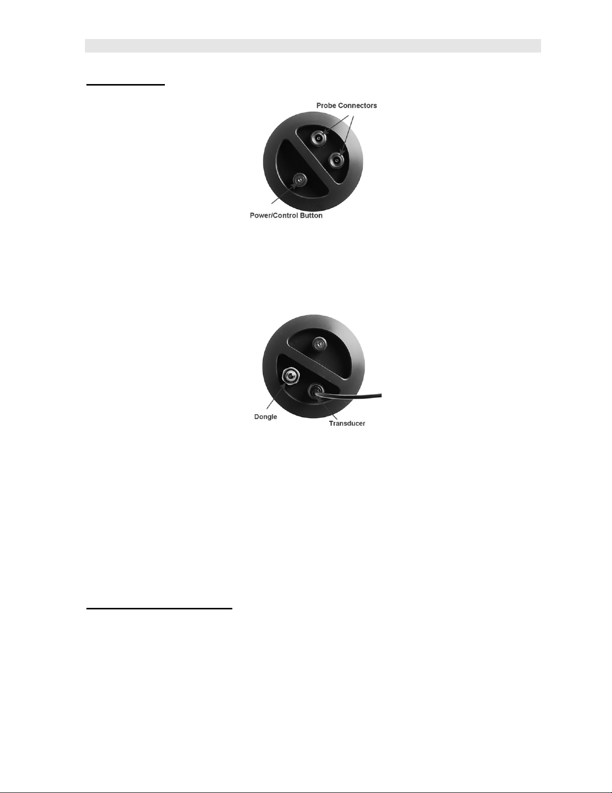
4.2 Top & Bottom End Caps
Top End Cap Bottom End Cap
The top & bottom inside end caps are where all connections are made to the UMX-2.
The bottom outside end cap also has a ‘zero reference standard’ attached. The
diagram above shows the layout and description of the connectors and zero
standard:
14
Page 19
Dakota Ultrasonics
Top End Cap :
Transducer Connectors
The transducer connectors and single control button are located on the top end cap
of the UMX-2. The transducer connectors are a special underwater Lemo “00”.
Note: There is no polarity associated with connecting a dual element transducer. If
a single element membrane style is connected, the dongle ‘must’ be plugged into the
connector labeled in the diagram above, in order for the UMX-2 to ‘auto identify’ the
single element probe type.
Single Control Button
The special magnetic reed found on the top end cap, provides single button
operation. Using this button and 3 basic press sequence options, the user can power
the UMX-2 on/off, enter the menu options, and change settings.
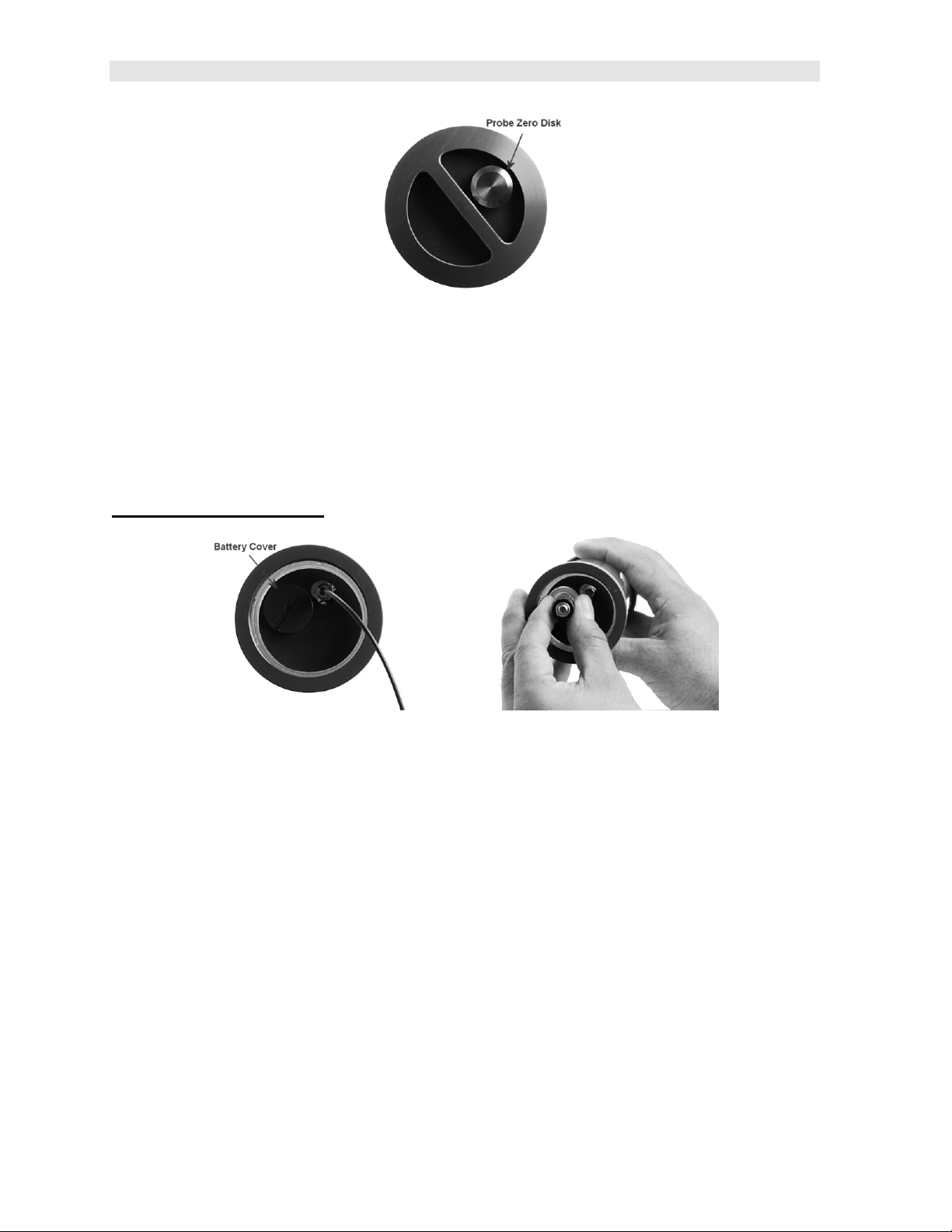
Bottom Outside End Cap:
15
Page 20
UMX-2 Underwater Material & Coating Thickness Gauge
Probe Zero Disk
The UMX-2 is equipped with an Auto Zero, which eliminates the user from having to
manually perform a zero on a specified zero standard. However, a Manual Zero
option has also been included with the UMX-2. This provides the user with the ability
to reset the internal zero used for the auto zero as a reset option. Other than for the
purposes of a safety mechanism, the Auto Zero feature will be used.
Bottom Inside End Cap:
Battery Cover
Simply remove the cover using a standard slot screw driver or other, and replace the
batteries.
Important: be sure the positive (+) battery terminal is facing up towards the battery
cover, when inserting them into the battery tube. This is very important! Failure to do
so will result in battery acid leakage cause by a current overload. The leakage can
permanently damage the circuit boards, should it leak through the battery tube. The
photo above shows demonstrates the polarity of the batteries. There is also a label
on the side of the battery tube for reference.
Note: Rechargeable batteries can be used, however they must be recharged outside
of the unit in a stand alone battery charger.
16
Page 21

Dakota Ultrasonics
RS-232 Connector
Refer to Diagram: The RS-232 connector is a 2 pin female LEMO connector. It is
designed to connect directly from the UMX-2 to a standard AT serial port on a PC or
into the supplied Serial to USB converter cable. There are two cables supplied with
the UMX-2;
• 2 pin LEMO to 9 pin serial cable
• 9 pin serial to USB converter cable.
Note: This connector is also used to upgrade the UMX-2 to the latest version of
firmware.
Serial to USB Converter Cable
A converter cable can be attached to the 9 pin serial cable, for computers that don
not have a serial port (part no. N-402-0510). This cable option is included in our kit
as standard.
17
Page 22

CHAPTER FIVE
PRINCIPALS OF ULTRASONIC MEASUREMENT
5.1 Time versus thickness relationship
Ultrasonic thickness measurements depend on measuring the length of time it takes
for sound to travel through the material being tested. The ratio of the thickness
versus the time is known as the sound velocity. In order to make accurate
measurements, a sound velocity must be determined and entered into the
instrument.
The accuracy of a thickness measurement therefore depends on having a consistent
sound velocity. Some materials are not as consistent as others and accuracy will be
marginal. For example, some cast materials are very granular and porous and as a
result have inconsistent sound velocities.
While there are many different ultrasonic techniques to measure thickness, which will
be discussed below, all of them rely on using the sound velocity to convert from time
to thickness.
5.2 Suitability of materials
Ultrasonic thickness measurements rely on passing a sound wave through the
material being measured. Not all materials are good at transmitting sound.
Ultrasonic thickness measurement is practical in a wide variety of materials including
metals, plastics, and glass. Materials that are difficult include some cast materials,
concrete, wood, fiberglass, and some rubber.
5.3 Range of measurement and accuracy
The overall measurement capabilities, based on the wide variety of materials, is
determined by the consistency of the material being measured
The range of thickness that can be measured ultrasonically depends on the material
as well as the technique being used and the type of transducer. Thickness
measurements can be made from a minimum of 0.010 in ch to 9.999” in steel.
However, the maximum attainable thickness is much less for more attenuative
materials (materials that absorb sound).
Accuracy, is determined by how consistent the sound velocity is through the sound
path being measured, and is a function of the overall thickness of the material. For
example, the velocity in steel is typically within 0.5% while the velocity in cast iron
can vary by 4%.
5.4 Couplant
All ultrasonic applications require some medium to couple the sound from the
transducer to the test piece. When the UMX-2 is used underwater as intended, the
water itself acts as a couplant. However when the UMX-2 is used above water, it
couplant will be required. Typically a high viscosity liquid is used as the medium.
18
Page 23

Dakota Ultrasonics
The sound frequencies used in ultrasonic thickness measurement do not travel
through air efficiently. By using a liquid couplant between the transducer and test
piece the amount of ultrasound entering the test piece is much greater.
5.5 Temperature
Temperature has an effect on sound velocity. The higher the temperature, the slower
sound travels in a material. High temperatures can also damage transducers and
present a problem for various liquid couplants.
Since the sound velocity varies with temperature it is important to calibrate at the
same temperature as the material being measured.
Normal temperature range
Most standard transducers will operate from 0°F to 180°F.
High temperature measurements
Special transducers and couplants are available for temperatures above 180°F up to
650°F with intermittent contact. It is necessary to cool the transducer, by submerging
the transducer in water between readings, when measuring high temperatures.
Modes and temperature errors
In addition to errors caused by velocity changing with temperature, some modes
(measurement techniques) are affected more than others. For example, dual
element pulse-echo mode has larger errors due to changes in the temperature of the
delay line. However, multi-echo techniques offer temperature compensation help to
minimize these errors.
5.6 Measurement Modes
In this section we will discuss the different measurements modes the UMX-2 is
capable of operating in, the transducers required, and the reasons for using specific
modes:
Pulse-Echo Mode (Flaw & Pit detection) – Coating Off (P-E)
Pulse-echo mode measures from the initial pulse (sometimes referred to as an
artificial zero) to the first echo (reflection). In this mode, either an automatic or
manual zero can be performed depending on the zero probe function setting. If the
manual mode has been selected, the transducer is placed on a reference disk,
located on bottom end cap of the UMX-2, and a manual zero is performed by
selecting the ‘manual’ sub menu option located in the ‘zero’ menu. If the Auto Zero
feature is enabled, a ‘zero reference standard’ is not necessary.
In this mode errors result from surface coatings and temperature variations.
19
Page 24

UMX-2 Underwater Material & Coating Thickness Gauge
Since pulse-echo only requires one reflection, it is the most sensitive mode for
measuring weak reflections (flaws) typically found when measuring heavily corroded
metals.
V-Path Correction
Dual element delay line transducers have two piezoelectric elements mounted at an
angle on one end of the delay line. One element is used for transmitting sound, while
the other element only receives sound. The two elements and their delay lines are
packaged in a single housing but acoustically isolated from each other with a sound
barrier. This allows the transducer the ability to achieve very high sensitivity for
detecting small defects. Also, the surface of the test material does not have to be as
flat in order to obtain good measurements.
Dual element transducers are normally used in pulse-echo mode for finding defects,
and in echo-echo mode for through coating measurements.
Dual element delay line transducers are usable over a range of 0.025 inches to 20
inches depending on the material, frequency, and diameter.
A limitation of dual element delay-line transducers is the V shaped sound path.
Because the sound travels from one elemen t to another, the time versus thickness
relationship is non-linear. Therefore, a correction table in the instruments software is
used to compensate for this error.
Dual Element Transducer showing V-path of signal
Searching for small defects
Dual element delay line transducers are especially useful in searching for small
defects. In the pulse-echo mode with high amplifier gain, very small defects can be
measured. This is very useful during corrosion inspections overall. The dual element
style transducer will find wall deterioration, pits, and any porosity pockets during tank
and pipeline inspections.
Echo-Echo Mode – Thru-Paint (E-E)
The echo-echo mode measures between two reflections. This technique is
commonly used to eliminate errors from surface coatings and also to make
measurements in multiple layered materials. The disadvantage is that two echoes
are needed which requires a much stronger echo (reflection).
20
Page 25

Dakota Ultrasonics
Dual Element Transducer in Echo to Echo mode
Pulse Echo Coating Mode – Coating On (PECT)
A custom hybrid combination mode using properties from the basic modes along with
a group of special techniques and theoretical wave phenomena’s to measure coating
and material thicknesses at the same time, while still retaining the ability to locate
flaw s and pits in materials. Therefore, the best description for this hybrid mode is
Pulse-Echo Coating mode.
Single Element Triple Echo Mode – Time Corrected Gain (TCG)
The TCG mode measures between 3 reflections. Similar to E-E mode, this technique
is commonly used to eliminate errors from surface coatings and also to make
measurements in multiple layered materials. The primary benefit of this mode, is that
a comparison is made, between the 2nd and 3rd echoes, to verify that a peak jump
has not occurred, providing an additional level of confidence to the measurement.
Generally the disadvantage is that 3 reflections are needed which requires the use of
gates with controllable thresholds to adjust for sensitivity over a given measurement
range. However, the time corrected gain feature built into this mode, automatically
adjusts the gain setting for each individual echo reflection. Therefore all three return
echoes are equal in amplitude or overall signal strength.
Single Element Transducer in Triple Echo (TCG) mode
21
Page 26

CHAPTER SIX
SELECTING THE MEASUREMENT MODE
6.1 Which mode & transducer do I use for my application?
High penetration plastics and castings
The most common mode for these types of applications is pulse-echo. The UMX-2
has been optimized for cast materials. Cast iron applications require 1 - 5MHz
frequencies, and cast aluminum requires higher frequencies from 7-10MHz
frequency. Plastics typically require lower frequencies depending on the thickness
and make-up of the material. Larger diameters offer greater penetration power
because of the crystal size, for difficult to measure materials.
Corrosion & Pit Detection in steel and cast materials
Use pulse-echo mode whenever attempting to locate pits and flaws. Typically a
5MHz transducer, or higher, will be used for these types of applications. Use low
frequencies for greater penetration and use higher frequencies for better resolution.
Measuring Material & Coatings
The pulse-echo coating mode should be used when both material and coating
thicknesses are required, while still requiring the ability to detect flaws and pits. A
special coating style transducer is required for use in this mode. There are a variety
of coating transducers in various frequencies available from Dakota. If a dual
element transduc er is selected with the UMX-2 kit, it will be a coating enabled
version.
Thru Paint & Coatings
Often times, users will be faced with applications where the material will be coated
with paint or some other type of epoxy material. Since the velocity of the coating is
approximately 2.5 times slower than that of steel, pulse-echo mode will induce error if
the coating or paint is not completely removed. By using echo-echo mode, the user
is able to successfully measure through both, the coating and steel, and completely
eliminate the thickness of the paint or coating. Therefore, the steel can be measured
without having to remove the coating prior to measuring. Users will often use pulseecho mode and echo-echo mode in conjunction when performing inspections on
coated materials.
Thru coating measurements require special high damped transducers. The most
common transducers are the 3.5, 5, and 7.5MHz hi damped transducers. These
transducers are suitable for use in both pulse-echo and echo-echo modes. This
conveniently enables the user to accurately measure overall material thickness using
the thru Coating mode, and then conveniently switch to pit detection mode without
changing transducers. The ¼” 5MHz Hi damped transducer is the most commonly
used transducer for standard thru coating applications.
22
Page 27

Dakota Ultrasonics
Thin materials
Use pulse echo mode and a high frequency transducer for these types of
applications. The most common transducers are the 7.5MHz and 10MHz models
with extra resolution. The higher frequencies provide greater resolution and a lower
minimum thickness rating overall.
High temperature
Use and select a special 2.25MHz and 5 MHz High temperature transducer for these
types of applications. Both pulse-echo and echo-echo modes will also work for these
applications. However, echo-echo mode will eliminate error caused by temperature
variations in the delay line of the transducer.
Noisy Material
Materials such as titanium, stainless steel, and aluminum may have inherent surface
noise issues. This is a signal that appears at the surface of the material when using
a dual element delay line probe. Select a higher frequency transducer to reduce this
noise – 7.5MHz and higher for better resolution.
Restricted access
Measuring materials with extreme curvatures or restricted access, higher frequencies
with smaller diameters should be considered. The smallest diameter uses 3/16”
crystals with a contact area of .250”. Custom transducers are available on request.
23
Page 28

CHAPTER SEVEN
MAKING MEASUREMENTS
The steps involved in making measuremen ts are detailed in this section. The
following sections outline how to setup and prepare your UMX-2 for field use. An
automatic or manual zero must always be performed when using a dual element style
transducer only. The single element membrane probe option uses a special multiple
echo mode, and does not require zeroing.
The auto zero is an off block electronic zero that does not require a zero reference
block. This will most always be the zero option of choice, as it makes the zeroing
process very easy and convenient to perform. However, if the manual zero option is
enabled, the probe zero must be measured on the reference disk attached to the
bottom end cap of the instrument. The zero compensates electrical variations and
delays for a given transducer. Like a mechanical zero, it’s a reference point. In all
modes the sound velocity must be determined. The sound velocity is used to convert
the transit time to a physical length. The sound velocity can be selected from a
preset list of material types in the UMX-2, or can be programmed with a custom
velocity using DakView3 utility software. Refer to page 28 for further info.
7.1 Auto Probe Recognition
The first step in using the UMX-2 is to plug the transducer into the gauge and power
the unit up. If a single element style transducer is used, be sure that the dongle is
connected to the correct LEMO connector, as illustrated above. The UMX-2 has a
special built -in automatic probe recognition feature that will check to see if the probe
plugged into the gauge was correctly identified. Note: only custom Dakota
Ultrasonics transducers will work with the UMX-2.
Auto Probe Recognition
24
Page 29

Dakota Ultrasonics
or
1) Connect the probe to the UMX-2.
2) Be sure all couplant has been removed from the face of the transducer.
3) Press and release the single button located on the end of the UMX-2. The
displays should illuminate, and led lights will begin flashing.
4) The smaller of the two displays will begin scrolling the current configuration
settings of the UMX-2 in the following order: UMX-2, BATT (LO, ME, HI),
Probe Type (1/2 2S or 1/2 5)…etc. If ‘NO PRB’ is displayed and a dual
element probe has been connected to the gauge, either the transducer is
faulty, or it is not a certified UMX-2 transducer. If a single element
membrane transducer has been connected, be sure the dongle is connected
to the correct channel. Press and hold down the button for approximately 30
seconds, or until the UMX-2 powers off. Repeat steps 1 - 4 until the probe
has been identif ied.
5) If the probe was identified, the UMX-2 will automatically perform a ‘probe
zero’.
7.2 Probe zero
Continuing on from the previous section, if a dual element transducer was connected
to the UMX-2, and the mode is currently setup either pulse-echo (P -E) or pulse-echo
coating (PECT), a probe zero will automatically be done following startup. Therefore,
if the UMX-2 was previously set to echo-echo mode, the user will first need to set the
gauge back to either pulse-echo or pulse-echo coating, before performing a probe
zero.
Note: multi-echo modes do not require a probe zero. A probe zero should be done
on a regular basis.
The probe zero function is an ‘electronic zero’ much like a mechanical zero used with
a set of calipers. If the UMX-2 is not zeroed correctly, all the measurements may be
in error by some fixed value. is in the echo-echo measurement mode and a manual
25
Page 30

UMX-2 Underwater Material & Coating Thickness Gauge
zero is being performed, the UMX-2 will put the gauge into pulse-echo mode
automatically before performing the zero. Both zero options are broken down again
as follows:
The UMX-2 is equipped with two zero options:
1) Off Block Zero (Automatic Probe Zero) – When this feature is enabled the
UMX-2 will do an electronic zero automatically, eliminating the need for a zero
disk or block.
2) On Block Zer o (Manual Probe Zero) – When this feature is enabled the
transducer must be placed on the probe zero disk located on the bottom end
cap.
Both zero procedures are outlined as follows:
Performing an Auto Probe Zero (Off Block)
1) Be sure all couplant has been removed from the face of the transducer.
2) Press and hold the single UMX-2 button, located on the top end cap, until
the top level menu options begin scrolling on the alpha display. Once this
occurs, the button can now be released. The menu options will scroll one to
the next in a time delayed sequence, and will display all the menu options in
a continuous loop.
3) When ZERO is displayed, immediately press and release the button to enter
the sub menu options. Again, the options will begin scrolling in a continuous
loop.
4) When AUTO is displayed, immediately press and release the button to
perform the auto zero.
26
Page 31

Dakota Ultrasonics
5) Press and hold the button to escape out of the menu options at any time.
6) The UMX-2 in now ready to be calibrated for a given material type.
Performing a Manual Probe Zero (On Block)
Note: When the manual probe zero option is either preferred, or needed to
reset the internal zero used for the auto zero, the ‘zero disk’ located on the
bottom end cap of the UMX-2 will be used as the zero reference standard.
1) Press and hold the single UMX-2 button, located on the top end cap, until
the top level menu options begin scrolling on the alpha display. Once this
occurs, the button can now be released. The menu options will scroll one to
the next in a time delayed sequence, and will display all the menu options in
a continuous loop.
2) When ZERO is displayed, immediately press and release the button to enter
the sub menu options. Again, the options will begin scrolling in a continuous
loop.
3) Apply a drop of couplant on the transducer and place the transducer in
steady contact with the probe zero disk and obtain a stable reading on the
27
Page 32

UMX-2 Underwater Material & Coating Thickness Gauge
measurement display . Note: Do not remove the transducer from the zero
reference standard.
4) When MANUAL is displayed, immediat ely press and release the button to
perform a manual probe zero.
5) Press and hold the button to escape out of the menu options at any time.
6) The UMX-2 in now ready to be calibrated for a given material type.
Note: The value that is displayed will change depending on the current velocity
setting in the UMX-2. Disregard the number that is displayed. It is not
important. What is important is accurately performing the steps outlined above
to insure reliability of the probe zero calculation.
7.3 Material Calibration
In order for the UMX-2 to make accurate measurements, it must be set to the correct
sound velocity of the material being measured. Different types of materials have
different inherent sound velocities. For example, the velocity of sound through steel
is about 0.233 inches per microsecond, versus that of aluminum, which is about
0.248 inches per microsecond. If the gauge is not set to the correct sound velocity,
all of the measurements the gauge makes will be erroneous by some fixed
percentage.
The UMX-2 has 8 preset material types with common fixed velocities to select from.
There is also 1 custom programmable velocity available for non-standard known
material velocities.
Basic Material Type
In order to calibrate the UMX-2 according to a specific material to be tested, the user
can select a basic material type from a list with approximate velocity values according
to various material types. It’s important to note that these velocities will not always
be an exact representation of the material being tested. They will typically be more
than adequate for ongoing ‘historical’ material degradation inspections. The following
is a list of the preset materials, and the procedure to select and calibrate the UMX-2:
UMX-2 Material Chart
Material Types Abbreviations Velocity Velocity m/sec
28
Page 33

Dakota Ultrasonics
in/µsec
Aluminum
Steel (4340 Mild)
Stainless Steel (304)
Iron
Cast Iron
PVC
Polystyrene
Poly Urethane
Custom
0.2500 6350
0.2330 5918
0.2229 5662
0.2320 5893
0.1800 4572
0.0940 2388
0.0920 2337
0.0700 1778
User User
Selecting Material Type
1) Press and hold the single UMX-2 button, located on the top end cap, until
the top level menu options begin scrolling on the alpha display. Once this
occurs, the button can now be released. The menu option s will scroll one to
the next in a time delayed sequence, and will display all the menu options in
a continuous loop.
2) When MATL is displayed, immediately press and release the button to enter
the sub menu options. Again, the options will begin scrolling in a continuous
loop.
3) When the material type is displayed, immediately press and release the
button to configure the UMX-2 to the selected material type. For this
example, IRON has been selected.
4) Press and hold the button to escape out of the menu options at any time.
29
Page 34

UMX-2 Underwater Material & Coating Thickness Gauge
5) The UMX-2 is now calibrated and ready to begin taking readings.
Preset Material Types & Velocities
If the material velocity is known, the user may wish to simply enter the velocity
number into the UMX-2, rather than have the UMX-2 calculate the velocity value
using a known thickness on a material sample. The steps for entering the velocity
are outlined below:
Using a Known Material Velocity
1) Press the MENU key once to activate the menu items tab. Press the MENU
key multiple times to tab right and the ESC key multiple times to tab left until
the CAL menu is highlighted and displaying the submenu items.
2) Use the UP and DOWN arrow keys to scroll through the sub menu items
until VELOCITY is highlighted.
3) Press the ENTER key to display the Digits Edit Box.
4) Press the UP and DOWN arrow keys to scroll the highlighted value.
5) Press the LEFT and RIGHT arrow keys to scroll the digit locations.
6) Repeat steps 4 & 5 until the velocity number is correctly displayed.
7) Press the OK key to set the velocity and return to the menu screen, or ESC
to cancel entering the velocity.
8) Finally, press the MEAS key to return to the measurement screen and begin
taking readings.
30
Page 35

Dakota Ultrasonics
To calibrate the UMX-2 for a specific type of coating using the DakView3 utility
software, refe r to page 58 for a complete explanation on how to program a known
coating velocity into the UMX-2.
31
Page 36

CHAPTER EIGHT
ADDITIONAL FEATURES & OPTIONS
8.1 Power Off
The UMX-2 will power off automatically after approximately 4 minutes without
receiving an echo (measurement). It should be noted that if the transducer face is
not wiped clean, there’s a chance an echo can continuously be detected. If that
happens, the gauge will remain on until the battery life is exhausted. As a result, the
UMX-2 can also be powered down manually as follows:
Manual Power Off
1) Press and hold the single UMX-2 button, located on the top end cap. Once
the UMX-2 is approaching power off status, “P OWER”…”OFF”, will be
displayed in a loop on the alpha display, and the UMX-2 will shut down.
This takes approximately 10 seconds. Once the gauge is off, the button can
be released.
8.2 Gain
The gain feature will only be displayed as a menu option if a ‘dual element’ style
transducer has been connected, and the UMX-2 is in either ‘pulse-echo (P-E) or
‘pulse-echo coating (PECT)’ modes. Multiple echo modes, which include both single
and dual style probes, are equipped with ‘automatic gain control (AGC) that optimizes
the gain setting automatically in the hardware of the UMX-2..
Gain, or amplification of the return echoes, can be adjusted in the UMX-2 to
accommodate a variety of applications. The setting of the gain is crucial in order to
obtain valid readings during the measurement process. Too much gain may result in
erroneous measurements, by detecting on noise rather than the actual material back
wall itself. Not enough gain may result in intermittent detection. It may also result in
lack of detection on internal flaws, pits, or porosity. The gain can easily be compared
to the volume control of a home stereo system. If you turn it up too much, you can’t
hear the music clearly. If it’s turned down too much, you can’t hear it at all.
The UMX-2 has three gain settings (VLOW, LOW, MED, HI, VHI). The gain range is
42dB – 50dB in 2dB increments. Note: The UMX-2 has been optimized for the MED
gain setting for all common applications. It should be operated in this mode as
standard. However, some applications may require the lower or higher gain settings.
32
Page 37

Dakota Ultrasonics
When? The low settings may be necessary for noisy or granular cast materials. How
do I know when to lower the gain? If the reading becomes sporadic and won’t settle
down or resolve on a thickness value, the user can assume that the material is either
very noisy aluminum, or granular cast iron. This would be a good time to change the
UMX-2 to lower gain setting and see if the reading settles down and become stable.
How do I know when to increase the gain? Often times the user will be trying to
measure a material that is hard to penetrate or pass sound through. This may be
due to the material type, or overall thickness of the material. When a material is hard
to pass sound through because of the thickness or general make-up, it would be a
good time to consider switching th e UMX-2 into a higher gain setting. Another
example might be the need to increase overall sensitivity for locating fine pits or
flaws. In any case, the selectable gain settings offer the user some additional options
to resolve and overcome application issues.
The procedures to adjust the Gain are outlined below:
Adjusting the Gain
1) Press and hold the single UMX-2 button, located on the top end cap, until
the top level menu options begin scrolling on the alpha display. Once this
occurs, the button can now be released. The menu options will scroll one to
the next in a time delayed sequence, and will display all the menu options in
a continuous loop.
2) When GAIN is displayed, immediately press and release the button to enter
the sub menu options. Again, the options will begin scrolling in a continuous
loop (VLOW, LOW, MED, HIGH, VHIGH).
33
Page 38

UMX-2 Underwater Material & Coating Thickness Gauge
3) When the desired gain setting is displayed, immediately press and release
the button to set the gain in the UMX-2. For this example, MED has been
selected.
4) Press and hold the button to escape out of the sub menu options at any
time.
8.3 Units (in/mm)
The UMX-2 can be set to either English or Metric units. The procedure below
outlines how to set the units in the UMX-2:
Setting Units
1) Press and hold the single UMX-2 button, located on the top end cap, until
the top level menu options begin scrolling on the alpha display. Once this
occurs, the button can now be released. The menu options will scroll one to
the next in a time delayed sequence, and will display all the men u options in
a continuous loop.
2) When UNITS is displayed, immediately press and release the button to
enter the sub menu options. Again, the options will begin scrolling in a
continuous loop (IN, MM).
34
Page 39

Dakota Ultrasonics
3) When the desired units are displayed, immediately press and release the
button to set the units in the UMX-2. For this example, IN has been
selected.
4) Press and hold the button to escape out of the sub menu options at any
time.
8.4 Display Backlights & LEDs
Depending on the required visibility versus power consumption, the UMX-2 provides
three lighting options; On, Off, AUTO. The following describes each option:
LT ON: Toggles both the display backlights and LED’s on.
LT OFF: Toggles all the lights off.
LAUTO: Toggles both the display backlights and LED’s on, only when receiving an
echo (measurement).
The following procedure explains how to set the lighting option in the UMX-2:
Setting Light Option
1) Press and hold the single UMX-2 button, located on the top end cap, until
the top level menu options begin scrolling on the alpha display. Once this
occurs, the button can now be released. The menu options will scroll one to
the next in a time delayed sequence, and will display all the menu options in
a continuous loop.
35
Page 40

UMX-2 Underwater Material & Coating Thickness Gauge
2) When UMX-2 is displayed, immediately press and release the button to
enter the sub menu options. Again, the options will begin scrolling in a
continuous loop (LT ON, LT OFF, LAUTO, MEM ON/OFF, UPGRAD).
3) When the desired light option is displayed, immediately press and release
the button to set the option in the UMX-2. For this example, LT ON has
been selected.
4) Press and hold the button to escape out of the sub menu options at any
time.
36
Page 41

CHAPTER NINE
THRU PAINT MEASUREMENT TECHNIQUE
9.1 Introduction to Thru Paint Measurement (Dual Element Probes)
The principle behind thru paint measurement is by measuring the time between two
back wall echoes returning from the test material. Since both of these back wall
echoes travel the same path through the paint or coating, the thickness of the coating
is subtracted out of the measurement so that only the actual material thickness can
be measured. This feature saves the user a great deal of time scraping and
removing the coating from tanks and pipes during the inspection process.
The primary purpose of thru paint measurement is to determine actual or overall
material thickness by eliminating the coating thickness. Thru paint mode cannot be
used for flaw or pit detection. Therefore, inspectors may need to use echo-echo thru
paint mode in conjunction with the standard pulse-echo flaw detection mode for some
applications. Pipe and tube inspectors will use the echo-echo mode for pipes with
powder coatings, and pulse-echo mode for pipes without coating. The combination
of using both modes is ideal for the advanced inspectors needs.
Note: The procedure to select the measurement mode in the UMX-2 is located at
the end of this chapter.
9.2 Triple Echo (TCG) – Single Element Probes
The TCG mode was added to include single element membrane style transducers,
and operates using three individual return echoes. Each echo is then adjusted, in
terms of ‘gain’, to provide sufficient signal amplitude for each individual echo. This is
needed because, if you’re standing at the edge of a canyon and scream hello there,
each return echo becomes weaker than the first until the sound in gone.
Similar to echo-echo mode, the measurement is made between the first two return
echoes, eliminating the paint/coating and measuring only the based material.
However, a second measurement is made between the second and third echoes,
and compared to the first measurement. If both measurements are the same, the
stability indicator will fully light up, and a stable measurement will be displayed.
Advantages:
The primary advantage using a single element transducer is linearity. Since only one
crystal is used, and perfectly flat, a correction curve is not needed to compensate for
focusing issues. A second advantage would be the comparison made between two
different sets of echoes.
37
Page 42

UMX-2 Underwater Material & Coating Thickness Gauge
Disadvantages:
Single element transducers are not capable of detecting pits and flaws with a digital
thickness gauge, and are typically not used for corrosion inspections on blind
surfaces. Since only one crystal is used to both send and receive sound waves,
small defects that reflect very little sound energy back to the transducer are ignored,
based on the noise created by the same crystal sending the sound wave. Therefore,
these transducers should only be used when general material thickness is required,
and ‘never’ used for corrosion inspections. If there’s any interest in locating blind
surface pitting or internal material flaws, a ‘dual element’ transducer should always
be used.
38
Page 43

CHAPTER TEN
PULSE-ECHO COATING & COATING TECHNIQUES
10.1 Introduction to Pulse- Echo Coating Measurement (PECT)
In the previous sections we’ve discussed the need for detecting pits and flaws (pulseecho) in materials, along with the requirement to measure through and eliminate
errors caused by coated materials (echo-echo). Until now, both modes were needed
in order accomplish both tasks. Pulse-echo mode was used for flaw detection, and
echo-echo mode was used to eliminate the coating thickness and provide a nominal
material thickness only. With this in mind, it often became cumbersome toggling
between both modes respectively.
In a majority of applications involving coat ed materials, inspectors are often
interested in monitoring both the thickness of the material, as well as the thickness of
the coating. Therefore, the UMX-2 has been designed to provide the user with the
ability to measure the material and coating thicknesses simultaneously, while
maintaining the ability to detect flaws and pits all in a single mode called Pulse-Echo
Coating (PECT) . This is accomplished by using a custom hybrid combination mode
utilizing properties from the basic modes along with a group of special techniques
and theoretical wave phenomena’s.
The UMX-2 is preset to a coating velocity of 0.0850 in/µsec (2159 m/sec) from the
factory. This velocity is a very close approximation of the common coating velocities
found in the field. However, this can be changed to another known coating velocity,
using DakView3 utility software to set a ‘custom’ velocity that can be uploaded to the
UMX-2.
10.2 Enabling Pulse-Echo Coating Mode (PECT)
The special PECT mode is only available for use with ‘dual element’ transducers.
When the UMX-2 is initially powered up, the gauge will automatically check to see if
the transducer plugged into the gauge can be recognized. All Dakota Ultrasonics
coating enabled transducers are equipped with the auto recognition feature. If the
UMX-2 doesn’t recognize that a special coating enabled transducer is plugged into
the gauge, the coating feature will be disabled entirely. There are a number of
coating enabled transducers available from Dakota. Please contact us with your
application requirements for additional information on frequencies and diameters
currently offered.
Note: When PECT mode is used, the coating value cannot be viewed on the UMX-2.
Only the base material thickness is displayed. However, if the measurements are
stored to a file and downloaded to a PC, the coating measurements can be viewed
as they are saved within the file. The actual A-Scan waveform is also stored in the
file. This can prove very valuable, as it provides the inspector additional confidence
that the measurement was successful overall. Finally, all UMX-2 settings are also
39
Page 44

UMX-2 Underwater Material & Coating Thickness Gauge
saved for each individual reading, again offering confidence and detail for reporting
purposes.
The following procedure demonstrates how to enable PECT mode:
Enabling PECT Mode
1) Press and hold the single UMX-2 button, located on the top end cap, until
the top level menu options begin scrolling on the alpha display. Once this
occurs, the button can now be released. The menu options will scroll one to
the next in a time delayed sequence, and will display all the menu options in
a continuous loop.
2) When MODE is displayed, immediately press and release the button to
enter the sub menu options. Again, the option s will begin scrolling in a
continuous loop (P-E, PECT, E-E).
3) When the desired option is displayed, immediately press and release the
button to set the option in the UMX-2. For this example, PECT has been
selected.
4) Press and hold the button to escape out of the sub menu options at any
time.
10.3 Zero Coating
In order to account for very slight electronic differences in transducers of the same
type, frequency, and diameter, the UMX-2 has been equipped with a “zero coating”
40
Page 45

Dakota Ultrasonics
feature. This enables the UMX-2 to obtain very accurate readings on coatings,
eliminating potential errors incurred from slight differences in the manufacturing
processes. The coating zero should be performed on an uncoated section of the
same material or something similar. The procedure is outlined below:
Performing a Coating Zero
1) Press and hold the single UMX-2 button, located on the top end cap, until
the top level menu options begin scrolling on the alpha display. Once this
occurs, the button can now be released. The menu options will scroll one to
the next in a time delayed sequence, and will display all the menu options in
a continuous loop.
2) When ZERO is displayed, immediately press and release the button to enter
the sub menu options. Again, the options will begin scrolling in a continuous
loop (AUTO, MANUAL, COAT).
3) Apply a drop of couplant on the transducer or test material . Place the
transducer on an uncoated surface of the material and obtain a stable
measurement. Do not remove the transducer.
4) When the desired option is displayed, immediately press and release the
button to set the option in the UMX-2. For this example, COAT has been
selected.
5) Press and hold the button to escape out of the sub menu options at any
time.
41
Page 46

UMX-2 Underwater Material & Coating Thickness Gauge
10.4 Coating Calibration (PECT)
Known Velocity
If the coating velocity is known, and other than the factory set velocity of 0.0850
in/µsec (2159 m/sec), the user may wish to program the UMX-2. In order to set the
coating velocity, the DakView3 PC software must be used to create a setup, and
upload the setup into the UMX-2. Refer to page 58 regarding setups.
42
Page 47

CHAPTER ELEVEN
DATA STORAGE – SETUP, EDIT, & VIEW FILES
11.1 Introduction to Grid and Sequential file formats
The UMX-2 is equipped with two data file format options, GRID LOG and SEQ LOG.
The GRID file format is very similar to a spreadsheet format found in popular
software programs like Excel. A GRID is simply a table of readings. A location in a
grid is specified by giving a row and column coordinate. The rows are numbered
from 1 to 999 and the columns are labeled from A to ZZ (999 Rows & 52 Columns).
The sequential file format can be viewed as a file as a single column of up to 512
possible rows (readings), and a column of corresponding identifiers associated with
each individual reading. The identifier can be a combination of up to 10 numeric,
alpha, or special characters listed above, while the file name can consist of a
combination of up to 20 of the same character set. Note: The identifier cannot start
or end with a special character. Once a start and end ID are entered into the UMX-2
and the log created, the UMX-2 will automatically generate all the identifiers within
that range.
The following character set listed below are all the allowable characters that will be
used for both file formats: GRID & SEQ LOG. Any combination of these characters
can be used for creating a Name and Note regardless of the selected format. The
allowable characters are as follows:
Numeric characters: 0 – 9 Alpha Characters: A – Z
Special Characters: ! ‘ _ # space / . – ( )
Note: Multiple grids can be created and saved as template files on a PC, using
DakView3 utility software, but only one grid can be uploaded into the UMX-2 at a
time.
The UMX-2 can store a total of 16,000+ readings with a corresponding screenshot of
the actual waveform, as well as all the UMX-2 settings for every individual reading. If
the graphics option is disabled, not saving screenshots, the UMX-2 can store a total
of 210,000+ readings.
In the sections that follow, the procedures for creating, using, and editing GRID’s and
SEQ LOG’s have been combined together for the purpose of similarity in overall
functionality and structure. The illustrations below are snapshots of typical GRID and
SEQ LOG file formats:
Grid File Formats
43
Page 48

UMX-2 Underwater Material & Coating Thickness Gauge
Sequential Log Formats
Important Note: For the duration of this chapter, all references to GRIDS and SEQ
LOGS should be considered synonymous with references to FILES.
11.2 Create New Log Field Definitions
Coordinates or Start & Stop ID’s
Grid: A grid is defined by using coordinates to define the Top Left and the Bottom
Right corners of the grid. Alpha coordinates are horizontal across the top, and
numeric coordinates are vertical down the side. Therefore, to define the top left
44
Page 49

Dakota Ultrasonics
corner of the grid, there will be an (X,Y) coordinate. Where X is an alpha column
location across the top and Y is a numeric row location down the side. Use the same
logic when choosing the lower right corner. An individual grid can be up to 999 r ows
and 52 columns. If the user attempts to create a grid that is larger than the stated
boundaries, an error message box “OUT OF MEMORY“ will be displayed.
Sequential: The sequential file format can be viewed as a file as a single column of
up to 512 possible rows (readings), and a column of corresponding identifiers
associated with each individual reading. The identifier can be a combination of up to
10 numeric, alpha, or special characters listed above, while the file name can consist
of a combination of up to 20 of the same character set. Note: The identifier cannot
start or end with a special character. Once a start and end ID are entered into the
UMX-2 and the log created, the UMX-2 will automatically generate all the identifiers
within that range. If the user attempts to create a grid that is larger than the stated
boundaries, an error message box “OUT OF MEMORY“ will be displayed.
Selecting the Auto Increment Direction
The Auto Increment feature gives the user the ability to specify which direction to
advance the cursor after storing a reading.
Saving Graphics
The UMX-2 provides the user with the ability to save a snapshot of the display screen
and all the current settings of the UMX-2 with every reading, or just save the reading
only. Saving the graphics might be advantageous to the user for reporting purposes,
and additional confidence in the measurements, as a snapshot of the actual A-Scan
waveform will be recorded for every individual reading. This offers the user the ability
to review and confirm the validity of the measurements, based on the waveforms.
Additionally, enabling this feature will store all the current UMX-2 setup parameters
for each measurement.
11.3 Creating a new Grid or Sequential Log (File)
This section will go through the step to create a Grid/Log file and save it on your PC,
as follows:
Creating a Grid/Log File
45
Page 50

UMX-2 Underwater Material & Coating Thickness Gauge
Note: This section assumes that DakView3 has already been installed on your
PC, has been executed, and ready to go.
1) A log file can be created two different ways; Click the icon button to initiate
the ‘New Log’ dialog box, or click FILE, followed by clicking NEW.
2) Click in the ‘white space’ fields, or on the down arrows next to the fields to
enter the options for the file template, as illustrated above.
46
Page 51

Dakota Ultrasonics
3) When all the information has been entered into the fields, click the OK
button to create and display the log file.
4) The log file can be saved two different ways; Click the icon button to initiate
the ‘SAVE’ dialog box, or click FILE, followed by clicking SAVE.
5) Specify the path to the folder to store the log file in, give the log file a unique
name, and click save to store the file on your PC.
47
Page 52

UMX-2 Underwater Material & Coating Thickness Gauge
11.4 Connecting to a PC
Now that the log file has been created and saved on the PC, the next step is
connecti ng to a PC to transfer the template file into the UMX-2. There are 2 cables
included with the UMX-2 kit; LEMO to 9 pin serial and 9 PIN serial to USB.
Serial:
The LEMO to 9 pin RS232 cable can be connect directly to any serial port. However,
the serial port number must be known. The actual port reference can be obtained in
the device manager of a Windows® based operating system.
USB:
Both the LEMO to 9 pin serial and 9 pin serial to USB can be connected together to
use the serial to USB converter configuration. This option requires that a driver is
installed for the USB cable. The driver will automatically be loaded when DakView3
PC software is installed. However, the driver files will also be included in the
‘examples’ folder on your desktop. This folder is created by DakView3 when
installed.
The following procedure outlines the steps for connecting and transferring the
template file to the UMX-2 as follows:
Uploading the Log File
1) Remove the bottom end cap of the UMX-2, in order to access the LEMO
data jack. Remove the rubber plug from the data jack.
2) Plug the LEMO connector into the data jack. Note: align the red pin on the
connector with the data jack.
48
Page 53

Dakota Ultrasonics
3) Plug either the RS232 into a serial port, or USB connector into a USB port
on the PC.
4) Start the DakView3 utility software.
5) Click on SETTINGS, followed by clicking on COM PORT, to view the list of
available ports. The default setting for DakView3 is always AUTO. The
AUTO mode searches through all the possible com port options, and looks
for the port ‘automatically’. However, this can take some time. Therefore, if
the port is already known, manually select the port from the list.
49
Page 54

UMX-2 Underwater Material & Coating Thickness Gauge
Note: A list of available ports can be determined in the device manager of the
Windows® operating system.
6) Power on the UMX-2, and give it a minute to fully boot up.
7) Click the UP ARROW icon to initiate the file transfer. A dialog box will
appear, displaying the examples folder created by DakView3 on your
desktop. Alternatively, the upload can be initiated from the menus by
50
Page 55

Dakota Ultrasonics
clicking the FILE menu option, followed by clicking the UPLOAD TO GAUGE
option.
8) Select the file to be uploaded to the UMX-2.
9) Finally, click the UPLOAD button in the dialog box to start the transfer. A
progress bar will appear on the screen during the transfer process, and
disappear once the transfer has completed.
11.5 Activating the Data Logger (UMX- 2)
The following procedure explains the necessary steps to activate the data logger in
the UMX-2:
Turning on the Data Logger
Note: This section assumes the UMX-2 is powered up and ready to go. The
UMX-2 always boots up and displays the left most top level menu item, which
corresponds to the data logger. If anything, other than MEMOFF, is currently
displayed, the data logger is already active.
1) Press and hold the single UMX-2 button, located on the top end cap, until
the top level menu options begin scrolling on the alpha display. Once this
occurs, the button can now be released. The menu options will scroll one to
the next in a time delayed sequence, and will display all the menu options in
a continuous loop.
2) When UMX-2 is displayed, immediately press and release the button to
enter the sub menu options. Again, the options will begin scrolling in a
continuous loop (LT ON, LT OFF, LAUTO, MEM ON/OFF, UPGRAD).
51
Page 56

UMX-2 Underwater Material & Coating Thickness Gauge
3) When the desired option is displayed, immediately press and release the
button to set the option in the UMX-2. For this example, MEMOFF has been
selected to toggle MEM ON.
Note: MEMOFF & ON is a two position toggle switch. Therefore, if MEMOFF
is selected, it turn the data logger on, and visa versa.
4) Press and hold the button to escape out of the sub menu options at any
time.
11.6 Navigating the Data Logger
When the Grid or Sequential log file was created in the DakView3 PC utility software,
one of the selection options was an increment direction. The increment direction
specifies which ‘direction’ to advance the cursor following storage of a measurement.
The directions are like a compass; North, South, East, West and None. If None is
selected, the user will have to manually set the increment direction in the UMX-2.
The user might also consider changing this direction, even if the original increment
direction was previously set in the PC software. The user may opt to use a variety of
directions, considering efficient use of inspection locations, not previously
considered. Finally, the user may want to go back to previously stored
measurements to review them. The section that follows, outline the necessary steps
to change the increment direction and navigate through the log file:
Changing the Increment Direction
Note: This section assumes the UMX-2 is powered up and ready to go.
1) Press and hold the single UMX-2 button, located on the top end cap, until
the top level menu options begin scrolling on the alpha display. Once this
occurs, the button can now be released. The menu options will scroll one to
52
Page 57

Dakota Ultrasonics
the next in a time delayed sequence, and will display all the menu options in
a continuous loop.
2) When DIRECT is displayed, immediately press and release the button to
enter the sub menu options. Again, the options will begin scrolling in a
continuous loop (NORTH, SOUTH, EAST, WEST, Current Log Location ).
3) When the desired direction is displayed, immediately press and release the
button to set the option in the UMX-2. For this example, SOUTH has been
selected as the increment direction.
Note: If the user wants to ‘fast’ increment through a variety of storage
locations, follow step 3 above, and continuously ‘press and release’ to move
through storage locations. Example: current grid cell location is A1, and user
needs to move to A5. Repeat a ‘press and release’ when SOUTH appears, five
times repetitively.
4) Press and hold the button to escape out of the sub menu options at any
time.
11.7 Storing a Measurement
Now that a grid or sequential log has been created and uploaded to the UMX-2, and
the user is familiar with moving around through the log file, it’s time to take and store
a measurement. The following procedures outline this process:
Storing Measurements
53
Page 58

UMX-2 Underwater Material & Coating Thickness Gauge
Note: This section assumes the UMX-2 is powered up and ready to go. Also,
the UMX-2 will always return to the left most top level menu item, or the current
log file location. This was done to make it convenient for the operator to store
measurements without having to scroll through directories.
1) Press and release the single UMX-2 button, located on the top end cap, to
store a measurement, and auto increment to the next storage location.
Example: current grid cell location is A1, and auto increment is set to south.
Once the reading is stored, the cursor will automatically advance to A2.
2) It’s as simple as that!
Important Note: If the UMX-2 is currently in a stored location, the gauge will
not measure. The measurement must be cleared first, or the user must be in
an ‘empty’ storage location.
11.8 Clearing a Stored Measurement
The following procedure outlines the steps to clear a cell or log location, where the
user has opted to make and store another measurement for that specific location:
Clear Location
Note: This section assumes the UMX-2 is powered up, and the user has
navigated to the storage location that will be cleared.
1) Press and hold the single UMX-2 button, located on the top end cap, until
the top level menu options begin scrolling on the alpha display. Once this
occurs, the button can now be released. The menu options will scroll one to
54
Page 59

Dakota Ultrasonics
the next in a time delayed sequence, and will display all the menu options in
a continuous loop.
2) When CLEAR is displayed, immediately press and release the button to
enter the sub menu options. CLEAR followed by the current storage
location will alternate (CLEAR…A1…CLEAR…A1).
3) When CLEAR or LOCATION(A1) are being displayed, immediately press
and release the button to clear the current location in the UMX-2. For this
example, A1 has been selected as the storage location.
4) Press and hold the button to escape out of the sub menu options at any
time.
11.9 Downloading the Log File
Once all the measurements have been stored in the log file, the file can be
downloaded to a PC using DakView3 for the purpose of reporting and recordation.
The procedures are outlined in this section.
Note: REFER TO THE SECTION ON CONNECTING TO A PC SECTION
Download Log File
Note: This section assumes the UMX-2 is powered up and ready to go. The
earlier procedure for ‘connecting to a PC’ and ‘Upload Log File’ procedure
should be used for this section, to avoid redundancy . This section outlines only
minor changes to that procedure. The steps have been numbered for easy
insertion.
55
Page 60

UMX-2 Underwater Material & Coating Thickness Gauge
7) Click the DOWN ARROW icon to initiate the file transfer. A dialog box will
appear, displaying the examples folder created by DakView3 on your
desktop. Alternatively, the upload can be initiated from the menus by
clicking the FILE menu option , followed by clicking the DOWNLOAD FROM
GAUGE option.
8) Give the log file a unique name to store it on your PC.
9) Finally, click the DOWNLOAD button in the dialog box to start the transfer.
A progress bar will appear on the screen during the transfer process, and
disappear once the transfer has completed.
11.10 Viewing stored readings
Once the file download is complete, as performed in the previous section, the file will
automatically open and be displayed in DakView3. It is sometimes necessary to go
back and view the stored readings, their settings, and waveforms displays. The
following procedures outline this process:
Viewing a Log File
56
Page 61

Dakota Ultrasonics
1) Click on any of the measurement cells to review the gauge settings and
waveform for that specific measurement.
2) Click in the any of the ‘white space’ text fields’ to enter required information
for reporting purposes. If the file is then saved, the information entered will
also be saved with the file.
Note: Although the UMX-2 is not equipped with a screen to view an actual live
A-Scan waveform, a ‘snapshot’ of the waveform is captured for each and every
measurement saved. These waves can be opened and reviewed in DakView3
at any time. They can provide valuable information, in reference to the quality
of the measurements.
57
Page 62

CHAPTER TWELVE
SETUPS – CREATE, STORE, EDIT, & UPLOAD
12.1 Introduction to Setups
The UMX-2 has been programmed with 8 of the most common material types used in
the field. It’s important to note that these are ‘set’ velocity values and are ‘not exact’
velocities for each and every grade of the same material. For example: There are a
number of different grades of steel that can slightly vary in terms of velocity.
However, the amount of variation according to error in thickness is typically not
substantial. Inspectors are generally interested in ‘historical’ data (material
degradation) over a period of tim e. As a result, a standardized velocity setting acts
as a consistent reference to monitor degradation over time.
If a user is measuring a material type not preset in the UMX-2, and is not a close
enough fit for the specific material, the user can program the UMX-2 for a custom
material type, using the DakView3 utility software. This section will guide you
through all the necessary steps to create, store, and upload a setup.
12.2 Opening the Default Setup File
When DakView3 is installed on your computer, a folder named ‘examples’ is
automatically created on your desktop. The examples folder includes the UMX-2
setup file called “DEFAULT_UMX2.CSX”. This file will be used to create either a
custom material or coating velocity to be programmed into the gauge. The following
procedures outline how to open the factory setup file:
Default Setup File
58
Page 63

Dakota Ultrasonics
Note: This section assumes that DakView3 has already been installed on your
PC, has been executed, and ready to go.
1) The default setup file can be opened two different ways; Click the icon
button to initiate the ‘open’ dialog box, or click FILE, followed by clicking
OPEN.
2) Locate the file “DEFAULT_UMX2.CSX”. The file can be opened 2 ways.
Single click on the file name to highlight the file, followed by clicking the
open button. Alternatively, double click on the file name itself to open the
setup dialog box.
Note: This assumes that a setup file was not previously created and saved. If
it was, locate the file that was previously created and follow the same procedure
above.
59
Page 64

UMX-2 Underwater Material & Coating Thickness Gauge
3) There are two possible velocity settings available; material and coating. The
user can enter a known velocity number in either field by clicking in the
‘whitespace’ and the current velocity number, or select a material by clicking
on the DOWN ARROW located next to the material type.
4) Once the material and or coating velocities have been set, click the SAVE
button in the setup dial og box, to display the SAVE dialog box.
60
Page 65

Dakota Ultrasonics
5) Specify the path to the folder to store the setup file in. Give the setup file a
unique name, or overwrite the default file.
6) Finally, click the SAVE button to store the file on your PC.
12.3 Connecting to a PC
Now that the new setup file has been created and saved on the PC, the next step is
connecting to a PC to transfer the setup file into the UMX-2. There are 2 cables
included with the UMX-2 kit; LEMO to 9 pin serial and 9 PIN serial to USB.
Serial:
The LEMO to 9 pin RS232 cable can be connect directly to any serial port. However,
the serial port number must be known. The actual port reference can be obtained in
the device manager of a Windows® based operating system.
USB:
Both the LEMO to 9 pin serial and 9 pin serial to USB can be connected together to
use the serial to USB converter configuration. This option requires that a driver is
installed for the USB cable. The driver will automatically be loaded when DakView3
PC software is installed. However, the driver files will also be included in the
‘examples’ folder on your desktop. This folder is created by DakView3 when
installed.
The following procedure outlines the steps for connecting and transferring the setup
file to the UMX-2 as follows:
Uploading the Setup File
61
Page 66

UMX-2 Underwater Material & Coating Thickness Gauge
1) Remove the bottom end cap of the UMX-2, in order to access the LEMO
data jack. Remove the rubber plug from the data jack.
2) Plug the LEMO connector into the data jack. Note: align the red pin on the
connector with the data jack.
3) Plug either the RS232 into a serial port, or USB connector into a USB port
on the PC.
4) Start the DakView3 utility software.
5) Click on SETTINGS, followed by clicking on COM PORT, to view the list of
available ports. The default setting for DakView3 is always AUTO. The
AUTO mode searches through all the possible com port options, and looks
for the port ‘automatically’. However, this can take some time. Therefore, if
the port is already known, manually select the port from the list.
62
Page 67

Dakota Ultrasonics
Note: A list of available ports can be determined in the device manager of the
Windows® operating system.
6) Power on the UMX-2, and give it a minute to fully boot up.
7) Click the UP ARROW icon to initiate the file transfer. A dialog box will
appear, displaying the examples folder created by DakView3 on your
desktop. Alternatively, the upload can be initiated from the menus by
63
Page 68

UMX-2 Underwater Material & Coating Thickness Gauge
clicking the FILE menu option, followed by clicking the UPLOAD TO GAUGE
option.
8) Select the file to be uploaded to the UMX-2.
9) Finally, click the UPLOAD button in the dialog box to start the transfer. A
progress bar will appear on the screen during the transfer process, and
disappear once the transfer has completed.
64
Page 69

CHAPTER THIRTEEN
UPGRADING THE FIRMWARE
13.1 Introduction to Firmware
Firmware is the actual software, in the UMX-2 itself, that controls the functionality of
the gauge. A benefit of the UMX-2, is the ability to upgrade the firmware from your
desktop. When changes are made to the firmware, to add features or fix bugs, it can
be downloaded from our website and programmed from a remote location. This
offers our users additional support capability, as the gauge does not have to be sent
back to our facility to be upgraded. In this section, we’ll provide the necessary steps
to program your UMX-2.
Note: The sections that follow, assume that the firmware file has been downloaded
from our website, unzipped into a temporary file created on your desktop, and the
UMX-2 and all accessory cables are at your disposal.
13.2 Connecting to a PC
Now that the firmware file has been unzipped in a folder on your desktop, the next
step is connecting to a PC to flash program the UMX-2. There are 2 cables included
with the UMX-2 kit; LEMO to 9 pin serial and 9 PIN serial to USB.
Serial:
The LEMO to 9 pin RS232 cable can be connect directly to any serial port. However,
the serial port number must be known. The actual port reference can be obtained in
the device manager of a Windows® based operating system.
USB:
Both the LEMO to 9 pin serial and 9 pin serial to USB can be connected together to
use the serial to USB converter configuration. This option requires that a driver is
installed for the USB cable. The driver will automatically be loaded when DakView3
PC software is installed. However, the driver files will also be included in the
‘examples’ folder on your desktop. This folder is created by DakView3 when
installed.
The following procedure outlines the steps for connecting and programming the
UMX-2 with the latest firmware, as follows:
Connect & Program
65
Page 70

UMX-2 Underwater Material & Coating Thickness Gauge
1) Remove the bottom end cap of the UMX-2, in order to access the LEMO
data jack. Remove the rubber plug from the data jack.
2) Plug the LEMO connector into the data jack. Note: align the red pin on the
connector with the data jack.
3) Plug either the RS232 into a serial port, or USB connector into a USB port
on the PC.
Note: If the USB cable is used, the com port ‘must’ be set to ports 1-4.
Otherwise, if a standard serial port is used, skip to step #9.
4) We’ll assume the USB cable is used for this example. Connect the USB
cable to the UMX-2 and PC.
66
Page 71

Dakota Ultrasonics
5) Open windows® ‘device manager’ and click the plus sign next to PORTS, in
order to display the complete list of all com ports in use. Look for the device
named “Prolific USB-to-Serial to determine the current port that windows®
has assigned the device.
Note: if the com port is 1-4 skip to step #9.
6) Assuming the assigned port is other than 1-4, double click on the “Prolific”
port to display the properties dialog box, as shown above.
7) Assign a com port 1-4 to the device, and click OK to set the port.
8) Reboot your computer.
9) Power on the UMX-2 that should already be connected to your PC.
67
Page 72

UMX-2 Underwater Material & Coating Thickness Gauge
10) Press and hold the single UMX-2 button, located on the top end cap, until
the top level menu options begin scrolling on the alpha display. Once this
occurs, the button can now be released. The menu options will scroll one to
the next in a time delayed sequence, and will display all the menu options in
a continuous loop.
11) When UMX-2 is displayed, immediately press and release the button to
enter the sub menu options. Again, the options will begin scrolling in a
continuous loop (LT ON, LT OFF, LAUTO, MEM ON/OFF, UPGRAD).
12) When UPGRAD is displayed, immediately press and release the button to
set put the UMX-2 into upgrade mode.
13) Open the temporary folder with the unzipped firmware files, and double click
the batch file uflash.bat.
68
Page 73

Dakota Ultrasonics
14) Enter the com port number previously assigned to the Prolific USB device,
again 1-4, and press ENTER on your keyboard, followed by pressing the
spacebar to proceed.
15) The flash programming process will begin, and continuously display the
active status of the blocks transferred. Wh en the process is complete, press
N on your keyboard to end the process.
16) The UMX-2 has successfully been upgraded to the latest version of
firmware.
69
Page 74

APPENDIX A VELOCITY TABLE
Material sound velocity
in/us
Aluminum 0.2510 6375
Beryllium 0.5080 12903
Brass 0.1730 4394
Bronze 0.1390 3531
Cadmium 0.1090 2769
Columbium 0.1940 4928
Copper 0.1830 4648
Glass (plate) 0.2270 5766
Glycerine 0.0760 1930
Gold 0.1280 3251
Inconel 0.2290 5817
Iron 0.2320 5893
Cast Iron 0.1800 (approx) 4572
Lead 0.0850 2159
sound velocity
m/s
Magnesium 0.2300 5842
Mercury 0.0570 1448
Molybdenum 0.2460 6248
Monel 0.2110 5359
Nickel 0.2220 5639
Nylon 0.1060 (approx) 2692
Platinum 0.1560 3962
Plexiglas 0.1060 2692
Polystyrene 0.0920 2337
PVC 0.0940 2388
Quartz glass 0.2260 5740
Rubber vulcanized 0.0910 2311
Silver 0.1420 3607
Steel (1020) 0.2320 5893
Steel (4340) 0.2330 5918
Steel St ainless" 0.2230 5664
Teflon 0.0540 1372
70
Page 75

Dakota Ultrasonics
Tin 0.1310 3327
Titanium 0.2400 6096
Tungsten 0.2040 5182
Uranium 0.1330 3378
Water 0.0580 1473
Zinc 0.1660 4216
Zirconium 0.1830 4648
71
 Loading...