


OPERATION MANUAL
DAKOTA ULTRASONICS
MVX
Visual A / B Scan Thickness Gauge
P/N P-149-0002 |
Rev 1.10, January 2008 |

Dakota Ultrasonics
2
CHAPTER ONE INTRODUCTION ....................................................................... |
1 |
CHAPTER TWO QUICK STARTUP GUIDE ........................................................ |
2 |
CHAPTER THREE KEYBOARD, MENU, & CONNECTOR REFERENCE....... |
13 |
CHAPTER FOUR PRINCIPALS OF ULTRASONIC MEASUREMENT ............. |
23 |
CHAPTER FIVE SELECTING THE MEASUREMENT MODE .......................... |
28 |
CHAPTER SIX MAKING MEASUREMENTS ..................................................... |
31 |
CHAPTER SEVEN USING THE A-SCAN & B-SCAN DISPLAYS ..................... |
45 |
CHAPTER EIGHT THRU PAINT MEASUREMENT TECHNIQUE .................... |
70 |
CHAPTER NINE ADDITIONAL FEATURES OF THE MVX............................... |
73 |
CHAPTER TEN DATA STORAGE – SETUP, EDIT, & VIEW GRIDS ............... |
82 |
CHAPTER ELEVEN SETUPS – CREATE, STORE, EDIT, & RECALL .......... |
100 |
CHAPTER TWELVE USING THE FLAW MODE FEATURE........................... |
107 |
CHAPTER THIRTEEN USING THE UTILITY SOFTWARE............................. |
111 |
APPENDIX A - VELOCITY TABLE................................................................... |
112 |
APPENDIX B - SETUP LIBRARY..................................................................... |
114 |
3

CHAPTER ONE
INTRODUCTION
The Dakota Ultrasonics model MVX is a visual A / B scan ultrasonic thickness gauge. Based on the same operating principles as SONAR, the MVX is capable of measuring the thickness of various materials with accuracy as high as ± 0.001 inches, or ± 0.01 millimeters. The principle advantage of ultrasonic measurement over traditional methods is that ultrasonic measurements can be performed with access to only one side of the material being measured.
Dakota Ultrasonics maintains a customer support resource in order to assist users with questions or difficulties not covered in this manual. Customer support may be reached at any of the following:
∙Dakota Ultrasonics Corporation,
1500 Green Hills Road, #107 Scotts Valley, CA
95066 USA
∙Telephone: (831) 431-9722
∙Facsimile: (831) 431-9723
∙www.dakotaultrasonics.com
1.1Disclaimer
Inherent in ultrasonic thickness measurement is the possibility that the instrument will use the second rather than the first echo from the back surface of the material being measured. This may result in a thickness reading that is TWICE what it should be. Responsibility for proper use of the instrument and recognition of this phenomenon rest solely with the user of the instrument.
1

CHAPTER TWO
QUICK STARTUP GUIDE
Turn the MVX on and off using the switch located on the bottom right corner of the keypad. When MVX is initially turned on, a flash logo and blinking lights will be displayed prior to entering into the main measurement screen. Note: This section is primarily written as a basic startup guide only.
2.1 Selecting The Transducer Type
The first step in using the MVX is to select the transducer type according to frequency and diameter. By selecting the transducer type from a predefined list, the MVX can recall specific properties about the transducer. Note: Once the transducer has been selected, the MVX will store and recall this transducer type every time the MVX is powered on/off. The type will only change if the user physically selects another transducer type from the list, or selects a previously saved setup. Therefore, if you have previously gone through this section and selected the transducer you are using, proceed to the next section. Use the following steps to select your transducer type:
Selecting the Transducer Type
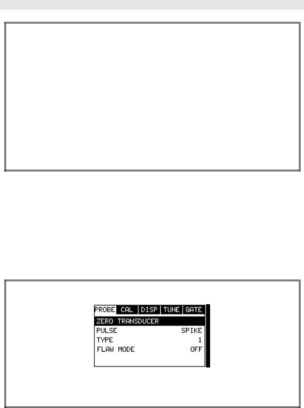
1)Press the MENU key once to activate the menu items tab. Press the MENU key multiple times to tab right and the ESC key multiple times to tab left until the PROBE menu is highlighted and displaying the submenu items.
2
MVX High Performance Thickness Gauge
2)Use the UP and DOWN arrow keys to scroll through the sub menu items until TYPE is highlighted.
3)Press the ENTER key to display the list of transducer types.
4)Press the UP and DOWN arrow keys to scroll through the transducer list until the appropriate type is highlighted.
5)Press the ENTER key to display the confirmation screen.
6)Press the OK key to select the transducer and return to the menu screen, or
ESC to cancel the selecting the transducer.
2.2Probe Zero & Calibration
The next step is to calibrate the MVX to the material and transducer being used. If a sound velocity is not known, the MVX can be calibrated to a known thickness sample. This demo will briefly explain both of these techniques.
In either case, the transducer MUST be zeroed on the probe zero disk (battery cover located on the top of the unit as follows:
Performing a Probe Zero
1)Apply a drop of couplant on the transducer and place the transducer in steady contact with the probe zero disk, and obtain a steady reading.

Dakota Ultrasonics
2)Assuming the probe menu is still displayed from the previous type selection, use the UP and DOWN arrow keys to scroll through the sub menu items until ZERO TRANSDUCER is highlighted.
3)Press the ENTER key to display the confirmation screen.
4)Press the OK key to complete the probe zero function, or ESC key to cancel the probe zero function.
5)Remove the transducer from the probe zero disk, and proceed to the calibration section.
Note: The value that is displayed will change depending on the current velocity
setting in the MVX. Disregard the number that is displayed. It is not
important. What is important is accurately performing the steps outlined above
to insure reliability of the probe zero calculation.
Known Velocity
If the material velocity is known, the user may wish to simply enter the velocity number into the MVX, rather than have the MVX calculate the velocity value on using a know thickness. The steps for entering the velocity are outlined below:
Using a Known Material Velocity
4

MVX High Performance Thickness Gauge
1)Press the MENU key once to activate the menu items tab. Press the MENU key multiple times to tab right and the ESC key multiple times to tab left until the CAL menu is highlighted and displaying the submenu items.
2)Use the UP and DOWN arrow keys to scroll through the sub menu items until VELOCITY is highlighted.
3)Press the ENTER key to display the Digits Edit Box.
4)Press the UP and DOWN arrow keys to scroll the highlighted value.
5)Press the LEFT and RIGHT arrow keys to scroll the digit locations.
6)Repeat steps 4 & 5 until the velocity number is correctly displayed.
7)Press the OK key to set the velocity and return to the menu screen, or ESC to cancel entering the velocity.
8)Finally, press the MEAS key to return to the measurement screen and begin taking readings.
Dakota Ultrasonics
Known Thickness
Sometimes the sound velocity of a material is not known. In this case a sample with a known thickness can be used to determine the sound velocity. It would be very handy to carry a set of mechanical calipers to use in conjunction with the MVX for calibration in the field:
Using a Known Thickness
Note: Be sure that the probe zero procedure has been performed prior to
performing this calibration procedure.
1)Physically measure an exact sample of the material or a location directly on the material to be measured using a set of calipers or a digital micrometer.
2)Apply a drop of couplant on the transducer and place the transducer in steady contact with the sample or actual test material. Be sure that the reading is stable and the repeatability indicator, in the top left corner of the display, is fully lit and stable. Press the MENU key once to activate the menu items tab. Press the MENU key multiple times to tab right and the
ESC key multiple times to tab left until the CAL menu is highlighted and displaying the submenu items.
6
MVX High Performance Thickness Gauge
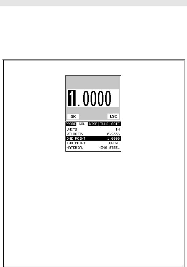
3)Use the UP and DOWN arrow keys to scroll through the sub menu items until ONE POINT is highlighted.
4)Press the ENTER key to display the Digits Edit Box.
5)Press the UP and DOWN arrow keys to scroll the highlighted value.
6)Press the LEFT and RIGHT arrow keys to scroll the digit locations.
7)Repeat steps 5 & 6 until the known thickness value is correctly displayed.
8)Press the OK key to calculate the velocity and return to the menu screen, or
ESC to cancel entering the velocity.
9)Finally, press the MEAS key to return to the measurement screen and begin taking readings.
Note: CHECK YOUR CALIBRATION! Place the transducer back on the calibration point. The thickness reading should now match the known thickness. If the thickness is not correct, repeat the steps above.
Dakota Ultrasonics
Basic Material Type
If the material velocity is unknown, and a sample thickness cannot be taken from the material, the user may opt to choose a basic material type from a list with approximate velocity numbers. It’s important to note that these velocities will not always be an exact representation of the material being tested. Use these values only if a close approximation is acceptable. Follow the steps below to select a basic material type:
Selecting a Basic Material Type
1)Press the MENU key once to activate the menu items tab. Press the MENU key multiple times to tab right and the ESC key multiple times to tab left until the CAL menu is highlighted and displaying the submenu items.
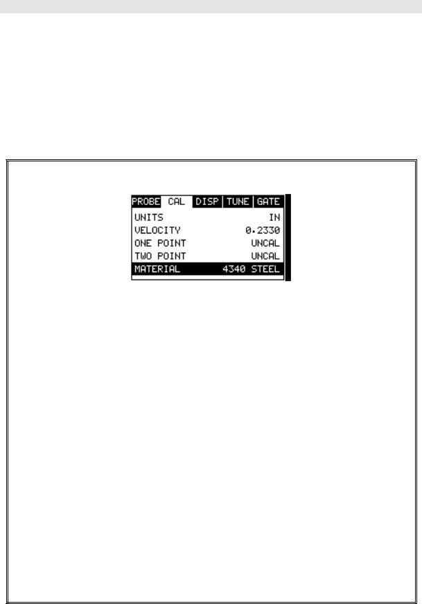
2)Use the UP and DOWN arrow keys to scroll through the sub menu items until MATERIAL is highlighted.
3)Press the ENTER key to display the list of material types.
4)Press the UP and DOWN arrow keys to scroll through the material list until the appropriate material is highlighted.
5)Press the ENTER key to display the confirmation screen.
6)Press the OK key to select the material and return to the menu screen, or
ESC to cancel the material selection.
7)Finally, press the MEAS key to return to the measurement screen and begin taking readings.
8
MVX High Performance Thickness Gauge
2.3 Measure
The MVX is now ready to measure. There are four different measurement view options, each with a specific purpose. The steps below outline how to toggle between the different view mode options:
Selecting the Measurement View Option
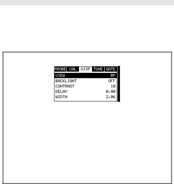
1)Press the MENU key once to activate the menu items tab. Press the MENU key multiple times to tab right and the ESC key multiple times to tab left until the DISP menu is highlighted and displaying the submenu items.
2)Use the UP and DOWN arrow keys to scroll through the sub menu items until VIEW is highlighted.
3)Use the LEFT and RIGHT arrow keys to scroll the view options.
4)Once the view is displayed, press the MEAS key to return to measurement mode.
RF: Is useful to see exactly what the signal looks like directly around the detect point. Use this view only when viewing smaller ranges (zoomed in) around the detection point. This can be done manually by adjusting the delay and width settings.
RECTIFIED (RECT): Displays the entire range being scanned. This screen is useful to “get the big picture” when viewing wide ranges (zoomed out). The point which is triggering the digital thickness reading (called the detect) is displayed as a vertical dashed line.
BSCAN: The Time Based B-Scan provides the user with a cross sectional view of the material being tested. This mode is useful when there is concern regarding the profile of the blind surface. This can also be a useful view when scanning for pits and flaws.
Dakota Ultrasonics
DIGITS: Displays the digital thickness value using a larger font size. This view is useful when the MVX is being used as a basic thickness gauge.
Once the view has been selected according to the application requirements, the delay and width of the screen will potentially need to be adjusted, if the view has been set to RF, RECT, or BSCAN. Use the following steps to adjust these settings directly from the measurement screen as follows:
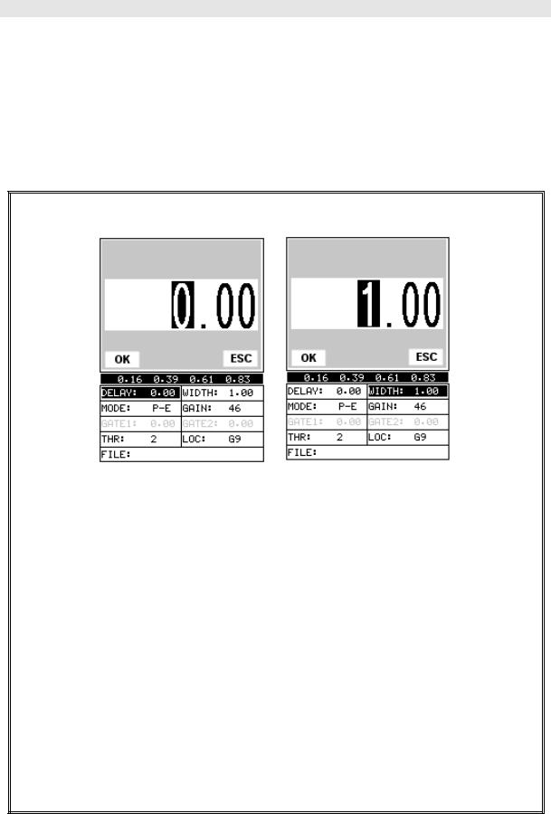
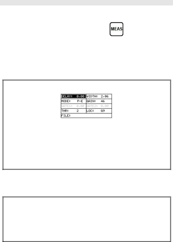
Adjusting the Delay & Width
1)Press the MEAS key once to activate the measure menu items. Press the
MEAS key multiple times to move right and the ESC key multiple times to move left, until the either the DELAY or WIDTH cell is highlighted.
2)Use the UP, DOWN, LEFT, or RIGHT arrow keys to scroll the DELAY and
WIDTH values.
3)Repeat steps 1 & 2 until the range is correctly being displayed.
Alternatively, the DELAY and WIDTH values can be changed using the Digit
Edit Box as follows:
1)Press the MEAS key once to activate measure menu items. Press the
MEAS key multiple times to move right and the ESC key multiple times to move left, until the either the DELAY or WIDTH cell is highlighted.
10

MVX High Performance Thickness Gauge
2)Press the ENTER key to display the digits edit box.
3)Press the UP and DOWN arrow keys to scroll the highlighted value.
4)Press the LEFT and RIGHT arrow keys to scroll the digit locations.
5)Repeat steps 3 & 4 until the DELAY or WIDTH value is correctly displayed.
6)Press the OK key to set the DELAY and WIDTH value and return to the measure screen, or ESC to cancel entering the DELAY or WIDTH value.
7)Finally, press the MEAS key to return to the measurement screen and begin taking readings.
Note: The DELAY & WIDTH can also be adjusted from the menu tab items.
However, using the hot menu keys is the easiest method.
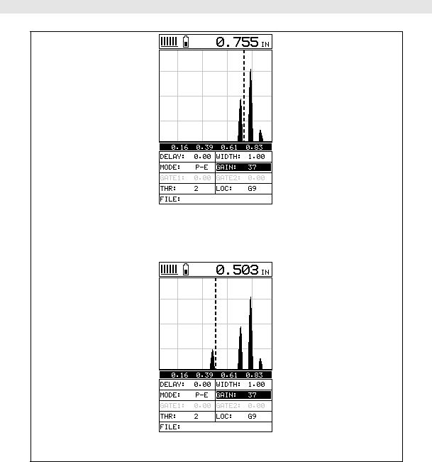
RF |
RECTIFIED |
Dakota Ultrasonics
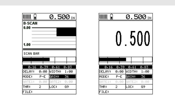
B-SCAN |
DIGITS |
In the upper left corner of each of the mode photos above, is the repeatability indicator. The repeatability indicator is represented by six vertical bars and represents how repeatable the measurements are. In regular measurement mode, the MVX makes 4 measurements a second. In scan mode, the MVX makes 32 measurements a second. When the MVX is idle, only the left vertical bar and the underline will be displayed. However, when the MVX is making a measurement, five or six of the bars should be displayed on the repeatability indicator. If fewer than five bars are showing, the MVX is having difficulty achieving a stable measurement and the thickness value displayed is potentially be unstable. Another thing to note is the vertical broken line in the RF and RECTIFIED photos above. This line represents the actual point of detection. The MVX uses a zero crossing or flank detection method, and presents the actual point of measurement on the display.
12
CHAPTER THREE
KEYBOARD, MENU, & CONNECTOR REFERENCE
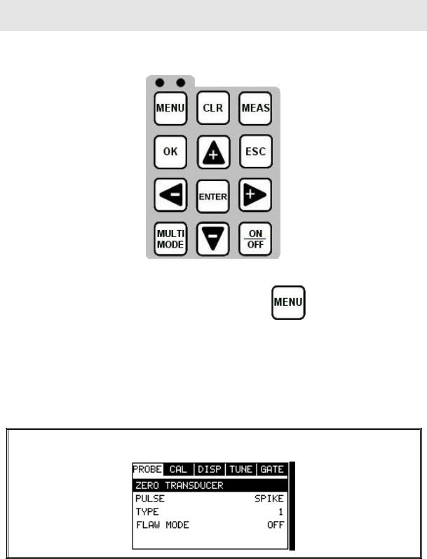
3.1 Menu Key (Operation & Sub Menus )
The Menu key activates the primary menu structure containing 9 menu tab groups. These tab groups then contain sub menu items, or functions. The sub menu items have been organized in tab groups according to how closely they are related to the individual tab group names. Let’s first get familiar with how to move around in these tabs before continuing on to the sub menu functions. This procedure is outlined below:
Activating and Getting Around in the Menu Items
13

Dakota Ultrasonics
1)Press the MENU key once to activate the menu items tab. Press the MENU key multiple times to tab right, and the ESC key multiple times to tab left until the desired tab group is highlighted and displaying the submenu items.
Now that your familiar with activating and moving amongst the tab groups, let’s have a look at how to move around in the sub menu items as follows:
Getting Around in the Sub Menu Items
1)Use the UP and DOWN arrow keys to scroll through the sub menu items until the desired function is highlighted.
2)Depending on which function is highlighted, use the LEFT, RIGHT, and
Enter keys to scroll the options or activate the Digit Edit and List Box
options.
The sections to follow will provide the user with an explanation of the sub menu functions:
3.2 Probe – Menu
Zero: The MVX is zeroed in much the same way that a mechanical micrometer is zeroed. If the MVX is not zeroed correctly, all of the measurements made using the MVX may be in error by some fixed value. Refer to the section on page 35, for an explanation of this important procedure.
Pulse: The MVX has an adjustable pulse width for both high penetration and
resolution applications. The pulse width refers to the duration of time the pulser is on. The options are Spike, Thin , and Wide. Refer to page 73 for a further explanation.
Type: Enables the user to select the type of transducer being used from a chart of transducer types. This provides increased linearity between transducers. Refer to page 31 for a further explanation.
14

MVX High Performance Thickness Gauge
Flaw Mode: Activates the flaw detection mode and view. This feature is for use with single element angle beam transducers and used as a general prove-up flaw inspection mode. Refer to page 107 for a further explanation.
3.3 CAL – Menu
Units: Toggle between English or Metric units. The readout will change from inches to millimeters.
Velocity: Function to calibrate the MVX by setting the velocity to a known material velocity. Refer to page 37 for further info.
One Point: Performs a single point calibration. This option allows the user to automatically calculate the velocity by entering a known sample thickness. Refer to page 39 for further info.
Two Point: Performs a two-point calibration. This option allows the user to automatically calculate the velocity by entering a second known sample thickness. Refer to page 40 for further info.
Material: Select the material velocity from a chart of basic material types, when a known sample thickness, or material velocity cannot be obtained. Refer to page 44 for further info.
3.4 DISP (display) – Menu
View: Selectable RF wave, RECT (rectified) wave, BSCAN (cross section), and DIGITS (large digits) views. Refer to page 46 for further info.
Backlight: Selectable OFF, ON, AUTO, or INVERT backlight option. Contrast: Adjustable display contrast for variable light conditions.
Delay: Provides the user the ability to change where the left side of the display window starts according to thickness, in inches or millimeters. Refer to page 55 for further info.
Width: Provides the user the ability to change the overall size of the viewable measurement area. It functions a lot like a zoom on a camera. Refer to page 52 for further info.

Dakota Ultrasonics
3.5 TUNE – Menu
Gain: Increases or decreases the overall amplitude of the signal. Much like turning the volume up or down on a stereo receiver. Refer to page 57 for further info. AGC: The MVX is equipped with an automatic gain control when operating in echoecho mode only. This is much like turning the volume up or down on a stereo receiver. However, the MVX will automatically control how much the volume is turned up or down. Alternatively, the AGC can be manually controlled using the same procedures as GAIN described above. Refer to page 57 for further info. Threshold: Enables the user to set the sensitivity level of the MVX. The amplitude of the signal must reach and exceed the threshold level before a measurement is detected. Refer to page 60 for further info.
Polarity: The MVX operates on a zero crossing detection principle. This feature toggles which stroke of the cycle the crossing detection uses, either positive or negative. Refer to page 78 for further info.
Rect Waveform: This option provides the user an outlined or filled view option when the display setting is in RECT (rectified) wave mode only. Refer to page 80 for further info.
3.6 GATE – Menu
Measure Mode: Used to select the measurement mode for different application requirements. The modes are P-E (pulse-echo), P-E GT(pulse-echo w/gate), and E- E(echo-echo). Refer to page 24 for further info.
Gate 1: Gates allow the user to view areas or sections of the waveform and ignore others. Gate 1 can be used in both pulse-echo and echo-echo measurement modes. Refer to page 63 for further info.
Gate 2: Gates allow the user to view areas or sections of the waveform and ignore others. Gate 2 is only used in echo-echo measurement mode. Refer to page 67 for further info.
16
MVX High Performance Thickness Gauge
3.7 SETUP – Menu
Open: Displays a list of factory and user defined setups currently stored in memory. These setups can be recalled and used at any time. Refer to page 100 for further info.
Save: Provides the user with the ability to save a custom setup that has been modified or created by the user. Refer to page 102 for further info.
Default Setup: Loads a basic default setup. Use only as a last resort when the setups in the MVX have been corrupted and a computer is not accessible. Refer to page 105 for further info.
3.8 DATA – Menu
New: Allows the user the ability to create a new alpha numeric grid with custom parameters, rows, and columns depending on their application reporting requirements. Refer to page 82 for further info.
Edit: Gives the user the ability to change parameters of grid that have been previously saved. Note: Pre-defined coordinates cannot be changed once they have been created. Refer to page 95 for further info.
Open: This function provides the user with the ability to recall grids that currently exist in memory from a list of grids. Refer to page 97 for further info.
Delete One Grid: This function provides the user with the ability to delete one individual grid from a list of multiple grids previously saved in memory. Refer to page 93 for further info.
Delete All Grids: This function provides the user with the ability to delete all grids currently stored in memory. Refer to page 93 for further info.
3.9 UTIL (utilities) – Menu
Dakota Ultrasonics
Auto Find: Automatically locates the detection point if the measurement is out of the viewable display area. Refer to page 74 for further info.
Scan Mode: This function enables a hi speed scan mode that increases the overall sample rate from the standard 4 measurements a second to 32 measurements a second. Refer to page 75 for further info.
Alarm Status: Toggles alarm mode on or off. Refer to page 76 for further info. Alarm LO Limit: Gives the user the ability to set the LO limit parameter. If the measurement falls below this value, a red light will illuminate and sound the internal beeper. Refer to page 77 for further info.
Alarm HI Limit: Gives the user the ability to set the HI limit parameter. If the measurement exceeds this value, a red light will illuminate and sound the internal beeper. Refer to page 78 for further info.
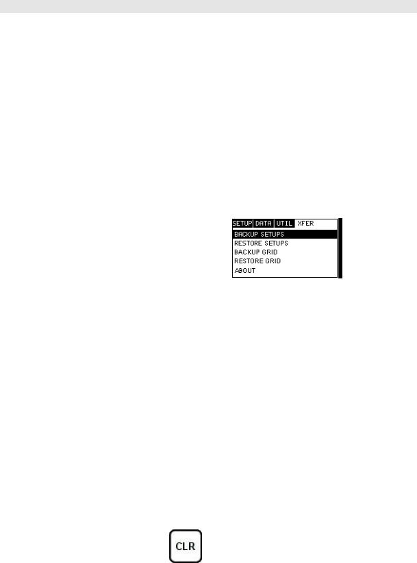
3.10 XFER (transfer) – Menu
Backup Setups: Enables the user the ability to backup the setups currently stored in the MVX to a PC via RS232 port. Refer the help section of the DakView 3 or MVXview software for a complete electronic manual.
Restore Setups: Enables the user the ability to restore the setups currently saved on a PC to an MVX via RS232 port. Refer the help section of the DakView 3 or MVXview software for a complete electronic manual.
Backup Grid: Enables the user the ability to backup grids currently stored in the MVX to a PC via RS232 port. Refer the help section of the DakView 3 or MVXview software for a complete electronic manual.
Restore Grid: Enables the user the ability to restore grids currently saved on a PC to an MVX via RS232 port. Refer the help section of the DakView 3 or MVXview software for a complete electronic manual.
About: Provides the user with Dakota Ultrasonics contact information and the MVX software version. Refer the help section of the DakView 3 or MVXview software for a complete electronic manual.
3.11 CLR (clear) Key
The primary functions of the CLR key, is to clear a measurement from a grid cell location or set obstruct, and backspace in an Alpha Edit Box. If a user has already saved a measurement and waveform to a cell location, use this key to clear the measurement at any time.
18
MVX High Performance Thickness Gauge
3.12 MEAS (measurement mode) Key
The MEAS key puts the MVX into it’s primary mode of operation. In this mode, the user has a complete view of the LCD, as well as control of the Hot Menu Functions. These hot functions provide the user with the ability to make crucial adjustments to the display, waveform settings, and grid storage locations without having to search through the menu and sub menu items. It’s important to first get familiar with moving around in the hot functions as follows:
Getting Around in the Hot Menus
1)Press the MEAS key at any time to return to the primarily measurement mode.
2)Press the MEAS key multiple times to tab right through the menu fields, and the ESC key multiple times to tab left through the menu fields, until the desired hot function is highlighted.
Now that you’re familiar with activating and moving amongst the hot function fields, let’s have a look at how to adjust or change the values of these fields:
Adjusting the Values of the Hot Menus
1)Use the UP, DOWN, LEFT, and RIGHT arrow keys to increase and decrease the values of the hot function fields.
2)Repeat step 1 until the desired value has been achieved.
Dakota Ultrasonics
Alternatively , the delay, width, gain, and threshold hot function fields can be changed using the Digit Edit Box as follows:
1)Press the ENTER key to display the Digits Edit Box.
2)Press the UP and DOWN arrow keys to scroll the highlighted value.
3)Press the LEFT and RIGHT arrow keys to scroll the digit locations.
4)Repeat steps 2 & 3 until the delay, width, gain, or threshold number is correctly displayed.
5)Press the OK key to set and return to the measure screen, or ESC to cancel entering the delay, width, gain, or threshold value.
3.13 OK Key
The primary function of the OK key is confirmation of a change or selection. This key also has a secondary function: pressing the OK key while in the main measurement screen, toggles large digits to be displayed in place of the hot menu items. This will provide the user with a larger digital readout of the measurement, while in RF or RECT display modes.
3.14 ESC Key
The ESC key is used in the MENU, MEAS, and EDIT functions as a back or escape function. This key also has a secondary function: pressing the ESC key, while in the main measurement screen, toggles between all of the possible display view options – RF, RECT, B-SCAN, and DIGITS.
3.15 Arrow Keys
The Arrow Keys are used to navigate through the menus, increase/decrease values, and toggle specific function keys.
20
MVX High Performance Thickness Gauge
3.16 ENTER key
The ENTER key is used in the overall menu selection process, to activate list and edit boxes, and save measurements to grid locations.
3.17 MULTI MODE Key
The MULTI MODE key toggles the measurement mode of the MVX, from pulse-echo (flaw mode), to echo-echo (thru paint) mode. This is a q uick automatic preset mode that enables the user to change modes without having to manually adjust the view and gate parameters. Both modes have been configured for use with any transducer type selected.
3.18 ON/OFF Key
The ON/OFF key simply powers the unit either ON or OFF. Note: Unit will automatically power off when idle for 5 minutes. All current settings are saved prior to powering off.
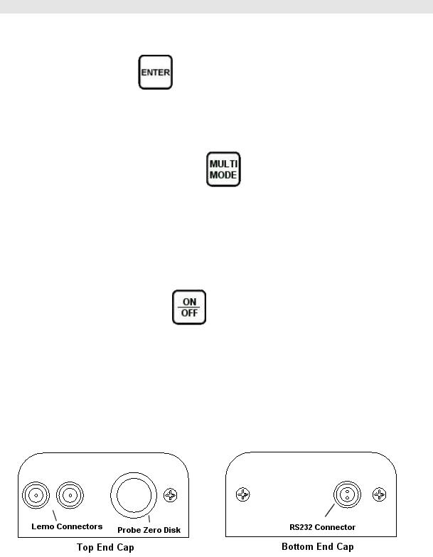
3.19 Top & Bottom End Caps
The top & bottom end panels are where all connections are made to the MVX. The diagram above shows the layout and description of the connectors:

Dakota Ultrasonics
Transducer Connectors
Refer to Diagram: The transducer connectors, and battery cover/probe zero disk are located on the MVX’s top end cap. The transducer connectors are of type Lemo “00”. Note: There is no polarity associated with connecting the transducer to the
MVX.
Probe Zero Disk & Battery Cover
Refer to Diagram: The Battery cover is the large round disk shown in the diagram. Note: This same disk is also used as a probe zero disk. Simply remove the cover when replacing the batteries (3 AA cells). When performing a probe zero function, simply place the transducer on disk making firm contact. Important: Be sure to follow the polarity labels located on the back label of the MVX. Note: Rechargeable batteries can be used, however they must be recharged outside of the unit in a stand alone battery charger.
RS-232 Connector
Refer to Diagram: The RS-232 connector, located on the bottom end cap, is a 2 pin female Lemo connector. It is designed to connect directly from the MVX to a standard AT serial port on a PC. The cable supplied with the MVX is a Lemo to 9 pin serial cable. Note: This connector is also used to upgrade the MVX with the latest version of firmware.
22

CHAPTER FOUR
PRINCIPALS OF ULTRASONIC MEASUREMENT
4.1 Time versus thickness relationship
Ultrasonic thickness measurements depend on measuring the length of time it takes for sound to travel through the material being tested. The ratio of the thickness versus the time is known as the sound velocity. In order to make accurate measurements, a sound velocity must be determined and entered into the instrument.
The accuracy of a thickness measurement therefore depends on having a consistent sound velocity. Some materials are not as consistent as others and accuracy will be marginal. For example, some cast materials are very granular and porous and as a result have inconsistent sound velocities.
While there are many different ultrasonic techniques to measure thickness, which will be discussed below, all of them rely on using the sound velocity to convert from time to thickness.
4.2 Suitability of materials
Ultrasonic thickness measurements rely on passing a sound wave through the material being measured. Not all materials are good at transmitting sound. Ultrasonic thickness measurement is practical in a wide variety of materials including metals, plastics, and glass. Materials that are difficult include some cast materials, concrete, wood, fiberglass, and some rubber.
4.3 Range of measurement and accuracy
The overall measurement capabilities, based on the wide variety of materials, is determined by the consistency of the material being measured
The range of thickness that can be measured ultrasonically depends on the material as well as the technique being used and the type of transducer. Thickness measurements can be made from a minimum of 0.010 inch to 9.999” in steel. However, the maximum attainable thickness is much less for more attenuative materials (materials that absorb sound).
Accuracy, is determined by how consistent the sound velocity is through the sound path being measured and, is a function of the overall thickness of the material. For example, the velocity in steel is typically within 0.5% while the velocity in cast iron can vary by 4%.
4.4 Couplant
All ultrasonic applications require some medium to couple the sound from the transducer to the test piece. Typically a high viscosity liquid is used as the medium. The sound frequencies used in ultrasonic thickness measurement do not travel
23

Dakota Ultrasonics
through air efficiently. By using a liquid couplant between the transducer and test piece the amount of ultrasound entering the test piece is much greater.
4.5 Temperature
Temperature has an effect on sound velocity. The higher the temperature, the slower sound travels in a material. High temperatures can also damage transducers and present a problem for various liquid couplants.
Since the sound velocity varies with temperature it is important to calibrate at the same temperature as the material being measured.
Normal temperature range
Most standard transducers will operate from 0°F to 180°F.
High temperature measurements
Special transducers and couplants are available for temperatures above 180°F up to 650°F with intermittent contact. It is necessary to cool the transducer, by submerging the transducer in water between readings, when measuring high temperatures.
Modes and temperature errors
In addition to errors caused by velocity changing with temperature, some modes (measurement techniques) are affected more than others. For example, dual element mode has larger errors due to changes in temperature of the delay line. However, multi-echo techniques help to minimize these errors.
4.6 Measurement Modes
In this section we will discuss the different measurements modes the MVX is capable of operating in, the transducers required, and the reasons for using specific modes:
Pulse-Echo Mode (Flaw & Pit detection)
Pulse-echo mode measures from the initial pulse (sometimes referred to as an artificial zero) to the first echo (reflection). In this mode, the transducer is placed on a reference disk, located on top of the MVX, and a key is pressed to establish a zero point for the particular transducer.
In this mode errors result from surface coatings and temperature variations.
Since pulse-echo only requires one reflection, it is the most sensitive mode for measuring weak reflections (flaws) typically found when measuring heavily corroded metals.
V-Path Correction
Dual element delay line transducers have two piezoelectric ele ments mounted at an angle on one end of the delay line. One element is used for transmitting sound, while the other element only receives sound. The two elements and their delay lines are packaged in a single housing but acoustically isolated from each other with a sound
24

MVX High Performance Thickness Gauge
barrier. This allows the transducer the ability to achieve very high sensitivity for detecting small defects. Also, the surface of the test material does not have to be as flat in order to obtain good measurements.
Dual element transducers are normally used in pulse-echo mode for finding defects, and in echo-echo mode for through coating measurements.
Dual element delay line transducers are usable over a range of 0.025 inches to 20 inches depending on the material, frequency, and diameter.
A limitation of dual element delay-line transducers is the V shaped sound path. Because the sound travels from one element to another, the time versus thickness relationship is non-linear. Therefore, a correction table in the instruments software is used to compensate for this error.
Dual Element Transducer showing V-path of signal
Echo-Echo Mode
The echo-echo mode measures between two reflections. This technique is commonly used to eliminate errors from surface coatings and also to make measurements in multiple layered materials. The disadvantage is that two echoes are needed which requires a much stronger echo (reflection).
Dual Element Transducer in Echo to Echo mode
Searching for small defects
Dual element delay line transducers are especially useful in searching for small defects. In the pulse-echo mode with high amplifier gain, very small defects can be measured. The A-Scan display of the MVX can be used to see the defect and optimize the transducer placement.
Sometimes a grain particle or air bubble will cause a reflection. Without the A-Scan display it is impossible to know if this is a thin area or just a harmless defect. The A- Scan allows the user to see the backwall as well as the defect similar to a flaw detector.
Dakota Ultrasonics
Waveform showing echo from corroded backwall
Waveform showing flaw with solid backwall
26
 Loading...