

Page 1
OPERATION MANUAL
DAKOTA ULTRASONICS
PPRR--88VV
Sonic Tester
P/N P-158-0002 Rev 1.10, January 2008
Page 2

Page 3

CHAPTER ONE INTRODUCTION.......................................................................1
CHAPTER TWO QUICK STARTUP GUIDE........................................................2
CHAPTER THREE KEY BOARD, MENU, & CONNECTOR REFERENCE.......12
CHAPTER FOUR PRINCIPALS OF ULTRASONIC ME ASUREMENT .............21
CHAPTER FIVE SELECTING THE MEASUREMENT MODE..........................25
CHAPTER SIX MAKING MEASUREMENTS.....................................................28
CHAPTER SEVEN USING THE DIGITS & B-SCAN DISPLAYS ......................41
CHAPTER EIGHT THRU PAINT MEASUREMENT TECHNIQUE....................55
CHAPTER NINE ADDITIO NAL FEATURES OF THE PR-8V............................56
CHAPTER TEN DATA STORAGE – SETUP, EDIT, & VIEW GRIDS...............60
CHAPTER ELEVEN SETUPS – CREATE, STORE, EDIT, & RECALL............79
CHAPTER TWELVE USING THE UTILITY SOFTWARE..................................85
APPENDIX A - VELOCITY TABLE .....................................................................86
APPENDIX B - SETUP LIBRARY.......................................................................88
Page 4

Page 5

CHAPTER ONE
INTRODUCTION
The Dakota Ultrasonics model PR-8V is a digital sonic tester with a ton of features
geared specifically towards the racing industry. Based on the same operating
principles as SONAR, the PR-8V is capable of measuring the thickness of various
materials with accuracy as high as ± 0.001 inches, or ± 0.01 millimeters. The
principle advantage of ultrasonic measurement over traditional methods is that
ultrasonic measurements can be performed with access to only one side of the
material being measured.
Dakota Ultrasonics maintains a customer support resource in order to assist users
with questions or difficulties not covered in this manual. Customer support may be
reached at any of the following:
• Dakota Ultrasonics Corporation,
1500 Green Hills Road, #107 Scotts Valley, CA
95066 USA
• Telephone: (831) 431- 9722
• Facsimile: (831) 431-9723
• www.dakotaultrasonics.com
1.1 Disclaimer
Inherent in ultrasonic thickness measurement is the possibility that the instrument will
use the second rather than the first echo from the back surface of the material being
measured. This may result in a thickness reading that is TWICE what it should be.
Responsibility for proper use of the instrument and recognition of this phenomenon
rest solely with the user of the instrument.
1
Page 6
CHAPTER TWO
QUICK STARTUP GUIDE
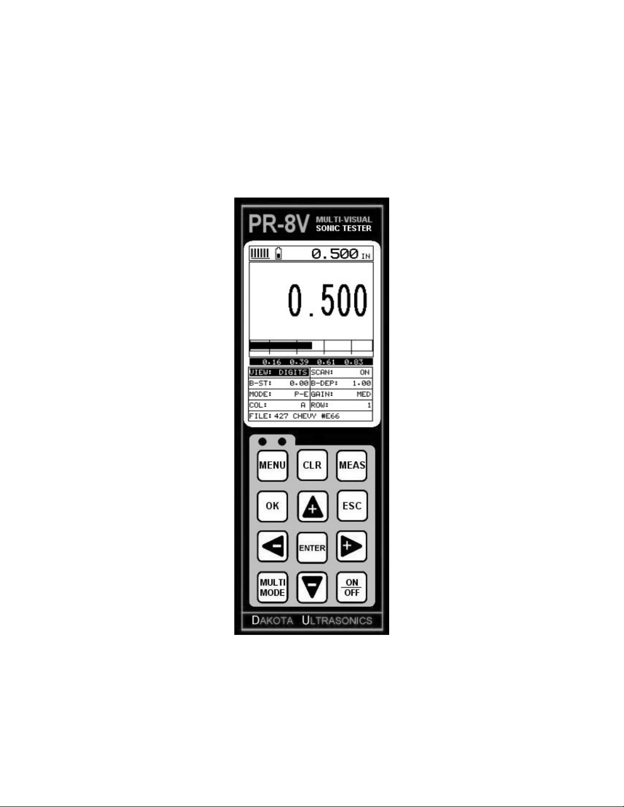
Turn the PR-8V on and off using the switch located on the bottom right corner of the
keypad. When PR-8V is initially turned on, a flash logo and blinking lights will be
displayed prior to entering into the main measurement screen. Note: This section is
primarily written as a basic startup guide only.
2.1 Selecting The Transducer Type
The first step in using the PR-8V is to select the transducer type according to
frequency and diameter. By selecting the transducer type from a predefined list, the
PR-8V can recall specific properties about the transducer. Note: Once the
transducer has been selected, the PR-8V will store and recall this transducer type
every time the PR-8V is powered on/off. The type will only change if the user
physically selects another transducer type from the list, or selects a previously saved
setup. Therefore, if you have previously gone through this section and selected the
transducer you are using, proceed to the next section. Use the following steps to
select your transducer type:
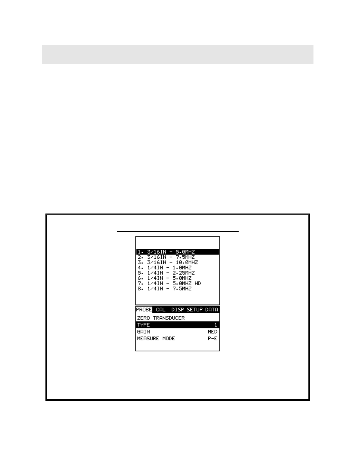
Selecting the Transducer Type
1) Press the MENU key once to activate the menu items tab. Press the MENU
key multiple times to tab right and the ESC key multiple times to tab left until
the PROBE menu is highlighted and displaying the submenu items.
2
Page 7
PR-8V High Performance Thickness Gauge
2) Use the UP and DOWN arrow keys to scroll through the sub menu items
until TYPE is highlighted.
3) Press the ENTER key to display the list of transducer types.
4) Press the UP and DOWN arrow keys to scroll through the transducer list
until the appropriate type is highlighted.
5) Press the ENTER key to display the confirmation screen.
6) Press the OK key to sel ect the transducer and return to the menu screen, or
ESC to cancel the selecting the transducer.
2.2 Probe Zero & Calibration
The next step is to calibrate the PR-8V to the material and transducer being used. If
the materials sound velocity is unknown, the PR-8V can be calibrated to a known
thickness sample. This demo will briefly explain both of these techniques.
In either case, the transducer MUST be zeroed on the probe zero disk (battery cover)
located on the top of the unit as follows:
Performing a Probe Zero
1) Apply a drop of couplant on the transducer and place the transducer in
steady contact with the probe zero disk, and obtain a steady reading.
3
Page 8
Dakota Ultrasonics
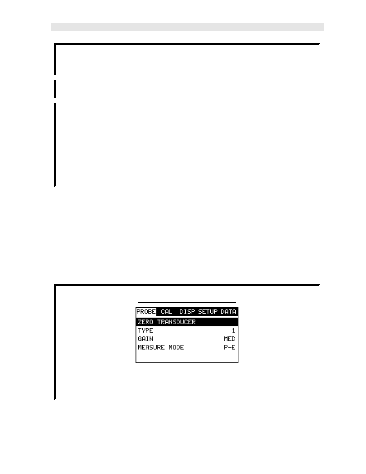
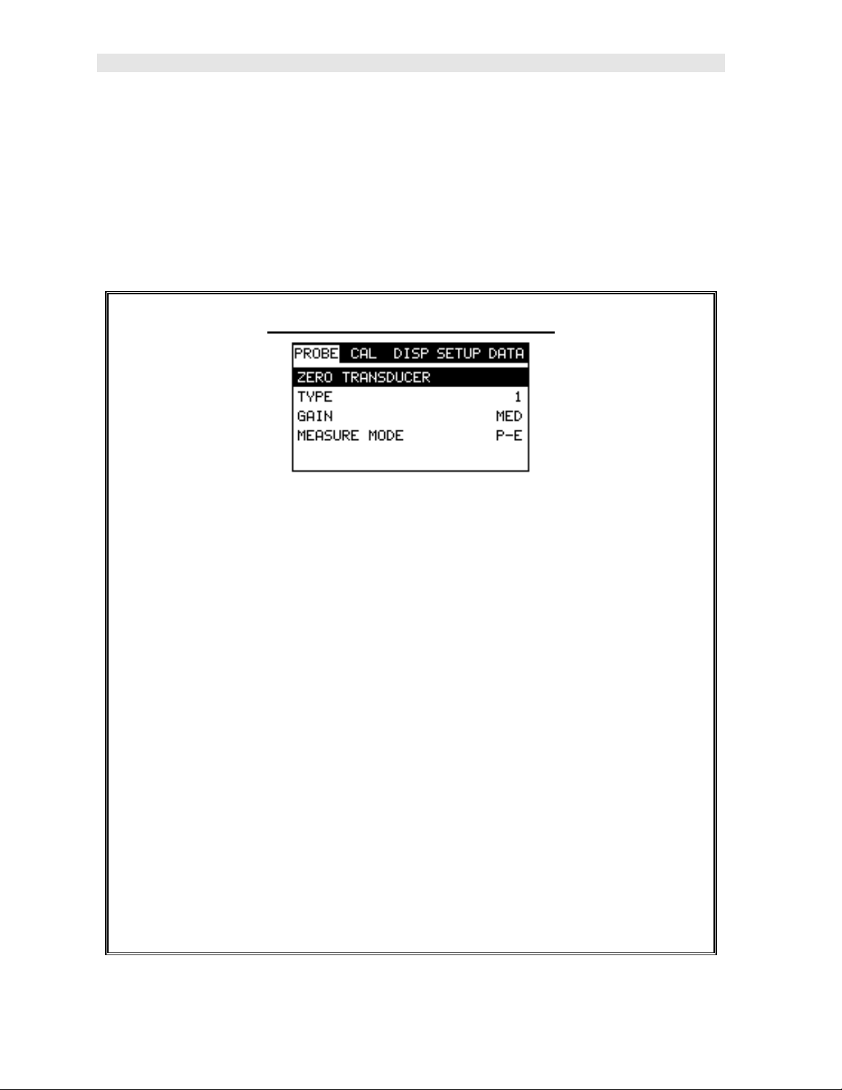
2) Assuming the probe menu is still displayed from the previous type selection,
use the UP and DOWN arrow keys to scroll through the sub menu items
until ZERO TRANSDUCER is highlighted.
3) Press the ENTER key to display the confirmation screen.
4) Press the OK key to complete the probe zero function, or ESC key to cancel
the probe zero function.
5) Remove the transducer from the probe zero disk, and proceed to the
calibration section.
Note: The value that is displayed will change depending on the current velocity
setting in the PR-8V. Disregard the number that is displayed. It is not
important. What is important is accurately performing the steps outlined above
to insure reliability of the probe zero calculation.
Known Velocity
If the material velocity is known, the user may wish to simply enter the velocity
number into the PR-8V, rather than have the PR-8V calculate the velocity value on
using a know thickness. The steps for entering the velocity are outlined below:
Using a Known Material Velocity
4
Page 9
PR-8V High Performance Thickness Gauge
1) Press the MENU key once to activate the menu items tab. Press the MENU
key multiple times to tab right and the ESC key multiple times to tab left until
the CAL menu is highlighted and displaying the submenu items.
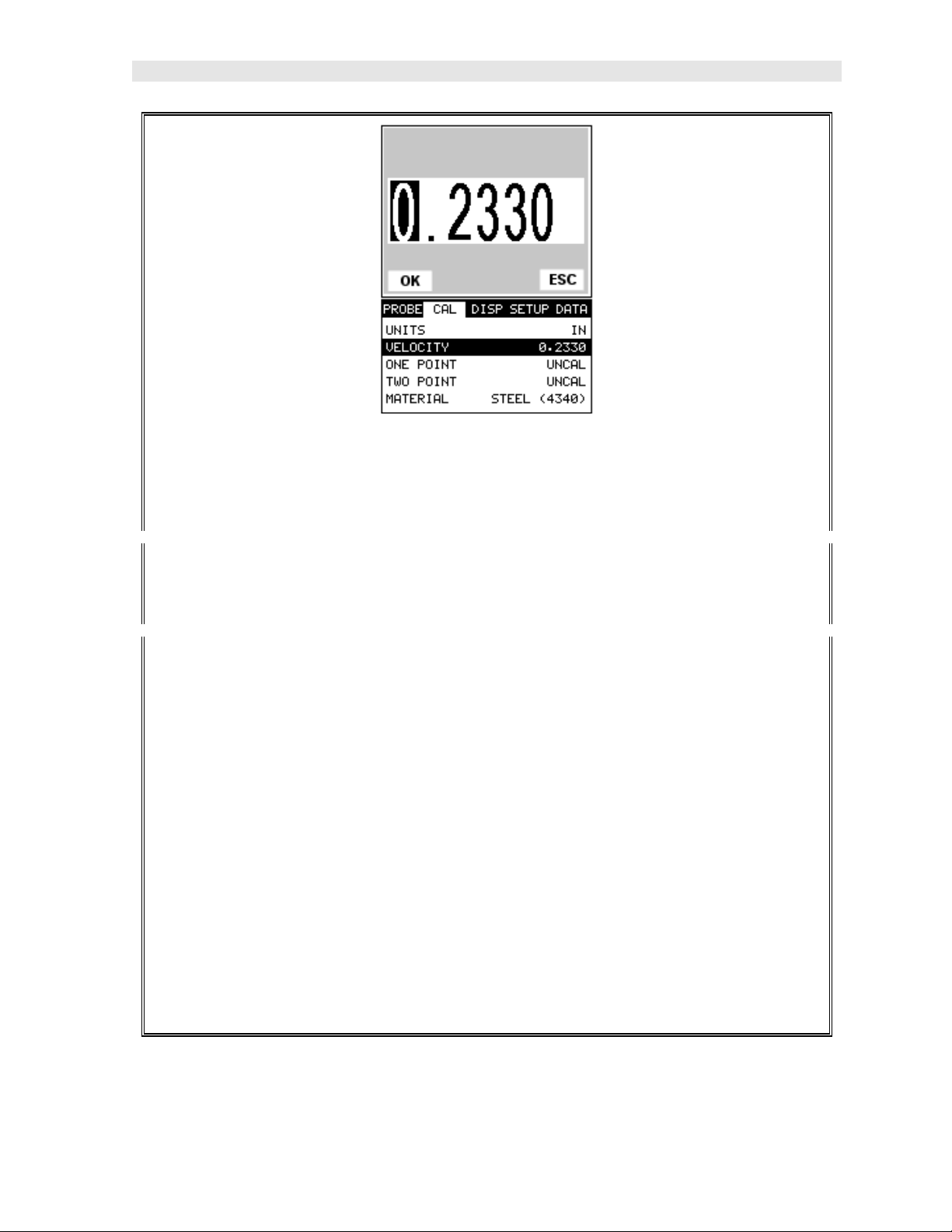
2) Use the UP and DOWN arrow keys to scroll through the sub menu items
until VELOCITY is highlighted.
3) Press the ENTER key to display the Digits Edit Box.
4) Press the UP and DOWN arrow keys to scroll the highlighted value.
5) Press the LEFT and RIGHT arrow keys to scroll the digit locations.
6) Repeat steps 4 & 5 until the velocity number is correctly displayed.
7) Press the OK key to set the velocity and return to the menu screen, or ESC
to cancel entering the velocity.
8) Finally, press the MEAS key to return to the measurement screen and begin
taking readings.
5
Page 10
Dakota Ultrasonics
Known Thickness
Sometimes the sound velocity of a material is unknown. In this case a sample with a
known thickness can be used to determine the sound velocity. It would be very
handy to carry a set of mechanical calipers to use in conjunction with the PR-8V for
calibration in the field:
Using a Known Thickness
Note: Be sure that the probe zero procedure has been performed prior to
performing this calibration procedure.
1) Physically measure an exact sample of the material or a location directly on
the material to be measured using a set of calipers or a digital micrometer.
2) Apply a drop of couplant on the transducer and place the transducer in
steady contact with the sample or actual test material. Be sure that the
reading is stable and the repeatability indicator, in the top left corner of the
display, is fully lit and stable. Press the MENU key once to activate the
menu items tab. Press the MENU key multiple times to tab right and the
ESC key multiple times to tab left until the CAL menu is highlighted and
displaying the submenu items.
6
Page 11

PR-8V High Performance Thickness Gauge
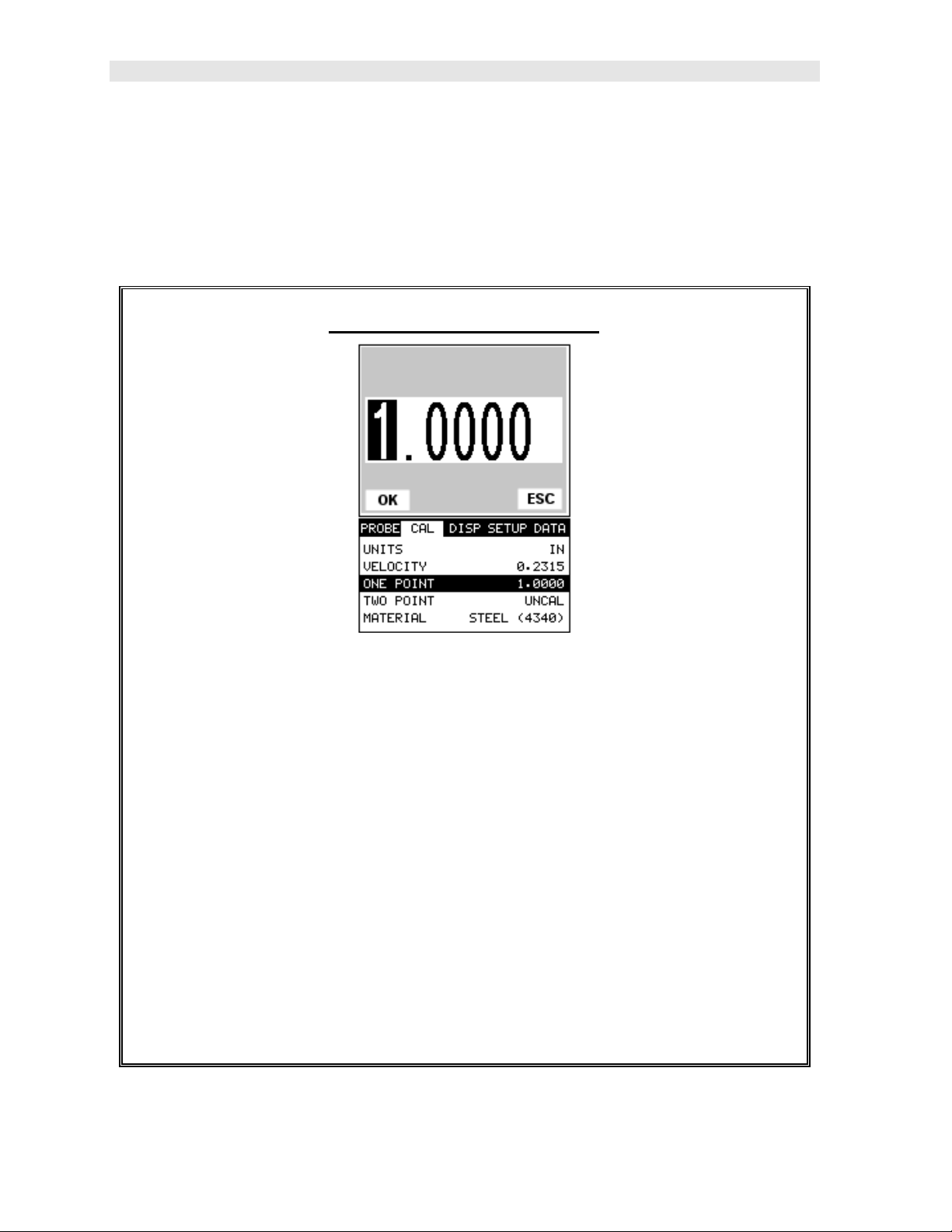
3) Use the UP and DOWN arrow keys to scroll through the sub menu items
until ONE POINT is highlighted.
4) Press the ENTER key to display the Digits Edit Box.
5) Press the UP and DOWN arrow keys to scroll the highlighted value.
6) Press the LEFT and RIGHT arrow keys to scroll the digit locations.
7) Repeat steps 5 & 6 until the known thickness value is correctly displayed.
8) Press the OK key to calculate the velocity and return to the menu screen, or
ESC to cancel entering the velocity.
9) Finally, press the MEAS key to return to the measurement screen and begin
taking readings.
Note: CHECK YOUR CALIBRATI ON! Place the transducer back on the
calibration point. The thickness reading should now match the known
thickness. If the thickness is incorrect, repeat the steps above.
7
Page 12
Dakota Ultrasonics
Basic Material Type
If the material velocity is unknown, and a sample thickness cannot be taken from the
material, the user may opt to choose a basic material type from a list with
approximate velocity numbers. It’s important to note that these velocities will not
always be an exact representation of the material being tested. Use th ese values
only if a close approximation is acceptable. Follow the steps below to select a basic
material type:
Selecting a Basic Material Type
1) Press the MENU key once to activate the menu items tab. Press the MENU
key multiple times to tab right and the ESC key multiple times to tab left until
the CAL menu is highlighted and displaying the submenu items.
2) Use the UP and DOWN arrow keys to scroll through the sub menu items
until MATERIAL is highlighted.
3) Press the ENTER key to display the list of material types.
4) Press the UP and DOWN arrow keys to scroll through the material list until
the appropriate material is highlighted.
5) Press the ENTER key to display the confirmation screen.
6) Press the OK key to select the material and return to the menu screen, or
ESC to cancel the material selection.
7) Finally, press the MEAS key to return to the measurement screen and begin
taking readings.
8
Page 13
PR-8V High Performance Thickness Gauge
2.3 Measure
The PR-8V is now ready to measure. There are two different measurement view
options, each with a specific purpose – Digits & B-Scan. The steps below outline
how to toggle between the different view mode options:
Selecting the Measurement View Option
1) Press the MENU key once to activate the menu items tab. Press the MENU
key multiple times to tab right and the ESC key multiple times to tab left until
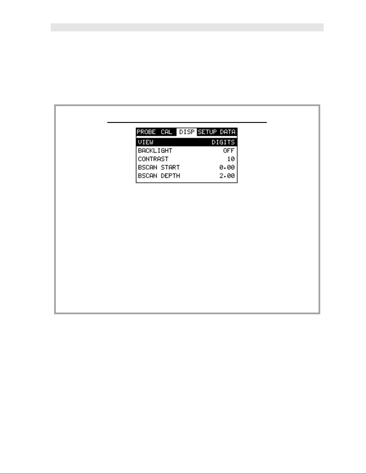
the DISP menu is highlighted and displaying the submenu items.
2) Use the UP and DOWN arrow keys to scroll through the sub menu items
until VIEW is highlighted.
3) Use the LEFT and RIGHT arrow keys to scroll the view options.
4) Once the view is displayed, press the MEAS key to return to measurement
mode.
DIGITS: Displays the digital thickness value using a larger font size. This view is
useful when the PR -8V is being used as a basic thickness gauge.
BSCAN: The Time Based B-Scan provides the user with a cross sectional view of
the material being tested. This mode is useful when there is concern regarding the
profile of the blind surface. This can also be a useful view when scanning for pits and
flaws.
Once the view has been selected according to the application requirements, the
delay and width of the screen will potentially need to be adjusted, if the view has
9
Page 14
Dakota Ultrasonics
been set to BSCAN. Use the following steps to adjust these settings directly from the
measurement screen as follows:
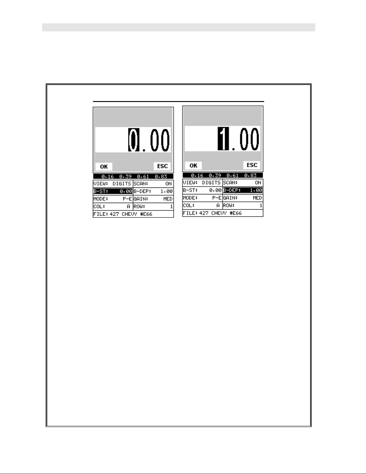
Adjusting the Start (B-ST) & Depth (B-DEP)
1) Press the MEAS key once to activate the measure menu items. Press the
MEAS key multiple times to move right and the ESC key multiple times to
move left, until the either the B-ST or B-DEP cell is highligh ted.
2) Use the UP, DOWN, LEFT, or RIGHT arrow keys to scroll the B-ST and B-
DEP values.
3) Repeat steps 1 & 2 until the range is correctly being displayed.
Alternatively, the B-ST and B-DEP values can be changed using the Digit Edit
Box as follows:
1) Press the MEAS key once to activate measure menu items. Press the
MEAS key multiple times to move right and the ESC key multiple times to
move left, until the either the B-ST or B-DEP cell is highlighted.
2) Press the ENTER key to display the digits edit box.
3) Press the UP and DOWN arrow keys to scroll the highlighted value.
10
Page 15
PR-8V High Performance Thickness Gauge
4) Press the LEFT and RIGHT arrow keys to scroll the digit locations.
5) Repeat steps 3 & 4 until the B-ST or B-DEP value is correctly displayed.
6) Press the OK key to set the B-ST and B-DEP value and return to the
measure screen, or ESC to cancel entering the B-ST or B-DEP value.
7) Finally, press the MEAS key to return to the measurement screen and begin
taking readings.
Note: The B-ST & B-DEP can also be adjusted from the menu tab items.
However, using the hot menu keys is the easiest method.
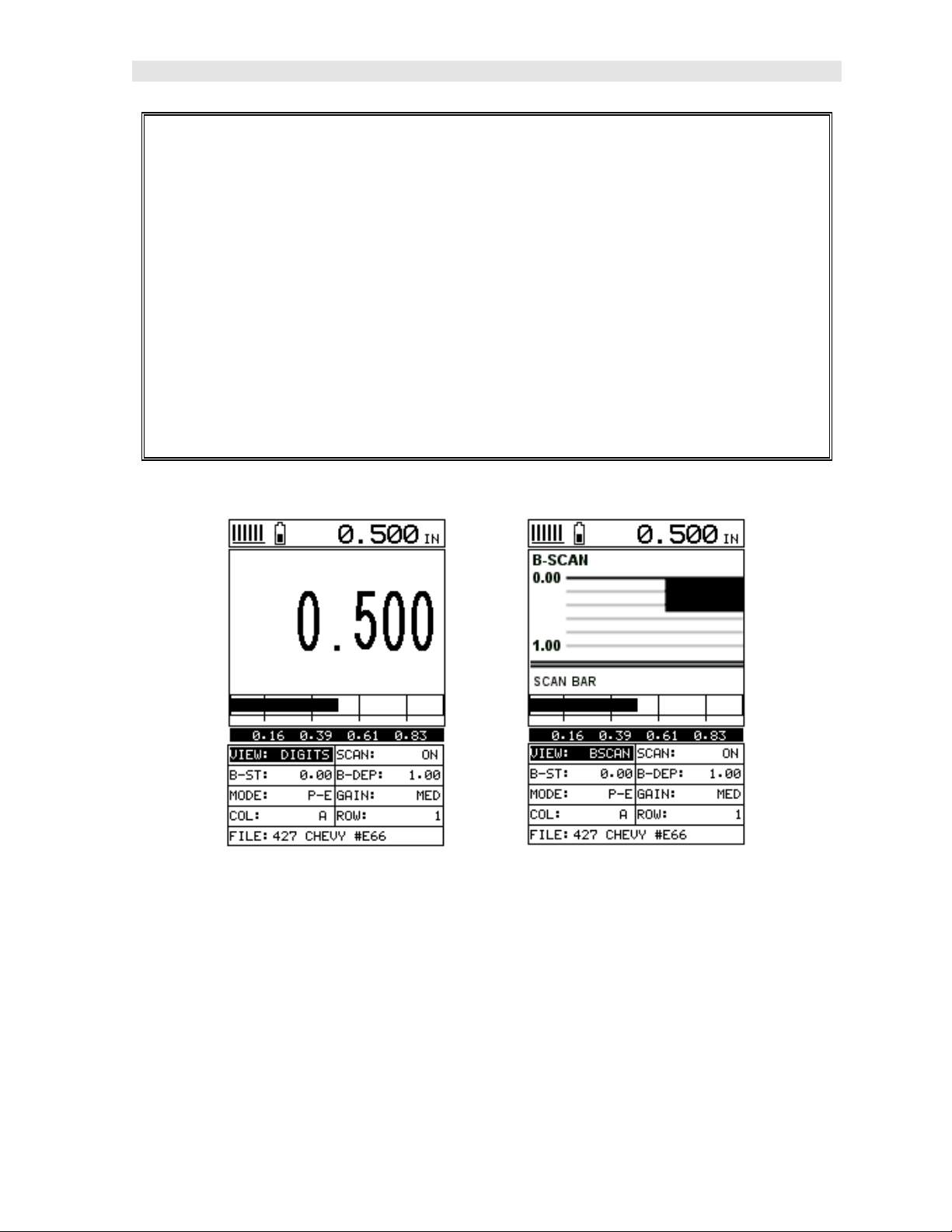
B-SCAN DIGITS
In the upper left corner of each of the mode photos above, is the repeatability
indicator. The repeatability indicator is represented by six vertical bars and
represents how repeatable the measurements are. In regular measurement mode,
the PR-8V makes 4 measurements a second. In scan mode, the PR-8V makes 32
measurements a second. When the PR-8V is idle, only the left vertical bar and the
underline will be displayed. However, when the PR-8V is making a measurement,
five or six of the bars should be displayed on the repeatability indicator. If fewer than
five bars are showing, the PR-8V is having difficulty achieving a stable measurement
and the thickness value displayed is potentially be unstable.
11
Page 16
CHAPTER THREE
KEYBOARD, MENU, & CONNECTOR REFERENCE
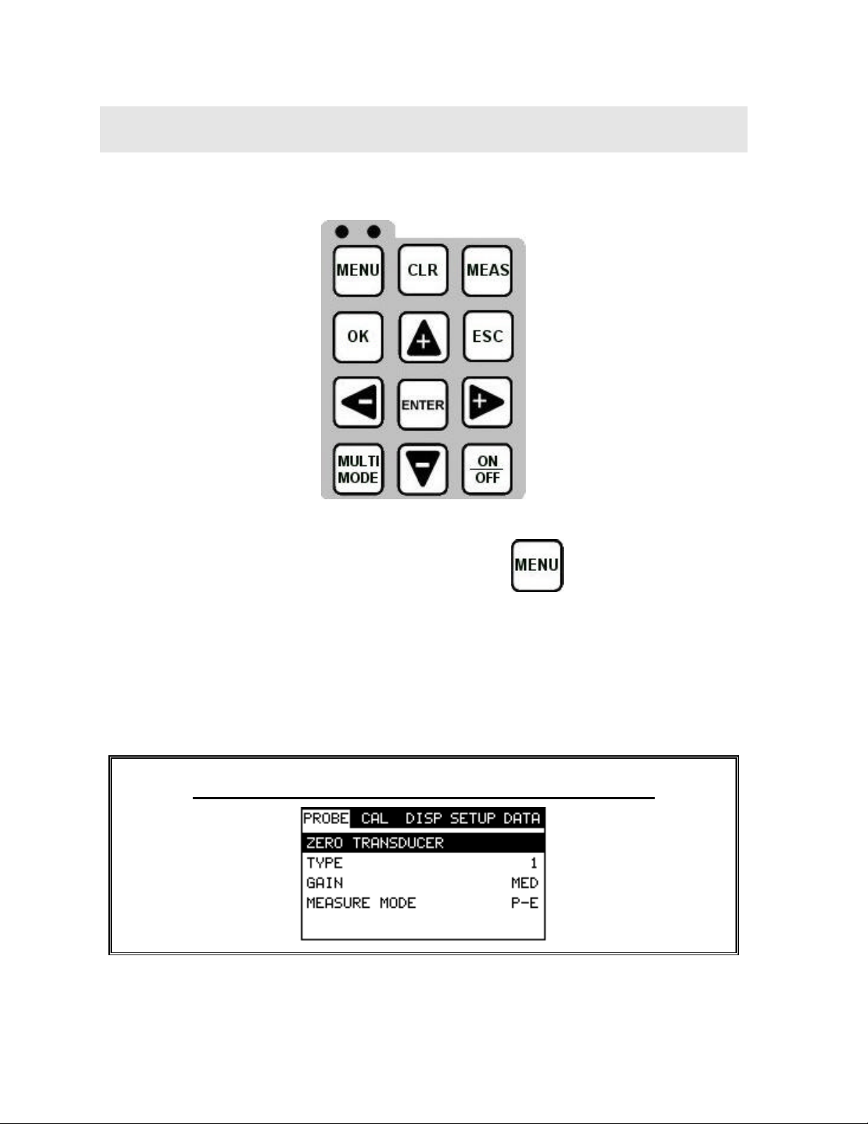
3.1 Menu Key (Operation & Sub Menus )
The Menu key activates the primary menu structure containing 9 menu tab groups.
These tab groups then contain sub menu items, or function s. The sub menu items
have been organized in tab groups according to how closely they are related to the
individual tab group names. Let’s first get familiar with how to move around in these
tabs before continuing on to the sub menu functions. This procedure is outlined
below:
Activating and Getting Around in the Menu Items
12
Page 17
PR-8V High Performance Thickness Gauge
1) Press the MENU key once to activate the menu items tab. Press the MENU
key multiple times to tab right, and the ESC key multiple times to tab left
until the desired tab group is highlighted and displaying the submenu items.
Now that your familiar with activating and moving amongst the tab groups, let’s have
a look at how to move around in the sub menu items as follows:
Getting Around in the Sub Menu Items
1) Use the UP and DOWN arrow keys to scroll through the sub menu items
until the desired function is highlighted.
2) Depending on which function is highlighted, use the LEFT, RIGHT, and
Enter keys to scroll the options or activate the Digit Edit and List Box
options.
The sections to follow will provide the user with an explanation of the sub menu
functions:
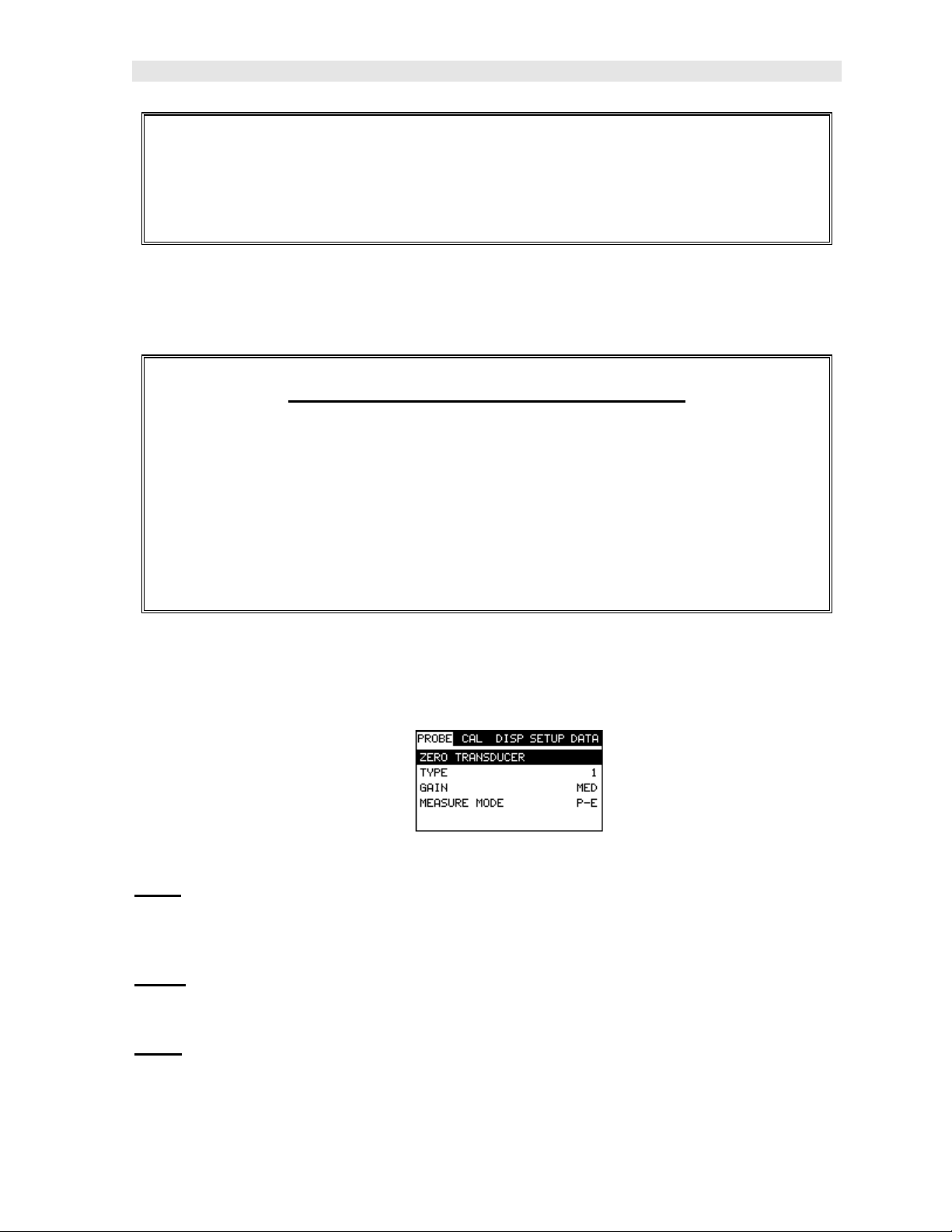
3.2 Probe – Menu
Zero: The PR-8V is zeroed in much the same way that a mechanical micrometer is
zeroed. If the PR-8V is not zeroed correctly, all of the measurements made using the
PR-8V may be in error by some fixed value. Refer to the section on page 32, for an
explanation of this important procedure.
Type: Enables the user to select the type of transducer being used from a chart of
transducer types. This provides increased linearity between transducers. Refer to
page 28 for a further explanation.
Gain: Increases or decreases the overall amplitude of the signal. Much like turning
the volume up or down on a stereo receiver. Refer to page 51 for further info.
13
Page 18
Dakota Ultrasonics
AGC: The PR-8V is equipped with an automatic gain control when operating in
echo-echo mode only. This is much like turning the volume up or down on a stereo
receiver. However, the PR-8V will automatically control how much the volume is
turned up or down. Alternatively, the AGC can be manually controlled using the
same procedures as GAIN described above. Refer to page 51 for further info.
Measure Mode: Used to select the measurement mode for different application
requirements. The modes are P-E (pulse-echo) and E-E(echo-echo). Refer to page
22 for further info.
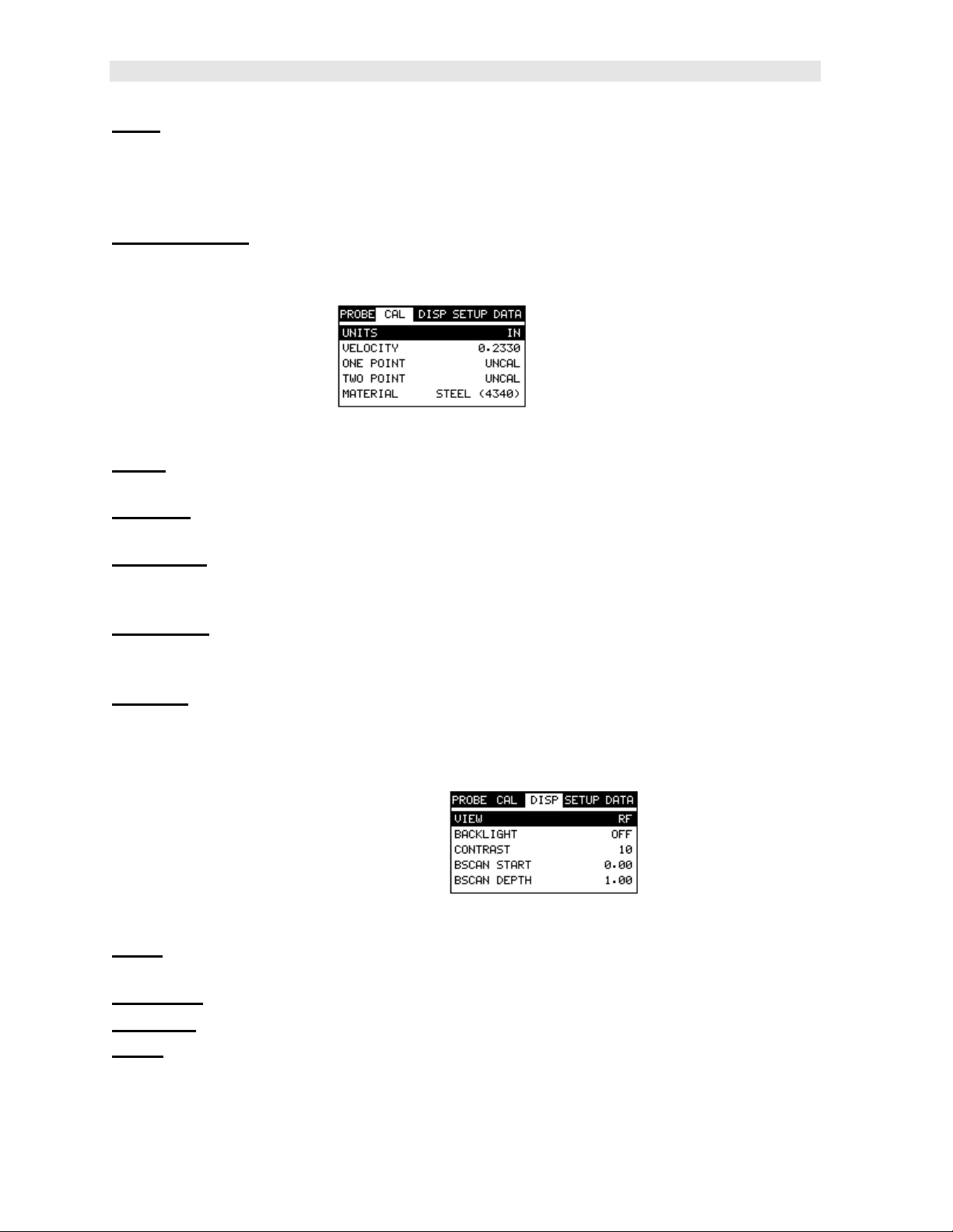
3.3 CAL – Menu
Units: Toggle between English or Metric units. The readout will change from inches
to millimeters.
Velocity: Function to calibrate the PR-8V by setting the velocity to a known material
velocity. Refer to page 34 for further info.
One Point: Performs a single point calibration. This option allows the user to
automatically calculate the velocity by entering a known sample thickness. Refer to
page 36 for further info.
Two Point: Performs a two-point calibration. This option allows the user to
automatically calculate the velocity by entering a second known sample thickness.
Refer to page 37 for further info.
Material: Select the material velocity from a chart of basic material types, when a
known sample thickness, or material velocity cannot be obtained. Refer to page 40
for further info.
3.4 DISP (display) – Menu
View: Selectable RF wave, RECT (rectified) wave, BSCAN (cross section), and
DIGITS (large digits) views. Refer to page 42 for further info.
Backlight: Selectable OFF, ON, AUTO, or INVERT backlight option.
Contrast: Adjustable display contrast for variable light conditions.
B-ST: Provides the user the ability to change the start position of the B-SCAN view.
Refer to page 49 for further info.
14
Page 19
PR-8V High Performance Thickness Gauge
B-DEP: Provides the user the ability to change the overall depth of the viewable
measurement area. It functions a lot like a zoom on a camera. Refer to page 46 for
further info.
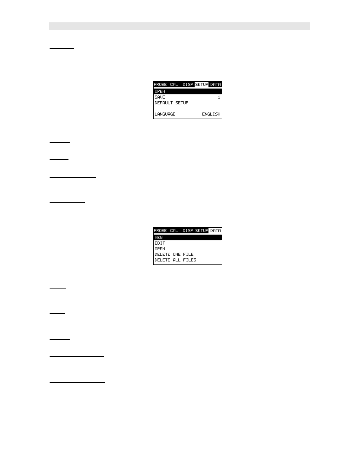
3.5 SETUP – Menu
Open: Displays a list of factory and user defined setups currently stored in memory.
These setups can be recalled and used at any time. Refer to page 79 for further info.
Save: Provides the user with the ability to save a custom setup that has been
modified or created by the user. Refer to page 81 for further info.
Default Setup: Loads a basic default setup. Use only as a last resort when the
setups in the PR-8V have been corrupted and a computer is not accessible. Refer to
page 83 for further info.
Language: Provides the user the ability to select different languages for the PR-8V.
Refer to page 83 for further info.
3.6 DATA – Menu
New: Allows the user the ability to create a new alpha numeric grid with custom
parameters, rows, and columns depending on their application reporting
requirements. Refer to page 60 for further info.
Edit: Gives the user the ability to change parameters of grid that have been
previously saved. Note: Pre-defined coordinates cannot be changed once they have
been created. Refer to page 73 for further info.
Open: This function provides the user with the ability to recall grids that currently
exist in memory from a list of grids. Refer to page 76 for further info.
Delete One Grid: This function provides the user with the ability to delete on e
individual grid from a list of multiple grids previously saved in memory. Refer to page
71 for further info.
Delete All Grids: This function provides the user with the ability to delete all grids
currently stored in memory. Refer to page 71 for further info.
15
Page 20
Dakota Ultrasonics
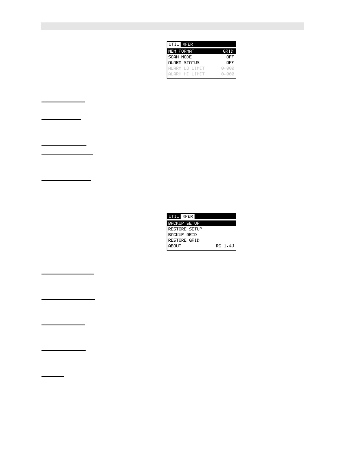
3.7 UTIL (utilities) – Menu
Mem Format: Allows the user to select between a general grid style format and
engine block format for data storage. Refer to page 60 for further info.
Scan Mode: This function enables a hi speed scan mode that increases the overall
sample rate from the standard 4 measurements a second to 32 measurements a
second. Refer to page 56 for further info.
Alarm Status: Toggles alarm mode on or off. Refer to page 57 for further info.
Alarm LO Limit: Gives the user the ability to set the LO limit parameter. If the
measurement falls below this value, a red light will illuminate and sound the internal
beeper. Refer to page 58 for further info.
Alarm HI Limit: Gives the user the ability to set the HI limit parameter. If the
measurement exceeds this value, a red light will illuminate and sound the internal
beeper. Refer to page 59 for further info.
3.8 XFER (transfer) – Menu
Backup Setups: Enables the user the ability to backup the setups currently stored
in the PR-8V to a PC via RS232 port. Refer the help section of the PR-8Vsonicview
software for a complete electronic manual.
Restore Setups: Enables the user the ability to restore the setups currently saved
on a PC to an PR-8V via RS232 port. Refer the help section of the PR-8Vsonicview
software for a complete electronic manual.
Backup Grid: Enables the user the ability to backup grids currently stored in the PR-
8V to a PC via RS232 port. Refer the help section of the PR-8Vsonicview software
for a complete electronic manual.
Restore Grid: Enables the user the ability to restore grids currently saved on a PC
to an PR-8V via RS232 port. Refer the help section of the PR-8Vsonicview software
for a complete electronic manual.
About: Provides the user with Dakota Ultrasonics contact information and the PR8V software version. Refer the help section of the PR-8Vsonicview software for a
complete electronic manual.
16
Page 21
PR-8V High Performance Thickness Gauge
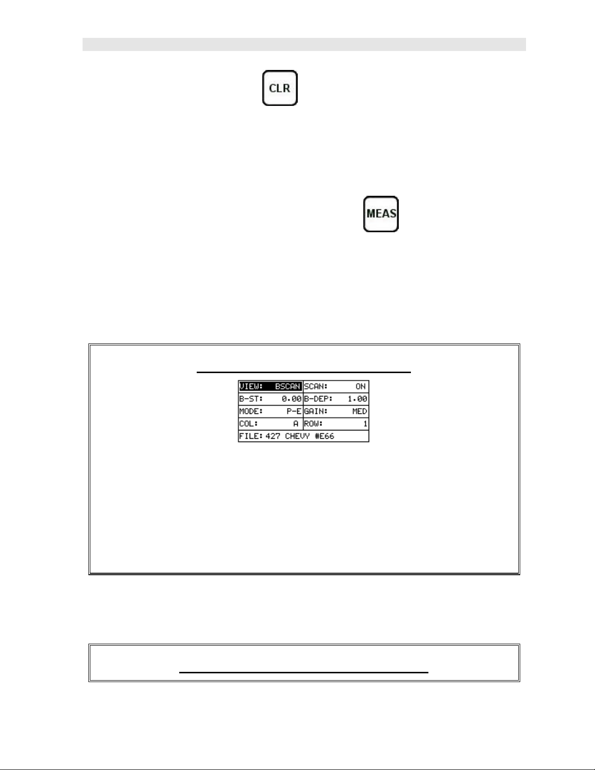
3.9 CLR (clear) Key
The primary functions of the CLR key, is to clear a measurement from a grid cell
location or set obstruct, and backspace in an Alpha Edit Box. If a user has already
saved a measurement and waveform to a cell location, use this key to clear the
measurement at any time.
3.10 MEAS (measurement mode) Key
The MEAS key puts the PR-8V into it’s primary mode of operation. In this mode, the
user has a complete view of the LCD, as well as control of the Hot Menu Functions.
These hot functions provide the user with the ability to make crucial adjustments to
the display, waveform settings, and grid storage locations without having to search
through the menu and sub menu items. It’s important to first get familiar with moving
around in the hot functions as follows:
Getting Around in the Hot Menus
1) Press the MEAS key at any time to return to the primarily measurement
mode.
2) Press the MEAS key multiple times to tab right through the menu fields, and
the ESC key multiple times to tab left through the menu fields, until the
desired hot function is highlighted.
Now that you’re familiar with activating and moving amongst the hot function fields,
let’s have a look at how to adjust or change the values of these fields:
Adjusting the Values of the Hot Menus
17
Page 22
Dakota Ultrasonics
1) Use the UP, DOWN, LEFT, and RIGHT arrow keys to increase and
decrease the values of the hot function fields.
2) Repeat step 1 until the desired value has been achieved.
Alternatively, the B-ST and B-DEP hot function fields can be changed using
the Digit Edit Box as follows:
1) Press the ENTER key to display the Digits Edit Box.
2) Press the UP and DOWN arrow keys to scroll the highlighted value.
3) Press the LEFT and RIGHT arrow keys to scroll the digit locations.
4) Repeat steps 2 & 3 until the delay, width, gain, or threshold number is
correctly displayed.
5) Press the OK key to set and return to the measure screen, or ESC to cancel
entering the B-ST or B-DEP values.
3.11 OK Key
The primary function of the OK key is confirmation of a change or selection. It also
toggles the view from B -SCAN to DIGITS in previously saved grid location.
3.12 ESC Key
The ESC key is used in the MENU, MEAS, and EDIT functions as a back or escape
function. It also toggles the view from B -SCAN to DIGITS in previously saved grid
location.
3.13 Arrow Keys
18
Page 23

PR-8V High Performance Thickness Gauge
The Arrow Keys are used to navigate through the menus, increase/decrease values,
and toggle specific function keys.
3.14 ENTER key
The ENTER key is used in the overall menu selection process, to activate list and
edit boxes, and save measurements to grid locations.
3.15 MULTI MODE Key
The MULTI MODE key toggles the measurement mode of the PR-8V, from pulse-
echo (flaw mode), to echo-echo (thru paint) mode. This is a quick automatic preset
mode that enables the user to change modes without having to manually adjust the
mode between pulse-echo and echo-echo. Both modes have been configured for
use with any transducer type selected.
3.16 ON/OFF Key
The ON/OFF key simply powers the unit either ON or OFF. Note: Unit will
automatically power off when idle for 5 minutes. All current settings are saved prior
to powering off.
3.17 Top & Bottom End Caps
19
Page 24

Dakota Ultrasonics
The top & bottom end panels are where all connections are made to the PR-8V. The
diagram above shows the layout and description of the connectors:
Transducer Connectors
Refer to Diagram: The transducer connectors, and battery cover/probe zero disk are
located on the PR-8V’s top end cap. The transducer connectors are of type Lemo
“00”. Note: There is no polarity associated with connecting the transducer to the PR-
8V.
Probe Zero Disk & Battery Cover
Refer to Diagram: The Battery cover is the large round disk shown in the diagram.
Note: This same disk is also used as a probe zero disk. Simply remove the cover
when replacing the batteries (3 AA cells). When performing a probe zero function,
simply place the transducer on disk making firm contact. Important: Be sure to
follow the polarity labels located on the back label of the PR-8V. Note:
Rechargeable batteries can be used, however they must be recharged outside of the
unit in a stand alone battery charger.
RS-232 Connector
Refer to Diagram: The RS-232 connector, located on the bottom end cap, is a 2 pin
female Lemo connector. It is designed to connect directly from the PR-8V to a
standard AT serial port on a PC. The cable supplied with the PR-8V is a Lemo to 9
pin serial cable. Note: This connector is also used to upgrade the PR-8V with th e
latest version of firmware.
20
Page 25

CHAPTER FOUR
PRINCIPALS OF ULTRASONIC MEASUREMENT
4.1 Time versus thickness relationship
Ultrasonic thickness measurements depend on measuring the length of time it takes
for sound to travel through the material being tested. The ratio of the thickness
versus the time is known as the sound velocity. In order to make accurate
measurements, a sound velocity must be determined and entered into the
instrument.
The accuracy of a thickness measurement therefore depends on having a consistent
sound velocity. Some materials are not as consistent as others and accuracy will be
marginal. For example, some cast materials are very granular and porous and as a
result have inconsistent sound velocities.
While there are many different ultrasonic techniques to measure thickness, which will
be discussed below, all of them rely on using the sound velocity to convert from time
to thickness.
4.2 Suitability of materials
Ultrasonic thickness measurements rely on passing a sound wave through the
material being measured. Not all materials are good at transmitting sound.
Ultrasonic thickness measurement is practical in a wide variety of materials including
metals, plastics, and glass. Materials that are difficult include some cast materials,
concrete, wood, fiberglass, and some rubber.
4.3 Range of measurement and accuracy
The overall measurement capabilities, based on the wide variety of materials, is
determined by the consistency of the material being measured
The range of thickness that can be measured ultrasonically depends on the material
as well as the technique being used and the type of transducer. Thickness
measurements can be made from a minimum of 0.010 inch to 9.999” in steel.
However, the maximum attainable thickness is much less for more attenuative
materials (materials that absorb sound).
Accuracy, is determined by how consistent the sound velocity is through the sound
path being measured and, is a function of the overall thickness of the material. For
example, the velocity in steel is typically within 0.5% while the velocity in cast iron
can vary by 4%.
4.4 Couplant
All ultrasonic applications require some medium to couple the sound from the
transducer to the test piece. Typically a high viscosity liquid is used as the medium.
The sound frequencies us ed in ultrasonic thickness measurement do not travel
21
Page 26

Dakota Ultrasonics
through air efficiently. By using a liquid couplant between the transducer and test
piece the amount of ultrasound entering the test piece is much greater.
4.5 Temperature
Temperature has an effect on sound velocity. The higher the temperature, the slower
sound travels in a material. High temperatures can also damage transducers and
present a problem for various liquid couplants.
Since the sound velocity varies with temperature it is important to calibrate at the
same temperature as the material being measured.
Normal temperature range
Most standard transducers will operate from 0°F to 180°F.
High temperature measurements
Special transducers and couplants are available for temperatures above 180°F up to
650°F with intermittent contact. It is necessary to cool the transducer, by submerging
the transducer in water between readings, when measuring high temperatures.
Modes and temperature errors
In addition to errors caused by velocity changing with temperature, some modes
(measurement techniques) are affected more than others. For example, dual
element mode has larger errors due to changes in temperature of the delay line.
However, multi-echo techniques help to minimize these errors.
4.6 Measurement Modes
In this section we will discuss the different measurements modes the PR-8V is
capable of operating in, the transducers required, and the reasons for using specific
modes:
Pulse-Echo Mode (Flaw & Pit detection)
Pulse-echo mode measures from the initial pulse (sometimes referred to as an
artificial zero) to the first echo (reflection). In this mode, the transducer is placed on a
reference disk, located on top of the PR-8V, and a key is pressed to establish a zero
point for the particular transducer.
In this mode errors result from surface coatings and temperature variations.
Since pulse-echo only requires one reflection, it is the most sensitive mode for
measuring weak reflections (flaws) typically found when measuring heavily corroded
metals.
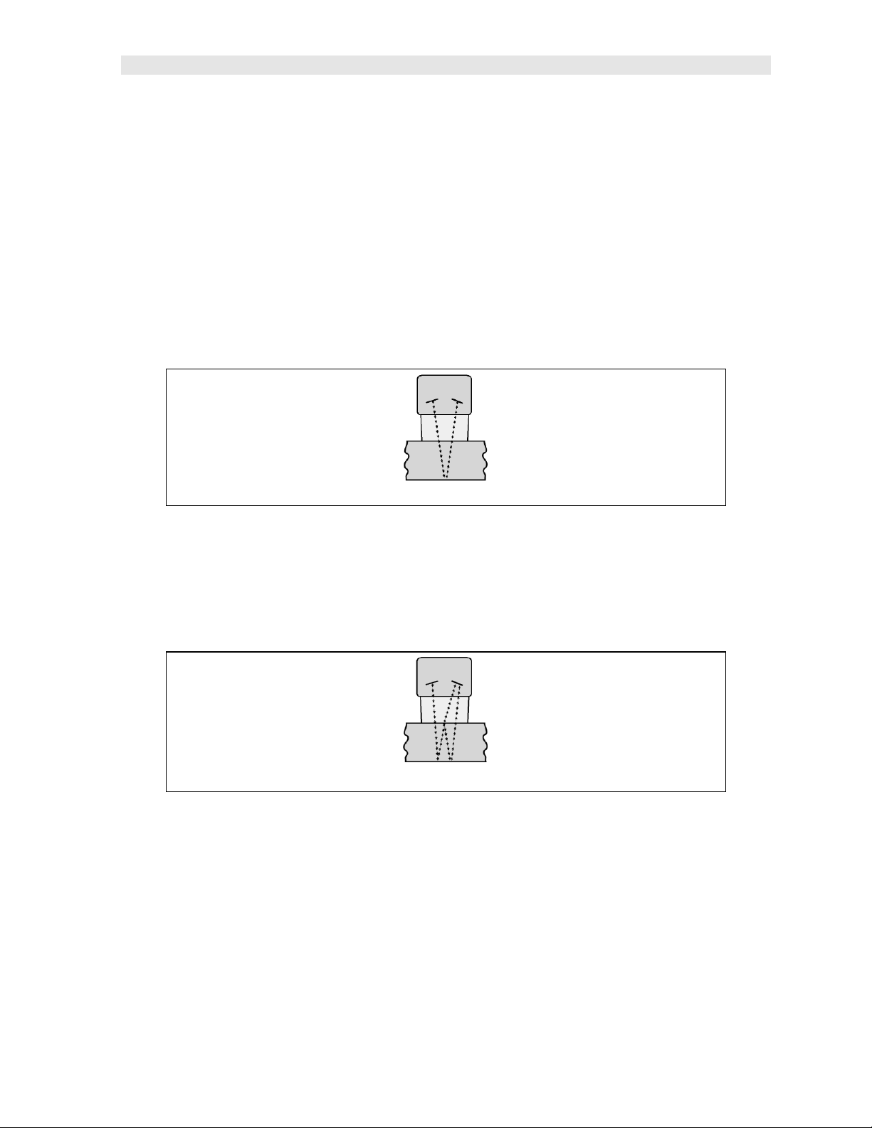
V-Path Correction
Dual element delay line transducers have two piezoelectric elements mounted at an
angle on one end of the delay line. One element is used for transmitting sound, while
the other element only receives sound. The two elements and their delay lines are
22
Page 27
PR-8V High Performance Thickness Gauge
packaged in a single housing but acoustically isolated from each other with a sound
barrier. This allows the transducer the ability to achieve very high sensitivity for
detecting small defects. Also, the surface of the test material does not have to be as
flat in order to obtain good measurements.
Dual element transducers are normally used in pulse-echo mode for finding defects,
and in echo-echo mode for through coating measurements.
Dual element delay line transducers are usable over a range of 0.025 inches t o 20
inches depending on the material, frequency, and diameter.
A limitation of dual element delay-line transducers is the V shaped sound path.
Because the sound travels from one element to another, the time versus thickness
relationship is non-linear. Therefore, a correction table in the instruments software is
used to compensate for this error.
Dual Element Transducer showing V-path of signal
Echo-Echo Mode
The echo-echo mode measures between two reflections. This technique is
commonly used to elimin ate errors from surface coatings and also to make
measurements in multiple layered materials. The disadvantage is that two echoes
are needed which requires a much stronger echo (reflection).
Dual Element Transducer in Echo to Echo mode
Searching for small defects
Dual element delay line transducers are especially useful in searching for small
defects. In the pulse-echo mode with high amplifier gain, very small defects can be
measured. This is very useful during cylinder walls inspections and when porting
heads. The dual element style transducer will find porosity pockets and any potential
defects in the cylinders and head ports prior to boring or porting.
23
Page 28

Dakota Ultrasonics
4.7 Glossary of terms
Repetition Rate & Display Update
The repetition rate is how often the PR-8V generates a burst of ultrasound.
The PR-8V has a fixed repetition rate of 1 kHz, or 1000 times per second. The PR-
8V updates the display 4 times per second in regular measurement mode and 32
times a second in hi speed scan mode. Therefore, the scan mode is most suitable
for fast scans of a test piece at a lower resolution.
24
Page 29

CHAPTER FIVE
SELECTING THE MEASUREMENT MODE
5.1 The setup library
The PR-8V contains 64 user configurable preset locations to store custom setups for
easy recall. These setups can be optimized for the user’s specific application needs
and can also be stored on a PC and transferred bi-directionally using Dakota’s PC
interface software included with the instrument.
The setups supplied with the instrument cover some of the more typical applications
commonly used with this type of instrument. These setups can be recalled, modified,
and overwritten to one of 64 setup locations. Therefore, these factory setups can
also be considered a good starting point to be modified for custom applications. The
PC software includes a default setup file that can be uploaded to the gauge at any
time to restore factory settings. However, it is recommended that the user consider
saving modified setups to an empty location rather than overwriting the factory setups
in the PR-8V. Once again, these factory settings are excellent starting points for
custom setups.
5.2 Which mode & transducer do I use for my application?
High penetration plastics and castings
The most common mode for these types of applications is pulse-echo. Dakot a
manufactures specific transducers for the racing industry. The PR-8V has been
optimized for cast materials. Cast iron applications require a 5MHz frequency, and
cast aluminum will require a 10MHz frequency. However, plastics will require lower
frequencies depending on the thickness and make-up of the material. Larger
diameters offer greater penetration power because of the crystal size, for difficult to
measure materials.
Corrosion & Pit Detection in steel and cast materials
Use pulse-echo mode whenever attempting to locate pits and flaws. Typically a
5MHz transducer, or higher, will be used for these types of applications. Use low
frequencies for greater penetration and use higher frequencies for better resolution.
Thru Paint & Coatings
Often times users will be faced with applications where the material will be coated
with paint or some other type of epoxy material. Since the velocity of the coating is
approximately 2.5 times slower than that of steel, pulse-echo mode will induce error if
the coat ing or paint is not completely removed. By using echo-echo mode, the user
is able to successfully measure through both, the coating and steel, and completely
eliminate the thickness of the paint or coating. Therefore, the steel can be measured
without having to remove the coating prior to measuring. Users will often use pulse-
25
Page 30

Dakota Ultrasonics
echo mode and echo-echo mode in conjunction when performing inspections on
coated materials.
Thru coating measurements require special high damped transducers. The most
common tran sducers are the 3.5, 5, and 7.5MHz hi damped transducers. These
transducers are suitable for use in both pulse-echo and echo-echo modes. This
conveniently enables the user to accurately measure overall material thickness using
the thru Coating mode, and then conveniently switch to pit detection mode without
changing transducers. The ¼” 5MHz Hi damped transducer is best suited for the
sanctioning bodies for thru coating measurements on chassis tubing.
Thin materials
Use pulse echo mode and a high frequency transducer for these types of
applications. The most common transducers are the 7.5MHz and 10MHz models
with extra resolution. The higher frequencies provide greater resolution and a lower
minimum thickness rating overall.
High temperature
Use and select a special 2.25MHz and 5 MHz High temperature transducer for these
types of applications. Both pulse-echo and echo-echo modes will also work for these
applications. However, echo-echo mode will eliminate error caused by temperature
variations in the delay line of the transducer.
Noisy Material
Materials such as titanium, stainless steel, and aluminum may have inherent surface
noise issues. This is a signal that appears at the surface of the material when using
a dual element delay line probe. Select a h igher frequency transducer to reduce this
noise – 7.5MHz and higher for better resolution.
Restricted access
In order to measure materials with lots of curvature or restricted access, use and
select higher frequencies with smaller diameters. The smallest diameter uses 3/16”
crystals with a contact area of .250”.
26
Page 31

PR-8V High Performance Thickness Gauge
STEEL THRU PNT EXT
PAINT (RACING)
½" 5MHZ
5.3 Factory Setup Chart
Num Name Comment 1 Gn/AGC Velocity
1 STEEL BASIC ¼” 5MHZ MED 0.2330 in/uSec
2 STEEL THRU PNT STD ¼ 5MHZ HD AGC 0.2330 in/uSec
3
4 THRU5 CAST IRON (BASIC)
6 CAST ALUMINUM (BASIC) ¼ 10MHZ MED 0.2510 in/uSec
½ 3MHZ HD AGC 0.2330 in/uSec
¼” 5MHZ AGC 0.2330 in/uSec
MED 0.1800 in/uSec
27
Page 32

CHAPTER SIX
MAKING MEASUREMENTS
The steps involved in making measurements are detailed in this section. The
following sections outline how to setup and prepare your PR-8V for field use.
In pulse-echo modes, the probe zero must be measured on the reference disk
(battery disk) attached to the top of the instrument. This compensates for variations
in the transducer. In all modes the sound velocity must be determined. The sound
velocity is used to convert the transit time to a physical length. The sound velocity
can be selected from a material chart in the manual, selected from a material list in
the PR-8V, or for greater precision, determined from a sample of the test material
that has been mechanically measured. To enter the velocity from a table, look up the
material on th e chart in the appendix of this manual and refer to the section below on
Calibration to a Known Velocity. To determine the velocity of a single sample, refer
to the Material Calibration section on page 36.
When measuring curved materials, it is more accurate to calibrate from two test
points, one at the minimum limit of the target thickness and one at the maximum limit.
In this case the reference disk mounted to the PR-8V is not used. This is called twopoint calibration and is described on page 37.
6.1 Selecting The Transducer Type
The first step in using the PR-8V is to select the transducer type from the transducer
list located in the tabbed menu items by frequency and diameter. By selecting th e
transducer type from a predefined list, the PR-8V can recall specific properties about
the transducer. Note: Once the transducer has been selected, the PR-8V will store
and recall this transducer type every time the PR-8V is powered on/off. The type will
only change if the user physically selects another type from the list, or selects a
previously saved setup. Therefore, if you have previously gone through this section
and selected the transducer you are using, proceed to the next section. Use the
following steps to select your transducer type. Note: Be sure the transducer type
selected is the same as the transducer plugged into the PR-8V. Failure to do this
will result in erroneous measurements:
28
Page 33

PR-8V High Performance Thickness Gauge
Selecting the Transducer Type
1) Press the MENU key once to activate the menu items tab. Press the MENU
key multiple times to tab right and the ESC key multiple times to tab left until
the PROBE menu is highlighted and displaying the submenu items.
2) Use the UP and DOWN arrow keys to scroll through the sub menu items
until TYPE is highlighted.
3) Press the ENTER key to display the list of transducer types.
4) Press the UP and DOWN arrow keys to scroll through the transducer list
until the appropriate type is highlighted.
5) Press the ENTER key to display the confirmation screen.
6) Press the OK key to select the transducer and return to the menu screen, or
ESC to cancel the material selection.
Now that the proper transducer has been selected and connected to the PR-8V, the
measurement mode must be chosen according to th e type of application. Following
the recommendations in the prior chapter, there are three different ways to select the
measurement mode as follows:
29
Page 34

Dakota Ultrasonics
Selected from a Setup
Important Note: Stored setups will save all the parameters of the PR-8V.
Therefore, if a transducer was selected in the previous section and a setup is
now being recalled, the transducer saved in the setup will overwrite the
transducer previously selected. Be sure the transducer saved with the setup is
the same as the transducer currently being used. Alternatively, you can select
a transducer again after recalling a setup. This will override the transducer
saved with the setup.
1) Press the MENU key once to activate the menu items tab. Press the MENU
key multiple times to tab right and the ESC key multiple times to tab left until
the SETUP menu is highlighted and displaying the submenu items.
2) Use the UP and DOWN arrow keys to scroll through the sub menu items
until OPEN is highlighted.
3) Press the ENTER key to display the list of stored setups.
4) Press the UP and DOWN arrow keys to scroll through the list of setups until
the appropriate setup is highlighted.
5) Press the ENTER key to display the confirmation screen.
30
Page 35

PR-8V High Performance Thickness Gauge
6) Press the OK key to select the setup and return to the menu screen, or ESC
to cancel the selection process.
7) Press the MEAS key to return to the measurement screen.
Alternatively, the measurement mode can be simply selected from the Hot Menu
Items or selected from a sub menu feature as follows:
Hot Menu Selection
1) Press the MEAS key once to activate measure menu items. Press the
MEAS key multiple times to move right and the ESC key multiple times to
move left, until the MODE cell is highlighted.
2) Use the UP, DOWN, LEFT, or RIGHT arrow keys to scroll the modes P-E
(pulse-echo flaws and pits) and E-E (echo-echo thru paint) until the target
mode is selected.
Finally, the measurement mode can be selected from the menu items as follows:
31
Page 36

Dakota Ultrasonics
Selected Using The Tabbed Submenu Items
1) Press the MENU key once to activate the menu items tab. Press the MENU
key multiple times to tab right and the ESC key multiple times to tab left until
the PROBE menu is highlighted and displaying the submenu items.
2) Use the UP and DOWN arrow keys to scroll through the sub menu items
until MEASURE MODE is highlighted.
3) Use the LEFT and RIGHT arrow keys to scroll the mode options. Once the
mode is displayed, press the MEAS key to return to the measurement mode
screen.
6.2 Probe zero
As noted in chapter 3, the probe zero function is a very important and necessary
function that must done prior to calibration. It should also be done on a regular basis.
If the PR-8V is not zeroed correctly, all of the measurements taken, may be in error
by some fixed value. In order to perform a probe zero, the PR-8V must be in pulse-
echo mode. If echo-echo mode was previously selected in the last section, skip this
section and continue on to the next. Note: If you intend to switch between
measurement modes simultaneously, temporarily select the pulse-echo mode using
the hot menu option, perform the probe zero function, and switch back to echo-echo
measurement mode after zeroing. The following steps outline the procedure for
performing a probe zero:
32
Page 37

PR-8V High Performance Thickness Gauge
Performing a Probe Zero
1) Clean the surface of the Probe Zero Disk, located on top of the PR-8V
(battery cover).
2) Apply a drop of couplant to the end of the transducer, or probe disk, and
hold the transducer in steady contact with the reference disk.
3) Press the MENU key once to activate the menu items tab. Press the MENU
key multiple times to tab right and the ESC key multiple times to tab left until
the PROBE menu is highlighted and displaying the submenu items.
4) Use the UP and DOWN arrow keys to scroll through the sub menu items
until ZERO TRANSDUCER is highlighted.
5) Press the ENTER key to display the confirmation screen.
6) Press the OK key to zero the transducer and return to the menu screen, or
ESC to cancel the zeroing process.
7) Remove the transducer from the probe zero disk.
8) Press the MEAS key to return to the measurement screen.
6.3 Material Calibration
In order for the PR-8V to make accurate measurements, it must be set to the correct
sound velocity of the material being measured. Different types of materials have
different inherent sound velocities. For example, the velocity of sound through steel
is about 0.233 inches per microsecond, versus that of aluminum, which is about
0.248 inches per microsecond. If the gauge is not set to the correct sound velocity,
33
Page 38

Dakota Ultrasonics
all of the measurements the gauge makes will be erroneous by some fixed
percentage.
The One Point calibration is the simplest and most commonly used calibration
method - optimizing linearity over large ranges. The Two Point calibration allows for
greater accuracy over small ranges by calculating the probe zero and velocity. The
PR-8V provides four simple methods for setting the sound-velocity outlined below:
Calibration to a known velocity
1) Press the MENU key once to activate the menu items tab. Press the MENU
key multiple times to tab right, and the ESC key multiple times to tab left,
until the CAL menu is highlighted and displaying the submenu items.
2) Use the UP and DOWN arrow keys to scroll through the sub menu items
until VELOCITY is highlighted.
3) Press the ENTER key to display the Digits Edit Box.
4) Press the UP and DOWN arrow keys to scroll the highlighted value.
5) Press the LEFT and RIGHT arrow keys to scroll the digit locations.
6) Repeat steps 4 & 5 until the velocity number is correctly displayed.
7) Press the OK key to set the velocity and return to the menu screen, or ESC
to cancel entering the velocity.
34
Page 39

PR-8V High Performance Thickness Gauge
8) Finally, press the MEAS key to return to the measurement screen and begin
taking readings.
35
Page 40

Dakota Ultrasonics
One Point Calibration
Note: Be sure that a probe zero has been done prior to performing this
calibration procedure.
1) Physically measure a location on the sample to be measured using a set of
calipers or a digital micrometer. Note: It’s always best to calibrate on the
thickest location on the sample, rather than on the thinnest location, as the
percentage error is much less with respect to the PR-8V’s resolution of +/-
.001” (0.01mm).
2) Apply a drop of couplant on the transducer. Place the transducer in steady
contact on the known thickness location. Be sure that the reading is stable
and the repeatability indicator, located in the top left corner of the display, is
fully lit and stable. Press the MENU key once to activate the menu items tab.
Press the MENU key multiple times to tab right and the ESC key multiple
times to tab left until the CAL menu is highlighted and displaying the
submenu items.
3) Use the UP and DOWN arrow keys to scroll through the sub menu items
until ONE POINT is highlighted.
36
Page 41

PR-8V High Performance Thickness Gauge
4) Press the ENTER key to display the Digits Edit Box.
5) Press the UP and DOWN arrow keys to scroll the highlighted value.
6) Press the LEFT and RIGHT arrow keys to scroll the digit locations.
7) Repeat steps 5 & 6 until the known thickness value is correctly displayed.
8) Press the OK key to calculate the velocity and return to the menu screen, or
ESC to cancel entering the velocity.
9) Finally, press the MEAS key to return to the measurement screen and begin
taking readings.
Note: CHECK YOUR CALIBRATION! Place the transducer back on the
calibration point. The thickness reading should now match the known
thickness. If the thickness is not correct, repeat the steps above.
Two Point Calibration
Note: Be sure that a probe zero has been done prior to performing this
calibration procedure.
37
Page 42

Dakota Ultrasonics
1) Using a set of calipers, physically measure two known thickness locations
on the sample of material. Note: The two locations should represent the
desired thickness range being measured. If the range is from .250” - 1.000”,
then the two known locations should represent this range, or be slightly
outside or inside of this range. A typical example would be to find two
locations at .236” and the other at 1.047”. These thickness points will satisfy
the required thickness range noted above.
2) Apply a drop of couplant on the transducer. Place the transducer in steady
contact on thickest known location first. Be sure that the reading is stable
and the repeatability indicator, located in the top left corner of the display, is
fully lit and stable. Press the MENU key once to activate the menu items tab.
Press the MENU key multiple times to tab right, and the ESC key multiple
times to tab left, until the CAL menu is highlighted and displaying the
submenu items.
3) Use the UP and DOWN arrow keys to scroll through the sub menu items
until ONE POINT is highlighted.
4) Press the ENTER key to display the Digits Edit Box.
5) Press the UP and DOWN arrow keys to scroll the highlighted value.
6) Press the LEFT and RIGHT arrow keys to scroll the digit locations.
7) Repeat steps 5 & 6 until the known thickness value is correctly displayed.
8) Press the OK key to calculate the velocity for the ONE POINT calibration
and return to the CAL menu screen, or press ESC to cancel entering the
velocity.
9) Apply a drop of couplant on the transducer and place the transducer in
steady contact with the sample or actual test material on the thinnest, or
38
Page 43

PR-8V High Performance Thickness Gauge
second known thickness location. Be sure that the reading is stable and the
repeatability indicator, located in the top left corner of the display, is fully lit
and stable.
10) Use the UP and DOWN arrow keys to highlight the TWO POINT calibration
submenu item.
11) Press the ENTER key to display the Digits Edit Box.
12) Press the UP and DOWN arrow keys to scroll the highlighted value.
13) Press the LEFT and RIGHT arrow keys to scroll the digit locations.
14) Repeat steps 12 & 13 until the known thickness value is correctly displayed.
15) Press the OK key to calculate the velocity for the TWO POINT calibration
and return to the CAL menu screen, or press ESC to cancel entering the
velocity.
16) Finally, press the MEAS key to return to the measurement screen and
begin taking readings.
Note: CHECK YOUR CALIBRATION! Place the transducer back on both
calibration points. The thickness readings should now match the known
thickness locations. If they are not correct, repeat the steps above.
39
Page 44

Dakota Ultrasonics
Built in Material Selection
1) Press the MENU key once to activate the menu items tab. Press the MENU
key multiple times to tab right, and the ESC key multiple times to tab left,
until the CAL menu is highlighted and displaying the submenu items.
2) Use the UP and DOWN arrow keys to scroll through the sub menu items
until MATERIAL is highlighted.
3) Press the ENTER key to display the list of Material Types.
4) Press the UP and DOWN arrow keys to scroll through the material list until
the appropriate material is highlighted.
5) Press the ENTER key to display the confirmation screen.
6) Press the OK key to select the material and return to the menu screen, or
press ESC to cancel the material selection.
7) Finally, press the MEAS key to return to the measurement screen and begin
taking readings.
40
Page 45

CHAPTER SEVEN
USING THE DIGITS & B-SCAN DISPLAYS
A key feature of the PR-8V is the ability to toggle between two different display
options, Digits and B-Scan. The Digits view provides the user with a large digital
readout of the thickness. The Digits view also includes a scan bar features that uses
a bar graph to indicate thickness. The Scan bar can be very handy while scanning a
cylinder wall by graphically displaying deflections from porosity or internal flaws,
rather than having to constantly watch for changes in the digital readout. Just
another visual tool to alarm the user when something out of the ordinary is detected.
The B-Scan display is also very useful when scanning surfaces and viewing the cross
section of the test material. It provides a convenient way of profiling the blind
surfaces during a scan. The B-Scan display is also equipped with a scan bar
representing the overall thickness. Once again, the scan bar gives the user a visual
indication when a flaw or defect passed over during the scan process. The scan bar
will deflect off of the defect and return back to the overall thickness. Visually, this is
much easier to notice than watching for changes in the digital value displayed.
Note: The following chapter outlines some of the fine adjustment features of the PR-
8V. The PR-8V has two different display options (Large Digits and B-Scan). We’ll
take a better look at these options in this chapter. Note: In order to recall and use
the new adjustments made to the PR-8V at a later time, the user must save the
modified settings in one of th e setup locations prior to powering off the unit. Refer
page 79 for more information on setups.
7.1 Selecting a Display Option
The following procedure outlines how to select or toggle display options:
Changing Display Options
41
Page 46

Dakota Ultrasonics
1) Press the MENU key once to activate the menu items tab. Press the MENU
key multiple times to tab right, and the ESC key multiple times to tab left,
until the DISP menu is highlighted and displaying the submenu items.
2) Use the UP and DOWN arrow keys to scroll through the sub menu items
until VIEW is highlighted.
3) Use the LEFT and RIGHT arrow keys to scroll the view options. Once the
appropriate view is displayed, press the MEAS key to return to the
measurement screen.
7.2 Display Views
DIGITS VIEW
DIGITS
The Digits view is a basic digital thickness gauge look and feel. The larger digits
make it much easier for the operator to monitor the thickness readings. The Scan
Bar has also been added to the Digits view to provide the user with yet another visual
tool for easily monitoring changes in thickness readings due to internal flaws or
defects.
42
Page 47

PR-8V High Performance Thickness Gauge
The following is a list of the viewable features on the display:
A) Stability of Reading Indicator – Indicates the stability of the return echo on a
scale of 1 to 6 – the solid bars displayed in the figure above indicate a repeatable
signal. If the PR-8V is displaying a reading from memory, the repeatability
indicator will be replaced by the text “MEM”.
B) Battery life indicator – Fully charged batteries will appear filled in solid. Note:
The diagram shows the batteries at approximately 50%.
C) Thickness reading – Digital readout of thickness (inches or millimeters).
D) Large Digits – Large readout of thickness (inches or millimeters).
E) Units Label – Display’s the current unit of measurement (inches or millimeters).
F) Measurement Labels – The measurement labels are calculated and displayed
based on where the left side of the display has been set (Delay), and the overall
viewable area (Width) of the display. Note: The gray hash marks break the
display up into 5 segments, or quadrants. The measurement labels correspond to
the measurement at each hash mark.
G) Scan Bar – The scan bar corresponds directly with thickness represented by the
horizontal labels on the on the display. As you can see from the diagram above,
the filled horizontal bar is displayed at .500”. This display can be very useful
when scanning materials in either B-Scan or Digits display views. It is much
easier to watch and notice deflections for flaws and pits usin g the scan bar, rather
than trying to notice changes in the digital value. If the user is scanning a pipe,
for instance, and passes over a pit during the process, the scan bar will quickly
deflect and alarm the user to go back and search for the defect.
H) Hot Menus - Each of the fields located under the display are called the Hot Menu
Fields. These fields allow quick control of some of the fine adjustments needed
to control the display settings, measurement modes, and grid memory control.
All of these fields can be adjusted without having to activate the tabbed menu
items and searching through a variety of menus to make adjustments.
43
Page 48

Dakota Ultrasonics
B-Scan
B-Scan View
The B-Scan displays a time based cross section view of test material. This view is
commonly used to display the contour of the blind, or underside, surface of a pipe or
tank application. It is very similar to a fish finder. If a flaw or pit is located during a
scan, the B-Scan will draw the pit on the screen. The solid black rectangle in the
diagram at location E represents the cross section, or side view of the material. You
will notice that the overall thickness of the material is .500”, and the display range is
0.00” to 1.00” respectively. The B-Scan view draws at a rate of 15 seconds per
screen from right to left. Also notice at location J, the pits and corroded bottom
surface of the material.
It’s important to note that the measurement range on the display be set wide enough,
so that the maximum thickness of the material can be viewed on the display. Using
the diagram above, if the material thickness was actually 1.75”, the underside of the
material would not be viewable according to the current range at 0.00” – 1.00”. All
the user would see is a black screen from 0.00” – 1.00” with no view of the bottom
contour at 1.75”.
The following is a list of the viewable features on the display:
A) Stability of Reading Indicator – Indicates the stability of the echo signal on a
scale of 1 to 6 – the solid bars displayed in the figure above indicate a repeatable
signal. If the PR-8V is displaying a reading from memory, the repeatability
indicator will be replaced by the text “MEM”.
B) Battery life indicator – Fully charged batteries will appear filled in solid. Note:
The diagram shows the batteries at approxim ately 50%.
C) Thickness reading – Digital readout of thickness (inches or millimeters).
44
Page 49

PR-8V High Performance Thickness Gauge
D) B-Scan Display Area – This is the area representing where the B-Scan will be
drawn. Notice the range of the area in the diagram at 0.00” – 1.0” respectively.
E) Displayed B-Scan – Graphical presentation of the cross section, or side view of
the test material. The top, or accessible side of the material represented as 0.00”,
and the bottom, or blind surface at .500”. You will notice the contour in the BScan, indicating a very corroded bottom surface. The B-Scan is displayed from
right to left at a rate of 15 screens per second.
F) Measurement Labels – The measurement labels are calculated and displayed
based on where the left side of the display has been set (Delay), and the overall
viewable area (Width) of the display. Note: The gray hash marks break the
display up into 5 segments, or quadrants. The measurement labels correspond to
the measurement at each hash mark.
G) Units Label - Display’s the current unit of measurement (inches or millimeters).
H) Hot Menus - Each of the fields located under the B-Scan display are called the
Hot Menu Fields. These fields allow quick control of some of the fine
adjustments needed to control the display settings, measurement modes, and grid
memory control. All of these fields can be adjusted without having to activate the
tabbed menu items and searching through a variety of menus to make
adjustments.
I) Scan Bar – The scan bar corresponds directly with thickness represented by the
horizontal labels on the on the display. As you can see from the diagram above,
the filled horizontal bar is displayed at .500”. This display can be very useful
when scanning materials in either B-Scan or Digits display views. It is much
easier to watch and notice deflections for flaws and pits using the scan bar, rather
than trying to notice changes in digital values. If the user is scanning a pipe, for
instance, and passes over a pit in the process, the scan bar will quickly deflect
and alarm the user to go back and search for the defect.
J) Contour (blind surface) – A view of the B-Scan displaying the blind side surface
contour of the material.
7.3 Adjusting the B-Scan Start (B-ST) & Depth (B-DEP)
In order to use the B-Scan and Scan Bar features of the PR-8V effectively, the
starting depth and overall depth must be setup correctly. This can be adjusted using
the B-ST (start) and the B-DEP (depth) features of the PR-8V. The B-ST refers to
the starting depth or thickness value displayed. Example: If you want your B-Scan
or Scan Bar to start at a zero thickness value, then B-ST must be set to 0.000”. If
you want the B-Scan and Scan Bar to start displaying at .125”, then B-ST must be
set to .125”. B-DEP represents overall viewable thickness range being tested.
Example: If your measuring cylinder walls with a total thickness of .300”, and your B-
ST has been set to 0.000”, you might consider setting your B-DEP value to
something like 0.400” to cover the entire thickness range being tested. You might
also consider B-DEP as a zoom feature for both the B-Scan and Scan Bar. Why?
Because the larger the overall thickness range view (B-DEP), the smaller the
noticeable shifts in the Scan Bar and B-Scan presentation. Therefore, it’s best to set
45
Page 50

Dakota Ultrasonics
the B-ST and B-DEP to reasonable values that zoom in and optimize your graphic
representations.
Overall range (B-DEP)
Once again, just to reiterate, B-DEP is the overall viewable thickness range being
tested. This should be set to a valuable slightly larger then the expected maximum
range being measured. The procedures to adjust the overall thickness range viewed
(B-DEP) are outlined below:
Adjusting the Depth (B-DEP) using the Hot Menus
1) Press the MEAS key once to activate measure menu items. Press the
MEAS key multiple times to move right and the ESC key multiple times to
move left, until the B-DEP cell is highlighted.
2) Press the UP, DOWN, LEFT, and RIGHT arrow keys to scroll the highlighted
value.
3) Alternatively, press the ENTER key to display the Digits Edit Box.
4) Press the UP and DOWN arrow keys to scroll the highlighted value.
5) Press the LEFT and RIGHT arrow keys to scroll the digit locations.
6) Repeat steps 4 & 5 until the B-DEP value is correctly displayed.
46
Page 51

PR-8V High Performance Thickness Gauge
7) Press the OK key to return to the measurement screen, or ESC to cancel
entering the B-DEP.
The user can also access and adjust the B-DEP range from the tabbed menus.
However, this method is a more tedious than making the adjustments using the Hot
Menus. The procedure using the tabbed menus is outlined below:
47
Page 52

Dakota Ultrasonics
Adjusting the Overall Depth (B-DEP) using the Tabbed Menus
1) Press the MENU key once to activate the menu items tab. Press the MENU
key multiple times to tab right, and the ESC key multiple times to tab left,
until the DISP menu is highlighted and displaying the submenu items.
2) Use the UP and DOWN arrow keys to scroll through the sub menu items
until BSCAN DEPTH is highlighted.
3) Press the LEFT and RIGHT arrow keys to scroll the value. When the
correct width is being displayed, proceed to step 8.
4) Alternatively, press the ENTER key to display the Digits Edit Box.
5) Press the UP and DOWN arrow keys to scroll the highlighted value.
6) Press the LEFT and RIGHT arrow keys to scroll the digit locations.
7) Repeat steps 5 & 6 until the Bscan Depth value is correctly displayed.
8) Press the OK key to set the Bscan Depth and return to the menu screen, or
ESC to cancel entering the Bscan Depth.
48
Page 53

PR-8V High Performance Thickness Gauge
9) Finally, press the MEAS key to return to the measurement screen and begin
taking readings.
Starting depth (B-ST)
The starting B-ST, or starting depth, is the starting thickness value. Often times this
value will simply be set to zero in order to start measuring at 0.000”. The only time
this value will be set to something other than zero, is if the user needs to zoom in
even closer. When will this be the case? If the user is testing a material that’s 1 inch
in thickness and knows that the potential corrosion is only on the back surface of the
material and not possibly deeper than .200”. In this case, the user may wish to set
the B-ST at .700” to zoom in closer to the actual area being tested. In turn, the BDEP might be set at 1.100” in order to cover the entire range respectively. This will
offer the user better resolution for both the B-Scan and Scan Bar graphical
presentations.
Note: Once the range is set, it will remain the same for all the views respectively.
The procedures to adjust the starting depth (B-ST) are outlined below:
Adjusting the Starting Depth (B-ST) using the Hot Menus
1) Press the MEAS key once to activate measure menu items. Press the
MEAS key multiple times to move right and the ESC key multiple times to
move left, until the B-ST cell is highlighted.
49
Page 54

Dakota Ultrasonics
2) Press the UP, DOWN, LEFT, and RIGHT arrow keys to scroll the highlighted
value.
3) Alternatively, press the ENTER key to display the Digits Edit Box.
4) Press the UP and DOWN arrow keys to scroll the highlighted value.
5) Press the LEFT and RIGHT arrow keys to scroll the digit locations.
6) Repeat steps 4 & 5 until the B-ST value is correctly displayed.
7) Press the OK key to return to the measurement screen, or ESC to cancel
entering the B-ST.
The user can also access and adjust the B-ST from the tabbed menus. However,
this method is more tedious than making the adjustments using the Hot Menus. The
procedure using the tabbed menus is outlined below:
Adjusting the Starting Depth (B-ST) using the Tabbed Menus
1) Press the MENU key once to activate the menu items tab. Press the MENU
key multiple times to tab right, and the ESC key multiple times to tab left,
until the DISP menu is highlighted and displaying the submenu items.
50
Page 55

PR-8V High Performance Thickness Gauge
2) Use the UP and DOWN arrow keys to scroll through the sub menu items
until BSCAN START is highlighted.
3) Press the LEFT and RIGHT arrow keys to scroll the value. When the
correct Bscan Start is being displayed, proceed to step 8.
4) Alternatively, press the ENTER key to display the Digits Edit Box.
5) Press the UP and DOWN arrow keys to scroll the highlighted value.
6) Press the LEFT and RIGHT arrow keys to scroll the digit locations.
7) Repeat steps 5 & 6 until the Bscan Start number is correctly displayed.
8) Press the OK key to set the Bscan Start and return to the menu screen, or
ESC to cancel entering the Bscan Start.
9) Finally, press the MEAS key to return to the measurement screen and begin
taking readings.
7.4 Gain
The gain, or amplification of the return echoes, can be adjusted in the PR-8V to
accommodate a variety of applications. The setting of the gain is crucial in order to
obtain valid readings during the measurement process. Too much gain may result in
erroneous measurements, by detecting on noise rather than the actual material back
wall itself. Not enough gain may result in intermittent detection. It may also result in
lack of detection on internal flaws, pits, or porosity. The gain can easily be compared
to the volume control of a home stereo system. If you turn it up too much, you can’t
hear the music clearly. If it’s turned down too much, you can’t hear it at all.
The PR-8V has three gain settings (low, med, high) . Note: The PR-8V has been
optimized for the MED gain setting for all common performance racing applications.
It should be operated in this mode as standard. However, some applications may
require the low or high gain setting. When? The low set ting may be necessary for
certain cast aluminum materials, or very extremel y granular cast iron materials. How
do I know when to lower the gain? If the reading becomes sporadic and won’t settle
down or resolve on a thickness value, the user can assume that the material is either
51
Page 56

Dakota Ultrasonics
very noisy aluminum, or granular cast iron. This would be a good time to change the
PR-8V to low gain setting and see if the reading settles down and become stable.
How do I know when to increase the gain? Often times the user will be trying to
measure a material that is hard to penetrate or pass sound through. This may be
due to the material type, or overall thickness of the material. When a material is hard
to pass sound through because of the thickness or general make-up, it would be a
good time to consider switching the PR-8V into a high gain setting. In any case, the
selectable gain settings offer the user some additional options to resolve application
issues.
Note: When the echo-echo thru-paint measurement mode is selected, the gain
manual gain feature is disabled and grayed out in the menu items. In this mode, the
PR-8V switches to an automatic gain mode (AGC), that optimizes the gain setting
automatically in the hardware of the PR-8V.
The procedures to adjust the Gain are outlined below:
Adjusting the Gain using the Hot Menus
1) Press the MEAS key once to activate measure menu items. Press the
MEAS key multiple times to move right, and the ESC key multiple times to
move left until the GAIN cell is highlighted.
2) Press the UP, DOWN, LEFT, and RIGHT arrow keys to scroll the highlighted
value.
3) Alternatively, press the ENTER key to display the Digits Edit Box.
4) Press the UP and DOWN arrow keys to scroll the highlighted value.
5) Press the LEFT and RIGHT arrow keys to scroll the digit locations.
6) Repeat steps 4 & 5 until the GAIN value is correctly displayed.
52
Page 57

PR-8V High Performance Thickness Gauge
7) Press the OK key to return to the measurement screen, or ESC to cancel
entering the GAIN.
The user can also access and adjust the gain from the tabbed menus. However, this
method is more tedious than making the adjustments using the Hot Menus. The
procedure using the tabbed menus is outlined below:
Adjusting the Gain using the Tabbed Menus
1) Press the MENU key once to activate the menu items tab. Press the
MENU key multiple times to tab right, and the ESC key multiple times to tab
left, until the PROBE menu is highlighted and displaying the submenu items.
2) Use the UP and DOWN arrow keys to scroll through the sub menu items
until GAIN is highlighted.
3) Press the LEFT and RIGHT arrow keys to scroll the value. When the
correct Gain is being displayed, proceed to step 8.
4) Alternatively, press the ENTER key to display the Digits Edit Box.
5) Press the UP and DOWN arrow keys to scroll the highlighted value.
6) Press the LEFT and RIGHT arrow keys to scroll the digit locations.
7) Repeat steps 5 & 6 until the Gain value is correctly displayed.
8) Press the OK key to set the Gain and return to the menu screen, or ESC to
cancel entering the Gain.
53
Page 58

Dakota Ultrasonics
9) Finally, press the MEAS key to return to the measurement screen and
begin taking readings.
54
Page 59

CHAPTER EIGHT
THRU PAINT MEASUREMENT TECHNIQUE
8.1 Introduction to Thru Paint Measurement
The principle behind thru paint measurement is by measuring the time between two
backwall echoes returning from the test material. Since both of these backwall
echoes travel the same path through the paint or coating, the thickness of the coating
is subtracted out of the measurement so that only the actual material thickness can
be measured. This feature saves the user a great deal of time scraping and
removing the coating from tanks and pipes during the inspection process.
The primary purpose of thru paint measurement is to determine actual or overall
material thickness by eliminating the coating thickness. Thru paint mode cannot be
used for flaw or pit detection. Therefore, inspectors may need to use echo-echo thru
paint mode in conjunction with the standard pulse-echo flaw detection mode for some
applications. Chassis tubing inspectors and sanctioning bodies will use the echoecho mode for tubing with powder coatings, and pulse-echo mode for tubing without
coating. The combination of using both modes is ideal for the advanced inspectors
needs.
8.2 Using Thru Paint Mode
The first thing to note in this section, is that by selecting the transducer type from the
list of probes stored in the PR-8V, a basic echo-echo thru paint configuration is
recalled from memory. Each of the transducers in the list contain pre-configured
echo-echo settings. The standard transducer that will be used for the racing industry
is a ¼” 5MHz high damped transducer (1/4IN – 5.0MHZ HD). This is the
recommended transducer for this industry and should be used for thru paint
applications. Once the transducer type has been selected and the appropriate
calibration procedure completed, the PR-8V can toggle between pulse-echo (flaws &
pits), and echo-echo (thru paint) modes by simply pressing the MULTI MODE key
located on the keypad. Refer to page 28 for additional information.
The PR-8V can also be configure for thru paint applications by selecting a factory
setup stored in the list of setups in the PR-8V. The name of the setup for the racing
industry is “THRU-PAINT (RACING)”. Refer to page 79 for information on recalling
a setup. Once the either the transducer type or setup has been selected, the
inspector is ready to begin making measurements.
55
Page 60

CHAPTER NINE
ADDITIONAL FEATURES OF THE PR-8V
9.1 High Speed Scan
The High Speed Scan feature of the PR-8V increases the overall sample rate from
the standard 4 measurements a second to 32 measurements a second. This feature
enables a user to make scanned passes over an arbitrary length of the test material,
while still maintaining a reasonable representation of thickness over the scanned
area or region. This feature is typically used for scanning cylinder walls to speed up
the overall inspection process.
Note: It is recommended that at least 2-3 scans are made per clock position, and all
clock positions are scanned in each cylinder. By taking the time to do the multiple
scans in all the clock positions of the cylinder, the user can have some level of
confidence that measurements obtained are representative of the individual cylinders
in the block. When the user is scanning a cylinder, the display will continue to be
updated during the scan process, and when the transducer is removed, the PR-8V
will display the minimum reading found. The procedure to use the SCAN MODE
feature is outlined below:
Using the Scan Mode
1) Press the MENU key once to activate the menu items tab. Press the MENU
key multiple times to tab right and the ESC key multiple times to tab left until
the UTIL menu is highlighted and displaying the submenu items.
2) Use the UP and DOWN arrow keys to scroll through the sub menu items
until SCAN MODE is highlighted.
3) Use the LEFT an d RIGHT arrow keys to toggle the SCAN MODE on/off.
4) Press the MEAS key to return to the measurement screen.
56
Page 61

PR-8V High Performance Thickness Gauge
9.2 Alarm Mode
The Alarm Mode feature of the PR-8V provides the user with a method of setting
tolerances, or limits, for a particular application requir ement. This feature may be
used for a variety of applications to verify the material is within the manufacturer
specifications. There are two limits, or alarm values, that can be setup in the PR-8V
– ALARM LO LIMIT and ALARM HI LIMIT. However, the user may choose to
activate and utilize only one of the limit values, depending on their specific
application requirements. The procedures to use the ALARM MODE feature are
outlined below:
UTIL MENU – ALARM MODE
Toggle Alarm Status (on/off)
57
Page 62

Dakota Ultrasonics
1) Press the MENU key once to activate the menu items tab. Press the MENU
key multiple times to tab right, and the ESC key multiple times to tab left,
until the UTIL menu is highlighted and displaying the submenu items.
2) Use the UP and DOWN arrow keys to scroll through the sub menu items
until ALARM STATUS is highlighted.
3) Use the LEFT and RIGHT arrow keys to toggle the ALARM STATUS
on/off/audible.
4) Continue on to the next section “Setting the Alarm Lo Limit”.
Setting the Alarm LO Limit
1) Assuming the ALARM STATUS is ON, use the UP and DOWN arrow keys
to scroll through the sub menu items until ALARM LO LIMIT is highlighted.
2) Press the LEFT and RIGHT arrow keys to scroll the value. When the
correct alarm value is being displayed, proceed to step 7.
3) Alternatively, press the ENTER key to display the Digits Edit Box.
4) Press the UP and DOWN arrow keys to scroll the highlighted value.
5) Press the LEFT and RIGHT arrow keys to scroll the digit locations.
6) Repeat steps 4 & 5 until the ALARM LO value is correctly displayed.
58
Page 63

PR-8V High Performance Thickness Gauge
7) If only one limit will be used, press the MEAS key to return to the
measurement screen and begin taking readings. Otherwise, continue on to
set the ALARM HI LIMIT.
Setting the Alarm HI Limit
1) Assuming the ALARM STATUS is ON,use the UP and DOWN arrow keys to
scroll through the sub menu items until ALARM HI LIMIT is highlighted.
2) Press the LEFT and RIGHT arrow keys to scroll the value. When the
correct alarm value is being displayed, proceed to step 8.
3) Alternatively, press the ENTER key to display the Digits Edit Box.
4) Press the UP and DOWN arrow keys to scroll the highlighted value.
5) Press the LEFT and RIGHT arrow keys to scroll the digit locations.
6) Repeat steps 4 & 5 until the ALARM HI value is correctly displayed.
7) Press the OK key to set the ALARM HI value and return to the menu
screen, or ESC to cancel entering the ALARM HI value.
8) Press the MEAS key to return to the measurement screen and begin taking
readings.
59
Page 64

CHAPTER TEN
DATA STORAGE – SETUP, EDIT, & VIEW FILES
10.1 Introduction to Grid (spreadsheet) format
Data can stored in the PR-8V in a spreadsheet like format called a GRID or an
ENGINE format geared towards engine blocks. Note: For all intents and purposes,
the Grid and Engine formats are essentially a grid, and in the duration of this section,
both formats will be referred to as grids. A GRID is simply a table of readings. The
location in a grid is specified by giving a row and column coordinate. The rows are
numbered from 1 to 12 and the columns are labeled from A to L, giving a maximum
of 12 possible columns. The ENGINE format allows 12 rows (clock positions), and
up to 12 columns (cylinders). The clock position measurements should be scanned
measurements over the entire length of the cylinder at that clock position.
Multiple grids can be created and stored until the PR-8V’s memory is full. If the user
attempts to store a grid in the PR-8V when the memory is full, the PR-8V will respond
with an error message indicating that the memory is unable to store the new grid.
The PR-8V can store a total of 12,000 readings with a corresponding screenshot of
the DIGITS or B-SCAN view with every reading. The screenshot stored with the
reading will depend on what view the PR-8V was in at the time it was saved. For
example, If the view is B-SCAN, then a B-Scan will be saved with the reading.
Important Note: For the duration of this chapter, all references to GRIDS should also
be considered references to FILES.
10.2 Selecting the Memory Format (Grid or Engine)
Selecting the Memory Format (MEM)
1) Press the MENU key once to activate the menu items tab. Press the MENU
key multiple times to tab right and the ESC key multiple times to tab left until
the UTIL menu is highlighted and displaying the submenu items.
60
Page 65

PR-8V High Performance Thickness Gauge
2) Use the UP and DOWN arrow keys to scroll through the sub menu items
until MEM is highlighted.
3) Use the LEFT and RIGHT arrow keys to scroll the format options.
4) Once the format is displayed, press the MEAS key to return to measurement
mode.
10.3 Creating a new Grid (File)
Important Note: This entire section is a step by step guide to successfully create a
grid. The instructions must be used in the sequential order specified, as follows:
Creating a Grid Name
1) Press the MENU key once to activate the menu items tab. Press the MENU
key multiple times to tab right, and the ESC key multiple times to tab left,
until the DATA menu is highlighted and displaying the submenu items.
2) Use the UP and DOWN arrow keys to scroll through the sub menu items
until NEW is highlighted.
61
Page 66

Dakota Ultrasonics
3) Press the ENTER key to display the new Grid Edit Box.
4) Use the UP and DOWN arrow keys to scroll through the new Grid List
Items until NAME is highlighted.
5) Press the ENTER key to activate the Alpha Edit Box.
6) Use the UP, DOWN, LEFT, & RIGHT arrow keys to highlight the appropriate
alpha characters.
7) Press the ENTER key to select a character and advance to the next field of
the Grid Name.
8) Use the CLR key to backspace if necessary.
9) Repeat steps 6 - 8 until the Grid Name (File Name) is completed.
10) Press the OK key to save the Grid Name and return to the Grid List Items
menu, or ESC to cancel entering the Grid Name (File Name).
Creating a Grid Note
62
Page 67

PR-8V High Performance Thickness Gauge
1) Use the UP and DOWN arrow keys to scroll through the new Grid List
Items until NOTE is highlighted.
2) Press the ENTER key to activate the Alpha Edit Box.
3) Use the UP, DOWN, LEFT, & RIGHT arrow keys to highlight the appropriate
alpha characters.
4) Press the ENTER key to select a character and advance to the next field of
the Grid Note.
5) Use the CLR key to backspace if necessary.
6) Repeat steps 3 through 5 until the Grid Note is completed.
63
Page 68

Dakota Ultrasonics
7) Press the OK key to save the Grid Note and return to the Grid List Items
menu, or ESC to cancel entering the Grid Note.
Setting the Coordinates of the Grid
Note: A grid is defined by using coordinates to define the Top Left and the
Bottom Right corners of the grid. Alpha coordinates are horizontal across the
top, and numeric coordinates are vertical down the side. Therefore, to define
the top left corner of the grid, there will be an (X,Y) coordinate. Where X is an
alpha column location across the top and Y is a numeric row location down the
side. Use the same logic when choosing the lower right corner.
Note: If the ENGINE memory format has been selected for use, the TOP LEFT
coordinate will change to NUM CYL (number of cylinders) and the LOWER
RIGHT will change to NUM CLKS (number of clock positions) respectively.
However, the (X,Y) coordinate concept still applies.
Note: The example below assumes uses the GRID memory format.
Setting the Top Left Coordinate
64
Page 69

PR-8V High Performance Thickness Gauge
1) Use the UP and DOWN arrow keys to scroll through the new Grid List
Items until TOP LEFT is highlighted.
2) Press the ENTER key to activate the Coordinate Edit Box.
3) Use the LEFT, & RIGHT arrow keys to scroll the Columns, and the UP,
DOWN arrow keys to scroll the Rows.
4) Press the OK key to select the coordinate and return to the Grid List Items
screen, or ESC to cancel the selection and return to the Grid List Items
menu.
Setting the Lower Right Coordinate
65
Page 70

Dakota Ultrasonics
1) Use the UP and DOWN arrow keys to scroll through the new Grid List
Items until LOWER RIGHT is highlighted.
2) Press the ENTER key to activate the Coordinate Edit Box.
3) Use the LEFT, & RIGHT arrow keys to scroll the Columns, and the UP, &
DOWN arrow keys to scroll the Rows.
4) Press the OK key to select the coordinate and return to t he Grid List Items
screen, or ESC to cancel the selection and return to the Grid List Items
menu.
Note: If there is not enough memory available to create the grid, an error
message box “NOT ENOUGH MEMORY“ will be displayed. Press the OK or
ESC key to return to the Grid List Items menu. It may be necessary to free
some memory in the PR-8V at this time. Refer to page 71 for more information
on Deleting a Grid.
66
Page 71

PR-8V High Performance Thickness Gauge
Selecting the Auto Increment Direction
The Auto Increment feature gives the user the ability to specify which direction
to advance the cursor after storing a reading.
5) Use the UP and DOWN arrow keys to scroll through the new Grid List
Items until INCR. DIR is highlighted.
6) Use the LEFT & RIGHT arrow keys to toggle the Increment direction
NONE, NORTH, EAST, SOUTH, or WEST.
7) When the correct Increment direction is displayed, continue on to the next
section “Saving the Grid”.
67
Page 72

Dakota Ultrasonics
Saving a Grid
Once all the parameters are set, the user has the option of saving or canceling
the new grid.
1) Use the UP and DOWN arrow keys to scroll through the new Grid List
Items until CREATE NEW GRID? is highlighted.
2) Press the ENTER key to accept the grid parameters, and activate the
confirmation screen.
68
Page 73

PR-8V High Performance Thickness Gauge
3) Press the OK key to save the New Grid, or the ESC key to cancel the New
Grid setup and return to the DATA menu.
4) Press the MEAS key to return to the measurement screen and begin storing
readings.
10.4 Storing a reading
Now that a grid has been created, it’s time to make some measurements and store
the readings. The following procedures outline this process:
Storing a Reading
Note: In the photos above, the MEM format is set to GRID. However, if the
ENGINE format was selected, the COL would change to CYL#, and the ROW
would be displayed as CLK#.
1) Press the MEAS key once to activate measure menu items. Press the
MEAS key multiple times to move right and the ESC key multiple times to
move left until the either the COL or ROW cell is highlighted.
69
Page 74

Dakota Ultrasonics
2) Press the ENTER key to display the Grid View Box.
3) Press the UP, DOWN, LEFT, and RIGHT arrow keys to scroll the target cell
cursor to the desired storage location.
5) Press the ENTER key to save the current reading in the highlighted cell
location.
6) Abort the Grid View Box by pressing the MEAS key at any tim e.
Note: Every time a reading is saved to memory, a picture of the display is
automatically saved with the reading.
10.5 Viewing stored readings
It is sometimes necessary to go back and view the stored readings and waveforms
using the PR-8V without a PC. The following procedures outline this process:
Viewing Stored Readings & B-Scans
70
Page 75

PR-8V High Performance Thickness Gauge
Note: In the photos above, the MEM format is set to GRID. However, if the
ENGINE format was selected, the COL would change to CYL#, and the ROW
would be displayed as CLK#.
1) Press the MEAS key once to activate measure menu items. Press the
MEAS key multiple times to move right and the ESC key multiple times to
move left until the COL or ROW cell is highlighted.
2) Press the ENTER key to display the Grid View Box.
3) Press the UP, DOWN, LEFT, and RIGHT arrow keys to scroll the stored
readings and corresponding display view. Notice as the cursor is moved to
a different cell, the display will be updated with the display view saved with
the reading.
4) The user may opt to clear a specific reading and save a new one at any
time. Press the CLR key in the appropriate cell location to clear the reading,
take a new measurement, and press the OK key to save the new reading.
5) Abort the Grid View Box by pressing the MEAS key at any time.
10.6 Deleting Grids (Files)
Deleting One or All Files from Memory
Deleting One File
71
Page 76

Dakota Ultrasonics
1) Press the MENU key once to activate the menu items tab. Press the MENU
key multiple times to tab right and the ESC key multiple times to tab left until
the DATA menu is highlighted and displaying the submenu items.
2) Use the UP and DOWN arrow keys to scroll through the sub menu items
until DELETE ONE FILE is highlighted.
3) Press the ENTER key to display the Grid List Box.
4) Use the UP and DOWN arrow keys to scroll through the stored Grids until
the target File to delete is highlighted.
5) Press the OK key to delete the File.
6) Press the MEAS key to return to the measurement screen.
Deleting All Files
72
Page 77

PR-8V High Performance Thickness Gauge
1) Press the MENU key once to activate the menu items tab. Press the MENU
key multiple times to tab right and the ESC key multiple times to tab left until
the DATA menu is highlighted and displaying the submenu items.
2) Use the UP and DOWN arrow keys to scroll through the sub menu items
until DELETE ALL FILES is highlighted.
3) Press the ENTER key to activate the confirmation screen.
4) Press the OK key to delete All Files from memory, or the ESC key to abort.
5) Press the MEAS key to return to the measurement screen.
10.7 Editing a Grid (File)
Once a grid has been created and saved to memory, the user can edit the
Comments or Increment Direction at a later time. The following procedures outline
this process:
73
Page 78

Dakota Ultrasonics
Editing a Grid
1) Press the MENU key once to activate the menu items tab. Press the MENU
key multiple times to tab right and the ESC key multiple times to tab left until
the DATA menu is highlighted and displaying the submenu items.
2) Use the UP and DOWN arrow keys to scroll through the sub menu items
until EDIT is highlighted.
3) Press the ENTER key to display the Edit List Box.
4) Use the UP and DOWN arrow keys to scroll through the Edit options until
NOTE or INCR. DIR is highlighted.
Note: If editing the INCR. DIR, simply use the LEFT or RIGHT arrow keys to
scroll NONE, NORTH, EAST, SOUTH, or WEST. Proceed to step 10.
74
Page 79

PR-8V High Performance Thickness Gauge
5) Press the ENTER key to activate the Alpha Edit box – Only used when
editing the NOTE.
6) Use the UP, DOWN, LEFT, & RIGHT arrow keys to highlight the appropriate
alpha characters.
7) Press the ENTER key to select a character and advance to the next field of
the Comments.
8) Use the CLR key to backspace if necessary.
9) Repeat steps 6 - 8 until the Comments are completed.
75
Page 80

Dakota Ultrasonics
10) Press the UP or DOWN arrow key to highlight SAVE CHANGES, and the
OK key to activate the confirmation screen.
11) Press the OK to save the changes or the ESC key to cancel editing the grid
parameters.
12) Press the MEAS key to return to the measurement screen.
10.8 Changing the active grid (File) - Open
The user may have transferred grid templates from a PC to the PR-8V, or setup grids
using the PR-8V at an earlier time. The name of the currently active grid is always
displayed at the bottom of the Hot Menu Items in measurement mode (refer to photo
below). It’s not only important to recognize what grid is currently active, but also be
able to change the active grid at any time. The following procedures outline this
process:
Changing the Active Grid
76
Page 81

PR-8V High Performance Thickness Gauge
1) Press the MENU key once to activate the menu items tab. Press the MENU
key multiple times to tab right and the ESC key multiple times to tab left until
the DATA menu is highlighted and displaying the submenu items.
2) Use the UP and DOWN arrow keys to scroll through the sub menu items
until OPEN is highlighted.
3) Press the ENTER key to display the Grid List Box.
4) Use the UP and DOWN arrow keys to scroll through the grids until the target
grid is highlighted.
5) Press the ENTER key to activate the confirmation screen.
77
Page 82

Dakota Ultrasonics
6) Press the OK key to load the grid from memory.
7) Press the MEAS key to return to the measure screen.
78
Page 83

CHAPTER ELEVEN
SETUPS – CREATE, STORE, EDIT, & RECALL
11.1 Introduction to Setups
Often times, users are faced with a variety of tasks and applications that are
sometimes similar, but often times very different. With a standard thickness gauge,
the user would have to recalibrate for each individual application respectively. With
all the features of the PR-8V, the number of potential applications also increases
based on ability alone. This is primarily in reference to the addition of those very
difficult applications, where a standard thickness gauge would not be feasible, or
capable of accomplishing the tasks.
The increased number of features and parameters also adds to the overall setup
time, or amount of time to set up marginal applications with perfection and
understanding. Because of the additional time involved, the PR-8V has been
equipped with the ability to save these setups to memory and be recalled at any time.
The PR-8V can store 64 custom setups. These setups can be bi-directionally
transferred to and from a PC. Therefore, the user can save as many setups as
necessary for all of the individual applications. This saves a great deal of time and
knowledge for future inspections of the same job or project. This feature also
eliminates error between two or more users during the setup and calibration process.
11.2 Opening a Setup
The PR-8V is loaded with a number of setups from the factory. These setups can be
opened, edited, and saved to any one of 64 setup locations. If a factory setup is
written over, the user can simply reload the default factory setups at anytime using
the utility software included with the PR-8V. The factory setups are general setups
Only. However, they may serve as an excellent starting point, requiring only minor
adjustments to work for custom applications. It is recommended that user
customized setups be saved to an empty location, and save the factory setups for the
purpose of a general starting point. The following procedures outline how to open
factory and custom setups:
79
Page 84

Dakota Ultrasonics
Opening a Setup
1) Press the MENU key once to activate the menu items tab. Press the MENU
key multiple times to tab right and the ESC key multiple times to tab left until
the SETUP menu is highlighted and displaying the submenu items.
2) Use the UP and DOWN arrow keys to scroll through the sub menu items
until OPEN is highlighted.
3) Press the ENTER key to display the Setup List Box.
4) Use the UP and DOWN arrow keys to scroll through the setups until the
target setup is highlighted.
80
Page 85

PR-8V High Performance Thickness Gauge
5) Press the ENTER key to activate the confirmation screen.
6) Press the OK key to load the setup from memory.
7) Press the MEAS key to return to the measure screen.
11.3 Saving a Setup
Once the PR-8V parameters and features have be adjusted for an application, the
user may elect to save these setting to a specific setup location for future use. This
can potentially save time and reduce error between users.
It is sometimes necessary to rename a previously saved setup, or add additional
comments about a particular setup. The setup name may have been entered
incorrectly, or the user needs to use the setup for a completely different project. An
inspectors name, or other comments about the project may also be required for
additional documentation purposes. The following procedures outline the necessary
steps for saving and editing a setup:
Saving the Setup
81
Page 86

Dakota Ultrasonics
1) Press the MENU key once to activate the menu items tab. Press the MENU
key multiple times to tab right and the ESC key multiple times to tab left until
the SETUP menu is highlighted and displaying the submenu items.
2) Use the UP and DOWN arrow keys to scroll through the sub menu items
until SAVE is highlighted.
3) Press the ENTER key to display the Save Setup Parameters List Box.
4) Press the UP and DOWN arrow keys to scroll the Name and Note
parameters.
82
Page 87

PR-8V High Performance Thickness Gauge
5) When the parameter to edit is highlighted, press the ENTER key to activate
the Alpha Edit Box.
6) Use the UP, DOWN, LEFT, and RIGHT arrow keys to scroll through the
characters, the ENTER key to select characters, and the CLR key to
backspace through the characters, until the Name or Note fields have been
edited.
7) Press the OK key to return to the Save Setup Parameters List Box.
8) If both parameters will be edited, repeat steps 4 – 7.
9) Use the UP and DOWN arrow keys to scroll to and highlight SAVE SETUP.
10) Press the ENTER key to activate the Setup List Box.
11) Use the UP and DOWN arrow keys to scroll through the setups until the
target location to save the Setup is highlighted.
12) Press the OK key to activate the confirmation screen.
13) Press the OK key to save the Setup, or ESC to cancel saving the Setup.
14) Finally, press the MEAS key to return to the measurement screen.
83
Page 88

Dakota Ultrasonics
Note: The Name and Comments of the Setup can be edited at any time by
simply repeating the Save Setup routine described above. Therefore, the
Save Setup function can also be considered an Edit Function.
11.4 Using the Default Setup
The default setup feature was added to the PR-8V to use, as a last resort, if there are
no setups stored in the gauge –factory or otherwise. The only time this might
possibly occur is if the setup file in the PR-8V was somehow corrupted, and the user
does not have access to a computer to re-load the factory setups back into the PR-
8V. This gives the user the ability to load and modify a basic setup as follows:
Using the Default Setup
1) Press the MENU key once to activate the menu items tab. Press the MENU
key multiple times to tab right and the ESC key multiple times to tab left until
the SETUP menu is highlighted and displaying the submenu items.
2) Use the UP and DOWN arrow keys to scroll through the sub menu items
until DEFAULT SETUP is highlighted.
3) Press the ENTER key to load the Default Setup and display the Warning
Message Box.
84
Page 89

PR-8V High Performance Thickness Gauge
Important Note: Remember to perform a probe zero function prior to
measuring. The default setup clears the probe zero value.
4) Press the OK key to return to the measurement screen.
85
Page 90

Dakota Ultrasonics
CHAPTER TWELVE
USING THE UTILITY SOFTWARE
12.1 Computer System Requirements
PR-8Vsonicview will run on many different operating systems: Windows 98 (1st or
2nd edition), Windows NT 4.0 with Service Pack 5, Windows ME, Windows XP,
Windows 2000 Professional, Windows 2000 Server, or Windows 2000 Advanced
Server operating systems running on Intel or AMD hardware.
A Pentium 166MHz or faster processor with at least 32 megabytes of physical RAM
is required. You should have 40 megabytes of free disk space before attempting to
install PR-8Vsonicview or PR-8Vview.
PR-8Vsonicview or PR-8Vview requires an available communications port in order
to transfer data to and from the PR-8V. PR-8Vsonicview or PR-8Vview supports
COM1, COM2, COM3, and COM4.
USB to Serial Converter
Some newer laptop computers do not have standard serial ports. In this case it is
possible to use a USB to Serial converter. If a serial to USB cable is needed,
Contact Dakota Ultrasonics (pt# N-402-0510).
12.2 Installing PR -8Vsonicview
PR-8Vsonicview comes on a CD-ROM with an automatic installer program. Place
the CD in your computer’s CD tray and close the door. Open the CD-ROM by double
clicking on the My Computer ICON, then double click on the CD. Finally, double click
on the SETUP icon to begin the installation.
Refer to the help section in PR-8Vsonicview software for the complete operating
manual, setup, and operation.
86
Page 91

APPENDIX A VELOCITY TABLE
Material sound velocity
in/us
Aluminum 0.2510 6375
Beryllium 0.5080 12903
Brass 0.1730 4394
Bronze 0.1390 3531
Cadmium 0.1090 2769
Columbium 0.1940 4928
Copper 0.1830 4648
Glass (plate) 0.2270 5766
Glycerine 0.0760 1930
Gold 0.1280 3251
Inconel 0.2290 5817
Iron 0.2320 5893
Cast Iron 0.1800 (approx) 4572
Lead 0.0850 2159
sound velocity
m/s
Magnesium 0.2300 5842
Mercury 0.0570 1448
Molybdenum 0.2460 6248
Monel 0.2110 5359
Nickel 0.2220 5639
Nylon 0.1060 (approx) 2692
Platinum 0.1560 3962
Plexiglas 0.1060 2692
Polystyrene 0.0920 2337
PVC 0.0940 2388
Quartz glass 0.2260 5740
Rubber vulcanized 0.0910 2311
Silver 0.1420 3607
Steel (1020) 0.2320 5893
Steel (4340) 0.2330 5918
Steel Stainless" 0.2230 5664
Teflon 0.0540 1372
87
Page 92

Dakota Ultrasonics
Tin 0.1310 3327
Titanium 0.2400 6096
Tungsten 0.2040 5182
Uranium 0.1330 3378
Water 0.0580 1473
Zinc 0.1660 4216
Zirconium 0.1830 4648
88
Page 93

STEEL THRU PNT EXT
PAINT (RACING)
½" 5MHZ
APPENDIX B SETUP LIBRARY
Num Name Comment 1 Gn/AGC Velocity
1 STEEL BASIC ¼” 5MHZ MED 0.2330 in/uSec
2 STEEL THRU PNT STD ¼ 5MHZ HD AGC 0.2330 in/uSec
3
4 THRU5 CAST IRON (BASIC)
6 CAST ALUMINUM (BASIC) ¼ 10MHZ MED 0.2510 in/uSec
½ 3MHZ HD AGC 0.2330 in/uSec
¼” 5MHZ AGC 0.2330 in/uSec
MED 0.1800 in/uSec
89
Page 94

MATERIAL SAFETY DATA SHEET
N/A = not applicable or not available (To comply with 29 CFR 1910.1200)
SECTION 1 – PRODUCT IDENTIFICATION
Product Name: SOUNDSAFE
Generic Name: Ultrasonic Couplant
Manufacturer: Sonotech, Inc.
774 Marine Dr., Bellingham, WA 98225
(360) 671-9121
SECTION 2 – HAZARDOUS INGREDIENTS
This material does not contain any ingredients having
known health hazards in concentrations greater than 1%.
This material does not contain any known or suspected
carcinogens.
SECTION 4 – FIRE AND EXPLOSION
HAZARD DATA
Flash Point : none
Upper Exposure Limit: none
Lower Exposure Limit: none
Special Fire Fighting Procedures : N/A
Extinguishing media: N/A
Unusual Fire and Explosion Hazards : none
NFPA Hazardous Materials
Identification System (est)
Health……………………0
Flammability…………….0
Reactivity………………..0
SECTION 3 – PHYSICAL DATA
(nominal)
Boiling Point: >220 °F pH: 7.35 – 7.9
Freezing Point: <20°F Acoustic Imp.: 1.726x10
Vapor Pressure: N/A Vapor Density: N/A
Evaporation Rate: N/A Specific Gravity: >1.02
Solubility in Water: complete
Appearance and Odor: water white, opaque gel;
bland odor
6
SECTION 5 – REACTIVITY DATA
Stability: Stable
Conditions to Avoid: none
Incompatibility (Materials to Avoid): none known
Hazardous Polymerization: will not occur
Hazardous Decomposition or Byproducts: none known
SECTION 6 – HEALTH HAZARD AND FIRST AID DATA
Routes of Entry :
Skin: not likely Ingestion: not normally
Eyes: not normally Inhalation: no
Effects of Overexposure: Acute: May cause temporary
1
eye irritation
Chronic: none expected
SECTION 7 – STORAGE AND HANDLING
INFORMATION
Precautions to be taken in handling and storage: Store
between 20°F and 120 °F. Spills are slippery and should
be cleaned up immediately.
Steps to be taken in case material is released or spilled:
Pick up excess for disposal. Clean with water.
Waste disposal method: Dispose of in accordance with
federal, state, and local regulations.
1
SOUNDSAFE contains only food grade and cosmetic grade ingredients.
SONOTECH, INC.
Toll Free: 1-800-458-4254
774 Marine Dr., Bellingham, WA 98225
Telephone: (360) 671-9121
First Aid Procedures :
Skin: Remove with water if desired.
Eyes: Flush with water for 15 minutes.
Ingestion: For large quantities, induce vomiting and
call a physician.
Inhalation: N/A
SECTION 8 – CONTROL MEASURES
Respiratory Protection: not required
Ventilation: not required
Protective Gloves : on individuals demonstrating
sensitivity to SOUNDSAFE
Eye Protection: as required by working conditions
Other Protective Equipment : not required
Fax: (360) 671-9024
Page 95

 Loading...