

Page 1
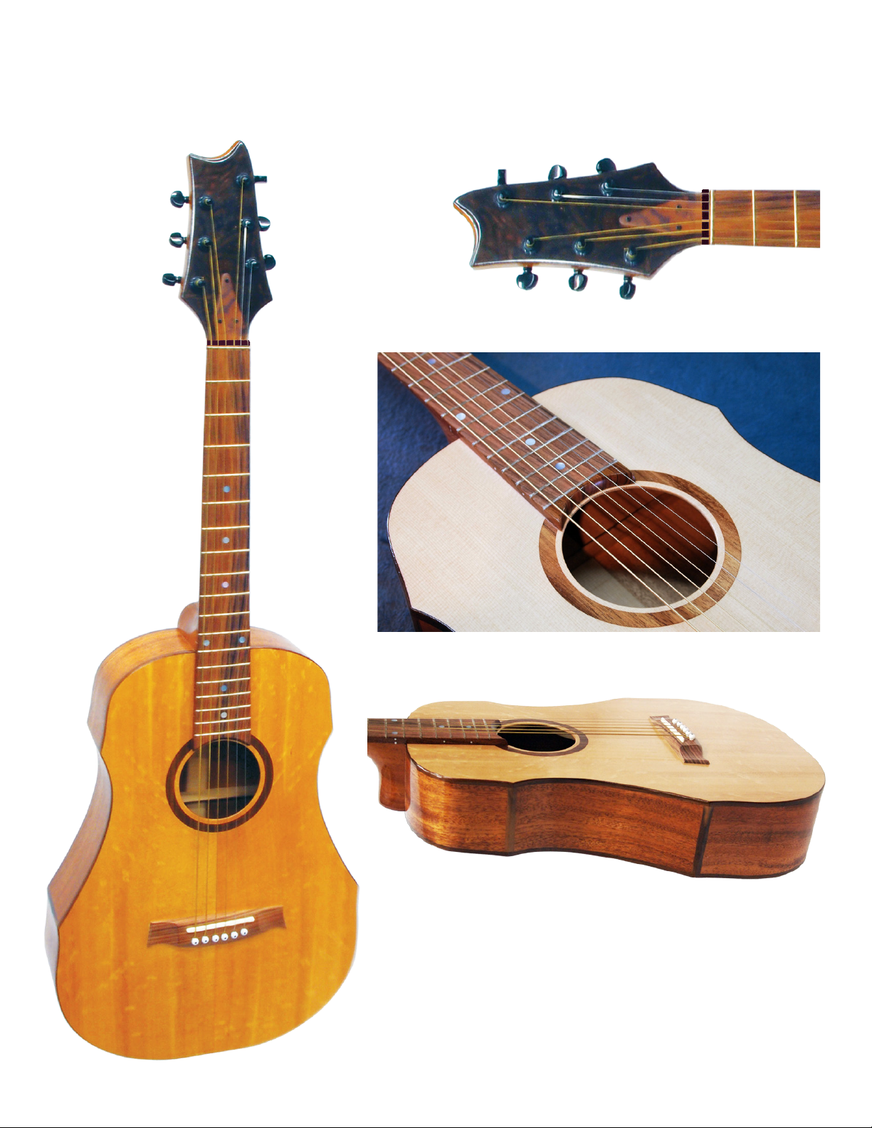
DAKOTA PARLOR GUITAR KIT
MUSICMAKER’S KITS, INC
PO Box 2117
Stillwater, MN 55082
651-439-9120
harpkit.com
Page 2
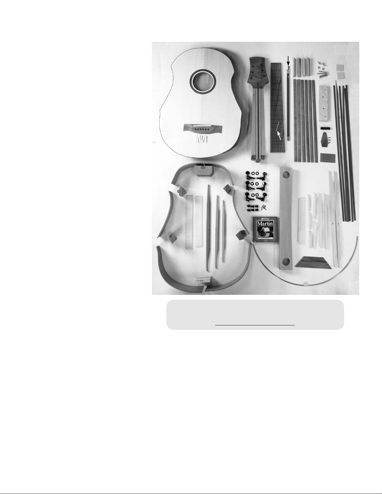
WOOD PARTS:
A - Neck
B - Fretboard
C - Heel Block
D - Tail Block
E - 2 Heel Ribs
F - 2 Side Ribs
G - 2 Tail Ribs
H - 4 Corner Blocks
I - Back Panel
J - 3 Cross-Braces for Back
K - 2 Flat Braces for Back
L - Front
M - 10 Braces for Front (Soundboard)
N - 6 Inner Kerfing Strips
O - Bridge with Saddle
P - Bridge Clamp, w/4 machine screws,
2 washers, 2 wing nuts
Q - Bridge Plate
R - 4 Clamping Wedges
S - Spacer Block
T - 6 Binding Strips, walnut
U - Heel Cap
V - Truss Rod Cover
(Soundboard)
DAKOTA GUITAR KIT
I
L
O
E
C
HH
F
E
F
A
Z
R
P
B
N
X
V
U
T
Y
S
HARDWARE:
K
J
M
W - 48 Inches Fretwire
X - 1 White Side Marker Rod
5/64”” X 2”
H
H
Y - 6 Black Geared Tuners
w/6 sleeves, 6 washers & 6 tiny screws
Z - Double Truss Rod, with allen wrench
1 - Heavy Fretwire, 2” long, for #0 fret
1 - Set of 6 Guitar Strings, light
1 - Black Wood Nut
Fig 1
G
D
G
Q
W
1 - Hex Bolt, 1/4” X 2”, with washer
2 - Tiny Nails
1 - Drill Bit, 1/16” for tiny screws
1 - Drill Bit, 5/64” for Side Markers
1 - Drill Bit, 3/16” for bridge
If you have any questions about the assembly of your
kit - please visit our online Builder’s Forum
www.harpkit.com /forum
Assembly Instructions
A NOTE ABOUT GLUE
We recommend assembling this kit with standard woodworker’s glue (such as Elmer’s Carpenters Glue or Titebond Wood
Glue). Don’t use Hotmelt glue, Superglue, 5-minute Epoxy, or the plain white School Glue for assembling the major wood
parts -- they are not strong enough for a musical instrument. There is no need to look for any special violin-maker’s adhesive.
You may, however, see epoxy or superglue recommended occasionally for installing non-wood parts.
Every time you use wood glue on this project, it is wise to have a damp rag handy for cleaning up afterwards. It is always best
to scrub away any excess glue that squeezes out of the joints before it dries, especially on the outside of the instrument. Keep
your hands and workbench as clean as possible too. Glue smudges will show up vividly on the finished instrument.
ASSEMBLY INSTRUCTIONS
_____1. CAUTION: PLEASE DO NOT OPEN THE SEALED PLASTIC BAG CONTAINING THE FRONT
AND BACK PANELS UNTIL YOU REACH STEP #14. These two parts need to be kept very dry until you glue
the braces on them. Check over your kit parts to make sure you find everything listed (see fig. 1 above). Contact us
right away if you are missing anything so we can rectify the problem without causing too much delay for you. We
also recommend checking off each step in the directions as you finish it. You might be skipping forward to another
part of the assembly while waiting for something to dry, and it helps to keep track of where you left off.
2.
Page 3
GLUING THE BODY FRAME
It is smart to skim through the entire directions before beginning, just to get an overview of the project. You may need to gather
more tools or purchase a few optional decorations or accessories to enhance the finished instrument. Now is a good time to
make those plans so you can avoid delays later. Here are a few of the small items you’ll want to have on hand:
sharp chisel wire cutter 8 spring clamps 2 long-reach clamps for braces
masking tape (blue) clothes pins 8 small c-clamps 40 ft bungee cord (3/16” dia)
carpet tape razor knife triangle file router with flush-trim & inlay bits
straight-edge 6” rat tail file flat mill file wood filler (mahogany color)
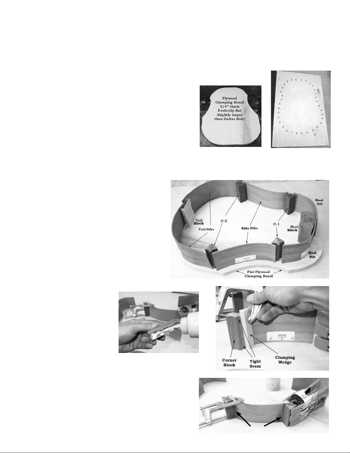
_____2. You will find it very helpful to make yourself a perfectly flat
work surface out of 3/4” thick plywood or particle board for use as a
flat clamping pad under the body of the instrument. If you cut it about
1” larger than the shape of the soundboard, you will be able to easily
fit clamps all the way around the perimeter of the instrument (fig 2a).
Plywood
Clamping Board
3/4” thick
perfectly f lat
about 22” X 28”
Another idea that works well is to use a rectangular piece about 22” X
28” (fig 2b) so you can clamp with bungee cords, as shown in steps 21
and 31. We use both types, as you will see in various photos. Just make
sure the clamping pads are good and flat.
Fig 2a
Fig 2b
CAUTION: IT IS POSSIBLE TO ASSEMBLE THE FRAME PARTS U PSIDE DOWN OR BACKWARDS!
_____3. Carefully arrange the side pieces, corner blocks,
heel block and tail block on your plywood clamping board
to see how they fit together (Fig 3).
CAUTION: Orient all parts so the front edges face downward on your flat clamping board. Notice that we have
marked each side piece, and heel & tail blocks, indicating
the proper orientation.
All front edges are marked “SB” for soundboard, and the
back edges are marked “B”.
The corner blocks do not have a front or back, but they are
numbered C-1 or C-2 to fit the corners with those numbers.
Please take the time to study this carefully so your parts will
fit properly.
ORIENT ALL PARTS WITH FRONT ED GES FACING DOWN
Fig 3
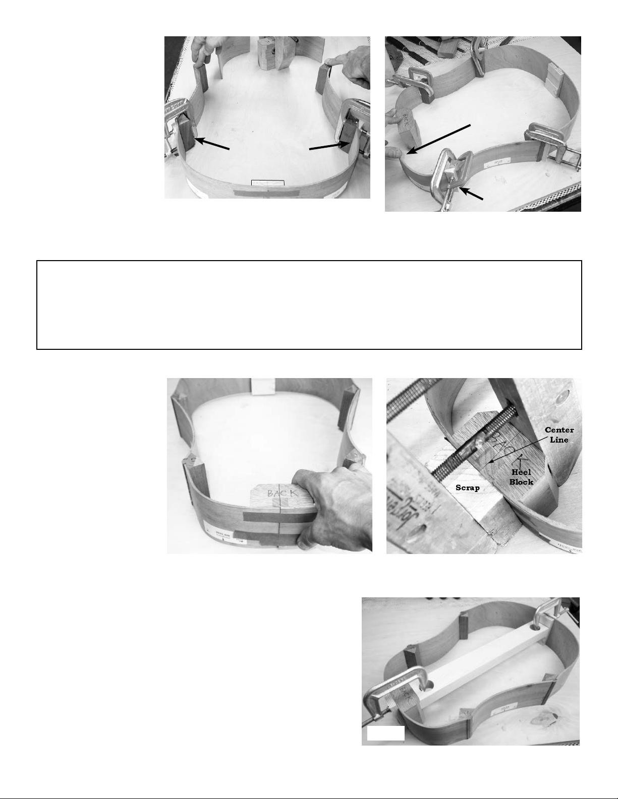
_____4. Begin by gluing and clamping the four corner blocks to the two
side ribs, taking care to orient them
at the correct ends, as printed on the
wood (each side rib gets a C1 at one
end and a C2 at the other end).
CAUTION: The larger part of the
corner blocks will face the inside of
the body, as shown in fig 3. Don’t
Fig 4a
glue them to the outside of the sides!
Clamping wedges are provided to help compensate for the angles of the
parts, as shown in fig 4b. HINT: If you cover the wedges with Scotch
tape, they won’t get stuck to the other parts when clamped.
Use either spring clamps or small c-clamps for this step (fig 4c), making sure the parts are fully seated together and flat on the edges. Use a
wet rag to clean off excess glue that squeezes out. This helps you see
the joints clearly, as well as prevent messy glue spots on the instrument.
3.
Fig 4b
Fig 4c
Clean off excess glue
Page 4
QUESTION
Have you checked to make sure you are still gluing the parts in the correct positions? If you nd a corner block
glued to the wrong end of a rib, you’ll need to correct it now, before proceeding further. You can so en the dried
glue by getting the seam wet to allow the parts to be separated without breaking anything. Be patient with this
process. It may take 10-20 minutes for water to penetrate far enough into the seam to so en the glue.
_____5. While the corner blocks are drying, you can work on
the tail end of the body. Use tape to hold the tail ribs together
as shown in fig 5a.
Find the center of the tail block
and mark it clearly (fig 5b).
Smear glue on the flat face of
the tail block (fig 5c) and place
it inside the seam, as shown in
fig 5d. Find a scrap of wood
to use as a clamping pad for
the outside of the joint, and add
clamps, making sure the block
is oriented correctly and nicely
centered on the seam (fig 5e).
IMPORTANT: Make sure the free
ends of the tail ribs can be pushed down
to the work surface (fig 5e). If not, then
you may have to release the clamps and
slide the parts into better alignment.
Fig 5b
Tail
Block
Fig 5a
Inside surface
of tail block
Fig 5c
_____6. Now you can move to the heel
end of the instrument. Mark the center of
the heel block, on the end marked “Back”
(fig 6a).
Glue this heel block to one heel rib for
now, aligning it to the centerline, as shown
in fig 6b.
Clean up excess glue with a wet rag, as
usual.
Fig 5d Fig 5e
IMPORTANT: Leave the other heel rib
for later. That will be the last step in closing the frame.
Fig 6a Fig 6b
4.
Page 5
_____7. When the corner
blocks are dry, you can remove the clamps and glue
the C2 blocks to the tail ribs,
as shown in fig 7a.
Make sure you can press
the C1 corner blocks down
Check for straightness
by pressing sides down
against clamping board.
Check for straightness
by pressing sides down
against clamping board.
against the work surface
when the side ribs are
clamped to the tail ribs. This
C2 Corner Blocks
ensures a flat frame for gluing the front (soundboard)
in place later.
Fig 7a
Leave the clamps on these C2 joints while you glue the remaining heel rib to
Tail end
Fig 7b
C1 Corner
Block
the open C1 corner, as shown in fig 7b. Leave clamps in place for several
hours to make sure the glue has cured to full strength.
PAUSE AND DOUBLE-CHECK
Before going further, double-check to make sure your parts are still in the correct positions. Do you see “Back”
written on the same edge of all the parts around the frame? If you find something oriented upside-down or backwards, you’ll need to correct it now, before proceeding further. You can soften the dried glue by getting the seam
wet to allow the parts to be separated without breaking anything. If the glue is fully cured, it may take 10-20 minutes for water to penetrate far enough into the seam to soften the adhesive.
_____8. When the four
corner joints have dried
fully, use tape to pull the last
heel rib into place at the heel
block as shown in fig 8a.
Remove the tape so you can
apply glue, and then tape the
parts together again as you
clamp this last joint together
permanently (fig 8b).
Fig 8a
_____9. Once the frame is closed and the glue is dry, you can install
the long spacer block between the heel and tail blocks as shown in fig 9.
This piece will be removed later, but you need it now to hold the frame to
the correct size. Note that the ends of the spacer will fit into the pre-cut
grooves of the heel and tail blocks. Use a clamp at each end to make sure
the heel and tail blocks are held firmly in alignment.
Fig 8b
Spacer block
5.
Fig 9
Page 6

_____10. Flip the instrument over (soundboard edge up) so you can fit kerfing inside the frame. Cut a length of kerfing to fit
between the corners and blocks inside each rib (fig 10a & 10b). We like to cut these strips a little oversize and then sand them
to fit nicely into the corners, as shown in fig 10c and 10d. CAUTION: Be sure to orient the kerfing with the flat side up. level
with the top edge of the ribs.
Fig 10a
Fig 10c
CHECK-POINT: You should be installing the kerfing on
the soundboard edge of the frame. You should see “S.B.”
written on the ribs at this edge of the frame all around.
We use spring-type clothes pins to clamp the kerfing in place
(fig 10e), but you may find some other small clamps to pinch
the parts together while you glue these kerfing strips in place.
If necessary, you can increase the clamping pressure by wrapping rubber bands around the clamps as we have.
Work your way around the soundboard edge of the frame
with the kerfing, but don’t do the back edge yet -- that will
be easier to do later.
Fig 10b
Fig 10d
Fig 10e
_____11. OPTIONAL: You can reduce the weight of your guitar a little by trimming off the large inside corners of the corner
blocks, as shown in fig 11a. This step is optional, but it is recommended.
The illustration shows a chisel, but we use a power drum sander to do this job more quickly. You’ll want the corners to be
trimmed so they blend in with the thickness of the kerfing, as shown in fig 11b.
NOTE: If you decide to leave the corner blocks full size, you should at least bevel the tops of the inside corners by sand-
ing them at an angle so they
won’t touch the soundboard
(fig 11c). This helps prevent
cracks in the soundboard
later, and allows for a little
more vibration in the top.
bevel
Fig 11a
Fig 11b Fig 11c
6.
Page 7
_____12. This is a good time to open up the slot for the tenon
in the heel block so it looks like fig 12a below. You could do
this by hand with a sharp chisel and/or razor knife, but we use a
router with a flush trim bit (fig 12b). The goal is to trim away
all rib material that covers the pre-cut slot in the heel block.
Fig 12a Fig 12b
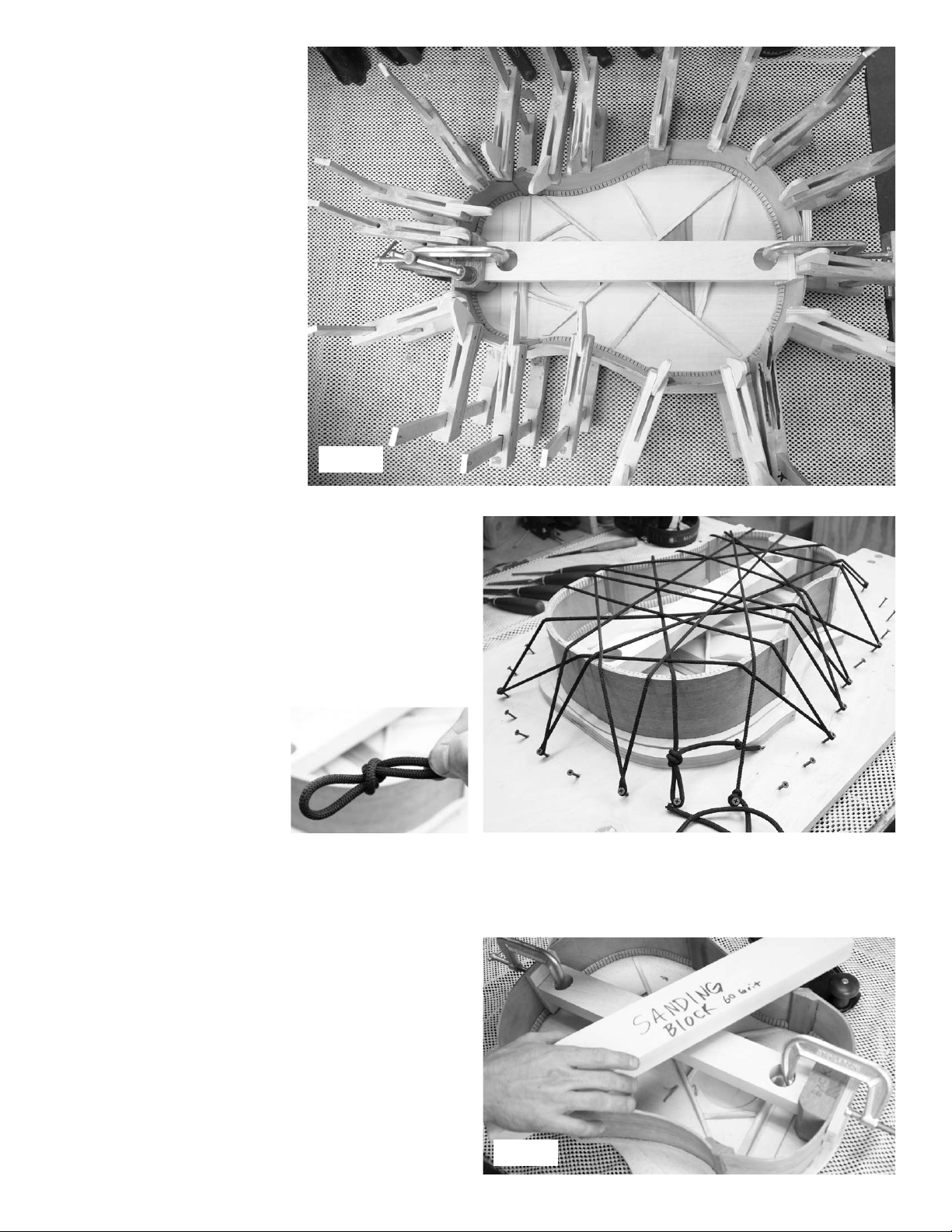
_____13. Make yourself a long sanding block now, using a flat board about 2-3” wide and at least 16” long.
Apply double-stick carpet tape to the flat face of the
sanding block, covering the face the full 16” length (fig
13a).
Cut coarse sandpaper (60 grit) to match the width of
the board and press the clean side down against the tape
(fig 13b). You can add to the length of the sandpaper by
pressing a second piece in place at the end of the first.
Pencil hash-marks on the kerfing around body, as shown
in fig 13c.
Fig 13a
Fig 13b
Then use your flat sander to level the entire front edge of the
frame. Keep the sanding block flat by always having both ends
resting across the instrument, as shown in fig 13d.
The pencil marks should all be cleaned off by this sanding work.
Keep sanding until they are all removed.
Fig 13c Fig 13d
7.
Page 8
PREPARING THE SOUNDBOARD
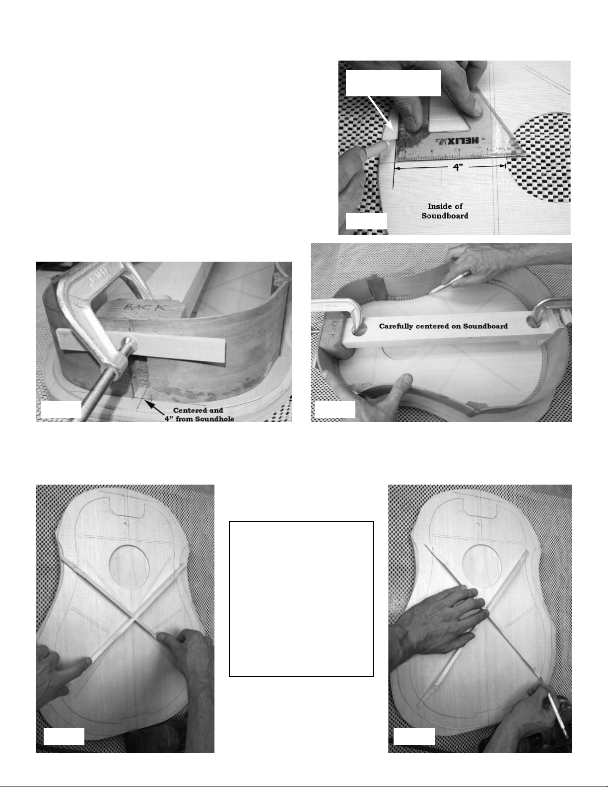
_____14. Now you can open the sealed bag and begin working on
the soundboard. First thing is to outline the inside of the frame on the
inside face of the soundboard so you know how to trim the braces.
We have marked the location of most of the braces in pencil, but
there are a few things you need to draw. Begin with making a line 4”
from the sound hole and perpendicular to the center line, as shown
in fig 14a.
Center the frame of the guitar on the centerline of the soundboard,
lining up the heel end with your pencil mark (fig 14b).
Then draw a pencil line around the inside of the frame to show where
the kerfing touches the soundboard (fig 14c).
draw line to mark
heel end of frame
Fig 14a
Fig 14b Fig 14c
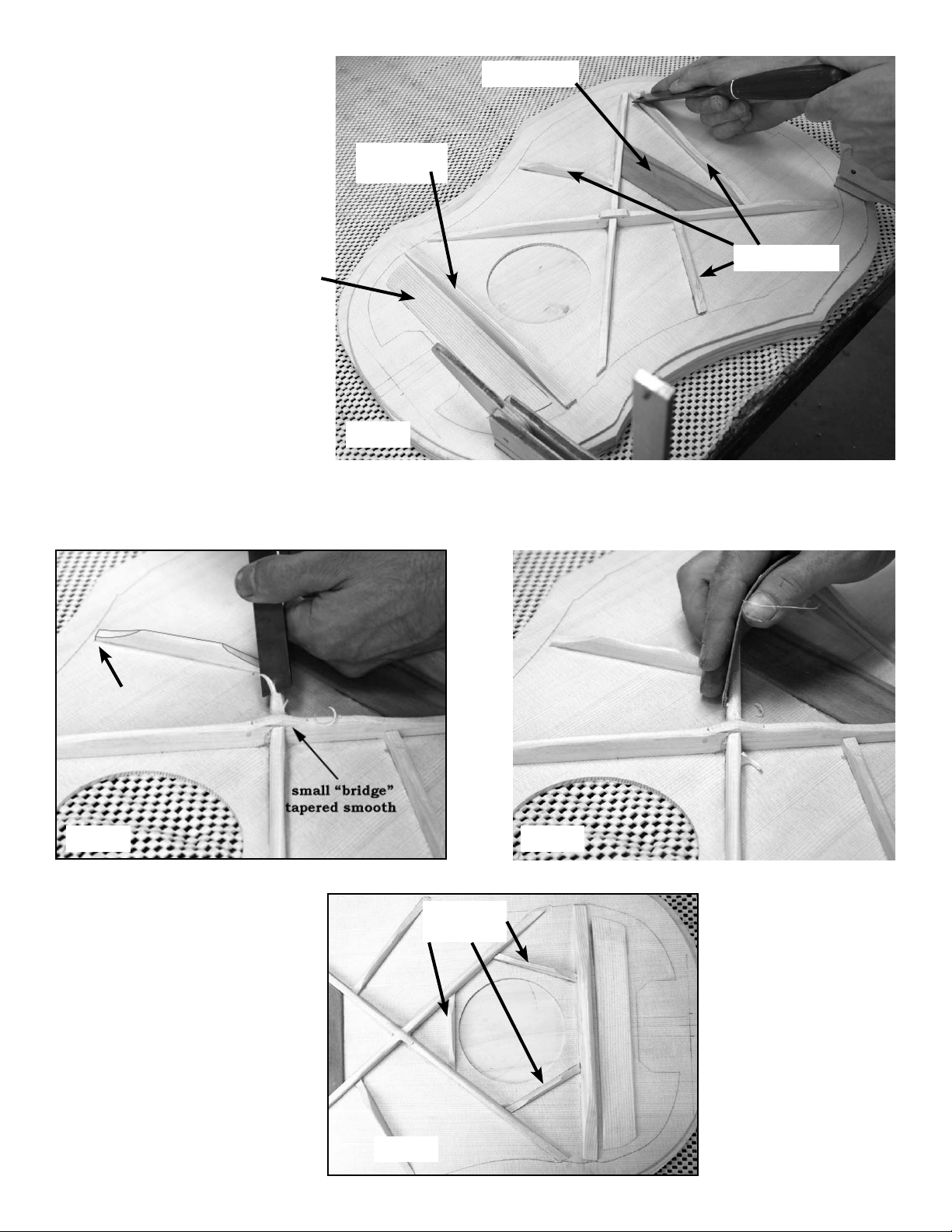
_____15. Find the two X braces and connect them together in the middle. Note that there is a wrong orientation for these
braces (fig 15a). When properly oriented, the X will match the outline on the soundboard, as shown in fig 15b. Center the X
on the soundboard and mark where the ends of the braces cross your outline of the frame.
WRONG RIGHT
POINT OF INTEREST
Some purists will leave these
braces long enough to fit into
“pockets” that they cut into the
kerfing. This is difficult to do
well, but helps prevent a brace
from breaking free at one end
due to future abuse. We provide bracing long enough to allow you to choose this method
if you wish, but it will increase
your working time a bit.
Fig 15a Fig 15b
8.
Page 9

Mark and trim these
braces to the pencil
line, as shown in
fig 15c and 15d.
(or cut them a little
longer if you plan to
cut pockets for them
in the kerfing)
Fig 15c Fig 15d
_____16. Before gluing the X braces in place, test your clamping system without glue to make sure you have sufficient pressure
everywhere. You want even pressure across the full length of the
braces. Make sure that the ends will be pressed fully against the
soundboard. You don’t want these braces to come loose!
When all is ready, glue and clamp them in place to the soundboard, pressing them against your flat clamping board. NOTE:
be sure to put glue in the notch where the two braces intersect.
Use the spacer block (or other long scrap) across the soundboard
to press the intersection firmly (fig 16).
Wipe off excess glue and leave the clamps in place for 3-4 hours
until dry.
_____17. When the braces are dry, use a chisel to clip a 1/4” end of the
thin flat back bracing material to use for a patch across the intersection of
the X braces, as shown below (fig 17a).
Glue and clamp this patch across the intersection forming a “bridge” to tie
the bracing together firmly (fig 17b).
Fig 16
Fig 17a Fig 17b
9.
Page 10
_____18. Mark and trim all but the
three shortest braces, and glue them
in place where they are marked on the
soundboard (fig 18).
bridge plate
NOTE: Hold off on the three short
soundhole braces for now. It is easier
to shape and sand the larger braces before installing the short ones.
additional
top brace
_____19. Use a sharp chisel to round over tops of braces
and to taper ends to about 1/8” high around the perimeter
of the soundboard (fig 19a).
transverse
brace
Fig 18
finger braces
Switch to medium sandpaper (150 grit) to smooth the
tops of all braces (fig 19b).
1/8” high
at end
Fig 19a Fig 19b
_____20. Fit and glue the three shortest braces around soundhole, as shown
in fig 20.
Fig 20
soundhole
braces
10.
Page 11
GLUING THE SOUNDBOARD
_____21. Be sure to keep the spacer block firmly clamped to the frame
for this operation! This will help
hold the shape of the body as you
apply clamps.
Test-fit the frame on top of the
soundboard without glue first, to see
how the braces fit inside the kerfing.
Trim the braces as necessary.
NOTE: If you plan to cut pockets
into the kerfing for the ends of the
main X braces, this will take some
time for trial and error fitting.
Plan out your clamping method and
assemble enough clamps (or Bungee cording) to do the job before
you begin.
spacer block
We show two ways to clamp the
body down against the soundboard:
20 clamps, as shown in fig 21a, or 20 feet of light bungee cording (available from Musicmakers), as shown in fig 21b.
If using the Bungee cord method, put screws around your flat
work surface at an angle, about 2-3” apart, for wrapping the
cord. If you didn’t make a 22” X 28” clamping board, you can
put the screws in the edge of your smaller plywood instead of
4” away from the guitar as shown.
When ready, spread glue all around the edge of the guitar frame
(including the kerfing), and put the frame back on the soundboard, making sure there are no obstructions preventing a nice
flat fit.
If using Bungee cord, tie a loop at
one end, hook it on a nail and work
your away cross the instrument in
spider web fashion to press the
entire frame down firmly against
the soundboard (fig 21b).
Fig 21a
Fig 21b
PREPARING THE BACK
_____22. When the soundboard is dry, remove the clamps and
turn the instrument over so you can start working on kerfing
for the back edge. Begin by leveling the edges of the ribs and
corner blocks, using your long flat sanding block (fig 22).
The goal is to eliminate glue blobs and other irregularities that
will interfere with a good fit of the back panel. You’ll be sanding more after the kerfing is installed, but you’ll use a curved
sanding block next time.
HINT: Leave the spacer block in to stablize the frame as you
sand, until you get to the heel and tail blocks. You’ll need to
remove the clamps in order to sand those areas.
Fig 22
11.
Page 12

Fig 23
_____24. Turn the body over onto the inside of the back
panel and center it carefully on the centerline. Draw around
the outside of the frame with a pencil, as shown in fig 24.
_____23. Now you need to install kerfing all around the back
edge of frame, just as you did on the front edge earlier (fig 23).
CAUTION: Don’t sand this kerfing with the flat sanding
block. You will make a curved block for this because the
back is arched (see step #30).
Fig 24
_____25. Set a compass to match thickness of the back
edge with kerfing, as
shown in fig 25a.
Then use that setting
to draw the inside
outline on the back
panel, as in fig 25b.
Fig 25a Fig 25b
_____26. Measure where the heel block and tail
block will fit on the back panel.
The heel block extends 1-3/4” (44.5mm) in from
the outer edge of the frame, as shown in fig 26a.
Fig 26a
The tail block extends just 3/4” (19mm) in from
the outer edge at the tail end of the frame, as in
fig 26b.
These two lines will help you place the the flat
back bracing that goes down the centerline to reinforce the glue seam in the back panel.
Fig 26b
12.
Page 13

_____27. Notice that only one brace is outlined on the back panel, but there are little circles drawn to show the ends of the other
two braces. Connect those circles with a straight edge to mark the location of the other two braces, as shown in fig 27a.
Find the three back braces and mark where to trim them so they don’t
interfere with the back kerfing (step 27b).
Trim braces
to length (or
fit the ends
into the back
kerfing), as
before.
_____28. Notice how the underside of
the back braces are curved. This curve
matches the 15’ (4.57m) radius curve
on one edge of the spacer block (fig
28a).
This means you can use the spacer
block to support the clamping pressure
when gluing each brace in place, thus
forming an arched back panel.
Make sure you have at least one clamp
that will reach to the middle of the
brace, as shown in fig 28b.
When ready, glue each brace in place
separately, being careful to center it on
the centerline over the outline you drew
for that brace in the previous step, and
supporting it with the curved side of
the spacer block underneath.
Fig 27a
Fig 28a
Fig 27b
_____29. When all three back braces
are dry, find the flat back braces and
mark and cut them to fit between the
other braces, to cover the center seam,
as shown in fig 29a.
It is best to sand these parts before
gluing them in place. They look best
when the top surface is sanded smooth
and the top edges are rounded over
gently (fig 29b).
Fig 28b
Fig 29a Fig 29b
13.
Page 14

Balance the back panel on a long flat board beneath the centerline to support this pressure. Use long clamps or weights to press
these braces in place with glue (fig 29c). Add scrap wood under the clamps to distribute the pressure evenly over this flexible
flat bracing. Notice the end braces are cut just short of the pencil line marking the heel and tail blocks (fig 29d).
Fig 29c Fig 29d
_____30. Put double-stick carpet tape on the curved edge of
the large spacer block that was holding the frame (fig 30a).
Fig 30a
Use this curved sanding block to shape and smooth the back
edge of the instrument frame, as shown in fig 30c.
PLEASE NOTE: Keep the sanding block oriented across
the frame as shown, perpendicular to the centerline of the
body. This is the direction of the curve in the back panel,
and it will give you nice firm glue joints around the perimeter of the frame when clamping the back in place.
Then cut strips of coarse (60 grit) sandpaper to fit along the
edge and press the paper against the adhesive tape (fig 30b).
You may need to butt two strips end-to-end.
Fig 30b
Fig 30d
Fig 30c
Turn the frame over on top of the back panel and check carefully
to see that the braces do not interfere with the kerfing (fig 30d).
Take your time with this. Trim any braces that are too long to
fit inside the frame. If you end up applying clamping pressure
to an area where the braces are in the way of the kerfing, you
might break something!
14.
Page 15

_____31. Turn the frame back-side-up and arrange it on
your work surface. Apply glue to the back edge, all the way
around the circumference, including the kerfing, heel, tail,
and corner blocks.
Carefully position the back panel on top, nicely centered at
each end, and apply clamping pressure. If using individual
clamps, we recommend placing clamps at the heel and tail
ends first to hold the back on the centerline, then work your
way around the circumference with more clamps. Check the
seams by looking under the overhang of the back to make
sure it is fully pressed down all the way around.
If using the Bungee cord clamping system, put screws all
around the frame, about 4” away from the body, and spaced
about 2-3 inches apart, as shown in fig 31a.
Place the back panel carefully centered on the frame and
begin pulling Bungee cording across, making sure the back
does not slide out of position as you work. We show two
20-ft lengths of Bungee cords, 40 feet (10 m) total, in the
photo at right (fig 31b).
Fig 31a
Be sure to check around the entire glue seam, looking under
the overhang and pressing down to see if there is any section that is not held firmly. Watch for glue squeezing out of
the joint -- that’s a good sign of sufficient pressure.
_____32. When dry, trim off the excess overhang
of the soundboard and back flush with the outside
of the body.
We like using a flush-cutting router bit (fig 32a)
for this step. Move the router clockwise around
the instrument (this is called “climb cutting”) to
minimize the chance of chipping the thin spruce
top and mahogany back panels (fig 32b).
You can achieve the same results more slowly using a coping saw to cut close to the sides, and then
a sanding block to sand it flush.
The corner blocks protrude a little beyond the sides, so you’ll want to sand those flush too.
A spindle sander or attachment to a drill press works well for this (fig 32c), but you can also
make a curved sanding block using a tin can or other round object to wrap your sandpaper
around (fig. 32d). Always watch closely to make
sure you don’t distort the shape of the corners.
Fig 32a
flush-cutting
Fig 31b
router bit
Fig 32b
This is an important step for achieving a nice-looking guitar. The corner blocks and sides should meet
seamlessly and smoothly.
If you find gaps in the joints, fill them with mahogany colored wood filler, available from most hardware
Fig 32c Fig 32d
stores. Or make your own paste of mahogany sanding dust and Superglue.
14.
Page 16

_____33. OPTIONAL DECORATING: If you have a router, you can install
binding around edges of the guitar. This is not a necessary step, but it adds
a lot to the appearance of the finished instrument. Use our Inlay Router Bit
with the smaller bearing for this operation. Set the depth of cut to match the
width of the binding strip, as shown in fig 33a.
Make a test cut in a
scrap of wood, and
check the fit of the
Fig 33b
binding strip (fig 33b).
Be careful not to
“fall” into the
slot for the tenon
Use the router to cut a ledge all the way around the top and bottom of
the instrument for inlay strips, working clockwise around the perimeter, as before (fig 33c). The roller bearing will prevent the router bit
from cutting too deeply. You may need to go around the instrument
twice, just to make sure the ledges are cut to full depth.
Wet the wood binding in a tub of warm water for just
1-2 minutes before bending it around the guitar.
cutter height matches
width of inlay strip
Fig 33a
Fig 33c
Fig 33e
SANDING
BLOCK
Fig 33g
Bend one long strip
around the tail end
of the instrument,
holding it in place
with a few pieces
of tape.
Fig 33d
Mark the length and
trim it close with a
chisel or razor knife
(figs 33e & 33f).
CHISEL
Fig 33f
BINDING STRIP
Then test-fit again using a sanding block to make small adjustments to the ends until they
are just the way you want them (fig 33g). We like to make mitered joints in the binding
at each corner block (fig 33h), but that can take some extra time. An easier option is to
make “lap” joints instead (fig 33i).
For lap joints you would install the first piece a little longer than necessary and trim it
off after the glue dries, sanding the end to match the next ledge. Then your next piece
MITERED
JOINT
LAP
JOINT
can also be longer than
needed, so you just
trim it off and sand it
flush with the outside
edge of the first binding piece.
Fig 33h
Fig 33i
16.
Page 17

Once you have planned your joint, you can apply glue to the
groove and use lots of masking tape to hold the binding in place
until dry (fig 33j). Be sure to pull the binding fully into the slot as
you tape it.
HINT: Think of the tape as being somewhat elastic (even though
it isn’t). That helps you use a pulling action as you install it.
Cut binding to fit the next section of the guitar (fig 33k). Glue and
tape it as before.
Fig 33k
Fig 33j
When you get to the heel end of the top (soundboard), you can
leave the trim a little short because it will be covered (hidden) by
the neck and fingerboard (fig 33-l).
Fig 33-l
The back binding is easier to install in a different sequence. It
is best to install one long piece of binding for the heel end just
as you do for the tail end (fig 33m). Notice that the binding at
heel end of the back will not be covered when you install the
neck, so you don’t want any gaps in the back binding.
Fig 33m
Once the binding is installed and dry, remove all the tape, being careful to
avoid lifting the grain of the spruce soundboard. HINT: Pull slowly, and
if you see any damage starting, pull in the other direction from the
opposite end of the tape.
Then you can fit the two side bindings in place last around
the back side.
When the tape is all off, do some sanding to eliminate all glue residue
around the instrument. The tape has a nasty tendency to smear excess
glue over wide areas, but it is relatively easy to sand off with medium
(100-150 grit) sandpaper.
We even use a hand orbital sander for some of this work (fig 33n), though
you need to be careful not to sand too deeply when you use power equipment.
17.
Fig 33n
Page 18

PREPARING THE FRETBOARD
_____34. ANOTHER OPTIONAL STEP: You can trim the width of your fretboard to
suit the grip of your left hand. Most production guitars measure about 1-3/4” (44-45mm)
wide at the narrow end (by the “nut”), and 2-1/4” (57mm) wide at the 12th fret. You’ll
notice that we supply slightly wider parts in this kit to allow someone to make the neck fit
a larger hand.
If you want to trim the width a little
bit, be sure to draw a straight line
along one or both edges to mark the
final desired width (fig 34a). Then
you can use a block plane or coarse
sanding block to remove the excess
material (fig 34b).
Fig 34a
_____35. YET ANOTHER OPTIONAL STEP: You may sand a small
radius into the top surface of the fretboard if you wish. Most production
steel-string guitars have about a 15” (38cm) radius on top of the fretboard.
This is quite easy to do with either a block plane or a coarse sanding block.
Begin by putting double-stick carpet tape at each end of the underside of
the fretboard, as shown in fig 35a.
Stick the fretboard to your work surface and use your block plane or sanding block at a tilted angle to remove some material from each side along the
entire length of the fretboard (fig 35b).
Use a pencil on the end of a 15” string to draw the desired arc onto a stiff
notecard. Cut on the curved line and check your progress by holding the
card against the wood (fig 35c).
Fig 35b
Fig 34b
Fig 35a
Fig 35c
POINT OF INTEREST
The fretboard radius can vary from 7.5” to 20”, depending on your playing preferences. The tighter radius is more comfortable
for the curvature of your hand, but a flatter radius is better for fingerpicking and for bending notes. In fact, classical guitars
(nylon strung) have flat fretboards, no radius at all. It is also possible to achieve a compound radius in which the fretboard
resembles a slice off a cone. This gives you a tighter radius at the nut and a flatter radius near the body of the instrument. Such
a shape actually fits the natural plane of the strings. So you can work your fretboard to suit your playing style.
Hold a straight-edge against the fretboard to make sure the wood is still straight across the top from one end to the other (fig 35d).
You don’t want any depressions or high spots in the playing surface. Use a coarse sanding block to do the major leveling (fig 35e).
Fig 35d
_____36. OK, HERE’S ANOTHER OPTIONAL STEP: Many people like the appearance of having pearl inlay dots in cer-
tain spaces on the top of the fretboard to guide their playing. We have included white side markers for the fretboard, but you may
also purchase 1/4” diameter pearl dots from Musicmaker’s if you want to inlay them on the top surface as well. It is common to
see from 5 to 7 marking dots located in the spaces shown in fig 36a (numbering the spaces from the narrow end of the board).
Fig 35e
18.
Page 19

Fig 36a
Draw a centerline down the fretboard and use an awl to punchmark the locations of the marking dots, as shown above.
Then use a 1/4” drill bit to bore shallow holes (1/16”, or 2mm deep) at each punch (fig 36b).
Glue each dot with a drop of 5-minute epoxy or Superglue (CA adhesive) (fig 36c), and press
or tap it down into the hole (fig 36d). A scrap of wood works well to pad the dot (and the
surrounding wood) from your hammer. Ideally, you can push it close to level with the top
surface, but it is fine to have the dots stand a little higher than the wood. You’ll sand them
down flush after they dry.
Fig 36d
Fig 36c
_____37. Use your coarse sanding block to level the dots with the wood. Then you can smooth the entire top surface of the
fretboard with progressively finer sandpaper in this approximate sequence: 100 grit, 180 grit, 240 grit, 320 grit, 400 grit, and
finally 600 grit.
Fig 36b
2mm
deep
1/4” drill
POINT OF INTEREST
This final sanding should leave the fretboard silky smooth, almost as if it were finished and polished. Your fretboard is made
from Bolivian Rosewood which has natural oils that seal the pores, so there will be no need to apply a surface finish over the
top. Your sanding at this point will give you the final playing surface.
_____38. Now you are ready to install the frets. IMPORTANT: Begin by finding the special #0 fret in your parts pack-
age. This short piece of fretwire has a little fatter bead than the rest, and it must be placed in the very first slot at the
narrow end of the fretboard to hold the strings at the proper height.
Clip that #0 fret slightly longer than necessary to reach across the narrow end of the board (fig 38a). Notice that the fretwire is
shaped with a rounded cap that stays on top of the wood, and a thin tang that will fit tightly down into the pre-cut slot.
Use a small hammer to tap one
end of the tang into the slot, and
work your way across to the
other end of the fret, checking
to see that it is fully seated along
the way. It should go easily, requiring only 4-8 taps for each
fret (fig 38b).
Continue the same process
with the rest of the fretwire until all of the frets are installed.
Double-check carefully, under
good lighting, to make sure the
frets are fully seated against the
wood. Tap them down further
as necessary.
The ends of the frets need to be sanded flush and smooth with the sides of the
fretboard. This goes quickly if you hold the fretboard up against a belt sander, but
you can also use a fine flat file or a sanding block with time and some effort. Once
the ends are flush with the wood, tip the file (or sandpaper) to bevel the ends of
the frets about 45 degrees, as shown here (fig 38c). Check how smooth it feels by
running your hand along the edges of the fretboard. Be sure to eliminate all sharp
points and roughness.
Fig 38b
Fig 38a
bevel
Fig 38c
#0 fret
frets
19.
Page 20

PREPARING THE NECK
_____39. Temporarily clamp the fretboard to the neck, carefully centering it and
leaving enough flat space at the narrow end to allow for the ebony nut. Use a
pencil to outline the fretboard as shown in fig 39a. These lines will be helpful
reference points as you do more shaping on the neck to fit your grip.
Remove the temporary clamps and set the fretboard aside while you work on the
neck. We like to clamp the neck upside-down and hanging over the edge of our
work table, as shown in fig 39b. This allows you free use of both hands for doing
some shaping at the heel with a rasp and/or coarse sandpaper.
When the shape looks rounded enough for you, switch to medium (100-grit) sandpaper to smooth out the surface (fig 39c). This area will be difficult to sand when
the guitar is assembled, so take the time to do it now.
Fig 39a
Fig 39b
Fig 39c
CAUTION: Be careful not to damage or remove the thin edges at the heel of the
neck. You can reduce their width to match your fingerboard, but leave them full
height to make it easier to fit the neck to the body.
In these directions, we will refer to the four corners of the heel as A, B, C, & D, as
shown in fig 39d, to help you plan your adjustments.
Chamfer the edges of the slot in the heel of the body for the tenon to make sure
the sharp corners don’t interfere with the tenon fitting all the way into the slot. A
chisel or file works well for this task (fig 39e).
Test-fit the neck to the body. If the tenon is too tight for an easy fit, you can file it on
one or both sides, as necessary, but try to avoid making it too loose and sloppy in the
slot (fig 39f). Check for glue residue in the slot that might interfere with a good fit.
TENON
SLOT
C
Fig 39d
HEEL
BD
A
Fig 39e
TENON
Fig 39f
20.
Page 21

_____40. Before doing more fitting of the neck to the body, it is best to
use your flat sanding block to make sure the heel end of the body is flat and
level (fig 40). Try to keep the sanding block from rocking too much as
you work on the end of the guitar. You should not have to remove much
material, but you want to get rid of irregularities in the surface, like glue
blobs, bumps, and depressions in the wood.
_____41. Test fit the
neck to the body again.
Find the bolt and washer for holding the neck
to the body, and use a
7/16” socket wrench
to draw the parts together from inside the
body, as shown at right
(figs 41a and 41b).
Fig 41a
HINT: When you assemble the neck
to the body, you should be able to slide
the neck up or down about 1/16” to
get the top of the neck level with the
top of the soundboard.
Fig 40
Fig 41b
If that isn’t quite enough adjustment for
your parts, you can remove the neck
and use a round file to elongate the hole
in the heel block a little bit to allow the
bolt to move up or down further (fig
41c). This would be easier than doing a
lot of sanding on the top surfaces!
Your goal is to have the neck aligned with the
centerline of the body (fig 41d), and level with
the soundboard. Use a straight-edge to check
these details.
Notice (fig 41e) that our neck tilts downward
from the plane of the soundboard, leaving a gap
under the straight-edge, so we need to adjust the
heel to level those parts together.
Your parts will likely be different, so you can
adapt these instructions to achieve your goal.
The neck at right (fig 41e)
slopes down ward toward
the peghead, so it needs
a little adjustment at the
heel to raise the peghead
end and remove the slope.
We want the surface of the
neck and soundboard to be
level and flat.
Fig 41e
Fig 41c
Elongated
hole
Center Line
Fig 41d
No gap here!
In the next step we show
how to accomplish this type
of adjustment.
21.
Page 22

POINT OF INTEREST
Many guitar builders angle the neck down a few degrees from the plane of the
soundboard on purpose to help lower the string action, but on this kit, we have
sloped the fretboard to accomplish the same result. This makes your kit easier
to assemble, with less guess-work. So all you need to worry about is to achieve
a level playing field along the top of the guitar from the tail end to the peghead.
_____42. For our situation shown earlier, we need to carefully shave the thin
edges of the heel to slope them slightly lower toward the corners marked A and
C, as shown in fig 42a.
We like using a flat sanding block for this careful work, checking the fit frenquently to make sure the parts are fitting better and better as we go.
Once the neck is flat with the soundboard, you
need to make sure it lines up with the centerline
on the body (fig 42b).
Use the bolt to hold the neck in place as you lay a
straight-edge down the center of the neck to see
how it aligns with the body.
If it is off, sand one side of the heel a little further
to straighten the neck. Be sure to keep track of
which side needs work! Use your A, B, C, & D
marks (fig 42c).
A
Fig 42a
Fig 42c
Assemble the parts again and double-check for
any unevenness along the top surfaces where
the neck meets the body. You will want the
fretboard to fit nicely across this seam, so use a
sanding block if necessary to remove any irregularities in those surfaces (fig 42d). This should
only require light sanding.
Fig 42b
ADDING THE FRETBOARD
_____43. Now you are ready to glue the fretboard to the
neck. Begin by centering the fretboard on the neck, leaving sufficient flat space at the narrow end (near peghead)
for the “nut”. Pencil the outline of the fretboard so you can
easily re-position it in the same spot (fig 43a).
Fig 42d
space for
“nut”
22.
Fig 43a
Page 23

We recommend installing two tiny nails partway into the neck: one near each end, as shown in fig 43b. Clip the nails close to the
wood (fig 43c). These studs will help prevent the fretboard from slipping out of position as you glue and clamp it to the neck.
Fig 43b
_____44. Push the truss
rod into the slot in the neck,
with the barrel nut facing the peghead (fig 44).
HINT: We like to orient
the truss rod so the adjustment barrel nut rests at the
bottom of the slot instead of
the top. That is the normal
orientation on production
guitars.
_____45. Carefully place the fretboard back over the neck, aligning it with your
outline, and leaving enough flat space for the “nut” near the peghead, and press
the fretboard firmly down against the neck, especially where the tiny nails are
located (fig 45a). This will create pin-pricks under the fretboard to keep the
parts from sliding out of position during gluing.
Get some clamps and scrapwood ready for clamping the fretboard onto the
neck. Look at the following photos to see how we press these parts together.
Barrel nut for
adjustment
Fig 44
Truss Rod
Fig 43c
space for
“nut”
Fig 45a
When ready for gluing and clamping, squirt
glue on the neck, as shown in fig. 45b
space for
“nut”
Replace the fretboard on the neck so the tiny
nails “fall” into the pin-prick dents made earlier.
Remember to leave enough flat space at the peghead end for the “nut”.
Notice the scrap
wood pads
under the metal
c-clamps. These
are important for
protecting the
instrument wood
from dents
Fig 45c Fig 45d
(figs 45c & 45d).
23.
Fig 45b
Page 24

_____46. The peghead can be shaped a little further at the end if you want to customize
the instrument that way. Just make sure you don’t interfere with the fit of the geared tuners
by removing too much material. We use a band saw and spindle sander or drum sander for
this kind of modification (fig 46a).
You can also trim the end of the fretboard to fit the sound hole. Bolt the neck back onto the
body and use a short pencil stub to outline the edge of the sound hole on the underside of
the fretboard, as shown in fig 46b. Use a band saw or coping saw to cut close to the curve
(fig 46c), and then a drum sander or curved sanding block to smooth it out to the line, or a
little beyond. It is OK to have the fretboard fall 1/8” short of the sound hole. We also like
to bevel the curved end, or round over the top edge a little. Just check how it looks on the
guitar, and work on it until you like the results.
Fig 46a
Fig 46b
Fig 46c
_____47. Now it is time to do final shaping and sanding of the neck and fingerboard assembly. We like to clamp it upside-down
at the heel so we have both hands free for filing, sanding, scraping, etc. (fig 47a). The goal is to reduce the thickness until it feels
good in your hands for playing. If you don’t play guitar, you might ask a musical friend to help evaluate the neck for comfort.
Use a rasp for removing material quickly. Then switch to sandpaper to smooth things out and remove the coarse file marks.
Work carefully near the peghead to round things over and
smooth out the curves (fig 47b.
Fig 47a
We like to shape the thinnest part of the neck (near the peghead) to about
1 - 3/4” (44 mm)
Fig 47b
7/8” (22mm) thick, including the fretboard, and 1-3/4” (44mm) wide.
We also like the back of the neck to be shaped somewhere between a V and
a U, so it does not seem “boxy”. Here is a drawing of the cross-section we
Cross-section
of neck
7/8” (22 mm)
like at about the first space next to the peghead (fig 47c).
24.
Fig 47c
rounded
“V” shape
Page 25

Fig 48
_____48. When you have the neck shaped to your liking, smooth everything off with medium
sandpaper (about 100-150 grit). Check carefully for scratches from your coarser tools, and
sand with the grain direction wherever possible (fig 48).
_____49. OPTIONAL: Some players like having side-marking dots on the fretboard for easier
reference from the player’s perspective. The most common positions are shown in fig 49a.
Fig 49a
Use a sharp awl to punch-mark the placement for
the marking dots so your drilling will be accurate.
Then use the 5/64” drill bit included with this kit
for drilling holes about 1/8” deep along the edge, as
shown in fig 49b.
You don’t really need to glue the white stick into
the hole if it is a tight fit, but Superglue will work
fine if needed. Clip off the excess as you move
from hole to hole.
Fig 49b
____50. Before you proceed to installing the neck permanently, it is smart to sand the
soundboard now when the fretboard is not in the way. Use a sanding block with fine
(180-220 grit) sandpaper to smooth especially the area where the fretboard will cover
(fig 50).
This is also a good time to use sandpaper to round over the inside edges of the sound
hole, just to remove splinters and make it smooth to the touch.
____51. Prepare for the gluing operation by having the bolt, wrench, small c-clamp, and
a scrap of wood to use as a clamping pad, as shown in fig 51b on the next page. Then
you can carefully put glue on just a few places at the heel of the neck and under the
fretboard, as shown here in fig 51a. If you overdose here, you’ll end up with a lot of
messy cleanup, and the extra glue will not make the guitar any stronger.
Use a sharp blade or razor knife to trim flush, and
follow up with a sanding block to smooth the area
(fig 49c).
narrow edges that you fitted earlier
both sides of tenon
Fig 49c
Fig 50
near edges of fretboard
POINT OF INTEREST
Some luthiers say that gluing just the edges of the the fretboard to the soundboard
may help prevent shrinkage and/or stress cracks in the spruce later on. It also facilitates removing the fretboard from the soundboard if repairs are needed.
25.
Fig 51a
Page 26

Quickly slide the neck into place and install the bolt to pull the parts together. Make sure the fretboard is resting flat on the soundboard. Remember
that you have a little “wiggle room” to slide the neck up or down to get a
tight fit.
Add a clamp or two on the fretboard to hold that area. We like to put a scrap
wood under the clamp to avoid making dents in the fretboard (fig 51b).
Before the glue dries, use a wet rag
to clean up the excess that squeezes
out of the joints. Go over the area
2-3 times with a clean wet rag to
Fig 51b
We like to wrap the rag around a putty knife or thin screwdriver to help clean into the
corners (fig 51c). This will save you some frustration later.
____52. Find the thin walnut heel cap for covering heel of the neck and trim it a little oversize before gluing it in place (fig 52a).
You’ll want to fit the edge that meets the body
nicely (fig 52b). Use sandpaper to smooth it
off and fit it against the end of the instrument.
make sure you don’t just smear the
glue around.
Fig 51c
The other edges can hang over the heel for
trimming off after the glue dries.
Fig 52a
When ready, add glue to the heel cap and hold
it securely in place with tape while you get a
clamp ready to press it firmly (52c & 52d).
Fig 52c Fig 52d
Be sure to pad the clamp area so you don’t dent the
instrument (fig 52e).
Fig 52b
Fig 52e
26.
Page 27

INSTALLING THE BRIDGE
____53. Now that the neck is in place permanently, you can find the
proper location for the bridge and install that on the soundboard. Begin
by measuring 24-1/2” from the #0 fret at the narrow end of the fretboard and placing a piece of masking tape lightly on the soundboard at
that location (fig 53a).
Then hold a straight-edge along each side of the fretboard and mark the
masking tape where the straight-edge crosses it, as shown .
Find the center between those two
Center line
Fig 53b
____54. OPTIONAL: The bridge we provide is a bit
larger than necessary, but you can use it as is if you like it.
Some people enjoy customizing the guitar by shaping the
bridge, and that is another option for you. The photos at
right give you some ideas. Note: We recommend leaving
the straight side as is. That will make it easier to align the
bridge properly on the soundboard.
marks so you can
center the bridge to
align with the fretboard (fig 53b).
(165m m) 1-1/2”
Straight edge
Fig 53a
6-1/2” (165mm)
Original size
Custom shape
Don’t reduce the size of the bridge any smaller than the bottom sample at right.
The best way to proceed is to draw the outline you want
right on the wood, then cut and sand to the lines. Be sure
to sand the cuts to smooth the edges nicely.
____55. When you are ready to install the bridge, carefully measure 24-5/8” (625.5mm) from the center of the #0 fret to the
center of the bass end of the saddle slot on the bridge. Notice that the saddle is angled on the bridge. The bridge itself should be
aligned with the front edge perpendicular to the center line of the instrument, so the bass end of the saddle will be a little further
toward the tail end than the treble end of the saddle. It should lookjust like the drawing below (fig 55a).
(32m m) 1-1/4”
(625.5m m)
Bare minimum size
6” (152m m)
Fig 55a
27.
Page 28

When you determine the correct place for the bridge, use
masking tape to hold it in place while you drill just the outer
two peg holes with a 3/16” bit, as shown in fig 55b. Don’t
risk trying to drill all six holes now - the bridge may slip out
of position.
Bridge
Drill two outer-
most peg holes
with 3/16” bit.
Bridge
Clamp
Fig 55b
Fig 55c
Assemble the bridge clamp to the bridge as in fig 55c, with the machine screws lightly installed. Test-fit the assembly into the
two holes you just drilled in the soundboard, to make sure everything fits well. IMPORTANT: the bridge can be installed
backwards! Be careful to make sure the flat edge closest to the saddle slot is facing the soundhole.
When ready, spread glue on the underside of the bridge and push it down into place with the two screws going through the
soundboard. Reach into the soundhole with one hand to install the washers and wing-nuts on each screw. Then use a Phillips
screwdriver to tighten the two inner screws on the bridge clamp (fig 55d). You should see some glue squeezing out around the
bridge from this pressure.
Make sure to slide a scrap of wood under each of the end screws to
protect the “wings” of the bridge as you screw pressure onto them (fig
55e). We actually use a thin wood scrap with a piece of thick leather
or fabric underneath, to prevent scratching or denting the bridge.
Fig 55d
____56. We like to use a flat mill file to level
the tops of the frets, as shown in fig 56a. You
can use a regular mill file from the hardware
store for this job. We use epoxy glue to adhere
the file to a thick block of wood, creating a nice
handle.
File until all the frets are slightly touched by the
action. That’s when you know they are all the
same height.
Carefully clean up excess glue with a damp rag, making several passes to scrub away all glue residue.
Fig 55e
Fig 56a
28.
Page 29

If you ended up flattening the tops of some frets significantly with the big
file, you’ll want to round them over again by knocking off the sharp corners with a small triangle file or needle file (fig 56b). Be sure to protect
the surface of the fretboard with some tape when doing this work so you
don’t scratch the wood you so carefully sanded earlier.
Sometimes a guitar string will buzz at a certain fret because the neighboring fret is a little higher, and sometimes because of a flat spot on the top
of the fret. Your leveling work should prevent the first problem, and this
light filing should correct the second one.
Follow up with sanding the tops of the frets as shown in fig 56c. Just
wrap your hand with medium sandpaper (180 grit) and drag the edge of
your hand across the frets in both directions to smooth all the filing marks
from the earlier steps.
Switch to fine sandpaper (220 grit or higher) if you want to polish the
frets nicely.
The fretwire is relatively soft metal, so your handwork here will make a
nice difference in smooth playability.
Small file
held at angle
Fig 56b
Fig 56c
____57. Before applying finish to your guitar, you’ll want to seal off the playing surface of the fretboard with masking tape,
as shown in figs 57a and 57b below. You don’t want to put varnish on this surface because it can become gummy over time
from your fingers. You can oil it lightly (linseed oil) after the rest of the guitar is finished, but we just leave the playing surface
unfinished. Rosewood has enough natural oils to resist moisture on its own.
Start with tape
across end of
fretboard.
Spread tape along the
length of the fretboard,
pressing it down on both
Fig 57a Fig 57b
____58. Find the little truss rod cover plate and sand one side to prepare it for finish.
We like to customize the shape a little bit too, though that is not necessary. You can
narrow it down a little and add more curvature around the edges. Then smoothe it
all nicely and round the top edges (fig 58).
Don’t install the cover plate until the end. Just set it out for finishing.
sides of each fret.
Finish with tape
across last fret.
Whew! You are just about ready for finishing. But before you get to that, we highly
recommend that you relax and check over the entire instrument closely to see if you
can find any more glue smudges or dings that might need a little attention. It is much
easier to correct that sort of thing before the finish is applied.
Also check for gaps in the glue joints. You can use mahogany colored wood filler
from the hardware to fill those gaps, pressing the paste in with a putty knife or flat
screwdriver blade. Sand the filled area after it dries to remove any excess paste.
29.
Fig 58
stock
piece
custom
shape
Page 30

APPLYING THE FINISH
Use a clean cloth to wipe off any sanding dust from the wood. Some people buy tack cloth for this purpose, but we just use a
clean rag.
Another option is to wet the rag with denatured alcohol (from the hardware store) for cleaning the wood more fully. Alcohol
does not raise the grain like water does, and it evaporates quickly, leaving no spots. But this trick is not a necessary step -- just
kind of fun to do. The alcohol will give you a preview of the beautiful depth and color of the wood.
Now you are ready to apply the finish. Here are some recommendations:
STAIN -- STAINS are coloring agents and should only be used if you dislike the natural color of the wood. We generally discourage people from trying to stain this project because the natural wood grain is so beautiful with a simple clear finish. It is
difficult to mask off the soundboard, for instance, and just stain the sides and back of the body because the stain tends to “bleed”
under the masking tape. If you are a novice at finishing, or facing a deadline for completion, we especially recommend avoiding
stain.
OIL -- An oil finish (such as Watco Danish Oil) will give your wood a low luster appearance, bringing out the natural color of
the grain, but it tends soak into the wood and appear dry and “thirsty” after awhile. The principal advantage of an oil finish is
that it can be applied and wiped dry immediately, allowing you to proceed to installing hardware (and strings) right away. The
disadvantage of oil is that it usually does not give much surface protection or sheen, unless you know how to polish out many
coats of gun stock oil.
POLYURETHANE -- Any polyurethane will work fine on this project, but we like the solvent-based ones better than waterborne versions. One of our favorites is a wipe-on satin Gel Topcoat polyurethane that comes with our Instrument Finishing Kit.
The advantages of this finish are its simple application (no drips or runs), durability, and deep, soft luster.
LACQUER -- Many professional instrument makers still use nitro-cellulose lacquer for their finish. The most readily available
lacquer is called Deft Clear Wood Finish (semi-gloss). If you choose this product, it is best to purchase a can of liquid Deft to
brush on as a sealer coat first, and then use an aerosol can of the same product to spray the final coats. The advantage of this
finish is its quick drying time, but the disadvantage is the strong odor and toxic lacquer fumes. CAUTION: Lacquer finish may
smear some painted decorations or blister some types of decorative decals. If you plan to add paints or decals to your instrument, it would be better to finish with polyurethane instead of lacquer.
So choose your weapon and proceed with finishing all the wood parts except the top of the fretboard. Plan on applying at least
three coats of finish. If you don’t use our Gel Topcoat, be sure to follow the directions on the can.
Don’t forget to finish the truss rod cover too!
INSTALLING HARDWARE AND STRINGS
____59. When the finish is dry, and you are happy with the results, you
can begin installing the last few pieces. The first item is the African
Blackwood nut that gets glued at the end of the fretboard, as shown at
right (fig 59a).
It is easiest to trim and shape it before gluing it in place. It should stand
just a little higher than the #0 fret. We like to slope the top down toward
the peghead as shown in fig 59b.
African
Blackwood
Nut
Fig 59a
When you have the nut trimmed and shaped, use Superglue or 5-minute
epoxy to glue it in place.
30.
Fig 59b
Page 31

____60. The nut needs to be notched for spacing the strings evenly across
the width. We like to leave about 1/8” (3mm) space at each side before
the first and last notches. Then we try to space the other 4 notches evenly
between them.
The exact spacing for your guitar will depend on the overall width of the
fretboard at the nut. If you have 45 mm total width, then you can put the first
and last notch 3mm from each side, and space the rest of them 8mm apart,
as shown in fig 60a.
Notice that we use tape to hold or ruler to the fretboard, and another piece of
tape on the nut for drawing our notch positions.
If you don’t have the same width on your guitar, then we recommend using
on of the patterns printed below. If necessary, you could have one of these
illustrations slightly enlarged or reduced to suit your instrument.
Fig 60a
1-3/4” NUT 1-13/16” NUT
Once you have your notches marked evenly across the nut, you
need to cut slots for the strings at each position. Since the strings
vary in thickness, you should make sure your slots will accommodate them all. An experienced luthier will keep a set of nut
files in different sizes so he can cut each slot for each particular
string, but that is not necessary on this kit.
You can cut these notches using a very small “V” shaped needle
file or triangle file. You just need to file them deep enough to
make sure the strings will rest firmly on the #0 fret. You’ll need
to angle the file downward toward the peghead, and avoid cutting into the #0 fret, as shown in fig 60b. We like to cover the
peghead with thin cardboard to protect it from being scraped
accidentally by the file.
Fig 60b
cardboard
cover
1-7/8” NUT
POINT OF INTEREST
Normally, the notches in the nut would have to be filed to a specific depth to support the strings at the right height above the frets.
For this kit, however, the #0 fret holds the strings at the correct height, and the notches only serve to separate the strings evenly
across the width. This saves you some headache and guesswork at the end of the project.
____61. Press the geared tuners into
the peghead from the back side (fig
61a). If they are a bit tight, you can
clean the inside of the holes a little
with a rat-tail file to make them easier
to press in. Orient the handles so they
look evenly spaced and straight.
Fig 61a
Then flip the peghead over and insert the
threaded sleeves and washers. Use a 716”
nut driver or small adjustable wrench to
tighten the sleeves firmly (fig 61b).
Fig 61b
31.
Pre-drill for the tiny screws with the
1/16” drill bit provided (fig 61c). Then
install the screws using a #1 size Phillips screwdriver.
Fig 61c
Page 32

____62. Before covering the truss rod slot, find the Allen wrench provided and tighten the nut finger-tight for now, just to keep it
from rattling (fig 62a). You may need to adjust it one way or the other later to correct a bow in the neck. Then center the truss rod
cover over the opening and hold it in place with masking tape while you drill 1/16” pilot holes into the peghead for the tiny screws
(fig 62b). Then you can install the three tiny screws that hold the cover in place.
Fig 62a Fig 62b
____63. Drill through the remaining holes in the bridge with the 3/16” bit provided (fig 63a). These holes need to be slightly tapered to accept the bridge pegs. A cheap and simple way to do that is to use a small (6”) rat-tail file (fig 63b). You can chuck it
into your hand drill and spin it in reverse as you push it gently into the hole. Be careful not to file too far -- it is best to fit the pegs
fairly snugly (fig 63c).
Fig 63a
____64. Test-fit the first string on the guitar, pushing the
“ball end” into the first hole in the bridge, followed by the
bridge peg (fig 64a). Note that the pegs have a hollow side
of the shaft large enough to accommodate the thick string.
Fig 64a
Fig 63b
Fig 63c
HINT: The ball on the end of the string is meant to be
deflected to one side of the peg, as shown in fig 64b. This
prevents the string from pulling out along with the peg
when you tune the string up to full tension.
Fig 64b
32.
Page 33

____65. Stretch the string across the instrument to the peghead and attach it to the first tuning post. Turn the gear so the string
wraps to the inside of the post, as shown in fig 65a. Be careful not to over-tighten -- it is best to pluck the string and let it ring as
you tighten the tuning gear. This first string is the lowest note on the instrument: Low E almost two octaves below Middle C.
Fig 65a
When the first string is up to pitch, check how it lies over the frets of the playing surface. You should not need to worry about the
height at the first fret near the peghead, unless you didn’t file the notches in the nut deep enough to allow the string to rest on top of
the #0 fret. Correct that detail now if needed (fig 65b).
Fig 65b
Check the space under the string at the 12th fret, near the joint with the body. That should not be more than about 1/8” for the
instrument to be easy to play. Here are some things to check for correcting the string height if necessary:
a) Sight down the length of the fretboard to see if it is still flat. If you see a significant bend in the middle, then you’ll need to
adjust the truss rod. CAUTION: Remember that you have a double-action truss rod. Turning it one way will correct the bend
in the neck, but turning it the other way will increase the bend. So be careful to watch which way your adjustment is affecting
the guitar. DO NOT FORCE THE TRUSS ROD NUT! Some people have broken the nut right off the rod by torquing it too
much. Contact us if you need assistance.
b) If the neck is pretty straight, and the string is still too high above the
12th fret, then you need to shave the saddle a little lower at the bridge.
Loosen the string so you can remove the saddle. We like to draw a pencil
line near the bottom of the saddle to guide our sanding process (fig 65c).
You can sand the bottom of the saddle with a coarse sanding block, checking to make sure the bottom edge stays parallel with your pencil line. You
don’t need to sand all the way to the line -- just use it as a reference point.
Then replace the saddle in the bridge again and tighten the string to test
the gap at the 12th fret.
c) If, on the other hand, the string is too low over the 12th fret, you may
need to shim the saddle a little higher. You can clip a section of excess
guitar string to lay in the slot under the saddle.
Once you have the first string hanging the right height above the strings, you can install the rest of the strings as shown in fig 65a
above. Notice that the strings wrap around to the inside of all the tuning gear posts on the peghead. This is a helpful
detail to keep the strings from pulling sideways and jumping out of the notches in the nut.
Fig 65c
33.
Page 34

FINE ADJUSTMENTS AND TROUBLESHOOTING
_____66. There may still be some fine adjustments needed to make your guitar work its best. Test each string by plucking it
with one hand while you press it down at each playing position (fret) along the neck. Here is what to check for:
a). If the string is difficult to push all the way to the fretboard, it is too high. If the neck has bent forward because of the
string tension, you will use the truss rod to counteract that. Loosen the strings before adjusting the truss rod, and be careful not
to break the nut of the truss rod! This is a double-action rod, so turning one way will bend the neck forward and the other way
will bend it backward.
b). If the neck is straight but the strings are still too high, remove the saddle from the bridge and sand the bottom so it
does not stand so tall. Sanding 1/8” off the saddle will lower the strings by 1/16” at the 12th fret, near the middle of the guitar.
c). If a string buzzes when plucked in the OPEN POSITION ONLY (when not held down to a fret), then the notch in
the NUT is probably not deep enough to allow the string to rest firmly on the #0 fret. File that notch a little deeper.
d). If your strings buzz and rattle in general as you play, sight down the fretboard first. Some seasonal changes may
cause it to bend backward. Adjust the truss rod to allow the strings to pull the neck forward. You may also shim up the saddle
in the bridge to raise the strings a little higher, or change to heavier gauge strings to exert greater tension on the neck.
e). If a string rattles or buzzes at just one or two positions (frets), or if you discover that two or three frets all give the
same pitch, then look for a fret that stands up higher than its neighbors. You will need to either tap that fret down fully into
its slot in the fretboard or use flat mill file to level the tops of the frets some more. Just loosen the strings, lift them out of the
grooves in the nut, and hold them along either side of the fingerboard as you work the file lengthwise along the tops of the frets.
You can easily see which frets are the highest, as they are the ones that receive the most filing.
f). If you find that the strings rattle a little as you strum aggressively, you may want to simply change to a heavier set
of strings. This kit comes with light strings, which are easier to play, but your style of playing may be too aggressive for them,
so heavier strings might suit your playing style better.
ACCESSORIES AVAILABLE FOR GUITAR
1/4” diameter Pearl marking dots for front of fretboard
Musicmaker’s finishing kit
Plastic pick-guard
Spare set of 6 steel strings (light gauge)
Guitar strap with 2 mounting buttons
Hard-shell, plush-lined case for parlor size guitar
Electronic Tuner (chromatic) to aid in accurate tuning
Piezo Pickup for amplification
Call us toll-free (1-800-432-5487) or check our web sit (www.harpkit.com) for pricing and availability.
34.
Page 35

INSTALLING OPTIONAL ACCESSORIES
____66. If you want to install a strap on your guitar, place
one mounting button centered at the tail end of the body, and
the other button at the heel, as shown in fig 66.
NOTE: The screw should be located about 1-1/2” from the
bottom of the heel so as to avoid interfering with the bolt inside the heel.
Be sure to drill a pilot hole for the mounting screws -- otherwise you might crack the wood in the heel! If the screw is
difficult to turn into the wood, then your pilot hole is too small
for the screw.
____67. You can add a pick guard around the soundhole
to protect the finish from damage from strumming with a
flatpick (fig 67). This standard shaped guard fits around the
inlaid ring very nicely, and it is simple to install -- just peel
and stick.
Fig 66
1-1/2”
Mounting
Button
Fig 67
____68. If you’d like to amplify your guitar, one nice option is to install a piezo pickup inside, with a jack at the tail end that
serves the double purpose of a strap button and output jack. We offer either single-sensor or double-sensor piezo pickups at
Musicmaker’s, and they are excellent quality for a reasonable price.
Installing a piezo pickup involves drilling a 1/2” diameter hole through the tail end of the guitar for the jack. You will also need
to remove the strings so you can reach one hand into the soundhole to place the sensors against the inside of the soundboard.
The adhesive for the sensors is included with the pickup. The most effective locations for the sensors is shown in the drawings
below (fig 68a and 68b).
Position for single sensor
Fig 68a
Position for double sensor
Fig 68b
35.
Page 36

 Loading...