

Page 1

Dako Autostainer Plus | User Guide
Document Number 0003107
Revision D
March 2007
For In Vitro Diagnostic Use
UL and cUL
Dako Colorado, Inc.
4850 Innovation Drive
Ft. Collins, CO 80525 USA
970-226-2200
Dako Autostainer Plus | User Guide 1
Page 2

Dako Autostainer Plus Universal Staining System
Dako Autostainer Plus Information
Dako Autostainer Model: _______________________
Serial Number: _______________________
Software Version: _______________________
Computer Configuration: _______________________
CPU:
_______________________
Hard Drive: _______________________
Floppy Drive: _______________________
Internal Memory: _______________________
Monitor: _______________________
Dako Autostainer Software Product License
IMPORTANT: Please read the license carefully before using this Software. The right to use
this Software is granted only if the Customer agrees to the terms of this license. If you do not
agree to the terms of this license, you may return the unused Software for a refund.
HOWEVER, USE OF THIS SOFTWARE INDICATES YOUR ACCEPTANCE OF THESE
TERMS AND CONDITIONS.
In return for the payment of the applicable one-time license fee included with the purchase
price of the Dako Autostainer, Dako grants the user a license to use one copy of the
Software subject to the following terms and conditions. No title or ownership of the Software
is conferred with this license.
1. The Software may be used on one Dako Autostainer Plus.
2. The Software may not be copied.
3. The Software may not be disassembled, decompiled, decrypted or reverse engineered.
4. Dako reserves the right to terminate this license upon breach. In the event of termination
at Dako’s election, all copies of the Software must be returned to Dako.
5. No title or ownership of the Software is conferred with this license.
Copyright © 2007 Dako Colorado, Inc. All rights reserved.
This document may not be copied in whole or in part or reproduced in any other media without the
express written permission of Dako. Please note that under copyright law, copying includes
translation into another language.
2 Dako Autostainer Plus | User Guide
Page 3

Contact Dako
Spain
Tel. 93 499 05 06
Fax 93 499 02 08
Sweden
Tel. 08 556 20 600
Fax 08 556 20 619
Switzerland
Tel. 041 760 11 66
Fax 041 760 11 77
United Kingdom
Tel. (0)1 353 66 99 11
Fax (0)1 353 66 89 89
Technical Support
Tel. (0) 1 353 66 99 65
United States of
America
Carpentaria,
California
Tel. 805 566 6655
Fax 805 566 6688
Technical Support
Tel. 800 424 0021
Customer Care
Tel. 800 235 5763
United States of
America
Fort Collins,
Colorado
Flow Instrumentation
Tel. 800 822 9902
Fax 970 226 0107
Corporate
Headquarters
Denmark
+45 44 85 95 00
Fax 44 85 95 95
www.dako.com
Distributors in more
than 50 countries
Tel. 2 9316 4633
Fax 2 9316 4773
Tel. 0800 0800 7153
Fax 0800 0800 7154
Tel. 016 38 72 20
Fax 016 38 72 21
Tel. 905 858 8510
Fax 905 858 8801
Czech Republic
Tel. 420 541 423 710
Fax 420 541 423 711
Tel. 44 85 95 00
Fax 44 85 95 95
Tel. 44 85 97 56
Fax 44 85 84 29
Australia
Austria
Belgium
Canada
Denmark
Corporate
Headquarters
Sales
France
Tel. 1 30 50 00 50
Fax 1 30 50 00 11
Germany
Tel. 040 69 69 470
Fax 040 69 52 741
Ireland
Tel. 353 91 768150
Fax 353 91 763674
Italy
Tel. 02 58 078 1
Fax 02 58 078 292
Japan
Tel. 075 211 3655
Fax 075 211 1755
The Netherlands
Tel. 020 42 11 100
Fax 020 42 11 101
Norway
Tel. 23 14 05 40
Fax 23 14 05 42
Poland
Tel. 058-661 1879
Fax 058-661 3390
Dako Autostainer Plus | User Guide 3
Page 4

This page is intentionally blank.
4 Dako Autostainer Plus | User Guide
Page 5

Table of Contents
Section 1 | Introduction ........................................................................................................9
Dako Autostainer Plus Features.......................................................................................... 9
Universal System............................................................................................................. 9
Quick Start-up..................................................................................................................9
Flexible Programming...................................................................................................... 9
Economic Use.................................................................................................................. 9
Data Management and Report Generation.................................................................... 10
Slide and Reagent Labels.............................................................................................. 10
Differences from the Autostainer System ...................................................................... 10
Section 2 | System Specifications..................................................................................... 11
Hardware Specifications.................................................................................................... 13
Software Specifications ..................................................................................................... 13
Accessories included with the Dako Autostainer Plus....................................................... 14
Section 3 | Installation Requirements ............................................................................... 15
Requirements ....................................................................................................................15
Recommendations ............................................................................................................ 15
Section 4 | Typical Operation............................................................................................. 17
Section 5 | Programming Overview................................................................................... 19
Menu Bar Options ............................................................................................................. 20
Slides Function .............................................................................................................. 20
File Menu .......................................................................................................................20
Edit Lists Menu .............................................................................................................. 21
Copy Function................................................................................................................ 22
Auto Function................................................................................................................. 22
Command Buttons ......................................................................................................... 22
Section 6 | Accessing the Dako Autostainer Plus Software ........................................... 23
Section 7 | Initializing the Dako Autostainer Plus............................................................ 25
Entering Institution Information.......................................................................................... 26
Editing Institution Information ............................................................................................ 27
Entering Staff Information.................................................................................................. 27
Editing User Information.................................................................................................... 28
Deleting User Information.................................................................................................. 29
Adding a New Doctor ........................................................................................................ 29
Deleting Doctor Information............................................................................................... 30
Entering Tissue Information .............................................................................................. 30
Adding a New Tissue..................................................................................................... 30
Deleting a Tissue ........................................................................................................... 30
Entering Default Reagent Information ............................................................................... 30
Assigning Default Reagent Dispense Volumes ............................................................. 30
Assigning Reagent Drop Zone....................................................................................... 31
Cleaning Schedule......................................................................................................... 31
Label Printing Initialization................................................................................................. 32
Slide Labels ................................................................................................................... 32
Slide Labels with Bar Codes.......................................................................................... 32
Slide Labels without Bar Code....................................................................................... 33
Reagent Labels.............................................................................................................. 34
Label Adjustment ........................................................................................................... 35
Scanner Port.................................................................................................................. 35
Communication Port ...................................................................................................... 35
Printer Selection ............................................................................................................ 36
Dako Autostainer Plus | User Guide 5
Page 6

The Options Screen .......................................................................................................... 36
Program Grid ................................................................................................................. 36
IHC Report..................................................................................................................... 37
Custom Options ............................................................................................................. 37
Section 8 | Entering Slide Information .............................................................................. 39
Slides Function.................................................................................................................. 39
Adding Slides................................................................................................................. 39
Deleting a Slide.............................................................................................................. 40
The SLIDE INFORMATION Button ................................................................................... 40
Entering Slide Information Through the SLIDE INFORMATION Button ........................ 41
Deleting Slide ID Information Through the SLIDE INFORMATION Button.................... 42
Deleting a Slide Identification ........................................................................................ 42
Deleting a Case # .......................................................................................................... 43
Deleting a Block ID ........................................................................................................ 43
Deleting a Specific Slide ................................................................................................ 44
Slide Rearrangement ........................................................................................................ 44
Rearranging slide positions on the Programming Grid .................................................. 44
Section 9 | Designing a Protocol ....................................................................................... 45
Protocol Elements ............................................................................................................. 46
Standard Protocol Elements include:............................................................................. 46
Rinse Buffer ................................................................................................................... 46
Rinse Water ................................................................................................................... 46
Standard Rinse Replacement........................................................................................ 46
Substrate-Batch ............................................................................................................. 47
Switch (*Swtch).............................................................................................................. 47
Creating and Editing a Protocol Template ..................................................................... 47
Saving a Protocol Template........................................................................................... 48
Deleting a Protocol Template ........................................................................................ 49
Using a New Protocol Template Without Saving It ........................................................ 49
Using a Saved Protocol Template ................................................................................. 49
Using a Saved Protocol Template for a Specific Auto Program .................................... 50
Selecting and Editing the Reagent Dispense Volume....................................................... 50
Selecting and Editing the Reagent Dispense Volume for All Steps in a Protocol.......... 50
Selecting and Editing the Reagent Dispense Volume for a Specific Step in a Protocol 51
Section 10 | Programming Slides ...................................................................................... 53
Defining Slide Specific Reagents ...................................................................................... 53
Defining Detection Reagents (Secondary, Tertiary, Substrate, etc.) ............................. 53
Defining Primary Antibodies .......................................................................................... 54
Assigning Positive and Negative Control Reagents ...................................................... 54
Negative Controls .......................................................................................................... 55
Assigning Negative Control Type to Antibodies............................................................. 55
Using the Negative Control Tool.................................................................................... 56
Defining Specific Rinses ................................................................................................ 56
Auto Programming ............................................................................................................ 57
Creating and Saving an Auto Program .......................................................................... 57
Deleting an Auto Programming Item.............................................................................. 58
Using an Auto Programming Item.................................................................................. 58
Getting Help with Auto Programming ............................................................................ 59
Copy/Paste........................................................................................................................ 59
Copy/Paste Individual Reagents.................................................................................... 59
Copy/Paste Entire Rows................................................................................................ 60
Editing a Protocol Step...................................................................................................... 60
Changing a reagent for a step: ...................................................................................... 60
6 Dako Autostainer Plus | User Guide
Page 7

Replacing a reagent with skip step (no reagent added to slide): ................................... 60
Editing a reagent in a staining step for one run only:..................................................... 61
Printing Options................................................................................................................. 61
Slide Labels ................................................................................................................... 61
Reagent Labels.............................................................................................................. 62
The Main Grid Report .................................................................................................... 63
Immunohistochemical Report (IHC Report)................................................................... 63
Run Log Printout............................................................................................................ 64
Viewing Programmed Slides ............................................................................................. 64
When the Bar Code feature is disabled ......................................................................... 64
Assigning Reagent Dispense Locations ........................................................................ 65
Viewing Programmed Slides ............................................................................................. 65
When the Bar Code feature is enabled.......................................................................... 65
ALL SLIDES Tool........................................................................................................... 66
Printing a Slide Layout Map........................................................................................... 67
Section 11 | Reagent Management.................................................................................... 69
Adding New Reagents to Reagent Lists............................................................................ 69
Adding Detection Reagents (Secondary, Tertiary, Substrate, etc.) ............................... 69
Adding Primary Antibodies ............................................................................................ 70
Editing Reagent Lists ........................................................................................................ 72
Deleting Reagents from Reagent Lists.............................................................................. 73
Updating a Reagent Lot Number and Expiration Date ...................................................... 73
Printing Reagent Labels .................................................................................................... 74
Printing reagent labels from a programmed run. ........................................................... 74
Printing reagent labels not in a program........................................................................ 74
Compatibility Check........................................................................................................... 75
Section 12 | Loading Reagents.......................................................................................... 77
Reagent Layout Map Screen............................................................................................. 77
Reagent List Screen.......................................................................................................... 78
Missing Reagent Error....................................................................................................... 78
Paused to Add Reagent................................................................................................. 79
Slides Skipped ............................................................................................................... 79
Partial Reagent Application ........................................................................................... 79
Section 13 | Loading and Scanning Slides....................................................................... 81
Loading Microscope Slides ............................................................................................... 81
Scanning Slides.................................................................................................................82
Section 14 | Starting a Run ................................................................................................ 83
Slides................................................................................................................................. 83
Racks ................................................................................................................................ 83
Reagents ........................................................................................................................... 83
Buffer................................................................................................................................. 83
Water................................................................................................................................. 83
Waste ................................................................................................................................ 83
Starting a Run without Delay............................................................................................. 83
Starting a staining run immediately................................................................................ 83
Delaying the Start of a Run ............................................................................................... 85
Starting a staining run at a later time. ............................................................................ 85
Adding Priority Slides ........................................................................................................ 86
Using the Priority Slide Handling with Slide Bar Coding................................................ 86
Unloading Priority Slides During a Run ......................................................................... 88
Using the Priority Slide Handling without Slide Bar Coding........................................... 89
Delaying the Start of a Run using Substrate-Batch ....................................................... 91
Section 15 | Completing a Staining Run ........................................................................... 93
Dako Autostainer Plus | User Guide 7
Page 8

Printing a Run Log............................................................................................................. 94
Printing a Run Log Without Saving................................................................................ 94
Printing and Saving a Run Log ...................................................................................... 94
Printing a Temporary Run Log .......................................................................................... 94
Emergency Stop................................................................................................................ 95
Immunohistochemical Report............................................................................................ 95
Shutting Down the Autostainer Plus.................................................................................. 96
Section 16 | Programming During Staining Run.............................................................. 97
Reviewing the Current Program during a Staining Run .................................................... 98
Section 17 | System Maintenance ..................................................................................... 99
Automated Cleaning Cycle................................................................................................ 99
Cleaning Log................................................................................................................ 100
Reservoir Cleaning.......................................................................................................... 100
Wash Buffer and Water Container Cleaning ................................................................... 100
Slide Rack Cleaning ........................................................................................................ 101
Reagent Vial Cleaning..................................................................................................... 101
Computer Maintenance ................................................................................................... 101
Backing Up Files.......................................................................................................... 101
Annual Preventative Maintenance................................................................................... 101
Section 18 | Reagent Tracking......................................................................................... 103
Printing the Reagent Tracking Report ............................................................................. 103
Printing the entire Reagent Tracking Report ............................................................... 103
Printing only selected reagents from the Reagent Tracking Report: ........................... 103
Remove Reagent from the Reagent Tracking Log.......................................................... 104
Remove all Reagents from the Reagent Tracking Log................................................ 104
Remove Selected Reagents from the Reagent Tracking Log ..................................... 104
Section 19 | Wash Buffers................................................................................................ 105
Dako Autostainer Plus Wash Buffer ................................................................................ 105
Intended Use ............................................................................................................... 105
Materials Required....................................................................................................... 105
Reagent Preparation.................................................................................................... 105
Shelf Life and Storage ................................................................................................. 106
Tris-Buffered Saline......................................................................................................... 106
Intended Use ............................................................................................................... 106
Materials Required....................................................................................................... 107
Reagent Preparation.................................................................................................... 107
Shelf Life and Storage ................................................................................................. 108
Dako Phosphate Buffered Saline .................................................................................... 108
Intended Use ............................................................................................................... 108
Materials Required....................................................................................................... 108
Reagent Preparation.................................................................................................... 108
Shelf Life and Storage ................................................................................................. 109
Phosphate Buffered Saline.............................................................................................. 109
Intended Use ............................................................................................................... 109
Reagent Preparation.................................................................................................... 109
Shelf Life and Storage ................................................................................................. 110
Section 20 | Troubleshooting........................................................................................... 111
Section 21 | Warnings and Symbols ............................................................................... 119
Symbol Definitions........................................................................................................... 120
Section 22 | General Limitations ..................................................................................... 121
8 Dako Autostainer Plus | User Guide
Page 9

Section 1 | Introduction
The Dako Autostainer Plus System is an automated slide processing system compatible with currently
available reagents for the staining of paraffin-embedded and frozen tissue sections, cytospins, cell
smears and fine needle aspirates. This system is designed to automate manual staining methods
routinely used in immunohistochemistry and cytochemistry, enabling the transfer of established
protocols from the bench to the Autostainer Plus. Alteration of standard reagents or experimental
conditions may not be required.
This document is a comprehensive User Guide for the Dako Autostainer Plus System.
Dako Autostainer Plus Features
Universal System
The Dako Autostainer Plus is a universal system enabling the direct transfer of routine staining
protocols from the laboratory bench.
Quick Start-up
Dako’s Autostainer Plus Support Team installs and tests the system to ensure proper operation.
The factory-installed software includes standard reagent protocols and commonly used Dako
reagents such as Dako LSAB2, Dako EnVision +, Dako EnVision Dual Link +, and HercepTest™
visualization systems. The complete line of ready-to-use Dako N and NP-series primary antibodies
and their recommended protocols are also listed.
Flexible Programming
The Dako Autostainer Plus enables the use of slide-specific programmed or user defined
protocols. The system provides intuitive programming routines, reagent and slide loading maps
and start/finish run time displays.
You can build and save an unlimited number of protocols containing up to 35 steps (including rinse
and blow steps between reagent incubations) and 64 different reagents. A staining run can
process 1 to 48 microscope slides. Individual slides can be programmed to receive different
reagents, reagent dispense volumes and reagent dispense locations.
The Autostainer Plus also enables the addition of Priority Slides during a run, permitting the
repeated addition of new slides in unoccupied positions while maintaining the integrity of the slides
running.
Economic Use
The Dako Autostainer Plus provides the flexibility to program reagent volumes of 100, 150, 200,
400 and 600 µL for any step in a staining protocol. Each step can be programmed with a different
reagent dispense volume. In addition, waste can be segregated into hazardous and nonhazardous collection containers, reducing disposal costs.
Dako Autostainer Plus | User Guide 9
Page 10

Data Management and Report Generation
The Dako Autostainer Plus is designed to track a variety of data. It can generate patient, reagent
and real-time operation data reports, as well as track reagent usage and log instrument
maintenance.
Slide and Reagent Labels
The Dako Autostainer Plus software provides a simple and efficient means to print slide labels
through one-time programming of information for the staining run. Each label has a bar code to
assure accuracy. The bar code feature also eliminates the need to insert slides in the proper
position; the system will scan the bar codes and maintain the correct order of all slides in the run.
The software enables items from the program (slide ID, slide #, case #, block ID, technician,
antibody(s), pretreatment, date, doctor, tissue, run name, and static text) to be printed directly on
the slide labels. You can also create reagent labels that include information stored in the reagent
list (reagent name, lot number, expiration date, incubation time, and date). The printed label text is
protected by a heat and chemical resistant laminate, allowing you to apply the labels to the slides
at the start of the staining procedure.
Differences from the Autostainer System
If you are familiar with the earlier Autostainer System, the primary improvements in the Dako
Autostainer Plus are:
• Addition of bar codes to slide labels, inclusion of Seymour label printer as part of the package
• Insertion of Priority Slides during a run
• Inclusion of a Universal Negative Control
• Modifications to the Programming Screen to simplify the programming of your protocols
• Through the Initialize screen, the Autostainer Plus may now be uniquely identified
These new features, plus others, are fully described in the appropriate section of this User Guide.
10 Dako Autostainer Plus | User Guide
Page 11
Section 2 | System Specifications
The Dako Autostainer Plus is a combination of hardware and software integrated with the appropriate
reagents to automate immunohistochemical and immunocytochemical staining methods. This section
describes the hardware and software specifications and the accessories provided with the system.
Dako Autostainer Plus | User Guide 11
Page 12

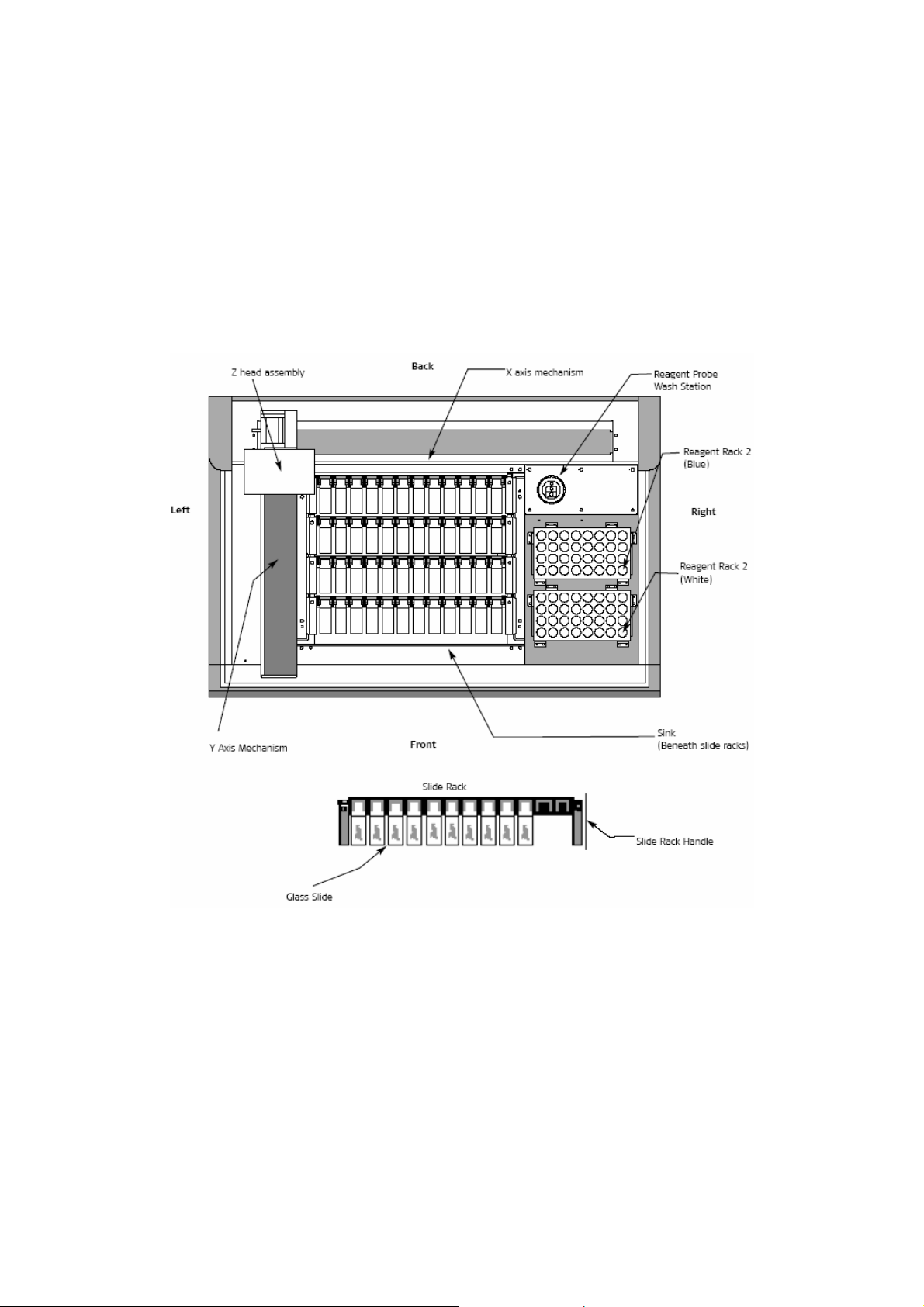
Slide Rack is a slide carrier holding 12 microscope slides in a horizontal
position. The instrument holds a maximum of 4 racks. These
racks are removable and interchangeable for slide loading and
unloading.
Glass Slide is a standard microscope slide to which specimen(s) is mounted
for processing on the instrument. Slide dimensions are 25 mm x
75 mm x 1 mm.
Reagent Racks
1 and 2
hold the reagent vials. There are 2 reagent racks: reagent rack
1 (white) sits in the front right side of the sink; reagent rack 2
(blue) sits behind reagent rack 1. The racks are identical in
shape and size. Each rack holds up to 32 reagent vials and is
marked with letters A-D and numbers 1-8 to designate each
reagent vial position. The computer always assigns reagents to
the front whit rack first. If additional reagents are required for a
procedure or for running the cleaning protocol the computer will
assign reagents to the blue rack.
Reagent Probe Wash
Station
is a white, plastic assembly located in the rear right corner of
the instrument and is used as a cleaning station for the
Teflon™-coated reagent probe. The probe is washed in the
wash station at the beginning of every run, prior to checking
reagent volumes, and application of each reagent.
Sink is the Teflon-coated tray that sits underneath the slide racks and
channels the buffer/DI water washes and reagents into the
waste reservoir.
Y Axis Mechanism is the robotic arm extending from the back of the instrument
towards the front carrying with it the Z head assembly. The Y
arm moves from right to left across the instrument. When the
Autostainer Plus is not in operation the Y arm rests on the left
side of the machine, When the instrument is in operation and
slides are incubating, the arm is located on the right side.
X Axis Mechanism enables the Y arm to move from left to right across the
instrument. The X axis is stationary across the back of the
instrument.
Z Head Assembly is the dome-shaped assembly that sits over the Y arm. The Z
head consists of three components: the probe tip; the wash
head and the blow head. These components move up and
down along the Z axis while the instrument is in operation. The
Z head moves back and forth along the Y axis mechanism,
allowing access to all slides and reagents.
12 Dako Autostainer Plus | User Guide
Page 13
Hardware Specifications
Dako Autostainer Plus
Dimensions 1.02m W x 0.69 m D x 0.61 m H 40” W x 27” D x 24” H
Weight 140 lb. (63.5 kg)
Electrical Requirements 120 V 110/120 V (±10%) 60 Hz (±2Hz)
220 V 220/240 V (±10%) 50 Hz (±2Hz)
Normal operating
temperature
Slide rack capacity 1 – 12 glass slides
Total slide capacity 1 – 48 glass slides
Reagent capacity 64 different reagents (15 Ml/reagent vial)
Reagent dispense volumes 100, 150, 200, 400 and 600 µL
Reagent probe volume
capacity
Computer Controller
These are the minimum
features provided. Dako
reserves the right to change
the computer controller
specifications at any time.
Monitor 14” color
Printer LaserJet or Inkjet Printer
Surge Protector 120 VAC, 15 Amps, 50/60 Hz
18º C-26º C (64º F-79º F)
100 µL minimum, 1200
NOTE: Computer specifications may vary.
Software Specifications
Operating System Windows® 98, XP or equivalent.
Operating Logic Designed to calculate the most time-efficient sequence to
complete a programmed staining run.
Protocol Logic Flexible selection of steps including rinses. Maximum of 35
protocol steps (including rinse steps)
Idle Rinse Buffer is applied to slides during a staining run to keep
specimens we when no reaction is occurring.
Rinse Default Settings Buffer rinse every 30 minutes prior to the start of a run, when
delayed start is selected. Buffer rinse every 30 minutes during a
staining run. Water rinse every 60 minutes after completion of
run. Default setting for time and the amount of buffer dispensed
can be changed by a Dako representative upon request.
Incubation Time Minimum time is 2 minutes.
Dako Autostainer Plus | User Guide 13
Page 14

Accessories included with the Dako Autostainer Plus
Slide Racks 4 non-disposable slide racks with a 12-slide capacity/rack. The
slide racks are suitable for standard glass slides; they are
removable and interchangeable
Reagent Racks 2 removable reagent racks. Each reagent rack holds a maximum
of 32 reagent vials.
Reagent Vials 100 reagent vials and caps. Each vial holds a maximum of 15
mL of reagent.
Buffer Container 1 ten-liter plastic container.
Deionized Water Container 1 ten-liter plastic container (not available with the “01” hardware
version of the Dako Autostainer Plus).
Waste Containers 2 ten-liter plastic containers.
User Guide 1 User Guide with detailed operating instructions.
Seymour Glass Label
Printer
The Seymour slide labeling system is a simple, efficient label
printing system for histology, cytology and research laboratories.
This system allows you to print only the labels you need – when
you them – for samples, microscope slides, reagent vials and
other items.
14 Dako Autostainer Plus | User Guide
Page 15
Section 3 | Installation Requirements
For installation of the Dako Autostainer Plus, the following requirements should be met to ensure that
the instrument functions properly.
Requirements
Surface
Size Minimum dimensions for the Dako Autostainer Plus work area
Environment The work area must also be an environment with an ambient
Buffer Container 1 ten-liter plastic container.
Deionized Water Container 1 ten-liter plastic container (not available with the “01” hardware
Waste Containers 2 ten-liter plastic containers.
User Guide 1 User Guide with detailed operating instructions.
Seymour Glass Label
Printer
Recommendations
Power source
Prior to unpacking the Dako Autostainer Plus, ensure that the
area to be used for instrument is a solid, level surface that can
safely support the weight of the system (approximately 240 lbs.
for instrument plus computer).
are
2.00 m wide x 0.8 m deep x 1.0 m height (78” w x 30” d x 37” h)
clearance.
temperature between 18° C-26° C (64° F-79° F), not facing
direct sunlight and not affected by a hood or vent.
version of the Dako Autostainer Plus).
The Seymour slide labeling system is a simple, efficient label
printing system for histology, cytology and research laboratories.
This system allows you to print only the labels you need – when
you them – for samples, microscope slides, reagent vials and
other items.
Dako recommends a dedicated power source for the Dako
Autostainer Plus to prevent interference from other instruments
or equipment.
Dako Autostainer Plus | User Guide 15
Page 16

This page is intentionally blank.
16 Dako Autostainer Plus | User Guide
Page 17

Section 4 | Typical Operation
A few “off instrument” preparations will make the staining run more time-efficient. Prior to starting a
run you should have the following items:
• A list of slide cases to be run with requested protocols.
• Deparaffinized and rehydrated slides soaking in buffer. This buffer should contain 0.05%
Tween 20. A minimum of 5 minutes soaking time is recommended.
• The reagents required for the staining run brought to room temperature.
• Sufficient buffer in the buffer reservoir and deionized water in the deionized water reservoir.
The buffer should contain 0.05% Tween 20 (deionized water is not available with the “01”
hardware version of the Dako Autostainer Plus).
• Containers for hazardous and non-hazardous waste with enough capacity to accommodate
the waste from the staining run.
A typical set up for a staining run follows this order:
6. Start the software by double clicking on the Dako Autostainer Plus icon.
7. Enter your user name and password (see Accessing the Dako Autostainer Plus Software,
Section 6).
8. Select the PROGRAM button on the MAIN MENU screen.
9. Select the SLIDE INFO button from the PROGRAMMING GRID, or Slides from the menu
bar. When the SLIDE INFO button is selected the SLIDE INFORMATION screen is
displayed. When the Slides menu item is selected the SLIDE COUNT window is
displayed.
10. Enter slide information or slide count for the staining run (see Entering Slide Information,
Section 8).
11. Select the FINISH ENTRY button when entering slide information or select OK when
using SLIDE COUNT window. The PROGRAMMING GRID is displayed with the slide
information.
12. Select the PROTOCOL TEMPLATE button. The PROTOCOL TEMPLATE DESIGN
screen is displayed.
13. Select the protocol template for the run (see Designing a Protocol, Section 9).
14. Select the USE TEMPLATE button. The PROGRAMMING GRID is displayed with the
selected protocol.
NOTE: Steps 7 through 9 can be skipped if the default template is used.
15. Assign specific reagents to all slides (see Programming Slides, Section 10).
16. Select the NEXT button. The user is prompted to “Save program on disk”.
Selecting YES displays the SAVE PROGRAM ON DISK window. Enter the program’s
name and select OK. The program is saved and the PRINT SLIDE LABELS screen is
displayed.
Selecting NO displays the PRINT SLIDE LABELS screen and the program is not saved.
17. Selecting the ALL button in the PRINT SLIDE LABELS screen will print all labels for slides
assigned in the PROGRAMMING GRID and bring the user to the REAGENT LAYOUT
MAP.
Dako Autostainer Plus | User Guide 17
Page 18

Selecting the UNPRINTED LABELS button will print all labels that were not printed
through the PRINT feature and bring the user to the REAGENT LAYOUT MAP.
Selecting the NONE button will direct the user to the REAGENT LAYOUT MAP.
The CANCEL button will return the user to the PROGRAMMING GRID.
18. Load reagents using the REAGENT LAYOUT MAP.
19. Select the NEXT button. The LOAD AND SCAN SLIDES screen appears.
20. If the Bar Code feature is disabled, load slides using the SLIDE LAYOUT MAP. If the Bar
Code feature is enabled, slides may be loaded into positions at the discretion of the user.
It is recommended that each slide be flooded gently with buffer after it is placed on the
instrument. This buffer should contain 0.05% Tween 20 (see Loading Slides, Section 13).
At no time should the slides dry out.
21. Select the SCAN SLIDES button to scan all slides on the instrument.
22. The IS THE ARM CLEAR TO MOVE? Screen is displayed. Select OK to proceed. If no
obstructions exist, select OK.
23. The SET START TIME screen is displayed (see Starting a Run, Section 14). The
Autostainer Plus calculates the run time and amount of buffer and DI water needed to
complete the run.
24. Select the PRIME PUMP (WATER) button. The DELAYED START dialog box appears
(deionized water is not available with the “01” hardware version of the Dako Autostainer
Plus). The user is prompted: “Is the pathway clear for the arm to move.”
25. Select the OK button and the pump is activated. Deionized water is flushed through the
water intake line.
26. Select the PRIME PUMP (BUFFER) button and the pump is activated, flushing buffer
through the buffer intake line. For the “01” hardware version of the Dako Autostainer Plus
the user is prompted: “Is the pathway clear for the arm to move.”
27. Set Reagent Levels to Check Volumes or Do Not Check Volumes (see Starting a Run,
Section 14).
28. Select the START RUN button and the run starts.
18 Dako Autostainer Plus | User Guide
Page 19
Section 5 | Programming Overview
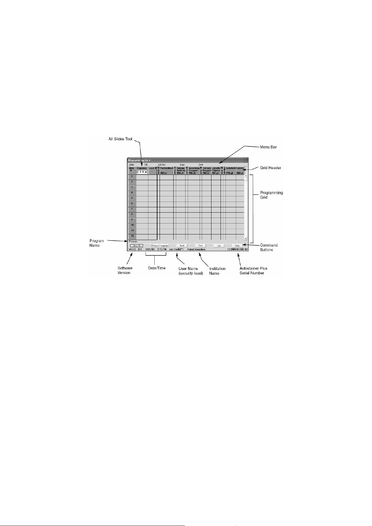
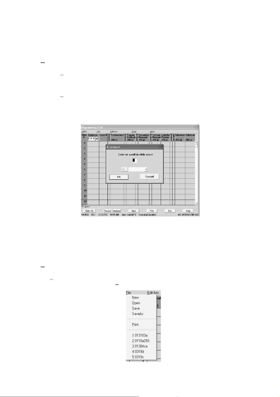
The Dako Autostainer Plus is a computer controlled system. The PROGRAMMING GRID is the main
screen used to define slide information, primary antibodies, staining reagents and staining protocols.
1. Five menus are accessible from the menu bar. The Slides menu item is used to enter the
number of slides to be run on the Autostainer Plus. The File menu is used for general
information such as opening, saving and printing previously saved runs. The Edit Lists
menu is used to establish lists of reagents utilized in programming a staining protocol.
The Copy and Auto menu items are used during programming.
2. The grid header lists the steps and dispense volumes of the selected protocol template
for the current staining run. Each column represents one step of the protocol template.
3. The programming grid is divided into rows and columns. Each row represents one slide
and displays the complete slide identification (e.g. Slide ID, Case #, Block DI, Doctor
Name, and Tissue) and all reagents applied. The grid will accommodate a maximum of 48
slides per staining run.
4. The 6 command buttons, located at the bottom of the screen, are used to enter slide
information, develop staining protocols (templates) and print reports.
5. Below the command buttons is a line of text that is displays the software version,
date/time, user name, security level, institution name, and Autostainer Plus serial number.
This information is edited from the INITIALIZE screen (see Initializing the Dako
Autostainer Plus, section 7). This line is on the bottom of most screens of the Autostainer
Plus software.
6. The ALL SLIDES tool enables the user to alter drop zones and reagent application
amounts for all slides in the program.
7. The INDIVIDUAL SLIDE tools enable the user to alter the drop zone and reagent
application amount for that particular slide.
Dako Autostainer Plus | User Guide 19
Page 20
Menu Bar Options
lides Function
S
The S
lides option may be used as an alternative to expedite programming by reducing the
amount of information required to program a staining run. The Slides option may be used to
enter the total number of slides for the current staining run.
The S
lides function can be accessed by moving the mouse pointer to Slides on the menu bar
and pressing the left mouse button. This selection displays the SLIDE COUNT window for
entering the number of slides for the current staining run. This function is used to bypass the
SLIDE INFORMATION screen when programming a staining run. Enter the desired number of
slides in the text box or use the scroll bar to select the desired number of slides.
Once a run has been set up using the SLIDE COUNT window, slide ID, case number, doctor,
block ID or tissue information cannot be added to the run. Selecting the SLIDE INFO button
displays the SLIDE COUNT window.
NOTE: Slide Identification, Case #, Block ID, Tissue or Doctor Name will not be
associated/displayed in the Programming Grid if the Slides function is used.
File Menu
The File menu can be accessed by moving the mouse pointer to File on the menu bar and
pressing the left mouse button. The F
ile menu commands include:
20 Dako Autostainer Plus | User Guide
Page 21
ew displays a blank grid to program a new staining run
N
Open displays the LOAD PROGRAM FROM DISK window
Save saves the current staining run program.
Save As saves an existing staining run program under a new
Print prints the current Program Grid, IHC Report, Slide
Note: The list at the bottom of the file menu displays the last
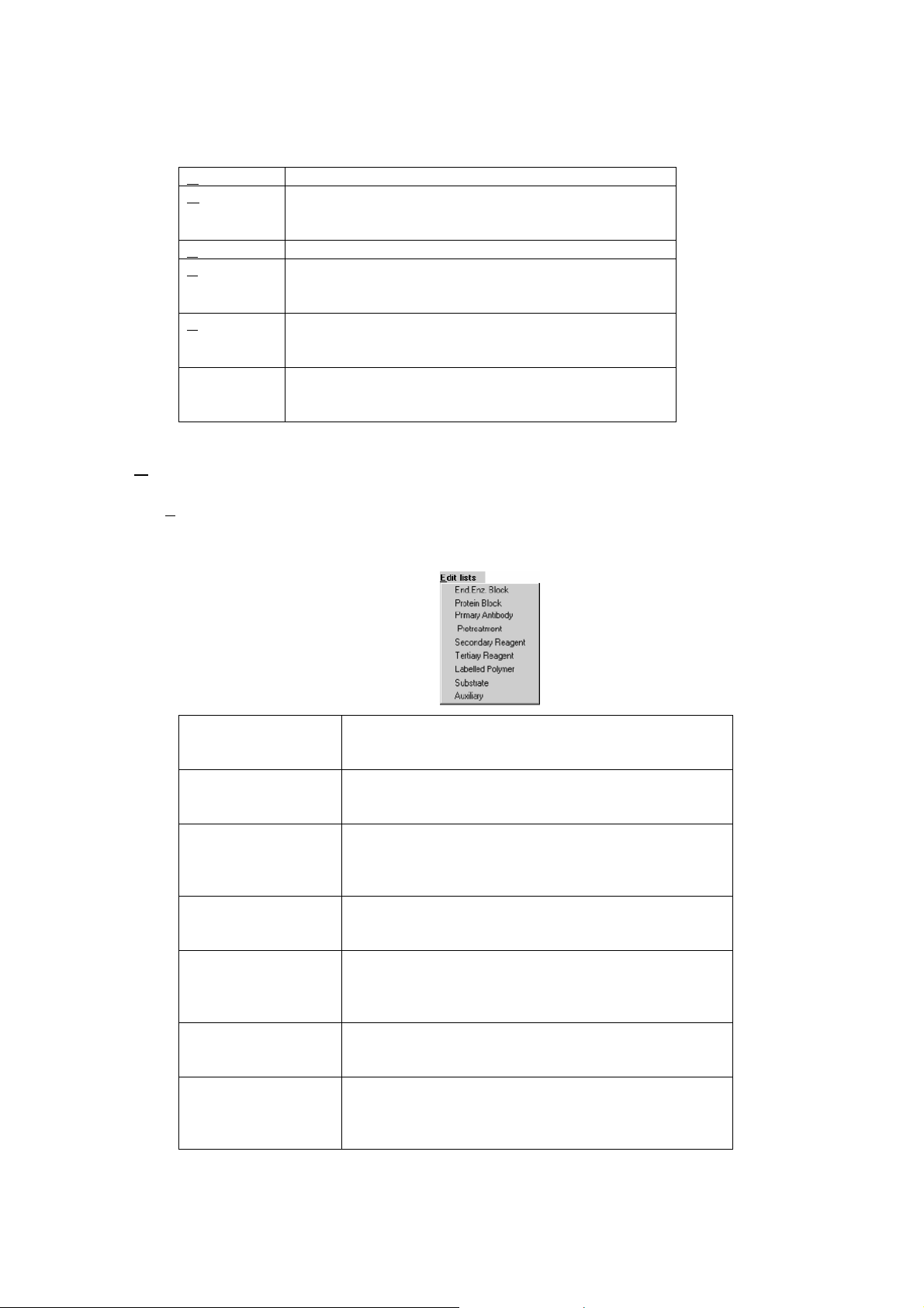
dit Lists Menu
E
The E
dit Lists menu can be accessed by moving the mouse pointer to Edit lists on the menu bar
and pressing the left mouse button. For instruction on the features of the Edit List menu item, see
Reagent Management, section 11. The Edit Lists menu commands include:
with a list of all saved staining runs available to be
opened.
name while the original program remains under its
saved name.
Labels, Reagent Labels, Reagent List, or any Run
Log.
five programs accessed in the computer. This list is
constantly updated.
End. Enz. Block displays the EDIT REAGENT LIST screen for
endogenous enzyme block, allowing programming
and editing of endogenous enzyme block reagents.
Protein Block displays the EDIT REAGENT LIST screen for protein
block, allowing programming and editing of protein
block reagents.
Primary Antibody displays the EDIT REAGENT LIST screen for primary
antibodies, allowing programming and editing of
primary antibody reagents. The PRETREATMENT list
is also accessible from this screen.
Pretreatment displays the EDIT REAGENT LIST screen for primary
antibody pretreatment, allowing programming and
editing of pretreatment reagents.
Secondary Reagent displays the EDIT REAGENT LIST screen for
secondary reagents (e.g. biotinylated secondary
antibodies or link), allowing programming and editing
of secondary reagents.
Tertiary Reagent displays the EDIT REAGENT LIST screen for tertiary
reagents (e.g. enzyme-labeled streptavidin or label),
allowing programming and editing of tertiary reagents.
Labeled Polymer displays the EDIT REAGENT LIST screen for labeled
polymer reagents used in the Dako EnVision
visualization systems, allowing programming and
editing of labeled polymer reagents.
Dako Autostainer Plus | User Guide 21
Page 22
Substrate displays the EDIT REAGENT LIST screen for
Auxiliary displays the EDIT REAGENT LIST screen for auxiliary
substrates, allowing programming and editing of
substrate reagents.
reagents (e.g. counterstain), allowing programming
and editing of auxiliary reagents.
Copy Function
The Copy function can be accessed by moving the mouse pointer to Copy on the menu bar and
pressing the left mouse button. This function activates the Select and Paste commands which
allow selection of programmed tiles in the Programming Grid. The selected tiles can be copied
over (pasted) on either unprogrammed or programmed tiles (see the Copy section of Programming
Slides, section 10).
Auto Function
The Auto function can be accessed by moving the mouse pointer to Auto on the menu bar and
pressing the left mouse button. This function is used to save all or any portion of a protocol to be
used in other programs (see the Auto Programming section of Programming Slides, section 10).
The Help function is also accessible from this menu.
Command Buttons
The command buttons on the PROGRAMMING GRID and their respective functions are:
Slide Info displays the SLIDE INFORMATION screen to enter
new or edit existing slide information (e.g. Slide ID,
Case #, Block ID, # Slides, Tissue and Doctor Name).
Protocol Template displays the PROTOCOL TEMPLATE DESIGN screen
where a saved protocol template can be retrieved or a
new one created. This template is applied to the
current staining run
Next displays the PRINT SLIDE LABELS screen
Print prints the Slide Labels, Reagent Labels, Main Grid,
IHC Report, Reagent List, or Run Logs.
Exit returns to the MAIN MENU screen without saving the
program.
Help displays information to aid in the understanding and
utilization of features in the PROGRAMMING GRID.
22 Dako Autostainer Plus | User Guide
Page 23
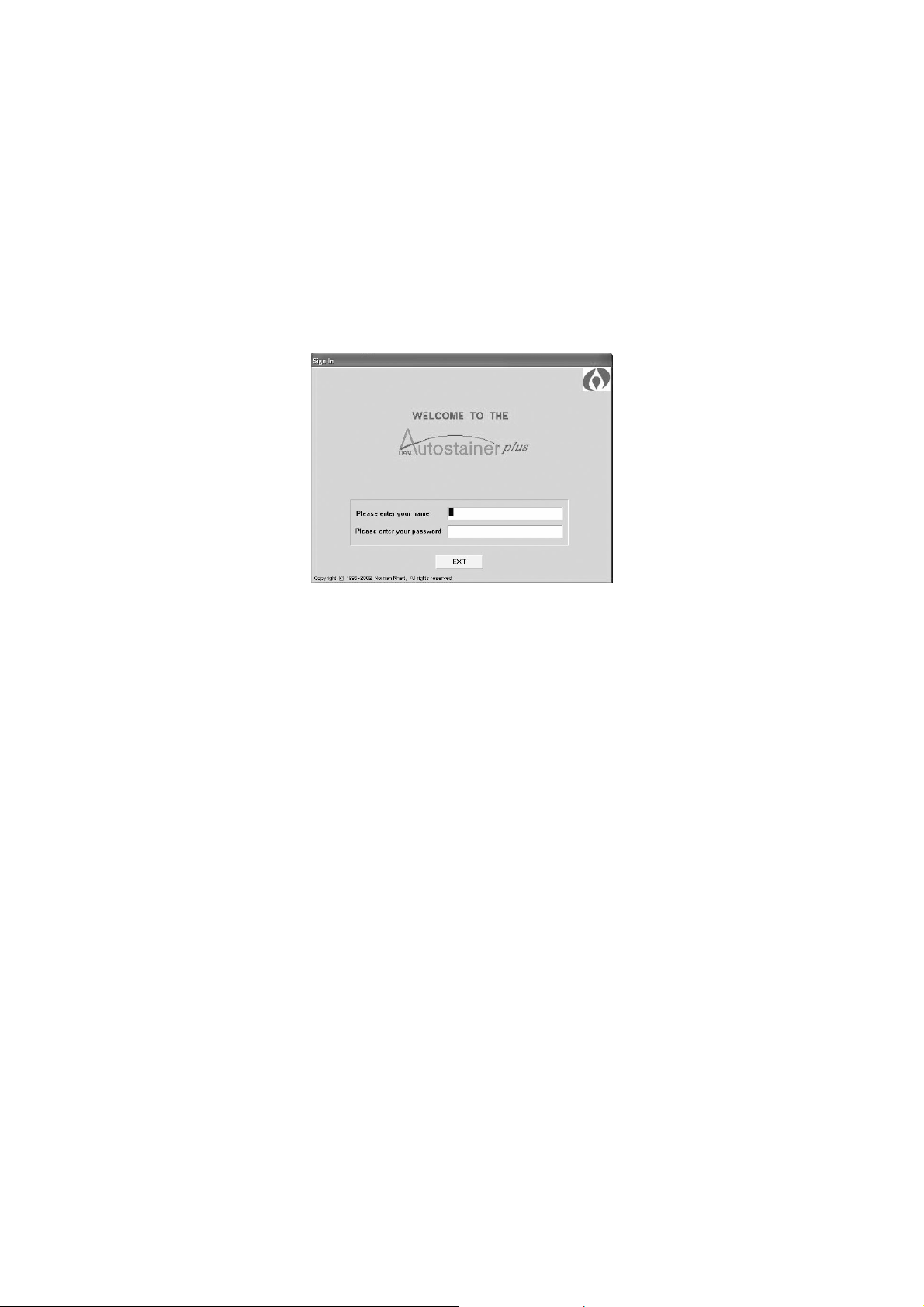
Section 6 | Accessing the Dako Autostainer Plus
Software
The SIGN IN screen is the first screen that appears after the Dako Autostainer Plus icon is double
clicked.
The SIGN IN screen allows you to enter your assigned user name (up to 28 alpha-numeric
characters) and password (up to 8 alpha-numeric characters). Your user security status (programmed
in the INITIALIZE screen) determines the functions you are able to access. If the sign-in process is
executed correctly (i.e., valid user name and password entered), the system displays the MAIN MENU
screen.
To add a new user or change a password of an existing user, see Initializing the Dako Autostainer
Plus, Section 7.
1. The cursor is located in the name box. Type your name and press the ENTER key. The
cursor moves to the password box.
2. Type your password and press ENTER. Only asterisks (*) will be displayed in the entry
box during keystroke entry. The MAIN MENU screen is displayed.
If an unrecognizable name and/or password is entered, the software does not allow you to continue to
the next entry. For example, if an unrecognized name is entered and the ENTER key is pressed the
cursor remains in the name box and does not move to the password box.
If EXIT is selected a dialog box prompts, “Quit using Autostainer Plus?”. Select YES to return to the
main Windows screen. Select NO to return to the SIGN IN screen.
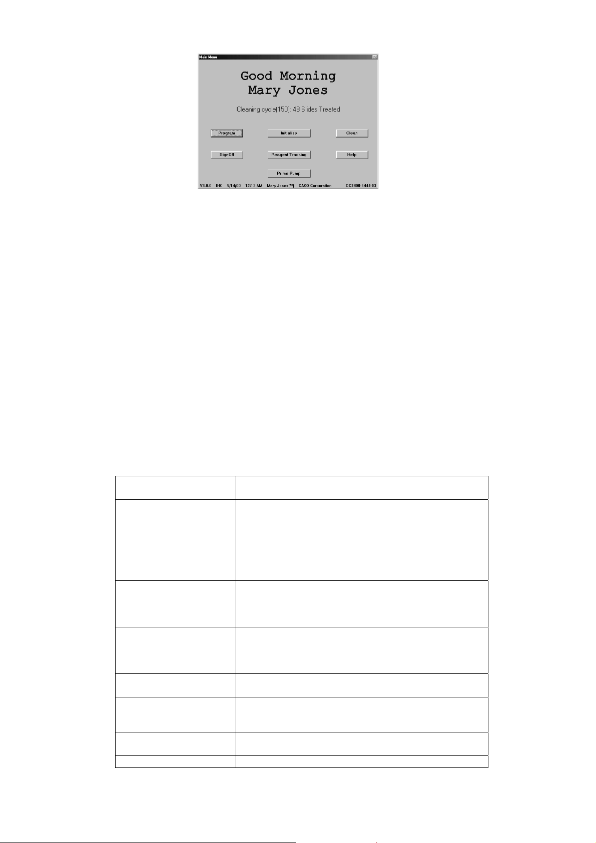
The MAIN MENU screen appears when the sign-in process is properly executed. This screen allows
high security level users access to all the software features. The INITIALIZE button is displayed for
only high security level users. A user’s security status is entered from the INITIALIZE screen (see
Initializing the Dako Autostainer Plus, section 7).
Dako Autostainer Plus | User Guide 23
Page 24
If the accessing operator is assigned a middle or low security level, the INITIALIZE button is replaced
with the CHANGE PASSWORD button. A middle or low security level does not allow access to set or
change the parameters for slide labels, Main Grid and IHC Report printing formats, cleaning schedule
or signing on new users and doctors.
NOTE: In the example above, the INITIALIZE button is displayed, indicating this user is set at high
security level.
NOTE: The software version number, current date and time, user name, security level (indicated by
asterisks), institution name, and Autostainer Plus serial number are displayed across the bottom of
this screen.
NOTE: A cleaning run is recommended after 150 slides have been processed on the Autostainer
Plus. Once the cleaning cycle is set up (see System Maintenance, section 17) this number and the
number of slides processed since the last cleaning appear in red letters. Once the instrument has
processed 150 slides, a message will prompt the user to clean the instrument.
The software allows up to 200 slides to be run between cleaning cycles. The additional 50 slides
allows for flexibility in the laboratory work flow to perform an additional run before cleaning the
instrument. If more than 200 slides have been run the instrument must be cleaned. The PROGRAM
button becomes unavailable and the software does not allow additional programming until the
instrument has gone through a cleaning cycle.
PROGRAM is used during routine operation of the Autostainer
Plus and allow access to the PROGRAMMING GRID
INITIALIZE displays the INITIZLIZE screen used to establish and
update default information for institution, staff, the
number of slides per routine cleaning cycle, the
default reagent volume and drop zone for reagent
dispense. You may also name your system or identify
your system by serial number on this screen. This
button is only displayed for high security level users.
CHANGE PASSWORD displays the CHANGE PASSWORD screen used to
edit the signed on user’s password. This button
replaces the INITIALIZE button for users with middle
and low security access.
CLEAN allows you to initiate a cleaning run. It gives a status
report on the number of slides since the last cleaning
cycle and the total number of runs and generates a
Cleaning Log.
REAGENT TRACKING allows users to monitor the total volume of each
reagent that has been used on the Autostainer Plus.
PRIME PUMP displays the PRIME PUMP screen used to flush the
intake tubing with buffer or DI water without initiating
an actual run.
HELP displays information to aid in understanding and
utilizing the features on the MAIN MENU screen.
SIGN OFF exits the Autostainer Plus program.
24 Dako Autostainer Plus | User Guide
Page 25
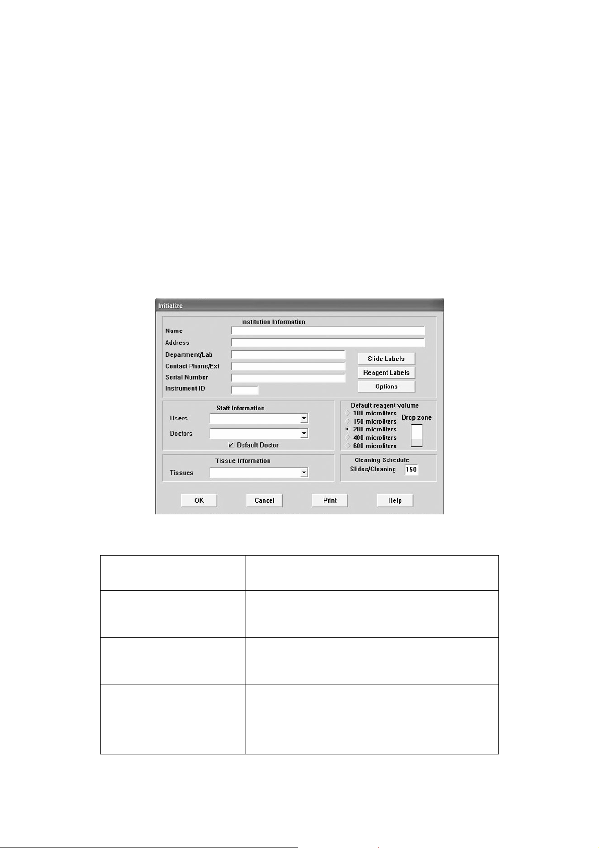
Section 7 | Initializing the Dako Autostainer Plus
The INITIALIZE screen is used to establish and update default information for the system. This
includes the institution information, Autostainer Plus serial number, user names, the doctors
requesting IHC tests, a library of tissues that may be used during staining, the number of slides
allowed between routine cleaning runs, the default volume and the drop zone for reagent dispense.
Slide and reagent label formatting, and user-defined printing formats for the Main Grid and IHC
Reports, and custom options can also be configured from this screen.
This screen is used to enter information for: Institution, Autostainer Plus serial number, instrument ID,
staff, default reagent volume and drop zone, slides per cleaning cycle, and to access the Slide and
Reagent Design Label and Options screens.
The buttons on the INITIALIZE screen and their respective functions are:
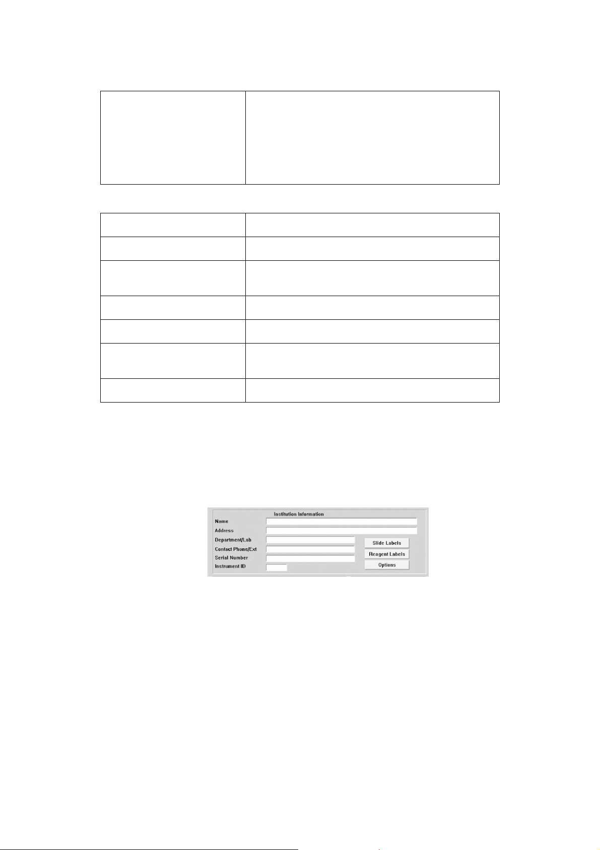
Institution Information The Institution Information (name, address,
department, phone, serial number) is stored and
incorporated into reports
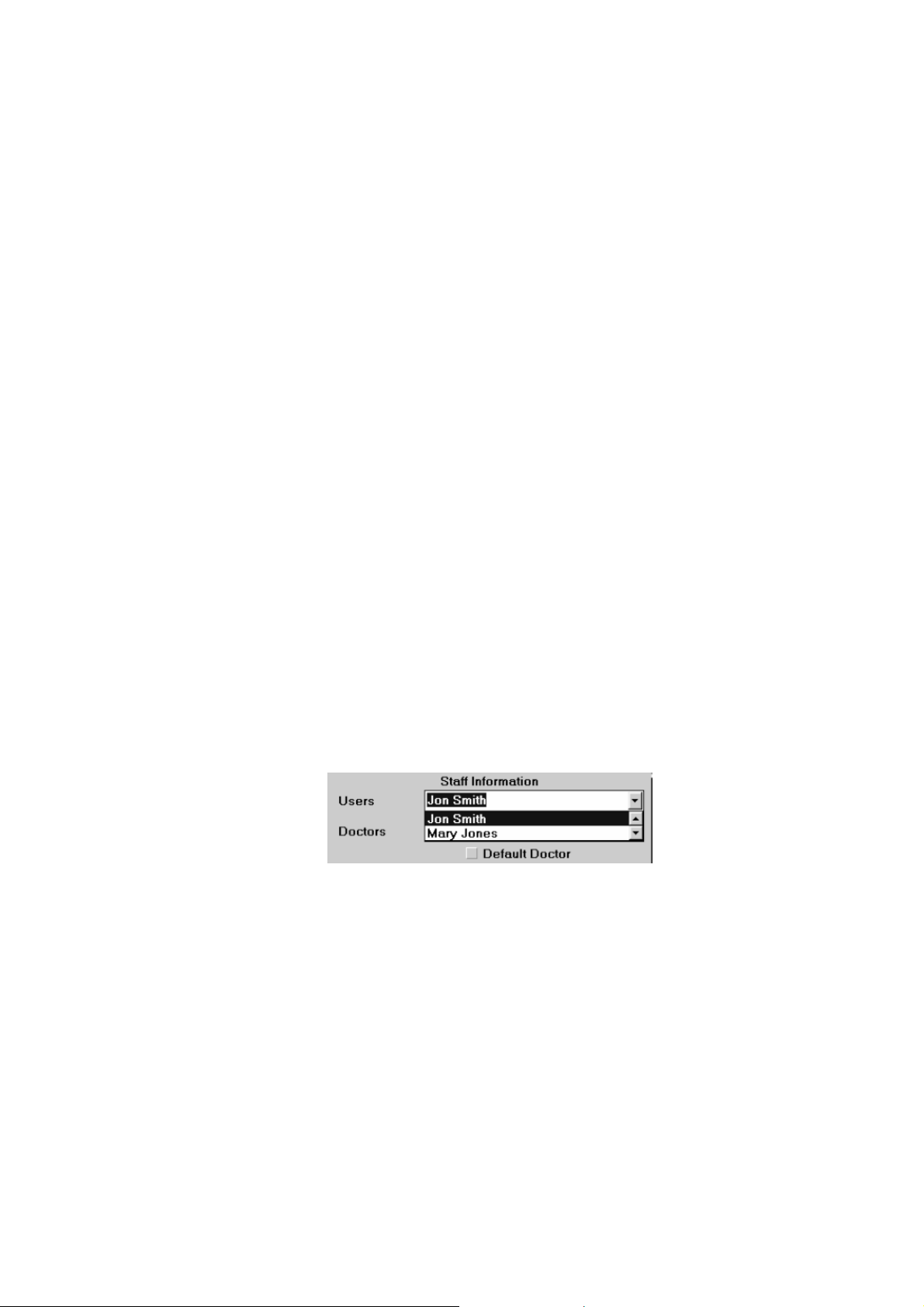
Staff Information The Staff Information includes lists of the Users and
Doctors who frequently request IHC tests. The list of
Doctors is accessed during the programming of the
slide information
Tissue Information The Tissue Information list is used to save a list of
tissues that are frequently used IHC tests. This list of
tissues is accessed during the programming of slide
information.
Default Reagent Information The Default Reagent Volume allows the selection of
the default reagent volume to be used for all steps in
any staining protocol. Reagent volume choices are:
100, 150, 200, 400, and 600 µL. The Default Reagent
Drop Zone is also selected, allowing application of
reagent to single or multiple locations on each slide.
Dako Autostainer Plus | User Guide 25
Page 26
The buttons on the INITIALIZE screen and their respective functions are:
Cleaning Schedule The Slides/Cleaning permits you to program the
number of slides stained between routine cleanings.
Dako recommends a cleaning cycle after every 150
slides. Once the programmed number is exceeded,
the MAIN MENU screen displays the number of slides
since the last cleaning. The maximum slides allowed
between cleaning cycles is 200. Once this number is
exceeded, the PROGRAM button is not available.
SLIDE LABELS displays the DESIGN SLIDE LABEL screen used to
define slide label printing of bar-coded slide labels.
REAGENT LABELS displays the DESIGN REAGENT LABEL screen used
to define the printing of reagent labels.
OPTIONS displays the OPTION screen used to define the format
for the Program Grid, Slide Layout Map, and printing
format for IHC Reports.
OK saves the entered information and returns to the MAIN
MENU screen.
CANCEL cancels any entries made and returns to the MAIN
MENU screen.
PRINT prints a report listing all of the institution, staff, tissue,
default volume, default dispense zones, and cleaning
schedule information.
HELP displays information to aid in understanding and
utilizing the INITIALIZE screen.
Entering Institution Information
1. Select INITIALIZE on the MAIN MENU screen. The INITIALIZE screen is displayed with
the cursor in the Name box.
2. Type in the institution’s name and press ENTER or TAB. The cursor moves to the
Address box.
NOTE: Information entry is limited to the space displayed on the screen. When the end
of an entry box is reached, an audible tone is made by the computer and no additional
information can be added in that box.
3. Type in the institution’s address and press ENTER or TAB. The cursor moves to the
Department/Lab box.
4. Type in the laboratory or department where the Dako Autostainer Plus will be operating
and press ENTER or TAB. The cursor moves to the Contact Phone/Ext. box.
5. Type in the laboratory’s phone number and press ENTER or TAB. The cursor moves to
the Serial Number box.
6. Type in the Autostainer Plus serial number located on the right side of the instrument.
The number should start with “S38-“ and followed by 6 additional numbers. Press
ENTER or TAB. The cursor moves to the Users box.
NOTE: Once entered, the instrument serial number will be located in the lower right
corner of many of the screens in the Autostainer Plus software.
26 Dako Autostainer Plus | User Guide
Page 27
7. Type in serial number, name, or unique identifier, for your Autostainer Plus and press
ENTER or TAB.
8. Select the OK button to save the entered information. The MAIN MENU screen is
displayed.
Select the CANCEL button to escape without saving the entered information. The MAIN
MENU screen is displayed.
Editing Institution Information
1. Select INITIALIZE on the MAIN MENU screen. The INITIALIZE screen is displayed with
the cursor in the Name box and the previously entered information listed.
2. Select the information to be changed and enter the new information.
3. Select the OK button to save the entered information. The MAIN MENU screen is
displayed. Select the CANCEL button to escape without saving the changes. The MAIN
MENU screen is displayed.
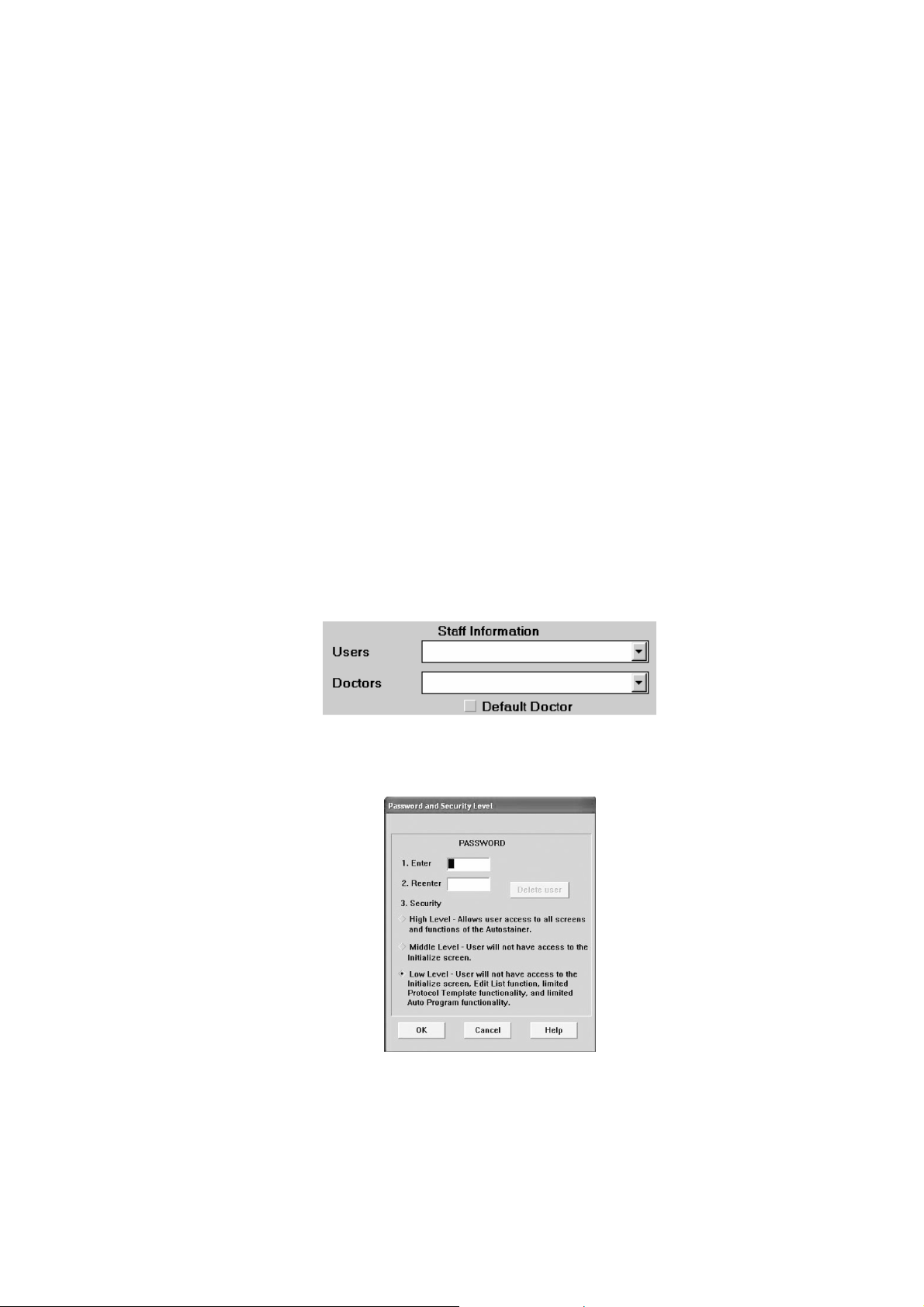
Entering Staff Information
Adding a New User
1. Select INITIALIZE on the MAIN MENU screen. The INITIALIZE screen is displayed with
the cursor in the Name box and the previously entered information is listed.
2. Press ENTER or TAB key until the cursor flashes in the Users box.
3. Type a user’s name and press ENTER. The PASSWORD AND SECURITY LEVEL
screen appears.
4. Type in a password for the new user in the Enter box and press ENTER. The cursor
moves to the Reenter box.
NOTE: Passwords are not case sensitive; capital and lower case letters may be
interchanged.
Dako Autostainer Plus | User Guide 27
Page 28
5. Type in the same password again and press ENTER. The High security level option
becomes highlighted. If a different password is entered the window “TRY AGAIN:
Password must be identical” appears.
6. Using the mouse, select the desired security level. A mark appears in the raised
diamond. Selecting the High Level option allows full access to the software features.
Select OK and the INITIALIZE screen appears.
NOTE: Each security level is displayed at the bottom of each screen with asterisks in
parenthesis “()”. (See below for details).
The security levels are defined as follows:
High Level (**): Users have full access to all features of the software.
Middle Level (*): Users do not have access to the INITIALIZE button in the MAIN MENU screen. This
button is replaced with a CHANGE PASSWORD button. Middle level users cannot set or change the
parameters for Institution info, default slide settings, slide/reagent labels, Main Grid and IHC printing
formats, cleaning schedule, entering in new users and doctors, or adding new tissues.
Low Level: Users do not have access to the INITIALIZE button in the MAIN MENU screen. This
button is replaced with a CHANGE PASSWORD button. Users with low level security are also
restricted from the same features as users with middle level security and the following: no access to
Reagent Tracking, the Edit List function, setting up Auto Program, creating/editing Protocol
Templates.
7. Select the OK button to save the entered information. The new user name and password
is added to the current list of users and MAIN MENU screen appears.
Select the CANCEL button to escape without saving the entered information. The MAIN
MENU screen appears.
Editing User Information
1. Select INITIALIZE on the MAIN MENU screen. The INITIALIZE screen is displayed with
the cursor in the Name box and the previously entered information listed.
2. Press ENTER or TAB key until the cursor flashes in the Technologists box.
3. Select the user name from the list and press ENTER. The PASSWORD AND SECURITY
LEVEL screen appears.
NOTE: The Users list can be displayed by positioning and clicking the mouse pointer in
the Users box and pressing the DOWN arrow key on your keyboard until the desired
user’s name is highlighted in the Users box. The scroll arrows in the drop down list can
also be used.
4. The Password boxes are empty. Enter the new password information.
5. To change a user’s security status, move the mouse pointer over the desired security
level and press the left mouse button. A mark will appear next the selected security level.
Select the OK button to save the changes.
Selecting the CANCEL button displays the INITIALIZE screen without saving the newly
entered information.
28 Dako Autostainer Plus | User Guide
Page 29
Deleting User Information
1. Select INITIALIZE on the MAIN MENU screen. The INITIALIZE screen is displayed with
the cursor in the Name box and the previously entered information listed.
2. Press ENTER or TAB key until the cursor flashes in the Users box.
3. Select the user name from the list and press ENTER. The PASSWORD AND SECURITY
LEVEL screen appears. The DELETE USER button located to the right of the entry boxes
becomes available.
4. Select the DELETE USER button. A dialog box asking if you want to delete the selected
user (by name) appears.
5. Select the YES button to delete the user from the current list of users and the INITIALIZE
screen appears.
Select the NO button and the PASSWORDS AND SECURITY LEVEL screen is displayed
without deleting the selected user. Select CANCEL to return to the INITIALIZE screen.
NOTE: A user cannot be deleted from the current user list if his/her name was used to
sign in for the current session. The DELETE USER button is grayed out and not available.
Adding a New Doctor
1. Select INITIALIZE on the MAIN MENU screen. The INITIALIZE screen is displayed with
the cursor in the Name box and the previously entered information listed.
2. Press ENTER or TAB key until the cursor flashes in the Doctors box.
3. Type in the Doctors name and press ENTER. A dialog box appears asking if you want to
add the current doctor to the list.
4. Select the YES button. The INITIALIZE screen appears and the newly entered doctor’s
name is added to the list.
Select the NO button. The INITIALIZE screen is displayed and the information is not
saved.
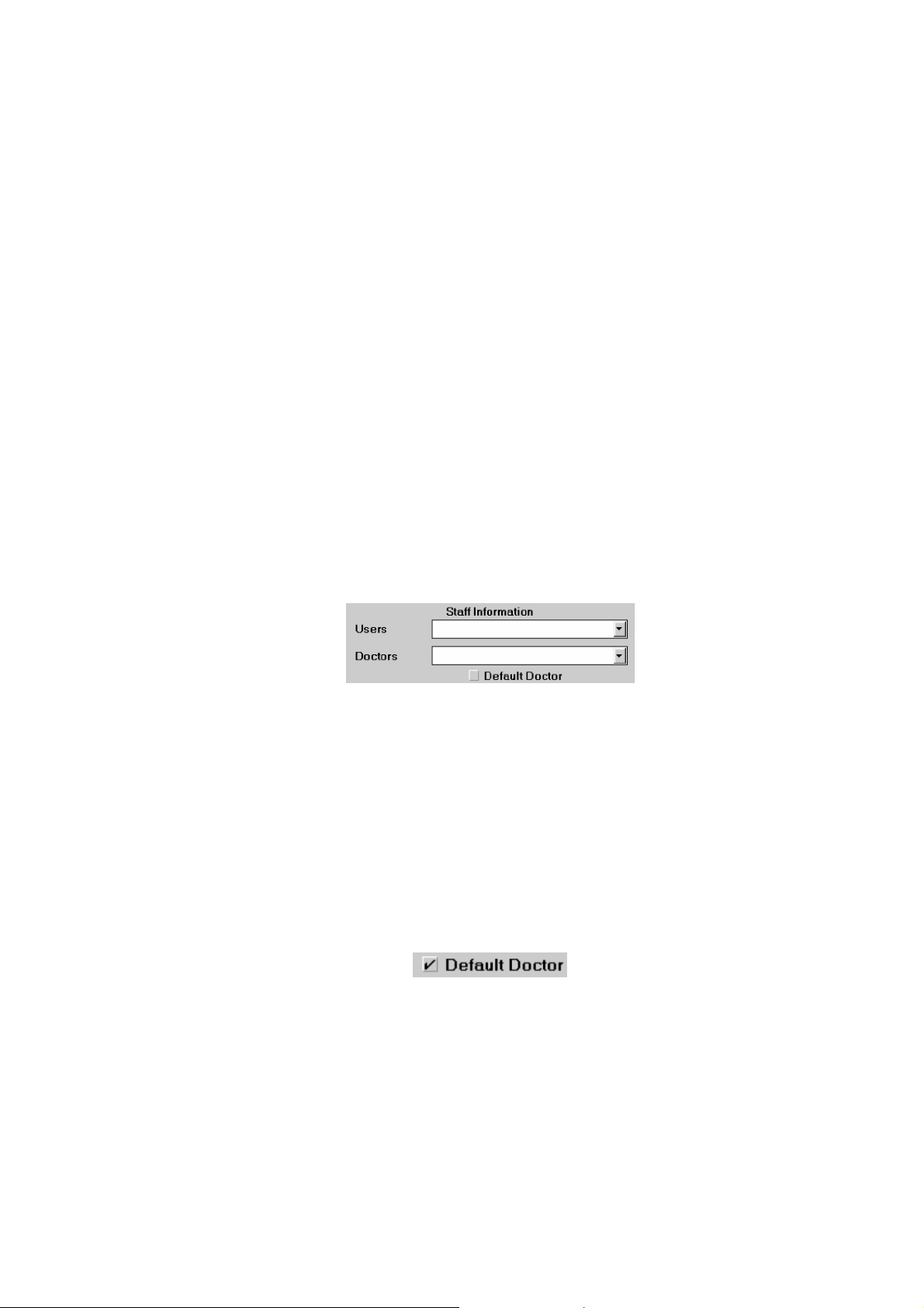
5. To set the displayed doctor as the Default Doctor, move the mouse pointer over the
Default Doctor check box and press the left mouse button. A check mark is placed in the
box and the doctor’s name is displayed in the SLIDE INFORMATION screen as the
default doctor. This name also appears in the Doctor column in the PROGRAMMING
GRID.
To change the Default Doctor, select the name of the new default and select the Default
Doctor check box. A check is placed in the box. The initial doctor is no longer set as the
default.
NOTE: To edit a doctor’s name, first delete the name, then enter the new information.
Dako Autostainer Plus | User Guide 29
Page 30

Deleting Doctor Information
1. Select INITIALIZE on the MAIN MENU screen. The INITIALIZE screen is displayed with
the cursor in the Name box and the previously entered information listed.
2. Press ENTER or TAB key until the cursor flashes in the Doctors box.
3. Select a doctor from the current list of doctors.
4. Press ENTER. A dialog box appears asking if you want to delete the selected doctor.
5. Select the YES button. The selected doctor is deleted from the current list and the
INITIALIZE screen appears.
Select the NO button and the INITIALIZE screen is displayed and the highlighted doctor is
not removed from the list.
Entering Tissue Information
Adding a New Tissue
1. Select INITIALIZE on the MAIN MENU screen. The INITIALIZE screen is displayed with
the cursor in the Name box and the previously entered information listed.
2. Press ENTER or TAB key until the cursor flashes in the Tissue box.
3. Type in the tissue and press ENTER. A dialog box appears asking if you want to add the
current tissue to the list.
4. Select the YES button. The INITIALIZE screen appears and the newly entered tissue is
added to the list.
Select the NO button. The INITIALIZE screen is displayed and the information is not
saved.
NOTE: To edit a tissue, first delete the tissue, then enter the new information.
Deleting a Tissue
1. Select INITIALIZE on the MAIN MENU screen. The INITIALIZE screen is displayed with
the cursor in the Name box and the previously entered information listed.
2. Press ENTER or TAB key until the cursor flashes in the Tissue box.
3. Select a tissue from the current list of tissues.
4. Press ENTER. A dialog box appears asking if you want to delete the selected tissue.
5. Select the YES button. The selected tissue is deleted from the current list and the
INITIALIZE screen appears.
Select the NO button and the INITIALIZE screen is displayed and the highlighted tissue is
not removed from the list.
Entering Default Reagent Information
Assigning Default Reagent Dispense Volumes
1. Select INITIALIZE on the MAIN MENU screen. The INITIALIZE screen is displayed.
2. Select a default reagent volume by clicking on a raised diamond next to the appropriate
volume. A smaller black diamond appears next to the selected volume.
3. Select the OK button to save. The MAIN MENU screen is displayed.
30 Dako Autostainer Plus | User Guide
Page 31

Select the CANCEL button to escape without saving. The MAIN MENU screen is
displayed.
NOTE: The dispense volume selected on this screen is the default volume assigned to
all reagents in any programmed staining run. The volume for all reagents as well as for
specific reagents applied to all slides in a particular staining run can be changed in the
PROTOCOL TEMPLATE DESIGN screen. In addition, the dispense volume can also be
changed on an individual slide in the PROGRAM SLIDES screen (see Programming
Slides, Section 10).
4. To change the Default Reagent Dispense volume, click on the raised diamond next to the
new volume. A smaller black diamond appears next to the selected volume.
Assigning Reagent Drop Zone
The area(s) on the microscope slide where the reagent is dispensed is defined as the Drop
Zone(s). The default drop zone information is used when a new Protocol Template is created.
1. Move the mouse pointer over the top, middle or bottom portion of the microscope slide
image and press the left mouse button. A yellow bar appears on the slide in the selected
position. During the staining run, the selected Default Reagent Volume is dispensed on
this zone of the slides for all steps of the protocol.
2. Multiple drop zones can be selected by clicking on multiple (2 or 3) areas while holding
down the CONTROL (CTRL) key on the keyboard. Multiple zones are colored yellow.
During the staining run the selected Default Reagent Volume is dispensed on each of the
selected zones.
3. Select the OK button to save and the MAIN MENU screen is displayed.
Select the CANCEL button to escape without changing the Drop Zone. The MAIN MENU
screen is displayed.
NOTE: The drop zones(s) are selected to correspond to the location of tissues on the
slide.
Cleaning Schedule
This selection determines the number of slides the instrument will stain prior to prompting the
user to start a cleaning cycle. Dako recommends setting the cleaning schedule to 150 slides. The
MAIN MENU screen always displays the total number of slides processed since the last cleaning
cycle in red.
1. Move and click the mouse pointer on the Slides/Cleaning box and type in the number of
slides to stain between maintenance cleanings. Select the OK button and the MAIN
MENU screen is displayed.
Dako Autostainer Plus | User Guide 31
Page 32

Select the CANCEL button to escape without saving. The MAIN MENU screen is
displayed.
NOTE: This number can be changed by highlighting the entered number and typing the
new number of slides. Select the OK button and the MAIN MENU screen is displayed.
NOTE: The maximum number of slides allowed per cleaning cycle is 200 slides. If a
number greater than 200 is placed in this field, then you will be prompted to reduce your
slide number to 200 or less. Once more than 200 slides have been run on the Autostainer
Plus, the PROGRAM button will not be available.
Label Printing Initialization
Slide Labels
The SLIDE LABELS button is displayed on the INITIALIZE screen and it is used to access the
DESIGN SLIDE LABEL screen for configuring and adjusting slide label printing.
Slide Labels with Bar Codes
The Autostainer Plus adds a Bar Code identification to each slide label. The identification is
assigned under the Instrument ID portion of the INITIALIZE screen.
NOTE: Slide labels are printed from the print button on the PROGRAMMING GRID or the PRINT
SLIDE LABELS screen accessed by the NEXT button in the PROGRAMMING GRID. Do not print
labels while the Autostainer Plus is operating.
1. Select the SLIDE LABELS button. The DESIGN SLIDE LABEL screen appears with three
fields displayed representing the three lines of information to be printed on each slide
label.
NOTE: Each field offers 10 options: Slide ID, Case #, User, Primary 1, Primary 2,
Pretreatment, Today’s Date, Run Name, Doctor and Tissue. The information printed for
each field is the data entered in the SLIDE INFORMATION screen and appearance of the
Programming Grid.
NOTE: If Slide ID, Doctor or Tissue is selected to print on the label, then these items
must be selected from the OPTIONS button in the INITIALIZE screen. If these Program
Grid items are not selected from the OPTIONS button in the INITIALIZE screen, then
these fields will not be present in the SLIDE INFORMATION screen.
2. Move the mouse pointer over the down arrow to the right of the information box and press
the left mouse button. A list box with the 10 options is displayed.
32 Dako Autostainer Plus | User Guide
Page 33

3. Select the desired option for the field. The list box disappears and the selected option is
displayed in the field.
NOTE: Static information can be entered into the field. This information is printed on
every label. For example, the institution name can be printed on every label. To enter
static information, highlight the text in the desired field and type the text in the text box.
Press ENTER.
4. Select the number of characters for each line (10, 12, 14, or 16) by selecting a number
from the LENGTH list (Selecting 10 characters will display bold text).
NOTE: The greater the number of characters, the smaller the text will appear on the
labels.
If you do not wish to use the Bar Code feature for slide labels, go to the CUSTOM
OPTIONS area of the OPTIONS menu on the INITIALIZE screen, and select “Disable Bar
Code.”
Slide Labels without Bar Code
If you have selected the “Disable Bar Code” option, the Autostainer Plus will provide labels in the
same way as the earlier Autostainer, as follows.
NOTE: Slide labels are printed from the print button on the PROGRAMMING GRID or the PRINT
SLIDE LABELS screen accessed by the NEXT button in the PROGRAMMING GRID. Do not print
labels while the Autostainer Plus is operating.
1. Select the SLIDE LABELS button. The DESIGN SLIDE LABEL screen appears with six
fields displayed representing the six lines of information to be printed on each slide label.
NOTE: Each field offers 10 options: Slide ID, Case #, User, Primary 1, Primary 2,
Pretreatment, Today’s Date, Run Name, Doctor and Tissue. The information printed for
each field is the data entered in the SLIDE INFORMATION screen and appearance of the
Programming Grid.
NOTE: If Slide ID, Doctor or Tissue is selected to print on the label, then these items
must be selected from the OPTIONS button in the INITIALIZE screen. If these Program
Grid items are not selected from the OPTIONS button in the INITIALIZE screen, then
these fields will not be present in the SLIDE INFORMATION screen.
2. Move the mouse pointer over the down arrow to the right of the information box and press
the left mouse button. A list box with the 10 options is displayed.
3. Select the desired option for the field. The list box disappears and the selected option is
displayed in the field.
NOTE: Static information can be entered into the field. This information is printed on
every label. For example, the institution name can be printed on every label. To enter
Dako Autostainer Plus | User Guide 33
Page 34

static information, highlight the text in the desired field and type the text in the text box.
Press ENTER.
4. Select the number of characters for each line (10, 12, 14, or 16) by selecting a number
from the LENGTH list (selecting 10 characters will display bold text).
NOTE: The greater the number of characters, the smaller the text will appear on the
labels.
Reagent Labels
The REAGENT LABELS button is displayed on the INITIALIZE screen and it is used to access the
DESIGN REAGENT LABEL screen for configuring and adjusting reagent label printing.
NOTE: Reagent labels are printed from the print button in the PROGRAMMING GRID. Do not
print labels while the Autostainer Plus is in operation.
1. Select the REAGENT LABELS button. The DESIGN REAGENT LABEL screen appears
with six fields displayed representing the six lines of information to be printed on the
reagent label.
NOTE: Each field offers 8 options: Reagent Name, Short Name, Lot, Exp. Date,
Incubation Time, Today’s Date, Reagent Name 1/2, Reagent Name 2/2. The information
printed for each field is the data entered from the EDIT REAGENT LIST screens for each
reagent.
NOTE: Reagent Name 1/2 and Reagent Name 2/2 are used together on adjacent lines to
split a long reagent name into 2 separate lines. Reagent Name 1/2 will contain the first
half of the reagent name, and Reagent Name 2/2 will contain the second half of the
reagent name. The length of each line is set up using the LENGTH tool (See below).
2. Move the mouse pointer over the down arrow to the right of the information box and press
the left mouse button. A list box with the 8 options is displayed.
3. Select the desired option for the field. The list box disappears and the selected option is
displayed in the field.
NOTE: Static information can be entered into the field. This information is printed on
every label. For example, the institution name can be printed on every label. To enter
static information, highlight the text in the desired field and type the text in the text box.
Press ENTER.
4. Select the number of characters for each line (10, 12, 14, or 16) by selecting a number
from the LENGTH list (Selecting 10 characters will display bold text).
NOTE: The greater the number of characters, the smaller the text will appear on the
labels.
34 Dako Autostainer Plus | User Guide
Page 35

Label Adjustment
To check the position of the text on the slide or reagent label and to generate a test label, select
the ADJUST LABEL button from the DESIGN SLIDE LABEL or DESIGN REAGENT LABEL
screen. The ADJUST LABEL screen is displayed.
1. Select the TEST PRINT button. A label is generated by the label printer.
2. Adjust the printing on the label using the scroll bar on the right side of the displayed
information field. The displayed image moves on the screen in relation to the image on
the label.
3. Check the adjusted image position by selecting the TEST PRINT button. Continue to
move the image until the text is located in the center of the label.
4. Select the OK button to save the adjusted image location. The DESIGN SLIDE LABEL or
DESIGN REAGENT LABEL screen is displayed.
5. Select the CANCEL button to escape without saving. The DESIGN LABEL screen is
displayed.
6. Select the OK button to save the label format. The INITIALIZE screen is displayed.
7. Select the CANCEL button to escape without saving. The INITIALIZE screen is displayed
and the changes are not saved.
NOTE: The horizontal adjustment is automatically positioned by the Seymour Label
Printer. If the text does not begin along the left edge of the label (text is too far over to the
right), the Seymour Label Printer may need to be reset.
Scanner Port
1. To select the scanner port on the DESIGN SLIDE LABELS screen, move the mouse
pointer over the down arrow to the right of the port box and press the left mouse button.
Scroll through the list using the keyboard arrows or use the scroll bar. Select the scanner
port where the bar code scanner is attached and press the left mouse button or TAB.
NOTE: The scanner port for the printer is identified using the Port box on the DESIGN
SLIDE LABEL screen. The number displayed in the box must match the computer serial
port where the bar code reader is connected.
To reset the Seymour Label Printer, turn off the printer. Hold down the green label
feed button on top of the printer and turn the printer on again. Continue holding the
button for 3 seconds. The labels advance forward and printer will print. Release the
feed button. Press and release the feed button one more time to advance one label.
Perform a TEST PRINT. The print will be lined up along the left slide of the label.
2. Select the OK button to save. The INITIALIZE screen is displayed.
Communication Port
1. To select the communication port on the DESIGN SLIDE LABELS screen, move the
mouse pointer over the down arrow to the right of the port box and press the left mouse
button. Scroll through the list using the keyboard arrows or use the scroll bar. Select the
communication port where the printer is attached and press the left mouse button or TAB.
Dako Autostainer Plus | User Guide 35
Page 36

NOTE: The communication port for the printer is identified using the Port box on the
DESIGN SLIDE LABEL screen. The number displayed in the box must match the
computer serial port where the label printer is connected.
2. Select the OK button to save. The INITIALIZE screen is displayed.
Select the CANCEL button to escape without saving. The INITIALIZE screen is displayed.
Printer Selection
1. To select the proper Seymour printer type on the DESIGN SLIDE LABEL screen, move
the mouse pointer over the down arrow to the right of the Printer box and press the left
mouse button. Scroll though the list using the keyboard arrows or the scroll bar. Select
the printer model and press the left mouse button or TAB.
NOTE: If the incorrect printer is selected, then error messages will appear on the screen
when slide or reagent labels are printed. To find the model number of your Seymour
Glass Label printer, check the cover of the printer for a number (ie.TPL2634). The last 4
digits represent the model number (i.e., 2642).
2. Select the OK button to save. The INITIALIZE screen is displayed.
Select the CANCEL button to escape without saving. The INITIALIZE screen is displayed.
The Options Screen
The OPTIONS button is displayed on the INITIALIZE screen. This screen enables the user to select
format options for the Programming Grid, IHC Report; and customer options for rinsing, and Slide
Layout Maps.
Program Grid
This function enables the user to select format options for the PROGRAMMING GRID .
1. Select the OPTIONS button. The OPTIONS screen appears.
2. Select the items to be included on the Program Grid. Any or all of the listed options can
be marked. Only checked items are displayed on the SLIDE INFO screen and the
Programming Grid.
36 Dako Autostainer Plus | User Guide
Page 37

NOTE: Selecting the Comment item creates a column for data entry on the Programming
Grid printout. This column is not displayed on the PROGRAMMING GRID.
NOTE: Slide ID, Block ID, Doctor, Tissue, and Comment items were selected to create
this Programming Grid example.
IHC Report
This function enables the user to select printing options for the IHC Report.
1. Select the IHC Report option by clicking on a raised diamond. Only one option can be
selected.
NOTE: The One case/page option prints one case on each page of the report. The One
slide ID/page option prints each Slide ID on a separate page. The No page break option
prints all slides for a run in a continuous print out.
2. Select the OK button to save the report options. The INITIALIZE screen is displayed.
Select the CANCEL button to escape without saving. The INITIALIZE screen is displayed
and the changes are not saved.
3. Select the OK button to save. The MAIN MENU screen is displayed.
Select the CANCEL button to escape without saving. The MAIN MENU screen is
displayed.
Custom Options
This function enables the user to select rinse or blow options, to modify the Slide Layout Map or to
disable the Bar Code feature.
1. Select any items to be made active by clicking the check box next to each option. If a
check is present then the option is activated.
Delayed Start Water Rinse:
For a delayed start, idle rinses may be performed with water or buffer. Select the Delayed
Start water rinse option to use water. If this option is not checked then idle rinse will be
with buffer (deionized water is not available with the “01” hardware version of the Dako
Autostainer Plus).
Dako Autostainer Plus | User Guide 37
Page 38

NOTE: The Delayed Start Water Rinse options cannot be selected while the No PreRinse option is selected.
Add Rinse to Protocol Steps: When creating a new protocol template, a buffer rinse can
be added automatically, following each step. Select the Add Rinse to Protocol Steps
option to automatically add buffer rinses. If this option is not checked, the rinse step must
be manually selected.
No Pre-Rinse: When creating a new protocol template, the default pre-rinse step may be
removed. Select the No Pre-rinse option to remove the default pre-rinse. If this option is
not checked, then in the Protocol Template there will be a default buffer rinse step.
NOTE: The No Pre-Rinse option cannot be selected while the Delayed Start Water Rinse
option is selected.
Flex-time Blow: When a blow is needed instead of a rinse, this option enables the
Autostainer Plus to carry out the blow when it has time instead of interrupting other
functions.
Show only Programmed Slides: To display only the programmed slides on the Slide
Layout Maps, select the Show only Programmed Slides option. If this option is not
checked, the Slide Layout Maps shows all slide positions, displaying programmed and
unprogrammed slides.
Disable Bar Code: If you do not wish to use the Bar Code feature on Autostainer Plus,
check this option.
2. Select the OK button to save. The INITIALIZE screen is displayed.
Select the CANCEL button to escape without saving. The INITIALIZE screen is displayed
and the changes are not saved.
3. Select the OK button to save. The MAIN MENU screen is displayed.
Select the CANCEL button to escape without saving. The MAIN MENU screen is
displayed.
38 Dako Autostainer Plus | User Guide
Page 39

Section 8 | Entering Slide Information
Slides can be programmed from the PROGRAMMING GRID either through the Slides function for
quick programming of total slide count, or through the SLIDE INFORMATION button for entering
specific slide identification information. This section describes both options for programming slides.
Slides Function
Adding Slides
The Slides option expedites programming by reducing the amount of information required to
program a staining run.
1. The Slides function can be accessed from the PROGRAMMING GRID by moving the
mouse pointer to Slides on the menu bar and pressing the left mouse button.
This selection displays the SLIDE COUNT window for entering the total number of slides
for the current staining run. This function is used to bypass the SLIDE INFORMATION
screen when programming a staining run.
2. Enter the desired number of slides in the text box or use the scroll bar to select the
desired number of slides.
3. Select the OK button to save the entered information. The PROGRAMMING GRID is
displayed and ready for programming.
Select the CANCEL button to escape without saving the changes. The PROGRAMMING
GRID is displayed.
NOTE: Once a run has been set up using the SLIDE COUNT window, slide, tissue or
doctor information cannot be added to the run. Selecting the SLIDE INFO button displays
the SLIDE COUNT window.
NOTE: Slide Identification, Case #, Block ID, Tissue or Doctor Name will not be
associated/displayed in the Programming Grid when the Slides function is used.
Dako Autostainer Plus | User Guide 39
Page 40

Deleting a Slide
When using the Slides option to program a staining run, a slide can be deleted if there is at least
one entirely blank (unprogrammed) row.
1. Select the Slides menu item.
2. Adjust the number of slides and click OK.
NOTE: If all rows have a programmed tile the slide must be deleted from the
PROGRAMMING GRID (see Deleting a Specific Slide, later in this section.)
The SLIDE INFORMATION Button
The SLIDE INFO button enables the entry of specific information for every slide to be stained. Slide
identification information is entered on the SLIDE INFORMATION screen. The data entry fields may
include: Slide ID, Case #, Doctor, Block ID, Tissues, and # Slides. The specific combination of
information fields is determined by an authorized user during initialization (See Initializing the Dako
Autostainer Plus, Section 7). When the Bar Code feature is enabled, only 3 user text fields may be
used.
A summary line indicates the number of slide identifications, cases and slides entered for the current
staining run. This status line is updated as new slide information is added, providing a useful point of
reference during programming.
NOTE: Slide ID, Doctor, Block ID, and Tissue fields were selected through the OPTIONS button on
the INITIALIZE screen during software initialization. Case # and slides/case fields are required and
are always present.
The buttons on the SLIDE INFORMATION screen and their functions are:
FINISH ENTRY saves the entered information and returns to the PROGRAMMING GRID.
DELETE deletes selected programmed cases for the selected Slide Identification or
Case #.
CANCEL cancels any entries made and returns to the PROGRAMMING GRID.
HELP displays information to aid in understanding and utilizing the features of
the SLIDE NFORMATION screen.
40 Dako Autostainer Plus | User Guide
Page 41

Entering Slide Information Through the SLIDE INFORMATION Button
1. Select the PROGRAM button on the MAIN MENU screen. The PROGRAMMING GRID is
displayed.
2. Select the SLIDE INFO button on the PROGRAMMING GRID. The SLIDE
INFORMATION screen is displayed. The information to be entered on this screen is
determined by a user, with high security level, during initialization (see Initializing the
Dako Autostainer Plus, Section 6). The minimum entry required is a Case # and the #
slides/case.
NOTE: The following describes the steps required if all options are selected during
initialization. Information entry is required in all activated fields except Doctor, Block ID,
and/or Tissue.
NOTE: An entry is required to proceed from one field to the next. Each field requires at
least one key stroke. Type the specified information or press the SPACE BAR before
moving to the next field. The Slide/case box requires entry of the actual number of slides.
3. Type in the slide identification’s last name and press TAB or ENTER. Boxes for the first
name and middle initial appear with the cursor in the First name box.
4. Type in the first name or press TAB or ENTER. The cursor moves to the middle initial
box.
5. Type in the middle initial or press TAB or ENTER. The cursor moves to the Case # box.
NOTE: The software allows the entry of as many characters as can be displayed in each
entry box. Once the box is filled an audible signal is made and no additional characters
can be entered. A maximum of 33 characters (last name 28 characters, first name 5
characters and middle initial) will be displayed on the programming grid. The software
shortens name entries to fit available space on the PROGRAMMING GRID.
NOTE: Steps 2-4 can be condensed by entering slide identification’s last name, (comma)
first name, (comma), and middle initial. Press ENTER to move to the Case # box.
6. Type in the case # and press TAB or ENTER. The cursor moves to the Doctor box.
7. If a default doctor was selected during initialization the name appears in the Doctor box.
To maintain the defaulted doctor, press TAB or ENTER. The cursor moves to the Block ID
box.
To select an alternative doctor press the DOWN arrow key on the keyboard until the
name appears highlighted in the Doctor box and press ENTER. If the doctor’s name is not
listed it can be typed in the box followed by pressing the ENTER key. The cursor moves
to the Block ID box.
8. Type in the Block ID information for the case and press TAB or ENTER. The cursor
moves to the Tissue box.
9. Type in the tissue information for the slide identification and press TAB or ENTER. The
cursor moves to the # Slides box.
To select a Tissue that was entered at the INITIALIZE screen, press the DOWN arrow
key on the keyboard until the tissue appears highlighted in the Tissue box and press
ENTER. If the tissue is not listed, it can be typed in the box followed by pressing the
ENTER key. The cursor moves to the # Slides box.
10. Type in the number of slides for the case and press TAB or ENTER. The cursor returns to
the Block ID box. Enter next block if necessary.
Dako Autostainer Plus | User Guide 41
Page 42

NOTE: A maximum number of 48 slides can be entered for each staining run. If the total
number of slides programmed exceeds 48, a warning message displays the number of
excess slides.
11. Press ENTER to return to the Case # box and enter additional cases.
12. Press ENTER to return to the Slide ID box and enter additional slide identifications.
13. Select the FINISH ENTRY button or press ENTER until the FINISH ENTRY button is
highlighted to complete the slide identification entry process. The PROGRAMMING GRID
appears.
Deleting Slide ID Information Through the SLIDE INFORMATION
Button
There are three methods for deleting slide identification information: deleting the slide
identification, case # or a specific slide. Deleting a slide identification enables the removal of a
large group of slides associated with a specific ID. Deleting a case # removes only the slides
associated with the specified case for the specified ID and allows other slides from the same ID
with a different case # to remain on the grid. Deleting a slide removes a specific slide from the grid.
Deleting a Slide Identification
This method deletes all slides associated with the selected slide identification.
1. Select the SLIDE INFO button from the PROGRAMMING GRID. The SLIDE
INFORMATION screen is displayed with the cursor in the Slide ID box.
2. Press the DOWN arrow key until the desired slide identification appears highlighted in the
Slide ID box.
3. Press ENTER and the selected slide identification appears in the Slide ID box. The cursor
moves to the Case # box.
4. Select the DELETE button. A dialog box asks if you want to delete the selected slide
identification.
5. Select the YES button. The record (Slide identification, Case #'s and slides) is deleted
from the system and the cursor is positioned in the Slide ID box.
Select the NO button to return to the SLIDE INFORMATION screen without deleting the
selected Slide ID.
6. Select the FINISH ENTRY button to save the changes. The PROGRAMMING GRID is
displayed.
Select the CANCEL button to undo any changes made to the slide identification record
and the PROGRAMMING GRID is displayed.
42 Dako Autostainer Plus | User Guide
Page 43

Deleting a Case #
This method deletes all slides associated with the selected slide identification’s case.
1. Select the SLIDE INFO button on the PROGRAMMING GRID. The SLIDE
INFORMATION screen is displayed.
2. If the cursor is in the Slide ID box, press the DOWN arrow key until the desired slide
identification appears highlighted in the Slide ID box. Press ENTER and the selected slide
identification appears in the Slide ID box. The cursor moves to the Case # box.
3. When the cursor is in the Case # box, press the DOWN arrow key on your keyboard until
the desired case appears highlighted in the Case # box. The number of slides for this
record is displayed in the # Slides/case box.
4. Select the DELETE button and a dialog box asks if you want to delete the selected Case
#.
5. Select the YES button. The record (all slides associated with the selected case #) is
deleted and the cursor is positioned in the Slide ID or Case # box.
Select the NO button to return to the SLIDE INFORMATION screen without deleting the
selected Case #.
6. Select the FINISH ENTRY button to save changes. The PROGRAMMING GRID is
displayed.
7. Select the CANCEL button to undo any changes made to the slide identification record
and the PROGRAMMING GRID is displayed.
Deleting a Block ID
This method deletes all Block IDs associated with the selected case number.
1. Select the SLIDE INFO button on the PROGRAMMING GRID. The SLIDE
INFORMATION screen is displayed.
2. Is the cursor is in the Slide ID box, press the DOWN arrow key until the desired slide
identification appears highlighted in the Slide ID box. Press ENTER and the selected slide
identification appears in the Slide ID box. The cursor moves to the Case # box.
3. When the cursor is in the Case # box, press the DOWN arrow key on your keyboard until
the desired case appears highlighted in the Case # box.
4. Press ENTER and the selected Case # appears in the Case # box and Doctor appears in
the Doctors box. The cursor moves to the Block ID box.
5. Press the DOWN arrow key on your keyboard until the desired block appears highlighted
in the Block ID box.
6. Press ENTER and the selected Block ID appears in the Block ID box and the Tissue and
the number of slides for this record is displayed in the # Slides (per case) box.
7. Select the DELETE button and a dialog box asks if you want to delete the selected Block.
8. Select the YES button. The record (all slides associated with the selected Block ID) is
deleted and the cursor is positioned in the Slide ID or Case # box.
Select the NO button to return to the SLIDE INFORMATION screen without deleting the
selected Block ID.
9. Select the FINISH ENTRY button to save changes. The PROGRAMMING GRID is
displayed.
Select the CANCEL button to undo any changes made to the slide identification record
and the PROGRAMMING GRID is displayed.
Dako Autostainer Plus | User Guide 43
Page 44

Deleting a Specific Slide
This method deletes one slide at a time.
1. On the PROGRAMMING GRID select the slide number on the row representing the slide.
A dialog box asks if you want to delete the selected slide.
2. Select the YES button and the selected slide is deleted from the current program and all
subsequent rows in the programming grid shift up one line.
Select the NO button to return to the PROGRAMMING GRID.
Slide Rearrangement
Slides can be rearranged into a user defined sequence before you scan the slides. This feature is
used to move a slide to a different position on the grid. Once you have scanned the slides, you can no
longer rearrange the slides. The Bar Code feature will track the position and number of each slide.
NOTE: Adding slides to the grid is done using the Slides function in the menu bar or the SLIDE INFO
screen. Added slides are inserted at the bottom of the Programming Grid as blank rows of tiles.
Rearranging slide positions on the Programming Grid
1. Right click on the Slide # located on the PROGRAMMING GRID for the slide to be
moved.
NOTE: When the mouse pointer is positioned on the Slide # and a right click is made the
slide number, Slide ID, Case #, and Block ID are displayed in a highlighted box. The
reagent tiles for the selected slide disappear from the grid.
2. Move the mouse pointer to the position where the slide is to be inserted and press the left
mouse button. The slide information is inserted in the new position.
NOTE: As the cursor is moved the highlighted box moves.
44 Dako Autostainer Plus | User Guide
Page 45

Section 9 | Designing a Protocol
Protocol templates are defined as a sequential series of steps required to stain a microscope slide.
Each template is built by selecting the individual protocol steps listed under the Protocol Elements
column in the correct order to complete a staining protocol. Protocol templates can be saved for
future use.
The PROTOCOL TEMPLATE DESIGN screen enables you to create a staining protocol template. An
unlimited number of protocol templates can be saved for future use.
The buttons on the PROTOCOL TEMPLATE DESIGN screen are:
DELETE STEP deletes a highlighted step from the protocol
template displayed in the Protocol Outline
column.
NEW TEMPLATE
GET TEMPLATE retrieves an existing template.
SAVE saves a newly created or modified protocol
USE TEMPLATE installs the template displayed in the Protocol
CANCEL
HELP displays information to aid in understanding
REAGENT VOLUME assigns a reagent dispense volume to a
displays a blank Protocol Outline to build a
new template.
template.
Outline column and returns to the
PROGRAMMING GRID.
cancels any entries made and returns to the
previous PROGRAMMING GRID.
and utilizing the features of the PROTOCOL
TEMPLATE DESIGN screen.
highlighted step (or to all steps if a specific
step has not been selected) in the Protocol
Outline. The volume for Rinse steps cannot be
changed.
Dako Autostainer Plus | User Guide 45
Page 46

Protocol Elements
The Protocol Elements are categories of reagents used to build the Protocol Outline in the
PROTOCOL TEMPLATE DESIGN screen. Reagents can be added, deleted and edited by choosing
Protocol Element categories from the Edit Lists menu item on the PROGRAMMING GRID.
Standard Protocol Elements include:
• Endogenous Enzyme Block
• Protein Block
• Primary Antibody
• Pretreatment
• Secondary Reagent
• Tertiary Reagent
• Labeled Polymer
• Substrate
• Auxiliary
Other Protocol Elements may be defined as steps in the template:
Rinse Buffer
A buffer rinse step consists of a buffer wash and air blow cycle and should be programmed
between each protocol template step. Each buffer rinse is displayed as a blue droplet in the
programming grid with a “droplet” icon in each programmed row. The buffer icon is printed out on
the Main Grid printout as a filled in droplet.
Rinse Water
A water rinse step consists of a water wash and air blow cycle and is an option that can be
selected in the Protocol Template. Each water rinse is displayed as a white droplet in the
programming grid with a “droplet” icon in each programmed row. The water icon is printed out on
the Main Grid printout as a white droplet.
NOTE: The rinse water option is not available with the “01” hardware configuration of the Dako
Autostainer Plus.
Standard Rinse Replacement
The standard rinse cycle can be replaced by a blow only step (reagent is blown off the slide but no
buffer is applied) by clicking on the droplet icon in the programming grid using the right mouse
button. The droplet icon is replaced by a “blow” icon. The blow icon is printed out on the Main Grid
printout as a wind symbol.
46 Dako Autostainer Plus | User Guide
Page 47

Substrate-Batch
This step splits the staining run into two distinct operations. The first includes all steps prior to the
application of the substrate and the second batches all steps starting with the substrate
application. This feature allows you to use unstable substrates that need to be prepared
immediately prior to application. The Autostainer Plus stops after the steps in the first operation
(non-Substrate protocol steps) are completed. An audible signal indicates when the substrate
should be loaded and the screen displays where it should be placed (typically in position D8 of
reagent rack #1).
NOTE: The Substrate-Batch step can only be used once in a Protocol Template.
Switch (*Swtch)
This step programs the switching of waste disposal from one container to another for the
separation of hazardous from non-hazardous waste. The Switch step is displayed in the
Programming Grid as a “skull and cross bones” icon in each programmed row. The Switch step
can be used multiple times in any Protocol Template. When programming successive switch steps
the “skull and cross bones” icon will be alternated with a “flower” icon to indicate switching from
hazardous to non-hazardous waste. The switch icons are printed out on the Main Grid printout as
“skull and cross bones” or “flower” symbols.
NOTE: The switch step must be preceded by a rinse step in the protocol template.
NOTE: The first switch step in any protocol template will be a hazardous waste switch.
Creating and Editing a Protocol Template
NOTE: Low level security does not allow access to creating or editing Protocol Templates.
1. Select the PROTOCOL TEMPLATE button on the PROGRAMMING GRID. The
PROTOCOL TEMPLATE DESIGN screen appears with the default protocol template
displayed in the Protocol Outline column.
2. Select the NEW TEMPLATE button. The default Protocol Template disappears and the
default first step (Rinse Buffer) is displayed.
NOTE: If No Pre-Rinse is selected at the OPTIONS screen, then the first Rinse Buffer is
not displayed (See Initializing the Dako Autostainer Plus, section 7).
3. Build the new protocol template from the Protocol Elements list. To select a reagent move
the mouse pointer over the protocol element and press the left mouse button. The item is
copied to the Protocol Outline column and sequentially numbered.
NOTE: If Add Rinse to Protocol Steps is selected at the OPTIONS screen (see Initializing
the Autostainer Plus, section 7), then rinses will be automatically added after each step,
except following a Substrate step.
NOTE: Buffer/Water rinses and hazardous/non-hazardous switches are represented in
the protocol outline with the appropriate icon for easy differentiation between the different
selections.
4. To delete a step, select it in the Protocol Outline box. The name is highlighted. Select the
DELETE STEP button. The step is removed.
Dako Autostainer Plus | User Guide 47
Page 48

5. Additional steps can be inserted in the Protocol Outline by highlighting a step in this
column and then clicking on the desired step from the Protocol Elements. The selected
step will be inserted above the highlighted area in the Protocol Outline.
NOTE: The Dako Autostainer Plus can accommodate protocol templates containing as
many as 35 steps (including rinse steps between reagent incubations).
Saving a Protocol Template
NOTE: Low level security does not allow access to saving a Protocol Template.
Protocol templates can be used with or without saving. A saved protocol template may be
accessed for designing a future run.
1. To save a newly created template select the SAVE button on the PROTOCOL
TEMPLATE DESIGN screen. The SAVE TEMPLATE window appears with the cursor in
the file name box.
2. To save an edited template, select the USE TEMPLATE button from the PROTOCOL
TEMPLATE DESIGN screen. The TEMPLATE CHANGED dialog box appears. Select the
YES button to save and the SAVE TEMPLATE window appears with the cursor in the file
name box. Select the NO button and the PROGRAMMING GRID appears.
3. Type the name of the new Protocol Template in the File Name box. The name cannot
exceed 8 alpha-numeric characters; symbols and spaces cannot be used.
NOTE: If the new protocol will be used frequently, click on the Default Template button. A
check mark appears. The default protocol template automatically appears as the header
on the PROGRAMMING GRID and the new template is saved.
NOTE: A default template is a template that appears each time a new staining run is
programmed.
4. Select the OK button or press ENTER. The PROGRAMMING GRID displays the newly
programmed protocol template.
NOTE: When assigning a new template to an existing programmed staining run, a dialog
box appears if the new template lacks protocol elements present in the previous template.
Select the YES button and the columns of missing protocol elements disappear from the
grid while newly programmed columns appear. Select the NO button and the
PROGRAMMING GRID appears unchanged.
48 Dako Autostainer Plus | User Guide
Page 49

Deleting a Protocol Template
NOTE: Low level security does not allow access to deleting Protocol Templates.
1. Select the PROTOCOL TEMPLATE button on the PROGRAMMING GRID. The
PROTOCOL TEMPLATE DESIGN screen appears.
2. Select the GET TEMPLATE button. The GET TEMPLATE screen is displayed with the
cursor flashing in the File Name box.
3. Select the template to be deleted by either scrolling and clicking on the file name or using
the DOWN arrow key. The name appears in the file name box.
4. Select the DELETE TEMPLATE button. A dialog box asks if you want to delete the
selected protocol template.
NOTE: If the Default Template is deleted, a new template must be selected from the
GET TEMPLATE window and saved as the default template from the SAVE TEMPLATE
window. Deleting the Default Template will result in an error message when attempting to
program a new run.
5. Select the YES button. The selected Protocol Template is deleted and the GET
TEMPLATE screen is displayed.
Select the NO button to return to the GET TEMPLATE screen without deleting.
6. Select the CANCEL button to return to the PROTOCOL TEMPLATE DESIGN screen.
Using a New Protocol Template Without Saving It
1. After a Protocol Template has been created or modified, click on the USE TEMPLATE
button in the PROTOCOL TEMPLATE DESIGN screen. A dialog box asking “Save on
disk now?” is displayed.
2. Select the NO button and the PROGRAMMING GRID is displayed with the new protocol
template in the header row.
NOTE: If a staining run had already been programmed and the new protocol template
omits previously programmed steps, a warning message is displayed stating that
programmed steps will be discarded if the new protocol template is applied.
Using a Saved Protocol Template
1. Select the PROTOCOL TEMPLATE button in the PROGRAMMING GRID. The
PROTOCOL TEMPLATE DESIGN screen appears with the default protocol template
displayed in the Protocol Outline column.
Dako Autostainer Plus | User Guide 49
Page 50

2. Select the GET TEMPLATE button. The GET TEMPLATE screen is displayed with the
cursor in the File Name box.
3. Select the template by clicking on it. The name appears in the file name box.
4. Press ENTER or click on the OK button. The PROTOCOL TEMPLATE DESIGN screen
appears with the selected protocol template displayed in the Protocol Outline column.
5. Click on the USE TEMPLATE button. The PROGRAMMING GRID appears with the
selected protocol template displayed in the grid header.
Using a Saved Protocol Template for a Specific Auto Program
NOTE: Auto Programming is a feature for making slide programming more efficient (see
Programming Slides section 10).
1. Select the PROTOCOL TEMPLATE button in the PROGRAMMING GRID. The
PROTOCOL TEMPLATE DESIGN screen appears with the default protocol template
displayed in the Protocol Outline column.
2. Select the GET TEMPLATE button. The GET TEMPLATE screen is displayed with the
cursor in the File Name box.
3. Check the Auto file check box. All Auto Program names will be displayed.
4. Select the desired Auto Program by clicking on it. The name appears in the file name box.
5. Press ENTER or click on the OK button. The PROTOCOL TEMPLATE DESIGN screen
appears with the selected Auto Program protocol template displayed in the Protocol
Outline column.
6. Click on the USE TEMPLATE button. The PROGRAMMING GRID appears with the
selected protocol template displayed in the grid header.
Selecting and Editing the Reagent Dispense Volume
NOTE: Low security level does not allow access to changing the reagent volumes for a Protocol
Template. Low level security users can change the volume for all slides using the All Slides control
on the SLIDE LAYOUT:PROGRAM SLIDES screen (see Programming Slides, section 10).
Selecting and Editing the Reagent Dispense Volume for All Steps in a
Protocol
1. Select the REAGENT VOLUME button in the upper right corner of the PROTOCOL
TEMPLATE DESIGN screen. The PROTOCOL STANDARD VOLUME dialog box
appears.
50 Dako Autostainer Plus | User Guide
Page 51

2. Select the desired reagent dispense volume by clicking on the raised diamond next to the
appropriate volume. The diamond becomes recessed and a smaller black diamond
appears. The selected volume is applied to all steps in the Protocol Template.
3. Select the OK button to save. The PROTOCOL TEMPLATE DESIGN screen appears.
4. Select the USE TEMPLATE button. The TEMPLATE CHANGED dialog box is displayed
asking “Save on Disk now”. Select the YES button and the SAVE TEMPLATE dialog box
is displayed. Enter a template name and select OK. Template names must be 8 alphanumeric characters or less; no symbols or spaces can be used. Select the NO button to
use the template without saving the change. The newly selected dispense volume is
displayed in the grid header of the PROGRAMMING GRID.
Selecting and Editing the Reagent Dispense Volume for a Specific
Step in a Protocol
1. Select a Protocol Template Step in the Protocol Outline column to assign a new reagent
dispense volume. The selected step will be highlighted.
2. Select the REAGENT VOLUME button in the upper right corner of the PROTOCOL
TEMPLATE DESIGN screen. A dialog box with the dispense volume choices for the
selected reagent step appears.
3. Select the diamond next to the desired reagent dispense volume by clicking on the raised
diamond next to the appropriate volume. The diamond becomes recessed and a smaller
black diamond appears. The selected volume is applied to the specific step in the
Protocol Template.
4. Select the OK button. The PROTOCOL TEMPLATE DESIGN screen displays the new
reagent dispense volume next to the reagent step in the Protocol Outline. Select the USE
TEMPLATE button. The TEMPLATE CHANGED dialog box is displayed asking “Save on
Disk now”. Select the YES button and the SAVE TEMPLATE dialog box is displayed.
Enter a template name and select OK. Template names must be 8 alpha-numeric
characters or less; no symbols or spaces can be used. Select the NO button to use the
template without saving the change. The newly selected dispense volume is displayed in
the grid header of the PROGRAMMING GRID.
Dako Autostainer Plus | User Guide 51
Page 52

This page is intentionally blank.
52 Dako Autostainer Plus | User Guide
Page 53

Section 10 | Programming Slides
The Dako Autostainer Plus can process a maximum of 48 microscope slides in a single staining run.
Each slide can be stained using an independently designed protocol. After the slide information is
entered and protocol template is selected, specific reagents are assigned to each slide. This is
accomplished from the PROGRAMMING GRID. The following section describes how to program the
specific reagents for a staining run.
Defining Slide Specific Reagents
Defining Detection Reagents (Secondary, Tertiary, Substrate, etc.)
1. Enter slide information and select a protocol template as described previously (see
sections 8 and 9). The PROGRAMMING GRID is displayed listing the slides identified
during Slide Count or Slide Information entry. The first programmable field is highlighted
(blinking) and a list of available reagents for the step is displayed.
2. Select the desired reagent from the list using the UP and DOWN arrow keys on the
keyboard, and press enter. Use the mouse pointer to insert the desired reagent by
clicking over the name. A dialog box prompts “Assign to the following unprogrammed
slides?”.
Select YES to assign the selected reagent to the remaining slides in the grid and the next
programmable step is highlighted.
Select NO and the next programmable step is highlighted without assigning the reagent
to the remaining slides.
3. Select the NEXT button to complete the slide programming after all reagents are
programmed. The PROGRAMMING GRID will be checked for missing rinses. If there is a
rinse missing between two reagents, a message will ask if you want to continue.
Select YES and a dialog box prompts “save program on disk?” if the program is new.
Otherwise the PRINT SLIDE LABELS window is displayed.
Select NO to return to the PROGRAMMING GRID and the missing rinse will appear on
the screen.
Dako Autostainer Plus | User Guide 53
Page 54

Defining Primary Antibodies
Each primary antibody reagent is programmed individually and will appear in the PROGRAMMING
GRID with its programmed pretreatment (see Reagent Management, section 11). Primary
antibodies and/or pretreatments can be manual steps and are noted on the PROGRAMMING
GRID and printouts. If a reagent is a manual step, then that step is preformed before the slides are
loaded on the Autostainer Plus (i.e., overnight incubations, Target Retrieval, etc.).
NOTE: A primary antibody’s pretreatment will automatically appear with the primary antibody, only
if the protocol template contains a pretreatment protocol element (see Designing a Protocol,
section 9).
1. Enter slide information and select a protocol template as described previously (see
sections 8 and 9). The PROGRAMMING GRID is displayed listing the slides identified
during Slide Count or Slide Information entry. Add any detection reagents as described
above. When the first programmable Primary Antibody is highlighted (blinking), a list of
available Primary Antibodies for the step is displayed.
2. Select the desired antibody from the list using the UP and DOWN arrow keys on the
keyboard and press enter. The mouse pointer, the reagent list scroll bar or typing the first
letter of the antibody name will allow the user to navigate through the antibody list. The
selected antibody and its pretreatment will appear on the PROGRAMMING GRID.
NOTE: Pretreatments can be made a manual step (for more information on manual
steps, see Reagent Management, section 11) by positioning the mouse pointer over a
pretreatment, and pressing the right mouse button. To change the pretreatment back to a
step preformed on the Autostainer Plus, position the mouse pointer over the pretreatment
to be changed and press the left mouse button. The list of available pretreatments is
displayed. Select the desired pretreatment from the list.
3. Universal negative controls and previously assigned and saved matched negative
controls are listed at the end of the primary antibody list and can be accessed on the
keyboard by pressing the SHIFT key and typing “_”. Once the correct negative control is
selected, press ENTER and the selected negative reagent and pretreatment will appear
on the PROGRAMMING GRID.
4. After selecting NEXT, the PROGRAMMING GRID will be checked for missing rinses. If
there is a rinse missing between two reagents, a message will ask if you want to continue.
Select YES and a dialog box prompts “save the program on disk?” if the program is new,
otherwise the PRINT SLIDE LABELS window is displayed.
Select NO to return to the PROGRAMMING GRID and the missing rinse will appear on
the screen.
Assigning Positive and Negative Control Reagents
Positive and negative control reagents can be automatically added for each primary antibody that
is added to the Programming Grid. The controls will be added as new slides and will contain the
matching detection reagents of the test specimen.
1. Enter Slide Information and select a protocol template. A minimum of one slide must be
programmed through SLIDE COUNT or the SLIDE INFORMATION screen. Press OK or
the FINISH ENTRY button. The PROGRAMMING GRID is displayed.
2. Fill in the PROGRAMMING GRID columns with specific reagents for one slide. After the
primary antibody is applied, NEG.CTL and POS.CTL buttons will appear in the menu bar.
Continue entering the detection reagents from that slide.
54 Dako Autostainer Plus | User Guide
Page 55

3. To insert a matching positive control, click on the POS.CTL button. One slide will be
added to the PROGRAMMING GRID with matching reagents to the last programmed
slide. In the slide number column, PC will be displayed signifying that this is a positive
control reagent.
Negative Controls
Two options are available for Negative Controls:
• Individually matched Negative Controls where unique negative controls for each primary
antibody are used.
• Universal Negative Controls where a generic negative control for all antibodies of a certain
species is used. The Dako Autostainer Plus uses two different types of negative control, N
series (mouse and rabbit) and NP series (mouse and rabbit). Choosing the NEGATIVE
CONTROL button automatically assigns the appropriate universal negative control. For
example UNC for N- series antibodies or UNC+ for NP-.
NOTE: The NP series is used with higher sensitivity kits (i.e.,: EnVision+, LSAB+).
Dako Universal Negative Controls (UNC) are available for ready-to-use antibodies. If the Universal
Negative Control option is chosen, all matching negative controls designated as “_NC” (i.e., :
NCVimentin) on the primary antibody list must be deleted from the reagent list.
NOTE: If you require assistance with deleting the matched negative controls, please contact your
Dako representative.
Assigning Negative Control Type to Antibodies
1. From the PROGRAMMING GRID select Edit Lists from the menu bar. The reagent lists
categories are displayed.
2. Select the Primary Antibody category. The Primary Antibody EDIT REAGENT LIST
SCREEN is displayed.
3. Select a previously defined antibody from the list or add a new antibody to the list (see
Adding Primary Antibodies in the Reagent Management section).
Dako Autostainer Plus | User Guide 55
Page 56

4. A compatibility code must be entered. Enter the correct compatibility code for the
antibody (see Compatibility Check, Reagent Management section).
5. Assign the Universal Negative Control by selecting the Neg.Ctl Type. Select UNC or UNC
plus. A UNC is assigned to any Dako N-series ready-to-use antibodies for detection
systems such as LSAB2 or EnVision. A UNC plus is assigned to any Dako NP-series,
high sensitivity antibodies for detection systems such as LSAB+ or EnVision+.
NOTE: Four Universal Negative Controls exist in the reagent list:
• UNC Universal Neg. Ctrl. Ms N1698
• UNC Universal Neg. Ctrl. Rb N1699
• UNC plus Universal Neg. Ctrl. Plus Ms NP001
• UNC plus Universal Neg. Ctrl. Plus Rb NP015
The controls are preloaded on the instrument or added during an upgrade.
Using the Negative Control Tool
To insert a Universal Negative control, click on the NEG.CTL button in the PROGRAMMING GRID
screen (see Assigning Positive and Negative Control Reagents, Programming Slides section).
NOTE: The NEG.CTL tool selects one of the four Universal Negative Controls based on the
compatibility and negative control type defined for the primary antibody. If the Primary Antibody
does not have either a compatibility or negative control type defined, an error will appear stating
that there is not matching negative control reagent.
NOTE: After the NEG.CTL or POS.CTL feature is used, the button will disappear until the next
primary is programmed.
NOTE: If you do not wish to use this feature noted above, then continue programming as usual.
This feature is not active when using Auto Program.
Defining Specific Rinses
Rinses are automatically added following every programmed reagent (except for Protein Block; a
blow step is added following a Protein Block) when assigned as described above. The type of rinse
is selected in the Protocol Template (see Designing a Protocol, section 9).
The type of rinse can also be changed from the PROGRAMMING GRID.
1. In a rinse column, position the mouse pointer over an activated tile and click the left
mouse button. Each time the button is pressed, this will change the rinse to a different
56 Dako Autostainer Plus | User Guide
Page 57

selection: rinse buffer, rinse (DI) water, blow, or none (for details of each option, see
Designing a Protocol, section 9).
2. In a rinse column, position the mouse pointer over a tile with a (blue) rinse buffer icon and
click the right mouse button. This will change the buffer rinse to a blow step. To change
the blow step back to a buffer rinse, position the mouse pointer over the blow icon and left
click the mouse button.
3. In a rinse column, position the mouse pointer over a tile with a (blue) rinse buffer icon and
hold down the left mouse button and click the right mouse button. Release both buttons.
This will change the buffer rinse to a DI water rinse step. To change the water rinse back
to a buffer rinse, position the mouse pointer of the water rinse icon and left-click the
mouse button.
NOTE: Rinses that precedes a switch (see Designing a Protocol, section 9) cannot be
changed from the PROGRAMMING GRID. The rinse at the end of a run cannot be
changed into a blow step.
Auto Programming
Auto Programming is a feature to make slide programming more efficient. This function is used to
save all, or any portion, of a protocol to be used in future programming.
Creating and Saving an Auto Program
NOTE: Low level security does not allow access to creating and saving Auto Programs.
1. Enter Slide Information and select a protocol template. A minimum of one slide must be
programmed through SLIDE COUNT or the SLIDE INFORMATION screen. Press OK or
the FINISH ENTRY button. The PROGRAMMING GRID is displayed.
2. Fill in the programming grid columns with specific reagents, except primary antibody for
one of the programmed slides.
NOTE: This will create an Auto Program for the detection reagents only. To create an
Auto Program for a protocol that includes the primary antibody, fill in the programming
grid columns with the specific primary antibody and detection reagents.
3. Select Auto from the menu bar on the PROGRAMMING GRID using the mouse pointer.
4. Select Setup from the Auto menu. Auto changes to Setup on the menu bar.
5. Select one or more rows of programmed tiles by clicking on the first row. Move the mouse
pointer over the desired rows while holding down the left mouse button. Each selected
Dako Autostainer Plus | User Guide 57
Page 58

row is high-lighted. Release the mouse button and the Save Auto Program window is
displayed.
NOTE: An Auto Program can consist of one or more rows of programming.
6. Enter a file name for the saved protocol. The Auto Program file name must be 8 alpha-
numeric characters or less; symbols and spaces cannot be used. Select the OK button.
The PROGRAMMING GRID appears.
7. Select Setup from the menu bar. Setup changes to Auto and exits the Auto program
function.
NOTE: To use a saved “Auto program,” the current template being programmed must
contain the same protocol elements listed in the same order as the saved Auto Program.
To find the correct protocol template, use the Auto file function. (See Using a Saved
Protocol Template for a specific Auto Program, earlier in this section). The dispense
volumes do not have to be the same.
Deleting an Auto Programming Item
1. Select Auto from the menu bar on the PROGRAMMING GRID.
2. Select Setup from the Auto menu. The word Auto changes to Setup.
3. Select any activated tile in the PROGRAMMING GRID to display the SAVE AUTO
PROGRAM window.
4. Use the mouse to scroll through the list of available Auto Programs. Select the Auto
Program to be deleted by clicking on it with the mouse.
5. Click on the DELETE PROGRAM button.
Select the YES button to delete the Auto Program and return to the SAVE AUTO
PROGRAM window.
Select the NO button to cancel changes and return to the SAVE AUTO PROGRAM
window.
Using an Auto Programming Item
1. Select Auto from the menu bar in the PROGRAMMING GRID.
2. Select Program from the Auto menu. The word Auto changes to Program.
3. Select a tile in the row where the Auto program is to be inserted. A list displays the saved
Auto Program files that can be assigned for this slide.
58 Dako Autostainer Plus | User Guide
Page 59

4. Select the desired Auto program file name. The Auto program is inserted where indicated
in step 3 above.
5. If the Auto Program does not contain a primary antibody a message box appears
prompting: “Assign to all following slides”.
Click YES to assign this Auto Program to all unprogrammed slides.
Click NO to assign Auto Program to only this slide.
NOTE: (Skip) is the first item in the Auto Program list. To leave a slide unprogrammed,
select (Skip) from the Auto Program list.
6. Select Program. Program changes to Auto and exits the Auto program function.
7. After selecting NEXT, the PROGRAMMING GRID will be checked for missing rinses. If
there is a rinse missing between two reagents, a message will ask if you want to continue.
Select YES and a dialog box prompts “save the program on disk?” if the program is new,
otherwise the PRINT SLIDE LABELS window is displayed.
Select NO to return to the PROGRAMMING GRID and the missing rinse will appear on
the screen.
Getting Help with Auto Programming
1. Select Auto from the menu bar in the PROGRAMMING GRID:PROGRAM STAINING
RUN screen.
2. Select Help from the Auto menu. Help for Auto Program is displayed.
Copy/Paste
The Copy feature copies reagents from one slide to another during slide programming.
Copy/Paste Individual Reagents
1. Select Copy from the menu bar on the PROGRAMMING GRID. The word Copy changes
to Select.
2. Move the mouse pointer over the tiles to be copied. As the pointer is moved, hold the left
mouse button down, multiple items may be selected and highlighted. Entire rows and/or
parts of rows and columns can be copies at a time.
NOTE: When copying individual reagents, be sure to select the rinse following each step.
3. Release the left mouse button after all the desired items are highlighted. The word Select
changes to Paste.
4. Move the mouse pointer to the slide(s) where the items are to be pasted and press the
left mouse button. The copied reagents are inserted for the selected slides. For previously
assigned rows a dialog box “COPY OVER STEPS ALREADY PROGRAMMED?”
appears.
NOTE: Copied sections can only be pasted under the same heading and cannot be
pasted over areas that are currently highlighted.
5. Select Paste on the main menu to deactivate the Copy function.
Dako Autostainer Plus | User Guide 59
Page 60

Copy/Paste Entire Rows
1. Select Copy from the menu bar on the PROGRAMMING GRID. The word Copy changes
to Select.
2. Move the mouse pointer over the slide number to be copied. As the pointer is moved,
hold the left mouse button down, multiple rows may be selected and highlighted.
3. Release the left mouse button after all the desired rows are highlighted. The word Select
changes to Paste.
4. Move the mouse pointer to the slide(s) where the items are to be pasted and press the
left mouse button. The copied rows of reagent are inserted for the selected slides.
NOTE: Copied rows cannot be pasted over areas that are currently highlighted.
5. Select Paste on the main menu to deactivate the Copy function.
Editing a Protocol Step
The Autostainer Plus software provides multiple methods for editing the reagents in a defined staining
run from the PROGRAMMING GRID.
Changing a reagent for a step:
1. Move the mouse pointer over the reagent step to be changed and press the left mouse
button. The list of available reagents is displayed.
2. Select the desired reagent from the list. The new reagent is displayed for the step.
Replacing a reagent with skip step (no reagent added to slide):
1. Move the mouse pointer over the reagent step to be changed and press the left mouse
button. The list of available reagents is displayed.
2. Select (none), (none) is displayed in the tile.
60 Dako Autostainer Plus | User Guide
Page 61

Editing a reagent in a staining step for one run only:
1. To edit a reagent in a staining step or to use a reagent not listed in the reagent list, click
on the step and select the (edit slide) item from the reagent list. The EDIT INDIVIDUAL
SLIDE REAGENT box displays the information associated with the reagent.
NOTE: Lot and date cannot be edited here and are grayed out. Only the reagent long
name, short name, compatibility, and incubation time can be edited.
2. Add a new reagent by typing in the appropriate information. Select the OK button. The
new reagent is added for the current staining run only and will not be added to the
available list of reagents for this step. A dialog box appears asking if the new reagent is to
be assigned to all following unprogrammed fields of the reagent column.
NOTE: If there are no remaining unprogrammed fields of the reagent column, this dialog
box will not appear.
NOTE: If the newly added reagent is a primary antibody, the dialog box “Assign to all
following unprogrammed slides” does not appear.
3. Select the YES button and all subsequent unprogrammed fields of the reagent column
are filled with the edited reagent.
Select the NO button and the PROGRAMMING GRID appears with only one slide edited.
NOTE: Do not use symbols when entering reagent information. Doing so may cause
errors during the run.
Printing Options
The Autostainer Plus software allows the user to print out various reports including information on
each program, run, and reagents stored in the Autostainer Plus. Slide labels with program related
information and bar codes and reagent labels with information stored in the software can be created
using the software. The Print Slide Labels feature provides the option to print all, none, or those labels
not previously printed.
Slide Labels
There are two options for printing slide labels: here or by selecting the NEXT button at the bottom
of the PROGRAMMING GRID screen. When that is selected, a pop-up box will appear, offering a
PRINT SLIDE LABELS option.
Dako Autostainer Plus | User Guide 61
Page 62

1. From the PROGRAMMING GRID, select the PRINT button. The WHICH REPORT?
screen appears.
2. Select the SLIDE LABELS button. The PRINT SLIDE LABELS window appears.
3. To print all slide labels for the program, select the ALL LABELS button. All slide labels for
the current program will be printed. The format of each slide label is determined by the
SLIDE LABEL DESIGN screen that is accessed from the INITIALIZE screen (see
Initializing the Dako Autostainer Plus, section 6).
To print a range of labels, type the range of labels with a hyphen between the starting and
ending numbers in the range (i.e., 5-12). To print individual labels, type the label number
with commas between each number (i.e., 1,14,22).
These two formats can be used together to print a combination of a range of labels with
individual labels (i.e., 5-12,14,22).
NOTE: When entering individual or a range of labels, do not use a space between the
numbers.
NOTE: If you are adding a Priority Slide, select the UNPRINTED LABELS option in the
PRINT SLIDE LABELS screen that follows the programming grid when the NEXT button
is selected, and the system will print the Priority Slide label(s).
Reagent Labels
Printing reagent labels from a programmed run.
1. Program or retrieve a previously saved run on the PROGRAMMING GRID, select the
PRINT button. The WHICH REPORT? screen appears.
2. Select REAGENT LABELS button. The PRINT REAGENT LABELS screen appears
displaying all reagents from the programmed run on the PROGRAMMING GRID.
3. To print all reagent labels, select the PRINT ALL button. To print only selected reagents,
select desired reagents by positioning the mouse pointer over a reagent and clicking the
left mouse button. To select more than one reagent, repeat this step.
To de-select a selected reagent, position the mouse pointer over the highlighted reagent
and click with the left mouse button. The reagent will become un-highlighted, or deselected.
Once all desired reagents are highlighted, select the OK button.
62 Dako Autostainer Plus | User Guide
Page 63

Printing reagent labels not from a program.
1. From the PROGRAMMING GRID, select the PRINT button. The WHICH REPORT?
screen appears.
2. Select REAGENT LABELS button. The PRINT REAGENT LABELS screen appears.
3. Select the OTHER REAGENTS button. Another PRINT REAGENT LABELS screen
appears displaying all reagents available from the reagent list.
To print all reagent labels, select the PRINT ALL button.
To print only selected reagents, select desired reagents by positioning the mouse pointer
over a reagent and clicking the left mouse button. To select more than one reagent,
repeat this step.
To de-select a selected reagent, position the mouse pointer over the highlighted reagent
and click with the left mouse button. The reagent will become un-highlighted, or deselected.
4. Once all desired reagents are highlighted, select the OK button.
The Main Grid Report
1. From the PROGRAMMING GRID, select the Print button. The WHICH REPORT? screen
appears.
2. Select the PROGRAM GRID button.
The Program Grid Report is a printout of the Programming Grid. All slide information, protocol
headings, and specific reagents are displayed in this report. All rinses and switch(es) are
represented by corresponding icons for easy identification of each step.
Each Program Grid Report also contains institution information (institution name, address,
department), user, date printed, number of slide ID’s, number of case #’s, and the Autostainer Plus
serial number.
Immunohistochemical Report (IHC Report)
1. From the PROGRAMMING GRID, select the Print button. The WHICH REPORT? screen
appears.
2. Select the IHC button.
The IHC Report can also be printed from the RUN LOG screen after the completion of a run.
1. After a run is completed, a PRINT IHC button appears at the bottom of the screen.
2. Select the PRINT IHC button.
The IHC Report format is selected during Autostainer Plus initialization. This format can be
changed when necessary by selecting the OPTIONS button from the INITIALIZE screen (see
Initializing the Dako Autostainer Plus, Section 6).
Dako Autostainer Plus | User Guide 63
Page 64

The IHC Report can be configured to print in one of the following formats:
• The One case/page option prints one case on each page of the report.
• The One slide ID/page option prints each Slide ID on a separate page.
• The No page break option prints all slides for a run in a continuous print out.
The IHC Report groups all slides by case number and prints the following information for every
slide:
• slide #
• primary antibody information (Full name, Species reactivity, Catalog #, Lot # (if entered),
Expiration date, and Incubation time)
• full name and incubation time for all reagents used
Run Log Printout
During a staining run a Run Log is created containing each step performed during the run. The run
log can be printed at the end of the run after saving the Run Log (see Completing a Run, section
14). The Run Log can also be printed from the Programming Grid:
1. From the PROGRAMMING GRID, select the Print button. The WHICH REPORT? screen
appears.
2. Select the RUN LOG button.
Viewing Programmed Slides
When the Bar Code feature is disabled
The SLIDE LAYOUT MAP can be accessed from the REAGENT LAYOUT MAP by selecting the
NEXT button. The SLIDE LAYOUT MAP screen is a representation of all 48 slides as they would
be viewed facing the front of the Autostainer Plus. The information presented for each slide
includes the slide number, the primary antibody, the case number and reagent dispense volume.
The location for reagent dispense is displayed by a yellow highlight.
NOTE: The SLIDE LAYOUT MAP is no longer used for adjusting the dispense zone or adjusting
reagent application amounts. This function can now be done using the all slides tool or the
individual slides tool.
NOTE: If the Show Only Programmed Slide option is selected at the Options screen, then only the
sides that are programmed will be displayed on this screen (see Initializing the Dako Autostainer
Plus, section 7).
64 Dako Autostainer Plus | User Guide
Page 65

Each cell on the screen represents a microscope slide. Cells contain the position number, case
number and primary antibody short name. If case number and primary antibody name have not
been assigned, the cells contain only the position number.
The buttons and their functions are:
NEXT Displays the RUN TIME CALCULATION window to calculate the optimal
run time for the current staining run.
BACK TO GRID Returns to the PROGRAMMING GRID.
PRINT Generates a printout of the slide layout map.
HELP Displays information to aid in understanding and utilizing the features of
the SLIDE LAYOUT MAP screen.
Slide Number Position Is located in the upper left corner and identifies the slide rack
position.
Primary Antibody Dispense
Volume
N/P Notation Is located in the upper right corner and displays a P or N if this slide
Abbreviated Primary Is located at the bottom and displays the primary antibody name.
Case Number Is located in the middle and list the Case # assigned to the slide.
Yellow Highlight (Drop Zone) Indicates the reagent dispense location. This bar appears on all
Is located in the upper middle section and displays the volume of
primary antibody to be dispensed on each highlighted section of
every slide.
is programmed as a Positive or Negative control with the Pos.Ctl or
Neg.Ctl tool (see Programming Slides, section 10)
programmed slides.
Assigning Reagent Dispense Locations
The non-frosted area of each slide is equally divided into three horizontal sections or dispense
locations. Each slide can have one to three dispense locations. The maximum dispense volume of
a slide cannot exceed 800 µL (controlled by the software). The default dispense location is
programmed during initialization. Any modifications to the dispense volume or dispense location of
a slide in the PROGRAMMING GRID: SLIDE LAYOUT MAP screen will change the text color of
that slide from black to red in the SLIDE LAYOUT MAP.
Viewing Programmed Slides
When the Bar Code feature is enabled
Note to users of previous AutoStainer systems: When the Bar Code feature is enabled, the
SLIDE LAYOUT MAP no longer exists and is no longer used for adjusting dispense zone or
Dako Autostainer Plus | User Guide 65
Page 66

adjusting reagent application amounts. These functions may be performed in the PROGRAMMING
GRID, using the ALL SLIDES tool.
ALL SLIDES Tool
At the upper left corner of the PROGRAMMING GRID screen is an ALL SLIDES tool. This tool
allows users to change the dispense pattern and volume for all slides with one click.
1. Select a new reagent dispense location on the slide in the ALL SLIDES tool by clicking on
the desired dispense location using the mouse pointer. The yellow highlight appears in
the selected location on each programmed slide.
To assign multiple dispense locations on the ALL SLIDES tool, press (and hold) the CTRL
key while clicking on the desired dispense locations with the mouse pointer. multiple
yellow highlights appear on the slide identifying the selected dispense locations.
2. Move the mouse pointer over the dispense volume in the ALL SLIDES tool and press the
left mouse button. A reagent dialog box displays the dispense volume choices.
3. Select the dispense volume by clicking in the diamond of the desired dispense volume. A
smaller black diamond appears.
4. Select the OK button or press ENTER. The PROGRAMMING GRID screen is displayed
and the new reagent dispense volume and all slide information appear.
Select CANCEL and the reagent volume is not changed.
NOTE: If the reagent dispense volume is changed for all slides, the heading of the
Programming Grid will be changed to reflect that all the volumes for this program have
been changed to the new volume.
The INDIVIDUAL SLIDE tool enables the user to make these changes for a specific slide.
66 Dako Autostainer Plus | User Guide
Page 67

NOTE: The INDIVIDUAL SLIDE TOOL functions identically to the ALL SLIDES TOOL
except the user is only able to manipulate drop zone and reagent application amount to
the individual slide selected.
Printing a Slide Layout Map
The Slide Layout Map provides a record of reagent dispense volume and dispense location. It is
useful for ensuring that slides are loaded in the proper location.
1. Select the NEXT button on the REAGENT LAYOUT MAP. The SLIDE LAYOUT
MAP:LOAD SLIDES screen appears.
2. Select the PRINT button. The Slide Layout Map is printed.
NOTE: This option is only active when the bar code feature is disabled.
Dako Autostainer Plus | User Guide 67
Page 68

This page is intentionally blank.
68 Dako Autostainer Plus | User Guide
Page 69

Section 11 | Reagent Management
Reagent lists are defined using the commands on the Edit lists menu on the PROGRAMMING GRID.
A new reagent can be created and existing reagents can be modified or deleted from the reagent list
using this function. Changes can be made to all reagent-related information (reagent name,
abbreviation, compatibility code, lot #, expiration date, and incubation time). The following procedures
are applicable to all lists except Primary Antibody (see Notes below).
Adding New Reagents to Reagent Lists
Adding Detection Reagents (Secondary, Tertiary, Substrate, etc.)
1. From the PROGRAMMING GRID select Edit lists from the menu bar. The reagent lists
categories are displayed.
2. Select the reagent category. The corresponding EDIT REAGENT LIST screen is
displayed with the cursor in the Reagent Name box.
NOTE: The Reagent Type box displays the name of the selected list.
All symbol characters such as (*), (:), (/) and (-), etc. are incompatible with the Autostainer
Plus software. Do not use any symbol characters. The use of symbol characters may
interrupt the Autostainer Plus during operation.
3. Type the full name of the reagent you want to add to the current list and press TAB or
ENTER. The software allows the entry of 33 alpha-numeric characters for detection
reagents. No symbols can be used in the reagent long name. Once the box is filled an
audible signal alerts that no additional characters can be entered. The cursor moves to
the Short Name box.
4. Enter an abbreviated name for the reagent in the short name box and press TAB or
ENTER. The abbreviated name cannot exceed 10 alpha-numeric characters and should
be unique to distinguish it from other reagents. No symbols can be used in the reagent
short name. The cursor moves to the Compatibility box.
Dako Autostainer Plus | User Guide 69
Page 70

5. Enter the correct compatibility code and press TAB or ENTER. Assigning compatibility
information to reagents is optional (See Compatibility Check at the end of this section).
The cursor moves to the Lot box.
6. Enter the reagent lot number and press TAB or ENTER. The lot # cannot exceed 8 alphanumeric characters. Assigning lot number information to reagents is optional. The cursor
moves to the Exp. Date box.
7. Enter the reagent expiration date and press TAB or ENTER. The reagent expiration date
entry is optional. To enter, use XXYY where XX is a two-digit numeric character
symbolizing a month and YY signifies a year. A maximum of 5 characters can be entered.
The entry of expired reagents is not accepted by the software. The cursor moves to the
Time box.
NOTE: All expiration dates entered are limited to a maximum of 10 years from the date of
entry.
8. Enter the reagent incubation time and press TAB or ENTER. The cursor moves the
Reagent Name box to allow addition of the next reagent within the same reagent
category. Follow steps 3-8 until all reagents have been added.
NOTE: A minimum of 2 minutes incubation time is required for proper operating
conditions.
9. Select the OK button to add the new reagent(s) to the reagent list. The system also
prompts “Save changes on disk?”. Select the YES button and the new reagent is saved to
the appropriate list. Select the NO button and the new reagent is not saved. The
PROGRAMMING GRID is displayed.
Select the CANCEL button to escape without saving. The PROGRAMMING GRID is
displayed.
Adding Primary Antibodies
A primary antibody can be added to the reagent list with a specific pretreatment reagent. This will
facilitate automatic selection of the pretreatment whenever a primary antibody is selected at the
PROGRAMMING GRID.
1. From the PROGRAMMING GRID select Edit lists from the menu bar. The reagent lists
categories are displayed.
2. Select the Primary Antibody category. The Primary Antibody EDIT REAGENT LIST
screen is displayed with the cursor in the text box in the Antibody section.
NOTE: All symbol characters such as (*), (:), (/) and (-), etc. are incompatible with the
Autostainer Plus software. Do not use any symbol characters. The use of symbol
characters may interrupt the Autostainer Plus during operation.
70 Dako Autostainer Plus | User Guide
Page 71

3. Type the full name of the antibody you want to add to the current list and press TAB or
ENTER. The software allows the entry of 32 alpha-numeric characters for primary
antibodies. No symbols can be used in the reagent long name. Once the box is filled an
audible signal alerts that no additional characters can be entered. The cursor moves to
the Short Name box.
NOTE: To add a matching negative control be sure to use the exact same name as the
positive control and add the prefix “_NC” to the beginning of the reagent name (see
Programming Slide, section 10).
4. Enter an abbreviated name for the reagent in the short name box and press TAB or
ENTER. The abbreviated name cannot exceed 10 alpha-numeric characters and should
be unique to distinguish it from other reagents. No symbols can be used in the reagent
short name. The cursor moves to the Manual Step check box.
5. If the primary antibody is a step that is preformed off the Autostainer Plus (i.e., overnight
incubation or requires heating) then check the Manual Step check box by pressing the
SPACE BAR. When this reagent is selected at the PROGRAMMING GRID, “(Manual
Step)” is displayed in the reagent tile, signifying that this step is preformed before the
slides are loaded on the Autostainer Plus. Press TAB or ENTER. The cursor moves to the
Compatibility box.
6. Enter the correct compatibility code and press TAB or ENTER. Assigning compatibility
information to reagents is optional (see Compatibility Check at the end of this section).
The cursor moves to the Lot box.
7. Enter the reagent lot number and press TAB or ENTER. The lot # cannot exceed 8 alphanumeric characters. Assigning lot number information for reagents is optional. The cursor
moves to the Exp. Date box.
8. Enter the reagent expiration date and press TAB or ENTER. The reagent expiration date
entry is optional. To enter, use XXYY where XX is a two-digit numeric character
symbolizing a month and YY signifies a year. A maximum of 5 characters can be entered.
The entry of expired reagents is not accepted by the software. The cursor moves to the
Time box.
NOTE: All expiration dates entered are limited to a maximum of 10 years from the date of
entry.
9. Enter the reagent incubation time and press TAB or ENTER. The cursor moves the
Pretreatment section.
10. Select the Pretreatment from the box by using the UP and DOWN arrows. When the
correct pretreatment is listed in the text box, press TAB or ENTER. The pretreatment
short name, manual step, and incubation time will appear in the proper text boxes. The
cursor moves to the Short Name box.
NOTE: To add a new pretreatment, type the name of the pretreatment name, and press
TAB or ENTER. The cursor moves to the Short Name box.
11. Make any necessary changes to the pretreatment Short Name, and press TAB or
ENTER. The cursor moves to the Manual Step Check box.
12. Make any necessary changes to the Manual Step check box by pressing the SPACE
BAR. If the pretreatment is a step that is preformed off the Autostainer Plus (i.e., Target
Retrieval) then select the Manual Step check box. When this reagent is assigned at the
PROGRAMMING GRID, “(Manual Step)” is displayed in the reagent tile, signifying that
this step is preformed before the slides are loaded on the Autostainer Plus. Press TAB or
ENTER. The cursor moves to the Time box.
Dako Autostainer Plus | User Guide 71
Page 72

NOTE: Manual Step setting can also be changes from the Programming Grid, see
Programming Slides, section 10.
NOTE: A minimum of 2 minutes incubation time is required for proper operating
conditions.
13. Enter the reagent incubation time and press TAB or ENTER.
NOTE: If Manual Step was selected, the incubation time will be “0”. Do not change this
time.
The cursor moves to the first text box to allow addition of the next primary antibody.
Follow steps 3-13 until all antibodies have been added.
NOTE: If a new pretreatment was used for this antibody, message appears asking if this
pretreatment should be added to the Pretreatment list. Select Yes to add reagent to the
pretreatment list.
14. Select the OK button to add the new antibodies to the reagent list. The system prompts
“Save changes on disk?”. Select the YES button and the new antibodies are saved to the
Primary Antibody list. Select the NO button and the new antibodies are not saved. The
PROGRAMMING GRID is displayed.
Select the CANCEL button to escape without saving. The PROGRAMMING GRID is
displayed.
Editing Reagent Lists
1. From the PROGRAMMING GRID select Edit lists on the menu bar. The reagent list
commands are displayed.
2. Select the reagent category. The corresponding EDIT REAGENT LIST screen is
displayed with the cursor in the Reagent Name box.
3. Display the specific reagent by using the scroll bar or press the UP or DOWN key on the
keyboard until the target reagent appears highlighted. Press ENTER or click the left
mouse button and reagent information is displayed. Appropriate negative controls are
listed at the end of each primary antibody list. Use the list scroll bar or type “_” and
software moves the highlight to the negative controls.
4. Edit fields by highlighting the information and typing over it. When changing the reagent
name, the software saves the change as a new reagent.
NOTE: No symbols should be used in the addition or editing of reagents.
5. Select the OK button or press ENTER until a dialog box prompts “Save changes on disk?”
6. Select YES to save the changes.
Select the NO button and the reagent is not edited. The PROGRAMMING GRID is
displayed.
NOTE: Changes saved in a reagent category using Edit Reagents Lists will be reflected
in the appropriate reagent list displayed during subsequent programming sessions.
72 Dako Autostainer Plus | User Guide
Page 73

Deleting Reagents from Reagent Lists
1. From the PROGRAMMING GRID select Edit lists on the menu bar. The reagent list
categories are displayed.
2. Select the reagent category. The corresponding EDIT REAGENT LIST screen is
displayed and the cursor will be flashing in the Reagent Name box.
3. Display the specific reagent by using the down arrow button in the Reagent Name box or
press the UP or DOWN arrow key on the keyboard until the target reagent appears
highlighted. Press ENTER and the reagent information is displayed.
4. Select the DELETE button. A dialog box asks if you want to delete the selected reagent.
5. Select the YES button. The EDIT REAGENT LIST screen appears and the reagent is
deleted. Selecting the NO button displays the EDIT REAGENT LIST screen and the
reagent is not deleted.
6. Select the OK button. A dialog box asks if you want to save the changes made to the
reagent file. Select the YES button to save changes. Selecting the NO button deletes the
reagent. Select the CANCEL button to discard changes. The PROGRAMMING GRID is
displayed.
Updating a Reagent Lot Number and Expiration Date
1. From the PROGRAMMING GRID, select Edit lists on the menu bar. The reagent list
commands are displayed.
2. Select the reagent category. The corresponding EDIT REAGENT LIST screen is
displayed with the cursor in the Reagent Name box.
3. Display the specific reagent by selecting the scroll bar in the Reagent Name box or press
the UP or DOWN key on the keyboard until the target reagent appears highlighted. Press
ENTER or select the left mouse button and reagent information is displayed. Negative
controls are listed at the end of the primary antibody list. The symbols for the Universal
Negative Controls are “_UNC” and “_UNC+”. Use the list scroll bar or type “_NC” and
software moves the highlight to the negative control antibodies.
4. Highlight the current lot number displayed in the lot box. Type the new lot number and the
CHANGE button appears.
5. Press the TAB key to move to the Exp. Date box. Highlight the date displayed in the box
and type the new expiration date.
6. Select the CHANGE button. All fields are cleared.
7. Select the OK button or press ENTER until a dialog box prompts “Save changes on disk?”
8. Select YES to save the new lot number and expiration date.
Select the NO button and the reagent is not edited. The PROGRAMMING GRID is
displayed.
Dako Autostainer Plus | User Guide 73
Page 74

Printing Reagent Labels
Printing reagent labels from a programmed run.
1. Program or retrieve a previously saved run on the PROGRAMMING GRID, select the
PRINT button. The WHICH REPORT? screen appears.
2. Select REAGENT LABELS button. The PRINT REAGENT LABELS screen appears
displaying all reagents from the programmed run on the PROGRAMMING GRID.
3. To print all reagent labels, select the PRINT ALL button.
To print only selected reagents, select desired reagents by positioning the mouse pointer
over a reagent and clicking the left mouse button. To select more than one reagent,
repeat this step.
To de-select a selected reagent, position the mouse pointer over the highlighted reagent
and click with the left mouse button. The reagent will become un-highlighted, or deselected.
Once all desired reagents are highlighted, select the OK button.
Printing reagent labels not in a program.
1. From the PROGRAMMING GRID, select the PRINT button. The WHICH REPORT?
screen appears.
2. Select REAGENT LABELS button. The PRINT REAGENT LABELS screen appears.
3. Select the OTHER REAGENTS button. Another PRINT REAGENT LABELS screen
appears displaying all reagents available from the reagent list.
4. To print all reagent labels, select the PRINT ALL button.
To print only selected reagents, select desired reagents by positioning the mouse pointer
over a reagent and clicking the left mouse button. To select more than one reagent,
repeat this step.
To de-select a selected reagent, position the mouse pointer over the highlighted reagent
and click with the left mouse button. The reagent will become un-highlighted, or deselected.
5. Once all desired reagents are highlighted, select the OK button.
74 Dako Autostainer Plus | User Guide
Page 75

Compatibility Check
A compatibility check has been built into the Dako Autostainer Plus software to minimize programming
errors resulting from assigning incompatible reagents (such as alkaline phosphatase-labeled
streptavidin and DAB substrate) to a slide protocol. This feature has two check levels. The first check
is the species reactivity compatibility of the primary antibody and the secondary reagent used. The
second addresses the compatibility rules dictated by the enzyme used in the detection system. The
following tables summarize the compatibility rules and codes assigned to each reagent type.
Every reagent in the reagent categories lists (Protocol Element) can be programmed with an
appropriate compatibility code or combination of codes. For example a linking reagent that reacts with
mouse and rabbit can be marked with compatibility codes AB. The software verifies that these
compatibility rules are not violated during the programming of a staining run. If an incompatible
reagent is assigned to a tile in the programming grid, an INCOMPATIBLE REAGENTS dialog box
displays the two reagents which are incompatible.
Select the NO button to replace an incompatible reagent. The incompatible reagent is removed from
the last programmed tile and the reagent list corresponding to that tile is displayed.
Select the YES button to override the warning message. The next available tile for programming
flashes and the corresponding reagent list is displayed.
A. Species Reactivity
Reagent Type (Protocol
Element)
Primary Antibody All monoclonal primary antibodies raised
Primary Antibody All polyclonal primary antibodies raised in
Secondary Reagent All secondary reagents (antibodies)
Secondary Reagent All secondary reagents (antibodies
Secondary Reagent All secondary reagents (antibodies)
B. Enzyme System Compatibility
Reagent Type (Protocol
Element)
Endogenous Enzyme Block, HRP-compatible X
Endogenous Enzyme Block, AP-compatible Y
Tertiary Reagent HRP-labeled streptavidin X
Tertiary Reagent AP-labeled streptavidin Y
Substrate HRP-compatible substrates (i.e., DAB,
Substrate AP-compatible substrates (i.e., Fast Red,
Description Compatibility
Code
A
in mouse (e/b., mouse anti-human
B
rabbit (e.g., rabbit anti-human
A
compatible with monoclonal antibodies
raised in mouse (e.g., biotinylated antimouse lgG)
B
reacting with polyclonal antibodies raised
in rabbit (e.g., biotinylated anti-rabbit lgG)
AB
reacting with moth monoclonal and
polyclonal antibodies raised in mouse or
rabbit, respectively.
Description Compatibility
Code
X
AEC)
Y
New Fuchsin)
Dako Autostainer Plus | User Guide 75
Page 76

This page is intentionally blank.
76 Dako Autostainer Plus | User Guide
Page 77

Section 12 | Loading Reagents
After programming is completed the Dako Autostainer Plus calculates the time required for the
staining run, the amount of wash buffer/deionized water required and the most efficient placement for
the reagent vials.
1. When the Bar Code feature is disabled, select the NEXT button in the PROGRAMMING
GRID screen.
2. A dialog box prompts “Save program on disk”.
3. Select the YES button and the “Save program on disk” window is displayed. Enter a name
for the program and select the OK button. The name cannot exceed 8 alpha-numeric
characters; symbols and spaces cannot be used. The REAGENT LAYOUT MAP screen
is displayed.
Selecting the NO button displays the REAGENT LAYOUT MAP:LOAD REAGENTS
screen and the program is not saved. Selecting the CANCEL button reverts back to the
programming grid.
NOTE: When the Bar Code feature is enabled, select an option other than CANCEL in
the dialog box SAVE PROGRAM ON DISK?screen. The PRINT SLIDE LABELS screen
will be displayed.
Reagent Layout Map Screen
The REAGENT LAYOUT MAP documents the rack positions of the reagents including the fill volume
needed for completing the staining run.
The REAGENT LAYOUT MAP displays a maximum of 32 reagent vials per rack. The abbreviations
for the reagents are displayed in their appropriate alpha-numeric rack positions.
Each reagent position is color coded to correspond to Dako reagent colors and the colors from the
PROGRAMMING GRID.
If more than 32 reagent vials are required by the run, a SECOND RACK button becomes available at
the bottom of the screen.
Dako Autostainer Plus | User Guide 77
Page 78

The buttons and their functions are:
1. The reagent volume displayed in the REAGENT LAYOUT MAP screen includes a dead
volume of at least 200 µL.
2. Load the reagent vials according to the reagent map.
NOTE: Using the Reagent Layout map information, make sure that enough reagent is in
the vials to complete the programmed run and that the reagent rack is properly seated in
its correct location and orientation.
NOTE: Check that the reagent vials have no bubbles on top of the solution. Remove any
bubbles.
The buttons and their functions are:
REAGENT LIST Displays a detailed listing of the reagents used in the current staining
run.
NEXT When the Bar Code feature is disabled, the SLIDE LAYOUT
MAP:LOAD SLIDES screen will be displayed. When the Bar Code
feature is enabled, the LOAD AND SCAN SLIDES screen will be
displayed
BACK TO GRID Returns to the PROGRAMMING GRID.
SLIDE MAP Displays the SLIDE LAYOUT MAP:REVIEW SLIDES screen. If you are
using the Bar Code feature, you will not need this display
FIRST/SECOND RACK Displays the alternate reagent rack when more than 32 reagents are
used in a run. If more than 32 reagents are required for a run, this
button is labeled SECOND RACK and a second rack can be accessed
from this button. The background for the second rack is blue and the
vial positions appear with a “b” suffix (for example, A2b indicates
position As in the second/back rack). When the second is not available,
this button is labeled FIRST RACK and is grayed out and inactive.
PRINT Prints the reagent layout map.
Reagent List Screen
To view a detailed listing of the reagents used in the current run, click on the REAGENT LIST button
in the REAGENT LAYOUT MAP screen.
Select the PRINT button to generate a detailed reagent list.
Select the OK button to return to the REAGENT LAYOUT MAP screen.
Missing Reagent Error
The Dako Autostainer Plus prompts the user when an insufficient volume of reagent is measured for a
run. The Autostainer Plus can be paused to allow the user to add more reagent to the specified
78 Dako Autostainer Plus | User Guide
Page 79

reagent vial. If sufficient volume of a reagent is not available, the Autostainer Plus will provide a list on
the Run Log of skipped or partially applied slides.
To program the Autostainer Plus to check for insufficient volumes at the start of the run, select the
Check volumes option on the SET START TIME screen (see Starting a Run, section 14).
Paused to Add Reagent
Reagent vials are loaded on the Autostainer Plus and a run has been started.
1. The reagent probe senses insufficient or a missing reagent. The MORE REAGENT
window is displayed on the screen. The screen states the reagent vial position, amount
needed and reagent that is missing. A 60 second count begins to count down and an
alarm sounds.
2. If the user notices the MORE REAGENT alarm and clicks the OK button, the ADD
REAGENT dialog box is displayed. This box contains a message notifying the user how
much reagent needs to be added.
3. The specified reagent volume is added and the user clicks the OK button.
4. The probe returns to the reagent vial and picks up the reagent. The Run Log records the
pause to add reagent.
Slides Skipped
Reagent vials are loaded on the Autostainer Plus and a run has been started.
1. The reagent probe senses insufficient or a missing reagent. The MORE REAGENT
window is displayed on the screen. The screen states the reagent vial position, amount
needed and reagent that is missing.
2. A 60 second count begins to count down and an alarm sounds.
3. If the user does not notice the MORE REAGENT alarm, after 60 seconds the RUN LOG
screen appears and the pause in the run is recorded.
4. The Autostainer Plus tries again to pump reagent into the probe. If no reagent is found,
this reagent is skipped and the Autostainer Plus continues with the next reagent. The Run
Log records no reagent was found and reports the skipped slides.
5. When the run is completed, the user is prompted with a list of slide(s) that have been
skipped. This list can be printed by selecting PRINT.
Partial Reagent Application
Reagent vials are loaded on the Autostainer Plus and a run has been started.
1. The reagent probe senses insufficient or a missing reagent. The MORE REAGENT
window is displayed on the screen. The screen states the reagent vial position, amount
needed and reagent that is missing.
Dako Autostainer Plus | User Guide 79
Page 80

2. A 60 second count begins to count down and an alarm sounds.
3. If the user does not notice the MORE REAGENT alarm, after 60 seconds the RUN LOG
screen appears and the pause in the run is recorded.
4. The Autostainer Plus pumps and dispenses all the reagent available. A Low Reagent
button appears at the right of the screen. Selecting this button exposes the ADD
REAGENT window (reagent layout map) with the low reagent location and volume
displayed.
5. Once sufficient reagent has been added to the vial, select the BACK button or click on the
reagent circle in the ADD REAGENT window. The run will continue.
6. If the initial MORE REAGENT error screen is not noticed, a second MORE REAGENT
screen is displayed. This screen informs the user how much additional reagent is needed
for the run. This message is displayed for 30 seconds.
7. If the user does not notice the MORE REAGENT alarm, the RUN LOG screen appears
and the pause in the run is recorded. Also listed on the RUN LOG screen is:
The amount of reagent not present.
The number of slides the Autostainer Plus was able to process with the
amount of reagent present.
Which slides have a partial amount of reagent and how much was applied to
each slide.
Any slides that were skipped.
8. When the run is completed, the user is prompted with a list of slides that have a partial
application of reagent and which slides were skipped. This list can be printed by selecting
PRINT.
80 Dako Autostainer Plus | User Guide
Page 81

Section 13 | Loading and Scanning Slides
After programming is completed and the reagents have been loaded, you are ready to load the slides
on the slide racks and scan the slides. When the bar code feature is disabled, print the Slide Layout
Map by selecting the PRINT button in the SLIDE LAYOUT MAP:LOAD SLIDES screen. This map
provides a guide for loading slides and can be saved as part of your staining record. When the Bar
Code feature on Autostainer Plus is enabled, you may load the slides in random order. The Bar Code
system will track them in the order they were assigned on the PROGRAMMING GRID.
Loading Microscope Slides
NOTE: The slides should soak in a buffer solution containing 0.05% Tween 20 for a minimum of 5
minutes prior to loading on the Autostainer Plus.
1. Tilt the slide rack at a 30° angle away from you, allowing the back of the rack handles to
rest in the loading slots.
2. Hold the slide by placing your thumb and forefinger on each side of the slide’s unfrosted
end.
3. Load the slide into the slide rack by gently pushing the frosted end into position. The slide
is securely held to the rack (see photo).
4. Once all of the slides have been loaded into the slide rack, secure the slide rack in the
instrument by aligning the holes in the handles over the pins in the sink frame. Gently
flood the slides with buffer containing 0.05% Tween 20 using a squirt bottle to prevent the
slides from drying while loading additional slides.
Dako Autostainer Plus | User Guide 81
Page 82

Scanning Slides
1. Select SCAN SLIDES from the LOAD AND SCAN SLIDES screen.
2. The system will ask you to verify that the arm is clear.
3. The Autostainer Plus will then scan the slides, beginning at Position #12. It will scan the
number of slides that have been programmed. For example, if you have programmed 6
slides and loaded 7 slides, it will only scan 6. If all slides have been located, the SET
START TIME screen will appear.
4. If a slide is omitted, the software will prompt the user to identify and manually select the
position of the missing slide in the LOAD AND SCAN SLIDES screen.
5. Once slides have been manually identified and the OK button has been selected in the
LOAD AND SCAN SLIDES screen, the SET START TIME screen will be displayed.
NOTE: Through the LOAD AND SCAN SLIDES screen, if the slide location is manually
inserted (via software), an asterisk (*) will appear next to that particular slide position in
the PROGRAMMING GRID, Run Log, and IHC Report.
82 Dako Autostainer Plus | User Guide
Page 83

Section 14 | Starting a Run
After the specimen-containing slides and reagent vials have been loaded and scanned, it is advisable
to go through the following checklist:
Slides
• should be flooded with buffer containing 0.05% Tween 20 using a squirt bottle to prevent
slides from drying while loading additional slides.
• should be seated securely in slide rack.
Racks
• should be properly seated in the Autostainer Plus.
Reagents
• should be at room temperature.
• should be placed at proper locations in the reagent racks.
• should contain no air bubbles.
• should contain at least the reagent volume in each vial as specified in the Reagent Layout
Map.
Buffer
• reservoir should contain at least the volume of buffer indicated in the Reagent Layout Map
plus any additional volume listed for the completion of a delayed run.
Water
• reservoir should contain at least the volume of water indicated in the Reagent Layout Map.
Waste
• containers should have enough room to accommodate the volume of buffer and water used
during the staining run.
After the above checks have been made the Start Run sequence can be initiated.
The Dako Autostainer Plus enables the user to add Priority Slides during a run. See instructions later
in this section.
Starting a Run without Delay
Starting a staining run immediately.
1. When the bar code feature is disabled, select the NEXT button on the SLIDE LAYOUT
MAP:LOAD SLIDES screen during slide loading. The SET START TIME window is
displayed. When the bar code feature is enabled, the SET START TIME window is
displayed immediately after the slides have been scanned in the LOAD AND SCAN
SLIDES screen.
Dako Autostainer Plus | User Guide 83
Page 84

The Start Time is listed as +0:01 and the current time.
The Finish Time is listed as the +HH:MM required to complete the run. The calculated
finish time is also displayed.
2. Select the PRIME PUMP (Water) button. A dialog box appears asking if the pathway is
clear for the arm to move.
Select the YES button. The Autostainer Plus calibrates the reagent dispensing
mechanism and primes the water-dispensing pump.
Select the NO button and the SET START TIME window is displayed.
NOTE: The “01” hardware version of the Dako Autostainer Plus does not have an
additional reservoir for deionized water. If your Autostainer Plus does not have this option
the software does not prompt to prime the water pump.
3. Select the PRIME PUMP (Buffer) button. The buffer dispensing pump is primed.
NOTE: If this step is omitted prior to start of the run, the pump will be automatically
primed upon starting the run.
4. Select either the Check Volumes or Do Not Check Volumes options located near the
bottom of the screen.
NOTE: If the Check Volumes option is selected, the Autostainer Plus will check each
required reagent vial to verify that the minimum amount of reagent is available at the start
of the run. Extra buffer will be required for this function to clean the probe after checking
each reagent. When this option is selected, the amount of required buffer will increase
and you will be prompted to add extra buffer at the start of the run.
If the reagent volume is insufficient to complete the run, the Autostainer Plus will stop and
prompt the user with a message indicating that adequate reagent was not found. The
Autostainer Plus will sound an alarm and will not proceed until the user returns and
selects OK. The instrument will then resume checking volumes.
If the Do Not Check Volumes option is selected, the Autostainer Plus will not check
reagent volumes prior to the start of the run.
5. Select the START RUN button. The RUN LOG screen is displayed. The Run Log is
visible throughout the run and displays the steps performed by the Dako Autostainer Plus.
The Elapsed, Remaining, Total, Start, Current, and Finish times are listed on the RUN
LOG screen. If you need to add one or more Priority Slides during the run, select that
button (see instructions later in this Section).
84 Dako Autostainer Plus | User Guide
Page 85

The current step, total and current time are always displayed in blue at the bottom of the
Run Log.
NOTE: If the current time is not accurate do not change it during the run. Adjust the time
at the completion of the run. To reset time refer to the Windows 98 or XP documentation.
NOTE: After the completion of the run, the slides will be rinsed with deionized water
every 60 minutes until the slides are removed from the Autostainer Plus (the deionized
water feature is not available for the “01” hardware version of the Dako Autostainer Plus).
Delaying the Start of a Run
Starting a staining run at a later time.
1. Select the gray scroll bar and hold the left mouse button down. Move the scroll bar to the
right until the desired Start Time and Finish Time is displayed. Release the mouse button.
The staining run will start and finish at the times indicated.
NOTE: The total amount of buffer is calculated and displayed below the scroll bar.
2. Select the PRIME PUMP (Water) button. A dialog box appears asking if the pathway is
clear for the arm to move.
Select the YES button. The Autostainer Plus calibrates the reagent dispensing
mechanism and primes the water-dispensing pump.
Select the NO button and the SET START TIME window is displayed.
Dako Autostainer Plus | User Guide 85
Page 86

NOTE: The “01” hardware version of the Dako Autostainer Plus does not have an
additional reservoir for deionized water. If your Autostainer Plus does not have this option
the software does not prompt to prime the water pump.
3. Select the PRIME PUMP (Buffer) button. The buffer dispensing pump is primed.
4. Select the START RUN button. The RUN LOG screen is displayed. The Run Log is
visible throughout the run and displays the steps performed by the Autostainer Plus.
The elapsed, remaining and total times are listed on the RUN LOG screen.
The Start, Current, and Finish times are also listed. The current step, total and current
time are always displayed in blue at the bottom of the Run Log.
NOTE: If the current time is not accurate do not change it during the run. Adjust the time
at the completion of the run. To reset time refer to the Windows 98/XP documentation.
NOTE: The slides are rinsed with buffer every 30 minutes until the staining run begins.
After the completion of the run, the slides will be rinsed with DI water every 60 minutes
until the slides are removed from the Autostainer Plus. (The deionized water feature is not
available for the “01” hardware version of the Dako Autostainer Plus. Therefore, following
completion of the run, the slides will be rinsed with buffer every 60 minutes until the slides
are removed from the instrument).
Adding Priority Slides
Priority Slide Handling provides the ability to repeatedly add new slides in unoccupied positions during
a run on a priority basis. The integrity of slides running on the instrument is maintained while new
slides are added to the run. This feature allows you to load the instrument as your workflow permits.
After Priority Slides are added to an on-going run, these slides can be completed before the original
run is completed, or all the slide can be finished at the same time. If the Protocol Template for the
added Priority Slides is not the same as the Protocol Template for the original run, the Priority Slides
are always completed first.
NOTE: The Priority Slides feature can be used with or without the bar code feature. Dako
recommends that The Priority Slides feature should not be used during a PharmDx™ run.
Using the Priority Slide Handling with Slide Bar Coding
1. Start the staining run on the Dako Autostainer Plus. The RUN LOG screen is displayed.
The PRIORITY SLIDES button is not available.
86 Dako Autostainer Plus | User Guide
Page 87

NOTE: The Priority Slides feature is not available until the initial Pre-Rinse is complete.
2. After the Pre-Rinse is completed, the PRIORITY SLIDES button is available. Select the
PRIORITY SLIDES button.
NOTE: The NEW PROGRAM and REVIEW PROGRAM buttons are not available after
the PRIORITY SLIDES button has been selected.
NOTE: The PRIORITY SLIDES button changes to a time display countdown, which
represents the wait time before continuing.
3. When the wait time has expired, the “Ready for Priority Slides” dialog is displayed.
Select the time display button (i.e., 0:09) to add priority slides to the run.
Select the NO button to return to the RUN LOG screen to continue the original run.
NOTE: The time display button will count down and display the time remaining. If no
action is taken before the time expires, the “Ready for Priority Slides” dialog disappears
and the PRIORITY SLIDES button changes to TIMED OUT. If the TIMED OUT button is
selected, the time display button will display the next time the Priority Slides option is
available.
4. The PROGRAMMING GRID screen is displayed. The previously filled slide positions and
slide numbers are not available. Enter the protocol template (see Designing a Protocol
section) and slides (see Entering Slide Information section) for the priority run. A program
can be retrieved from disk (see Programming During Staining Run section). Select the
NEXT button. The Warning “Slides may dry out while instrument is paused” dialog is
displayed. Select the OK button.
NOTE: Auto Programs or a different Protocol Template may be used for the priority run.
5. The LOAD AND SCAN SLIDES screen is displayed with the slides from the original run.
Load the priority slides in any empty position (see Slide Bar Coding section). Select the
SCAN SLIDES button to locate the slide positions of the priority slides.
6. The “Set Slide Priority” dialog is displayed asking “Finish Priority Slides before continuing
other slides”.
Dako Autostainer Plus | User Guide 87
Page 88

Select the NO button to combine the priority slides with the original slide run and
complete the staining of all slides at the same time.
Select the YES button to run the priority slides before the original slide run. These priority
slides can be removed before the original slides are completed.
NOTE: The “Set Slide Priority” dialog is not displayed if the priority Protocol Template is
different than the original Protocol Template. These priority slides are always completed
before the original slides are completed.
7. The RUN TIME screen recalculates the total run time, buffer and DI water. Select the OK
button.
8. The “Save program to disk” dialog is displayed. Select YES to name and save the run.
Select NO to proceed without saving the program.
9. The REAGENT LAYOUT MAP is displayed. Load the reagents and select the NEXT
button.
NOTE: New reagents that need to be added for the priority run and reagents that need
additional volume are indicated with flashing reagent positions.
10. The SET START TIME screen is displayed. Select the START RUN button, the
DELAYED START dialog box appears.
11. Select OK to start the run. The RUN LOG screen is displayed. Select CANCEL to go back
to the SET START TIME screen.
If NO was selected for the “Finish Priority Slides before continuing other slides” prompt,
the combined original and priority run is completed at the same time.
If YES was selected for the “Finish Priority Slides before continuing other slides” prompt,
or if the Protocol Templates are different for the priority run and the original run, the
priority slides are run and completed.
Unloading Priority Slides During a Run
1. The “Ready to Unload Priority Slides” dialog is displayed.
88 Dako Autostainer Plus | User Guide
Page 89

Select the NO button for the “Ready to Unload Priority Slides” prompt if the priority slides
should remain on the Dako Autostainer Plus. The original run will resume and be
completed.
Select the time display button (i.e., 0:09) to remove the priority slides from the Dako
Autostainer Plus.
NOTE: The time display button will count down and display the time remaining to remove
the priority slides. If the Priority Slides are not removed after 10 minutes, the original run
will continue and the Priority Slides will be idle rinsed.
2. The Warning “Slides may dry out while instrument is paused” dialog is displayed. Select
OK before removing slides from the instrument.
The “Print IHC report for unloaded slides” dialog is displayed. Select YES to print out the
IHC report. Select NO to continue without printing the IHC report.
3. The SLIDE LAYOUT MAP screen is displayed. The priority slides to be unloaded are
indicated by flashing.
4. After unloading the priority slides, select the NEXT button. The RUN LOG screen is
displayed and the original run continues and is completed.
Using the Priority Slide Handling without Slide Bar Coding
1. Start the staining run on the Dako Autostainer Plus. The RUN LOG screen is displayed.
The PRIORITY SLIDES button is not available.
NOTE: The Priority Slides feature is not available until the initial Pre-Rinse is complete.
2. After the Pre-Rinse is completed, the PRIORITY SLIDES button is available. Select the
PRIORITY SLIDES button. The NEW PROGRAM and REVIEW PROGRAM buttons are
not available after the PRIORITY SLIDES button has been selected.
NOTE: The PRIORITY SLIDES button changes to a time display countdown, which
represents the wait time before continuing.
3. When the wait time has expired, the “Ready for Priority Slides” dialog is displayed.
Select the time display button (i.e., 0:08) to add priority slides to the run.
Dako Autostainer Plus | User Guide 89
Page 90

Select the NO button to return to the RUN LOG screen to continue the original run.
NOTE: The time display button will count down and display the time remaining. If no
action is taken before the time expires, the “Ready for Priority Slides” dialog disappears
and the PRIORITY SLIDES button changes to TIMED OUT. If the TIMED OUT button is
selected, the time display button will display the next time the Priority Slides option is
available.
4. The PROGRAMMING GRID screen is displayed. The previously filled slide positions and
slide numbers are not available. Enter the protocol template (see Designing a Protocol
section) and slides (see Entering Slide Information section) for the priority run. A program
can be retrieved from disk (see Programming During Staining Run section).
NOTE: Auto Programs or a different Protocol Template may be used for the priority run.
5. The “Save program to disk” dialog is displayed. Select YES to name and save the run.
Select NO to proceed without saving the program.
6. The “Set Slide Priority” dialog is displayed asking “Finish Priority Slides before continuing
other slides”.
Select the NO button to combine the priority slides with the original slide run and
complete the staining of all slides at the same time.
Select the YES button to run the priority slides before the original slide run. These priority
slides can be removed before the original slides are completed.
NOTE: The “Set Slide Priority” dialog is not displayed if the priority Protocol Template is
different from the original Protocol Template. These priority slides are always completed
before the original slides are completed.
7. The REAGENT LAYOUT MAP:LOAD REAGENTS is displayed. The Warning “Slides may
dry out while instrument is paused” dialog is displayed. Select the OK button. Load the
reagents and select the NEXT button (see Loading Reagents section).
NOTE: New reagents that need to be added for the priority run as well as reagents that
need additional volume are indicated by flashing reagent positions.
8. The SLIDE LAYOUT MAP:LOAD SLIDES screen is displayed for the priority slides (see
Viewing Programmed Slides in the Programming Slides section). Load the Priority Slides
in the slide positions according to the Slide Layout Map. Select the NEXT button.
NOTE: If the Bar Code feature is enabled, the slides can be loaded at the discretion of
the user. The slides are then ready to scan (see LOAD AND SCAN SLIDES instruction).
9. The SET START TIME screen is displayed. Select the START RUN button, the
DELAYED START dialog box appears.
10. Select OK to start the run. The RUN LOG screen is displayed.
If NO was selected for the “Finish Priority Slides before continuing other slides” prompt,
the combined original and priority run is completed at the same time.
If YES was selected for the “Finish Priority Slides before continuing other slides” prompt,
or if the Protocol Templates are different for the priority run and the original run, the
priority slides are run and completed before the original slides.
90 Dako Autostainer Plus | User Guide
Page 91

Delaying the Start of a Run using Substrate-Batch
Batch Time indicates when to load the freshly prepared substrate.
1. Select the gray scroll bar and hold the left mouse button down. Move the scroll bar to the
right until the desired Start Time and Finish Time is displayed. The Batch Time indicates
the time when the substrate should be loaded.
NOTE: The total amount of buffer is calculated and displayed below the scroll bar.
2. Select the START RUN button. The RUN LOG screen is displayed.
The elapsed, remaining and total times are listed on the RUN LOG screen.
The Start, Current, Finish, and Batch times are also listed. The current step, total and
current time are always displayed in blue at the bottom of the Run Log.
NOTE: If the current time is not accurate do not change it during the run. Adjust the time
at the completion of the run. To reset time refer to the Windows 95/98 documentation.
If Substrate-Batch is used, the Batch Time is listed as the +HH:MM required to apply all
reagents except for the substrate. The calculated batch time is also displayed.
NOTE: The slides are rinsed with buffer every 30 minutes until the staining run begins.
After the completion of the run, the slides will be rinsed with DI water every 60 minutes
until the slides are removed from the Autostainer Plus.
Dako Autostainer Plus | User Guide 91
Page 92

This page is intentionally blank.
92 Dako Autostainer Plus | User Guide
Page 93

Section 15 | Completing a Staining Run
During a staining run the RUN LOG screen is displayed and updated with each step performed. The
current step is highlighted in blue and displayed at the bottom of the screen. Previously performed
steps can be reviewed using the scroll bars.
NOTE: To view previous steps, use the scroll bar to get to the desired view field, then release the
mouse button. Do not hold the button depressed for an extended period. Holding the mouse button
down too long may cause the Autostainer Plus to pause.
EMERGENCY STOP can be used to stop the run at any time. Selecting this button
pauses the run. This button disappears once the staining run is
complete.
PRINT LOG Prints the Run Log for the current run. Selecting this button during
a staining run prints a partial Run Log, showing the last event
completed by the Autostainer Plus. This button changes to PRINT
IHC once the run has ended.
PRINT IHC Is displayed only after the run has ended. Selecting this button
prints an IHC Report as defined during Initialization (see Initializing
the Dako Autostainer Plus, Section 6).
NEW PROGRAM Is used to program a new run while the current run is being
processed. Selecting this button displays the PROGRAMMING
GRID. This button disappears once the staining run is complete.
REVIEW PROGRAM Is used to return to the Programming Grid to review the run in
progress. No changes can be made at this screen. This button
disappears once the staining run is complete. At the end of a
staining run an audible tone sounds every few seconds and the
RUN LOG screen displays the message “End Program Run”.
1. Select the PRINT IHC button to print the Immunohistochemical Report.
NOTE: If the Print IHC button is not pressed, then a Run Log Report will not be printed.
To print out an IHC report at a later time, see Programming Slides, section 10.
2. Select the OK button. The robotic arm moves to the home position (left side of the
instrument) and the waste pump activates to drain the waste reservoir. A dialog box asks
if the Run Log should be saved. For instructions on how to save and print a run log see
Saving and Printing a Run Log below.
Dako Autostainer Plus | User Guide 93
Page 94

3. Position the slide rack for unloading slides by picking up the slide rack, tilting it at a 30°
angle away from you and mounting the posts on the rack handles into the slots in the sink
frame.
4. Unload slides by placing your thumb and forefinger on each slide of the slide (away from
the frosted end) and pull the slide straight out.
NOTE: If the run is not ended immediately after the program is finished, then the
instrument will idle rinse the slides with deionized water every hour until the run is ended
(idle rinses will be with buffer every hour until the run is ended with “01” hardware
versions of the Dako Autostainer Plus).
Printing a Run Log
Printing a Run Log Without Saving
1. At the completion of the staining run select the OK button on the RUN LOG screen. A
dialog box appears: “Save Run Log?”
2. Select NO. A dialog box appears: “Print Run Log?”
3. Select the YES button to print the Run Log. Select NO to display the MAIN MENU screen.
Printing and Saving a Run Log
1. At the completion of the staining run select the OK button on the RUN LOG screen. A
dialog box appears: “Save Run Log?”
2. Select the YES button. The SAVE LOG screen appears with the cursor in the file name
box and a suggested file name identical to the saved program file name is displayed.
3. Select the OK button or type a new Run Log name. Press ENTER. The Run Log name
cannot exceed 8 alpha-numeric characters; symbols and spaces cannot be used. A
dialog box prompts “Print Run Log?”
4. Select the YES button. The Run Log is printed and the MAIN MENU screen appears.
5. Select the NO button to display the MAIN MENU screen.
Printing a Temporary Run Log
If the Autostainer Plus comes to an unexpected stop (i.e., power failure), a temporary copy of the Run
Log is maintained on the computer. This record can be retrieved and the current step of each slide
can be identified so that a run can be restarted.
1. Restart the computer.
NOTE: If the Autostainer Plus was not shut down properly, then a Scan Disk may occur
when you start up the computer. Follow the instructions on the screen if a Scan Disk
occurs.
2. Select the Start button from the Task Bar at the lower-left hand corner of the screen.
Select Programs and then select Windows Explorer. THE EXPLORING – (C:) window will
appear.
3. Under the Folders section on the left side of this window, click on the Autostain folder to
highlight this folder. All the contents of this folder will appear on the right side of the
window. At the top of this list are the headings of each column: Name, Size, Type, and
Modified.
94 Dako Autostainer Plus | User Guide
Page 95

4. Position the mouse pointer over the Name heading and press the mouse button. All the
files will be listed in alphabetical order (if pressing this button sorts all files in reverse
alphabetical order, then click again on Name to sort again). At the top of the list, there will
be files that are preceded by the following symbol: ~.
5. Double click on the file named: ~runlog. This will launch the temporary Run Log.
NOTE: If the Run Log does not automatically launch, an OPEN WITH window will be
displayed. Scroll through the list and select Note Pad. Check the check box near the
bottom of this screen to always use this application to open the temporary Run Log.
Select OK.
6. Once the Run Log is displayed the screen, this report can be printed by selecting File,
and selecting Print. Reviews the Run Log to find what step the slides on the Autostainer
Plus are currently in.
7. Compare steps that have already been treated with the original program. Create a new
program by removing steps already performed and restart the new run. Re-check vial
map as this may cause vials to be reassigned to new locations.
Emergency Stop
The EMERGENCY STOP button on the RUN LOG screen can be used to stop the run at any time.
1. Select the EMERGENCY STOP button. A dialog box asking if you want to stop the run is
displayed.
2. Select the YES button to stop the run. The Autostainer Plus aborts the run and a dialog
box asks if you want to save the run log. The PROGRAMMING GRID appears.
Select the NO button if you do not want to abort the run. The Autostainer Plus resumes
the staining run and the paused time is recorded in the Run Log.
NOTE: When a run is aborted, the Autostainer Plus does not stop immediately. It will first
complete the function it was performing when the EMERGENCY STOP button was
selected.
NOTE: If the Autostainer Plus is stopped when there is reagent in the probe, it will ask
you if you would like to clean the probe. Select YES if it is safe to allow the arm to move.
If there is as object in the pathway of the arm or if the arm has been moved out of
calibration during the run, select NO.
NOTE: If the ESC key is pressed during Autostainer Plus operation, this will emergency
stop the run. Select the YES button to stop the run. Select the NO button if you do not
want to abort the run.
Immunohistochemical Report
An Immunohistochemical Report is generated for every staining run and can be printed either by
selecting the PRINT IHC button on the RUN LOG screen, or by selecting the PRINT button on the
PROGRAMMING GRID and choosing IHC option.
The IHC Report format is selected during Autostainer Plus initialization. This format can be changed
when necessary by selecting the OPTIONS button from the INITIALIZE screen (see Initializing the
Dako Autostainer Plus, Section 6).
The IHC Report can be configured to print in one of the following formats:
• the One case/page option prints one case on each page of the report
• the One slide ID/page option prints each Slide ID on a separate page
Dako Autostainer Plus | User Guide 95
Page 96

• the No page break option prints all slides for a run in a continuous print out
The IHC Report groups all slides by case number and prints the following information for every slide:
• slide #
• primary antibody information (Full name, Species reactivity, Catalog #, Lot # (if entered),
Expiration date, and Incubation time)
• full name and incubation time for all reagents used
The report includes a Staining Signal/Noise and a Comments section for grading the individual slides
at the microscope. A Case Interpretation section is also provided at the end of a case’s slides to
record the pathologist’s comments. Each IHC Report is uniquely identified by the header information
which includes the date of the report, the institution information, the name of the technician and the
slide identification, case #, block ID, tissue and doctor for every case included in the current run.
Shutting Down the Autostainer Plus
1. Select the SIGN OFF button on the MAIN MENU screen.
2. A dialog box appears asking: “Quit using Autostainer Plus?” Select the YES button.
3. Move the mouse pointer to the lower left corner until the Windows “Start” icon appears.
4. Press the left mouse button once. A menu of items is displayed.
5. Select “Shut Down”. The SHUT DOWN WINDOWS window appears.
6. Select the “Shut down the computer” option.
7. Select the YES button. The computer begins its shut down procedure. Wait until the
computer displays “It’s now safe to turn off your computer”.
8. Turn off the power on the surge protector.
96 Dako Autostainer Plus | User Guide
Page 97

Section 16 | Programming During Staining Run
This feature allows the user to program subsequent runs while the Autostainer Plus is in operation. All
programming screens are accessible, including the PROGRAMMING GRID, SLIDE LAYOUT MAP
screen, RUN TIME CALCULATION screen and REAGENT LAYOUT MAP screen. The system cannot
scan slides while it is engaged in another run. A printout of all screens can be generated after the
current run is completed.
The Run Log screen displays the features described below. These features can be accessed even
while a current run or cleaning routine is in process.
While the current run or cleaning routine is in process, and the RUN LOG screen is displayed:
1. Select the NEW PROGRAM button on the RUN LOG screen. The PROGRAMMING
GRID appears with the current run displayed.
NOTE: To return to the currently generated run log at any time while programming a
subsequent run, select the EXIT button in the PROGRAMMING GRID. A prompt is
displayed asking to save any changes to the newly created program.
2. Select the SLIDE INFO button or Slides menu item. Enter slide information or slide count
for the new run (See Entering Slide Information, Section 8).
3. Set up the protocol template for the next run or select an existing template (See
Designing a Protocol, Section 9).
4. Program slides and reagents (See Programming Slides and Reagent Management,
Sections 10 and 11).
NOTE: Use the UP or DOWN arrow key on your keyboard to select reagents from the
reagent lists while the Autostainer Plus is in operation (See Warnings, Section 21).
5. Select the NEXT button in the PROGRAMMING GRID. The SLIDE LAYOUT MAP
appears. Select NEXT again and the RUN TIME CALCULATION screen appears. Select
the OK button and the “Save program on disk” dialog box appears. Select YES to save
the program and enter a file name. The program is saved and the LOAD REAGENTS
screen is displayed. Select NEXT again and the RUN LOG screen of the current run is
displayed.
NOTE: The file name cannot exceed 8 alpha-numeric characters; symbols and spaces
cannot be used.
6. Select Open on the File menu to recall the newly programmed run after the current run is
completed (see Completing a Staining Run, Section 15). The “Load program from disk”
dialog is displayed. Select the assigned file name and press the OK button. The
PROGRAMMING GRID appears with the desired program grid. Select NEXT to get
through all appropriate screens.
7. Start the run (see Starting a Run, Section 14).
Dako Autostainer Plus | User Guide 97
Page 98

Reviewing the Current Program during a Staining Run
This feature allows the user to review the PROGRAMMING GRID for the current run while the
Autostainer Plus is in operation. No changes can be made using this function.
While the current run is in process and the RUN LOG screen is displayed:
1. Select the REVIEW PROGRAM button on the RUN LOG screen. The PROGRAMMING
GRID appears with the programming grid of the current run displayed.
2. To return to the RUN LOG screen select the NEXT or EXIT button.
98 Dako Autostainer Plus | User Guide
Page 99

Section 17 | System Maintenance
It is recommended that the Dako Autostainer Plus be cleaned after 150 slides have been processed
on the instrument. The cleaning procedure can be divided into a manual phase and an automated
phase.
Manual cleaning consists of wiping down any areas exposed to reagents and buffer using deionized
(DI) water and a detergent. Organic solutions are not recommended for cleaning. The slide racks
should be removed after completion of the automated cleaning cycle and rinsed with deionized water.
The automated cleaning cycle entails running the cleaning protocol. The Dako Autostainer Plus keeps
track of the number of staining runs performed. The instrument displays a maintenance message
listing the number of slides since the last cleaning cycle.
During the 20-minute, automated cleaning cycle the reagent probe will be incubated with cleaning
solutions to remove any build-up of chromogen. In addition, the wash head dispenses DI water on
each of the 48 slide positions to remove any buffer deposits or reagent residue remaining after the
staining run.
Automated Cleaning Cycle
1. Select the CLEAN button on the OPTIONS screen. The MAINTENANCE screen displays
the number of slides completed since the last cleaning cycle.
2. Select the CLEAN button on the MAINTENANCE screen. The Cleaning Instructions
window appears with instructions on how to prepare the instrument for a maintenance
run.
NOTE: The following reagents are required to perform a cleaning run:
DI Water
DAB-Away 1 solution
DAB-Away 2 solution
Decolorizing Agent solution
3. Prepare the cleaning reagents as instructed in the CLEANING INSTRUCTIONS window
and load into the indicated rack positions (Positions “A8b” and “A7b” refer to positions A8
and A7 in the back rack). Pour 100 mL of deionized water into sink and provide 3.5 L
deionized water in a water reservoir (The “01” hardware version of the Dako Autostainer
Plus does not have a reservoir for deionized water). Select the OK button. The
Autostainer Plus starts the cleaning run and the Run Log is displayed. When the run is
completed the MAINTENANCE screen appears. Select OK to return to the OPTIONS
screen.
Dako Autostainer Plus | User Guide 99
Page 100

NOTE: Do not use bleach in the Dako Autostainer Plus. Bleach may react with other
chemicals and create toxic fumes.
NOTE: If running protocols that require more frequent cleaning (i.e., using hematoxylin
counterstain or high salt buffers), Dako recommends performing a cleaning run a the end
of each day the instrument is used.
Cleaning Log
Each time the Autostainer Plus is cleaned, this is logged in a Cleaning Log so that a record of each
cleaning is maintained. Each time a cleaning is reset without performing an actual cleaning run,
this is recorded in the Cleaning Log with the notation “(Reset)”.
1. At the AUTOSTAINER PLUS MAINTENANCE screen, select the CLEANING LOG button.
The CLEANING LOG screen is displayed.
This screen displays every cleaning performed on the Autostainer Plus according to date
and time it was cleaned, the user who performed the cleaning, slides since the last clean,
and total number of runs on the instrument at time of cleaning.
2. To print the entire report, select the PRINT ALL button. To print a section of the report,
use the scroll bar to scroll to the section to be printed and select the PRINT SCREEN
button.
NOTE: A scroll bar will only appear when the Cleaning Log becomes too long to be
displayed on one screen.
Reservoir Cleaning
1. Pour 100 mL of deionized water into the instrument sink before starting an automated
cleaning cycle.
2. Wipe sink dry with a non-abrasive cloth or paper towel after cleaning cycle is completed.
NOTE: Ensure no particles remain in the sink after cleaning.
NOTE: Do not use bleach in the Dako Autostainer Plus. Bleach may react with other
chemicals and create toxic fumes.
Warning: Residues of hazardous reagents may be present in the sink basin and tubing
when rinsing or cleaning the Dako Autostainer Plus. Wear appropriate personal protective
equipment to prevent exposure. Hazardous waste must be disposed of according to local,
state or federal regulations. Refer to the reagent-specific Material Safety Data Sheet
(MSDS) for additional information.
Wash Buffer and Water Container Cleaning
1. Dako Autostainer Plus Wash Buffer and deionized water do not contain any
preservatives. The wash buffer and deionized water container should be washed
according to good laboratory practices each time before they are filled with fresh buffer or
deionized water.
2. Also, the end piece of the in-line buffer tubing should be cleaned to avoid clogging.
NOTE: Do not use bleach in the Dako Autostainer Plus. Bleach may react with other
chemicals and create toxic fumes.
100 Dako Autostainer Plus | User Guide
 Loading...