


No. 100027907V00
For operators (including the machine administrator)
USERS MANUAL
Thermal Plate Recorder
PT-R4300
Ver. 1.0-
Before attempting to operate this product, you should thoroughly read and fully understand the contents of this manual.
The administrators of the PT-R4300 should not let anyone who does not understand the contents of this manual operate or inspect the PT-R4300.

To Prevent Danger
To prevent accidents from occurring, follow the procedures and cautions indicated in this manual. Safety information for the prevention of danger is given on pages ii and iii, and in Chapter 1, of this manual. From Chapter 2 on, safety information is provided for any work or operation which is potentially dangerous.
A request to the administrators of the PT-R4300
Be sure to deliver this manual by hand to the operators and maintenance personnel for the PT-R4300.
Operation of the PT-R4300
All operators and maintenance personnel for the PT-R4300 must read and understand all the contents of this manual before operating the machine or performing maintenance work on it.
Use and storage of this manual
After reading this manual, keep it nearby the PT-R4300 for immediate reference whenever necessary. As a safeguard in case the manual is lost, write down or make a copy of the Dainippon Screen sales offices and agencies listed at the end of this manual.
WARNING
•Do not turn on the power of the PT-R4300 until you fully understand all of the safety warnings.
•Do not perform any operations not listed in this manual. If instructions in this manual are not followed, a serious accident or disaster may result.
ii

Safety information in the USERS MANUAL
In the text of this manual, we draw your attention to and supply safety information about matters accompanying operations of the PT-R4300 which are potentially dangerous to you or the people around you. Be sure to read this information well and act in accordance with it. As described below, the signal words that accompany this safety information differ according to the level of danger.
Signal
WARNING word
 WARNING
CAUTION Signal
word
 CAUTION
Warning labels
This signal word is used for situations where death or serious injury to the user may result if the warning is ignored and the instrument is used improperly.
This signal word indicates a potentially hazardous situation which, if not avoided or properly handled, could possibly result in minor or moderate injury.
Warning labels have been attached to parts of the PT-R4300 which are of potential danger to operators and maintenance personnel, or which may cause damage. The warning labels are divided into two types depending on the level of danger: “WARNING” and “CAUTION.” As explained below, each type is displayed using a different signal word. Make sure you understand the contents of the labels well and act in accordance with them. Operating the PT-R4300 while ignoring these labels may result in an accident.
Signal word
WARNING indicates potentially hazardous situations which, if not WARNING avoided, could result in death or serious injury.
Signal word
CAUTION indicates a potentially hazardous situation which, if not CAUTION avoided or properly handled, could possibly result in minor or
moderate injury.
iii

Compliance with CISPR22 Rules
This is a Class A product. In a domestic environment this product may cause radio interference in which case the user may be required to take adequate measures.
Compliance with FCC Rules
Notice for the USA
This equipment has been tested and found to comply with the limits for a Class A digital device, pursuant to part 15 of the FCC Rules. These limits are designed to provide reasonable protection against harmful interference when the equipment is operated in a commercial environment. This equipment generates, uses, and can radiate radio frequency energy and, if not installed and used in accordance with the instruction manual, may cause harmful interference to radio communications. Operation of this equipment in a residential area is likely to cause harmful interference, in which case the user will be required to correct the interference at their own expense.
Changes or modifications not expressly approved by Dainippon Screen Mfg. Co., Ltd. could void the user’s authority to operate the equipment.
Notice for Canada
This Class A digital apparatus meets all requirements of the Canadian Interference-Causing Equipment Regulations.
Cet appareil numérique de la Classe A respecte toutes les exigences du Règlement sur le matériel brouilleur du Canada.
When exporting the PT-R4300
International transfer of this equipment, any of its parts, componets and/or software must be carried out in compliance with the relevant laws and ordinances of the country of export and the country of equipment end-use. We do not assume any responsibility or liability for equipment transferred without regard to proper export/import regulations or procedures.
Harmonics experiments
Since the EUT is fall into definition as “high-power equipment (same or over 1kW) for professional use” which is specified in clause 7 of EN 61000-3-2: 1995, the harmonics testing did not applied. Before installing the machine, you may have to acquire the permission of your local electrical power provider.
Liability
•Changes in the specifications may occur due to improvements in the product made without prior notice. Therefore, be aware that it is possible that a portion of this manual may not match exactly with your product.
•Dainippon Screen takes absolutely no responsibility for results that occur if the product is used for purposes or applications other than the original ones intended for the PT-R4300 or other than those expressed in a contract made beforehand.
•Dainippon Screen accepts no responsibility for any damages that occur to the product, programs, or software due to situations that it has no control over such as remodeling, disassembly, misuse, or inadequate environment provided by or performed by the customer.
•Dainippon Screen will bear absolutely no responsibility for any lost profits or damages resulting from the operation of this machine.
•All information appearing in this manual is provided only as a reference for operating the PT-R4300 and, as such, contains no legal value and should in no way be used for any legal purpose.
Copyright
© 2002: Dainippon Screen Mfg. Co., Ltd.
The copyright for this entire manual belongs to Dainippon Screen Mfg. Co., Ltd. Copying, reprinting or reproduction of this manual in whole or in part in any media without our express consent infringes upon the copyright and the rights of the publisher.
iv

Introduction
Thank you for purchasing the Dainippon Screen Thermal Plate Recorder PlateRite 4300.
The PT-R4300 is intended for the purpose of exposing image data on a printing plate by laser.
We are confident that the PT-R4300 will provide you with many years of high quality recording performance.
About this manual
This manual is written for operators of the PT-R4300. It describes operation procedures and safety precautions. All operators of the PT-R4300 should be well grounded in these precautions and make every attempt to use the PT-R4300 safely. Although we have made every attempt to make this manual as clear and accurate as possible, if you notice any omissions, or any section that is unclear or erroneous, please contact Dainippon Screen.
Expressions used in this manual
In this manual, procedures and explanations have alert symbols and signal words to signify degree of importance, similar to safety warnings. These are shown below.
:Indicates items that will cause improper operation if performed. These items must never be performed.
:Indicates items that must be performed for proper operation. These
items must always be performed.
CAUTION! : This alerts you that the PT-R4300 has been damaged or that a restoration operation that requires time is taking place and/or that materials are being wasted. Be sure to follow the instructions.
NOTE : This provides supplemental explanations and hints for avoiding operational errors.
Other terminology used in this manual
•Unless otherwise specified, the Thermal Plate Recorder PlateRite 4300 will be referred to by PT-R.
•Brackets ([ ]) are used to enclose the names of menus and buttons.
v
Related manuals
In addition to this manual, Dainippon Screen also provides the following manual, which is related to the PT-R. Please use in conjunction with the PT-R.
Document name |
Parts Code |
Contents |
|
|
|
SA-L4300 |
100027911V00 |
A detailed explanation of the Single |
USERS MANUAL |
|
Cassette Auto Loader for the |
|
|
PlateRite 4300 |
|
|
|
MA-L4300 |
100027914V00 |
A detailed explanation of the Multi |
USERS MANUAL |
|
Cassette Auto Loader for the |
|
|
PlateRite 4300 |
|
|
|
AT-T4000 |
70199558 |
Adetailed explanation of the |
USERS MANUAL |
|
Processor Bridge AT-T4000 |
|
|
|
The structure of this manual
Chapter 1 |
Ensuring Safety |
|
This chapter gives information necessary for safe use of the PT-R. |
Chapter 2 |
Installing and Moving the PT-R |
|
This chapter explains precautions for installing and moving the PT-R. |
Chapter 3 |
Names of Each Part |
|
This chapter gives an overview of the PT-R and explains its |
|
configuration. |
Chapter 4 |
Basic Operation |
|
This chapter explains the basic procedures for operating the PT-R. |
Chapter 5 |
User Menu |
|
This chapter explains the procedures for setting PT-R parameters. |
Chapter 6 |
Maintenance |
|
This chapter explains daily maintenance and inspection procedures |
|
for the PT-R. |
Chapter 7 |
Messages |
|
This chapter explains the messages that appear in the display of the |
|
PT-R operation panel. |
Chapter 8 |
Jamming |
|
This chapter explains this typical PT-R problem and the solutions. |
Chapter 9 |
Technical Information |
|
This chapter gives technical information on the PT-R. |
vi
Contents
1 Ensuring Safety
1. |
Safety Rules ......................................................................................................................... |
1-2 |
|
2. |
Precautions Regarding the Electrical System ...................................................................... |
1-4 |
|
|
2.1 |
Power Supply .............................................................................................................. |
1-4 |
|
2.2 |
Precautions Regarding the Handling of Power Cables and Hoses .............................. |
1-4 |
|
2.3 |
Performing an Emergency Stop .................................................................................. |
1-5 |
|
2.4 |
Handling Power Failures ............................................................................................. |
1-5 |
3. |
General Precautions ............................................................................................................. |
1-6 |
|
4. |
Maintenance ........................................................................................................................ |
1-6 |
|
5. Warning and Caution Labels ............................................................................................... |
1-7 |
||
6. |
Interlock System .................................................................................................................. |
1-11 |
|
7. |
Disposal of the PT-R ........................................................................................................... |
1-13 |
|
8. |
Enviromental Protection ...................................................................................................... |
1-14 |
|
2 Installing and Moving the PT-R
1. |
Installing and Moving the PT-R .......................................................................................... |
2-2 |
2. |
Installation Location ............................................................................................................ |
2-2 |
3. |
Space Required for Installation ........................................................................................... |
2-3 |
4. |
Load Tolerance of Building ................................................................................................. |
2-4 |
5. |
Ground Connections ............................................................................................................ |
2-4 |
6. |
Power Supply and Power Cables ........................................................................................ |
2-4 |
3 Names of Each Part
1. The PT-R4300 ..................................................................................................................... |
3-2 |
|
2. Accessories .......................................................................................................................... |
3-6 |
|
2.1 |
Standard Accessories ................................................................................................... |
3-6 |
2.2 |
Optional Accessories ................................................................................................... |
3-7 |
4 Basic Operation
1. |
Overview ............................................................................................................................. |
4-2 |
2. |
Connecting the Cables ......................................................................................................... |
4-4 |
3. Turning the Power On and Off ............................................................................................ |
4-5 |
|
|
3.1 Turning On the Power ................................................................................................. |
4-5 |
|
3.2 Turning Off the Power ................................................................................................. |
4-6 |
4. |
Messages during Initialization ............................................................................................ |
4-7 |
5. |
Overview of Information Settings ....................................................................................... |
4-8 |
6. |
Difference in Procedures Depending on Host Computer |
|
|
and Possible Output Image Sizes ........................................................................................ |
4-9 |
7. |
Effective Exposure Area ...................................................................................................... |
4-11 |
8. |
Online Mode ........................................................................................................................ |
4-12 |
|
8.1 Load Plate Using an Exposure Instruction from the Host Computer ......................... |
4-12 |
|
8.2 Load Plate before an Exposure Instruction Comes from the Host Computer ............. |
4-15 |
vii
8.3 Set Next Plate while Exposure is in Progress ............................................................. |
4-16 |
9. Dot Gain Calibration ........................................................................................................... |
4-20 |
5 User Menu
1. |
Offline Mode ....................................................................................................................... |
5-2 |
|
|
1.1 |
Offline Mode Hierarchy .............................................................................................. |
5-2 |
|
1.2 |
Steps for Setting the Media Type ................................................................................ |
5-4 |
|
1.3 |
Steps for Setting the Printing Machine Information ................................................... |
5-5 |
|
1.4 |
User Maintenance Mode Hierarchy ............................................................................ |
5-6 |
|
1.5 |
User Settings Hierarchy .............................................................................................. |
5-8 |
2. |
Setting the Media Type ........................................................................................................ |
5-11 |
|
|
2.1 |
Selecting the Negative/Positive Type .......................................................................... |
5-11 |
|
2.2 |
Entering Comments ..................................................................................................... |
5-12 |
|
2.3 |
Copying Preset Plate Type Information ...................................................................... |
5-12 |
|
2.4 |
Setting the Plate Thickness ......................................................................................... |
5-13 |
|
2.5 |
Setting the Detection Distance for the Plate Poor Contact Sensor.............................. |
5-13 |
|
2.6 |
Selection of Plate Eject Direction ............................................................................... |
5-14 |
|
2.7 |
Setting the Laser Power Value and Drum Rpm Value ................................................. |
5-15 |
|
2.8 |
Setting the Focus Value ............................................................................................... |
5-16 |
|
2.9 |
Setting the Zoom Value and Absolute Precision Correction Value ............................. |
5-17 |
3. |
Setting the Plate ................................................................................................................... |
5-18 |
|
|
3.1 |
Selecting the Media Type ............................................................................................ |
5-18 |
|
3.2 |
Entering Comments ..................................................................................................... |
5-19 |
|
3.3 |
Setting the Plate Size ................................................................................................... |
5-20 |
4. |
Setting the Printing Machine Information ........................................................................... |
5-21 |
|
|
4.1 |
Selecting the Plate ....................................................................................................... |
5-21 |
|
4.2 |
Entering Comments ..................................................................................................... |
5-22 |
|
4.3 |
Setting the Grip Direction ........................................................................................... |
5-23 |
|
4.4 |
Setting the Leading and Trailing Grip Margins .......................................................... |
5-23 |
|
4.5 |
Setting the Image Centering Method .......................................................................... |
5-24 |
|
4.6 |
Setting the Image Offset .............................................................................................. |
5-25 |
|
4.7 |
Setting the Punch ........................................................................................................ |
5-27 |
|
4.8 |
Fine Adjustment of the Image Position ....................................................................... |
5-28 |
5. |
Setting the Exposure Conditions ......................................................................................... |
5-29 |
|
6. |
Manually Loading the Plates ............................................................................................... |
5-32 |
|
7. |
Manually Ejecting the Plates ............................................................................................... |
5-33 |
|
8. |
Ejecting the Plates ............................................................................................................... |
5-33 |
|
9. |
Test Exposure ...................................................................................................................... |
5-34 |
|
|
9.1 |
Test Exposures for Adjusting the Laser Power, Drum Rpm, Focus, and Zoom .......... |
5-35 |
|
9.2 |
Test Exposure for Simultaneous Adjustment of Laser Power and |
|
|
|
Drum Rpm, or Focus and Zoom .................................................................................. |
5-37 |
|
9.3 |
Exposing a Test Pattern ............................................................................................... |
5-40 |
10. |
Setting the Date and Time ................................................................................................... |
5-42 |
|
11. |
Cleaning the Punch Interior ................................................................................................. |
5-43 |
|
12. |
Checking the Running Time and Setting the Consumable Timers ...................................... |
5-44 |
|
13. |
Selecting the Display Language .......................................................................................... |
5-46 |
|
14. |
Laser Power Measurement .................................................................................................. |
5-47 |
|
15. |
Laser Calibration ................................................................................................................. |
5-48 |
|
viii
16. |
Canceling Calibration .......................................................................................................... |
5-50 |
17. |
Calibration Information ....................................................................................................... |
5-52 |
18. |
Sending an Interrupt Command to the Host Computer ....................................................... |
5-56 |
19. Turning the Buzzer during Plate Eject On and Off ............................................................. |
5-57 |
|
20. Viewing Information ............................................................................................................ |
5-58 |
|
21. |
Setting the Punch Name ...................................................................................................... |
5-60 |
6 Maintenance
1. |
Cleaning the Drum .............................................................................................................. |
6-2 |
|
2. |
Removing Punch Debris ...................................................................................................... |
6-4 |
|
3. |
Cleaning the Roller .............................................................................................................. |
6-5 |
|
|
3.1 |
Cleaning the Cleaning Roller ...................................................................................... |
6-5 |
|
3.2 |
Cleaning the Plate Insertion Roller ............................................................................. |
6-8 |
|
3.3 |
Cleaning the Transport Roller ..................................................................................... |
6-11 |
4. |
Cleaning the External Cover Filter ...................................................................................... |
6-12 |
|
|
PT-R4300 Maintenance and Inspection Chart .................................................................. |
6-13 |
|
5. |
Maintenance Parts ............................................................................................................... |
6-14 |
|
|
5.1 |
Consumables ............................................................................................................... |
6-14 |
|
5.2 |
Information to be Specified when Ordering Parts ....................................................... |
6-14 |
7 Messages
1. |
Display of Operation Request Messages ............................................................................. |
7-2 |
|
2. Warning Messages ............................................................................................................... |
7-9 |
||
|
2.1 |
If There is a Mistaken Operation ................................................................................ |
7-9 |
|
2.2 |
Getting the Attention of the Operator during Operation ............................................. |
7-9 |
3. |
Error Displays ..................................................................................................................... |
7-10 |
|
|
3.1 |
Errors that Do Not Need to be Reset ........................................................................... |
7-11 |
|
3.2 |
Errors that Need to be Reset ....................................................................................... |
7-11 |
4. |
Error Code/Error Message .................................................................................................. |
7-13 |
|
5. |
Service Calls ........................................................................................................................ |
7-20 |
|
8 Jamming
1. Plate Jam Removal .............................................................................................................. |
8-2 |
9 Technical Information
1. |
Specifications ...................................................................................................................... |
9-2 |
2. |
External Dimensions ........................................................................................................... |
9-3 |
ix
x
1
Chapter 1
Ensuring Safety
This chapter gives information necessary for safe use of the
PT-R.

PT-R4300 USERS MANUAL
1. Safety Rules
Please observe the following safety rules.
 WARNING
The PT-R contains high voltage electrical circuits. Coming into contact with these circuits may result in severe injury and even death. Exercise sufficient caution so as to never touch these circuits.
Never allow water to enter the PT-R unit. This may result in electrical shock and damage the unit.
Do not operate the unit when there are gas vapors in the air that may ignite or explode.
The PT-R is equipped with interlocks to ensure operator safety. With the exception of times when maintenance personnel are performing maintenance procedures, do not disengage these interlocks. Operating the PT-R with the interlocks disengaged may result in serious personal injury.
The PT-R has been classified as a Class I Laser Product complying with 21 CFR Chapter 1 Subchapter J, and Class 1 Laser Product based on JIS C6802. Please refer to the list at the end of this manual to consult a Dainippon Screen office or agent regarding problems related to laser operation or regarding laser replacement.
Do not perform any adjustments or replacement by yourself of any part or internal structure that you may feel affects laser performance.
If any of the doors are opened during exposure, the interlocks will activate and automatically stop the rotation of the rollers, main drum, and feed section, as well as the movement of the transfer unit. However, approximately 4 seconds is required for the main drum to come to a complete stop. Do not under any circumstance touch the main drum until it has come to a complete stop.
1-2

Chapter 1 Ensuring Safety
CAUTION!
NOTE
 CAUTION
Before attaching the plate to the PT-R, verify that no paper or pieces of packaging remain on either side of the plate. The thermal laser may cause paper or packaging to ignite and start a fire in the PT-R.
The edges of the plate are very sharp. When handling the plate, be sure to use anti-slip protective gloves. If handled with bare hands, the edges of the plate may cause injury.
Store plates in a place where the height is appropriate for removal without hurting your back. Repeated strain to the back can lead to lower back pain.
Do not put your weight on the punch debris receptacle on the back of the PT-R. Doing so could lead to damage to the tray or an accident resulting from tripping.
Do not cover the PT-R with a cloth or block its air vents in any way.
Regarding the safety of the PT-R
• Electrical safety
The PT-R has been designed, tested, and evaluated in accordance with IEC950 of the “Safety of Information Technology Equipment, Including Electrical Business Equipment” electrical safety standards.
• Laser safety
The PT-R has been designed, tested, and evaluated in accordance with the following laser safety standards:
•“U.S. Federal Regulations 21 CFR 1040.10,” which accompany the rules of the “Center of Device and Radiological Health (CDRH)” of the U.S. Food and Drug Administration.
•“Safety of Laser Products” of IEC 60825.
“Equipment Classification”
“Requirement”
“User's Guide”
1-3
PT-R4300 USERS MANUAL
2.Precautions Regarding the Electrical System
2.1Power Supply
 WARNING
To avoid electrical shock accidents from the AC power supply, make sure that the unit is properly grounded in accordance with operation site regulations. Ground the PT-R separately.
A readily accessible disconnection device (building side power switch) must be installed in the fixed building wiring before installing the PT-R.
Have a qualified electrician select breakers and perform the electrical work.
Be sure to verify that both the PT-R and building side power switches are turned off before connecting the power cables of the PT-R to the switchboard.
CAUTION! • To prevent current overload, install a current breaker at the power supply before connecting the PT-R to the power supply.
• Power cables are not provided in countries outside Japan. Please refer to Chapter 2 “6. Power Supply and Power Cables,” and obtain appropriately rated power cables that conform to the standards of your country or region.
2.2 Precautions Regarding the Handling of Power Cables and Hoses
 WARNING
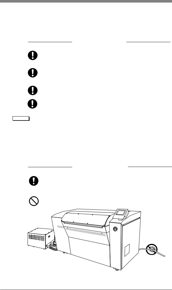
If you discover deformations, cracks, or cuts in the surface of a power cable or hose, immediately turn off the power switch, turn the building side power switches to OFF, and contact your nearest Dainippon Screen sales office or agent.
Do not step on or forcefully pull a power cable or hose.
Fig. 1-1 Power cable and hoses
1-4
Chapter 1 Ensuring Safety
2.3 Performing an Emergency Stop
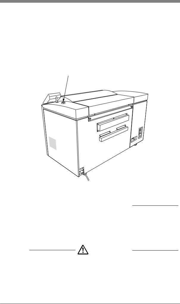
If trouble occurs during operation and you want to stop the PT-R immediately, press the forced drum stop switch.
When the forced drum stop switch is pressed, it takes approximately 4 seconds for the drum to stop rotating.
CAUTION! |
Do not use this switch during normal operation. This switch is only to be |
|
used if the drum needs to be stopped in case of an emergency. |
Forced drum stop switch
Fig. 1-2 Forced drum stop switch

 WARNING
In order to prevent accidents, be sure to turn off both the PT-R and building side power switches after work or before perforning maintenance or inspection procedures.
2.4 Handling Power Failures
WARNING
If a power failure in the external power supply occurs, turn off the PT-R and building side power switches in order to prevent accidents.
When the power is restored, turn on the building side power switch and turn the PT-R power switch ON again. For more details, refer to Chapter 4 “3. Turning the Power On and Off.”
1-5
PT-R4300 USERS MANUAL
3. General Precautions
 WARNING
Do not turn on the power switch of the PT-R or attempt operation until you have read this manual well and understand the contents.
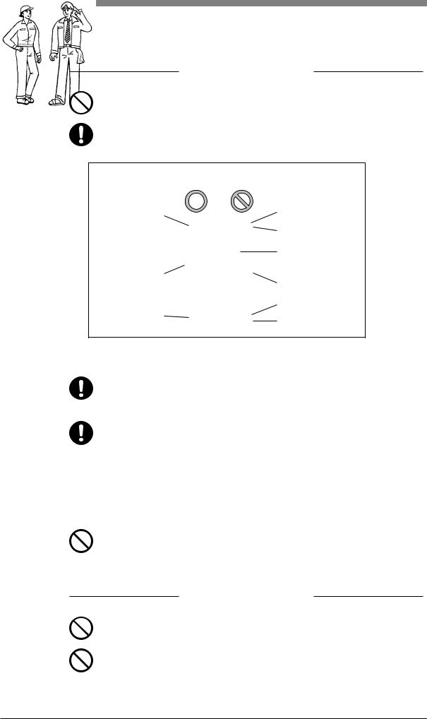
The operator should wear appropriate clothing.
Wear clothing that will not become caught in the machinery.
Long hair is tied |
Hands are wet. |
|
back. |
Cuffs are open. |
|
|
||
|
A necktie or necklace |
|
|
is dangling. |
|
Cuffs are buttoned. |
Unneeded things |
|
|
||
|
are carried. |
|
|
Excessively long |
|
Wear safety boots |
pants |
|
Slippers or sandals |
||
|
Fig. 1-3 Operator clothing
If you discover any abnormality or problem in the PT-R, contact your nearest Dainippon Screen office or agency to have appropriate measures taken.
Even in cases where the PT-R is capable of continuous operation, correct unattended operation is not guaranteed. A trained operator who is able to handle emergencies and initial safety measures must be present during operation in case an abnormal situation occurs. Our company offers courses on the proper handling of our products whenever needed. Please attend a course before attempting to operate the PT-R. Application for these courses can be made at any Dainippon Screen office or agency.
Do not attempt to operate the PT-R when you are not feeling well.
4. Maintenance
 WARNING
Only maintenance personnel who have received the specified training should perform maintenance work on the PT-R.
The operator should not under any circumstance turn on the building side and PT-R power switches when a maintenance technician is performing maintenance work.
1-6
Chapter 1 Ensuring Safety
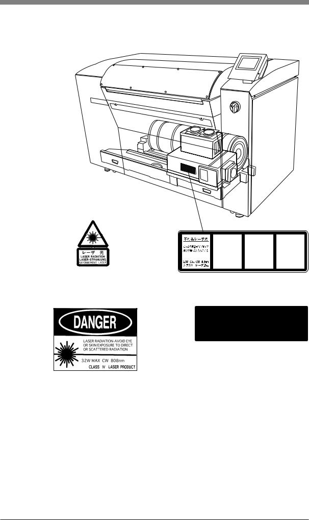
5. Warning and Caution Labels
To ensure safety, the following warning and caution labels are attached to parts of the PT-R that are potentially dangerous to operators and maintenance personnel. Observe the following safety rules when operating or performing maintenance work on the PT-R.
 WARNING
•Follow the instructions on all warning/caution labels.
•Do not erase or deface the instructions on a warning or caution label.
•Do not place objects in front of or cover a warning or caution label.
•If a warning or caution label has peeled off or is dirty, replace it with a new label. Failure to replace the label is extremely dangerous.
NOTE If you need a new warning or caution label, consult your nearest Dainippon Screen sales office or agent listed at the end of this manual.
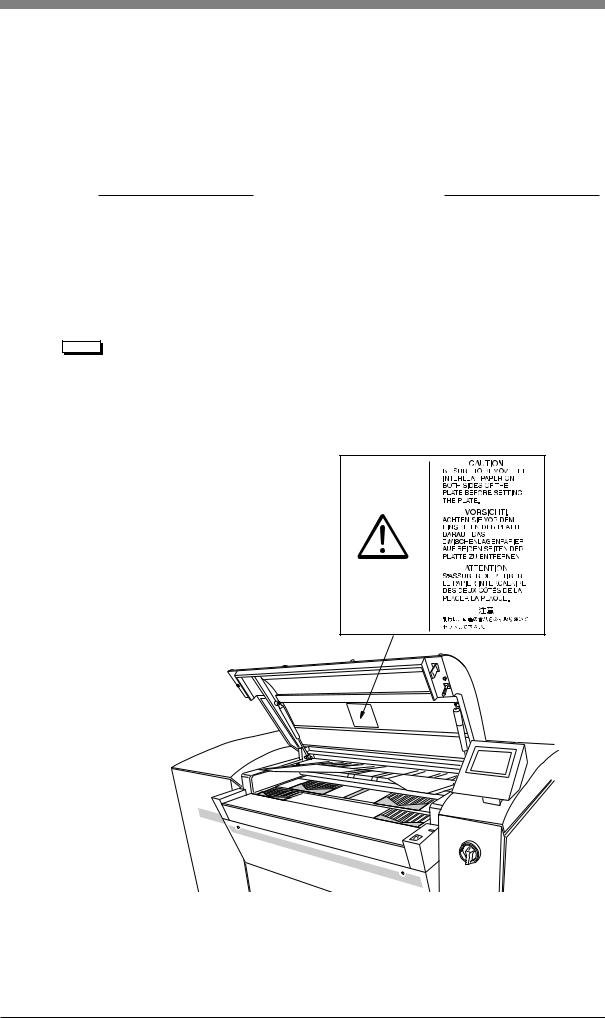
Fig. 1-4, 1-5, 1-6 and 1-7 below shows which labels are attached to the PT-R and where they are attached. Always follow the instructions on the labels when operating the PT-R.
This label reminds you to remove the interleaf papaer from both sides of the plate when you set the plate.
Fig. 1-4 Location of warning and caution labels (1)
1-7
PT-R4300 USERS MANUAL
Label indication that laser radiation exists inside
Label indicating that laser radiation exists inside.
INVISIBLE |
UNSICHTBAREN |
RAYONNEMENT LASER |
LASER RADIATION |
LASER-STRAHLUNG |
NON VISIBLE |
AVOID EYE OR SKIN |
BESTRAHLUNG VON AUGE |
EXPOSITION DANGEREUSE |
EXPOSURE TO DIRECT |
ODER HAUT DURCH |
DE L'CEIL OU DE LA PEAU |
OR SCATTERED RADIATION |
DIREKTE ODER STREUSTRAHLUNG |
AU RAYONNEMENT DIRECT |
|
VERMEIDEN ! |
OU DIFFUS |
32W MAX CW 808nm |
32W MAX CW 808nm |
32W MAX CW 808nm |
CLASS 4 LASER PRODUCT |
LASER KLASSE 4 |
APPAREIL Á LASER DE CLASSE 4 |
Label indicating the class, power, and wave length of the laser
|
|
DANGER |
|
VORSICHT! |
|
ATTENTION |
|
|
INVISIBLE LASER |
|
UNSICHTBARE |
|
RAYONNEMENT LASER |
|
|
RADIATION WHEN |
|
LASERSTRAHLEN, WENN |
|
NON VISIBLE DANGEREUX |
|
|
OPEN AND INTERLOCKS |
|
GEOFFNET UND |
|
EN CAS D’ OUVERTURE |
|
|
DEFEATED. |
|
SICHERHEITSSCHALTER |
|
ET LORSQUE LA SECURITE |
|
|
AVOID EYE OR SKIN |
|
DEAKTIVIERT SIND. |
|
EST NEUTRALISEE. |
|
|
EXPOSURE TO DIRECT |
|
VERMEIDEN SIE DIREKTE |
|
EVITER UN CONTACT |
|
|
OR SCATTERED |
|
ODER INDIREKTE |
|
DIRECT OU DIFFUS AVEC |
|
|
RADIATION. |
|
BESTRAHLUNG VON |
|
L’ OEIL OU LA PEAU. |
|
|
|
|
AUGEN UND HAUTI |
|
|
|
|
|
|
|
|
|
This label warns you that releasing an interlock whilean operation door with this label attached is opened may expose you to dangerous invisible laser radiation.
Fig. 1-5 Location of warning and caution labels (2)
1-8

Chapter 1 Ensuring Safety
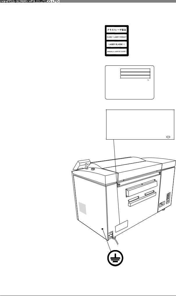
Label indicating that laser radiation exists inside.
Label indicating the existence of a alaser aperture where the label is attached.
Label indicating high leakage current.
Label indicating that the product meets the requirements for CE marking.
Label indicating that
the product complies with FCC rules.
This device complies with Part 15 of the FCC Rules. |
|
Operation is subject to the following two conditions: |
|
(1) this device may not cause harmful interference, and |
|
(2) this device must accept any interference received, |
|
including interference that may cause undesired |
|
operation. |
VCCI-1 |
This Class A digital appartus meets all requirements of the Canadian interference-Causing Equipment Regulations. Cet appareil numerique de la Clase A respecte toutes les exigences du Regiemental sur le material brouilleur du
Canada. T
Fig. 1-6 Location of warning and caution labels (3)
1-9
PT-R4300 USERS MANUAL
Label indicating that
this is a Class 1 Laser Product
Label indicating the power specifications.
Label indicating that the product conforms to CDRH regulations.
M O D E L
MFG.No.
D A T E
|
V O L T S |
|
|
V |
|
||||
|
|
|
|
|
|
|
|
|
|
|
A M P S . |
|
|
|
|
A |
|
||
|
P H A S E |
|
|
|
Hz |
|
kW |
||
|
|
|
|
|
|
||||
|
|
|
|
|
|
|
|
|
|
|
|
|
|
|
|
|
|
|
|
|
|
|
MADE IN JAPAN |
|
Z830B-L8 |
||||
304 sinkaichi, sayama, kumiyama-cho, kuze-gun, kyoto 613, Japan
MODEL NUMBER: |
PT - R 4 3 0 0 |
VOLTAGE RATING: |
200-240VAC |
THIS PRODUCT CONFORMS TO DHHS REGULATIONS AS APPLICABLE
TO STANDARDS 21 CFR CHAPTER I SUBCHAPTER J |
|
MADE IN JAPAN |
T |
This label is attached near the ground terminal to allow easy identification of the ground terminal in the PT-R.
Fig. 1-7 Location of warning and caution labels (4)
1-10
Chapter 1 Ensuring Safety
6. Interlock System
The PT-R is equipped with an interlock system to protect the operator. When any of the doors is opened, the interlock switch placed at the door activates and cuts off the laser light.
 WARNING
With the exception of times when maintenance personnel are performing maintenance procedures, do not disengage the interlocks. Operating the PT-R with the interlocks disengaged may result in serious personal injury.
If any of the doors are opened during exposure, the interlocks will activate and automatically stop the rotation of the rollers, main drum, and feed section, as well as the movement of the transfer unit. However, approximately 4 seconds is required for the main drum to come to a complete stop. Do not under any circumstance touch the main drum until it has come to a complete stop.
Switch for operation door
Switch for front cover
Fig. 1-8 Interlock switches (front)
1-11

PT-R4300 USERS MANUAL
|
|
|
Soft switch for |
Interlock switch for |
|
drum slowdown |
||
left side cover |
||
|
Interlock switch for rear cover
Fig. 1-9 Interlock switches (rear)
Interlock switch for right side cover
Fig. 1-10 Interlock switches (right side)
1-12

Chapter 1 Ensuring Safety
7. Disposal of the PT-R
 WARNING
When disassembling the PT-R there are dangerous parts such as the gas spring in the open/close part of the operation door. Because of the danger present when disassembling the PT-R no one other than a specialized engineer who was properly trained at Dainippon Screen should carry this out.
Handling plate and plate punch debris
Please acquire the services of a professional recycling company to take care of used plates and plate punch debris.
Lithium battery handling
A lithium battery is used in the control panel of the PT-R. Under normal use the lithium battery has a life of five to ten years. When it expires it should be disposed of carefully using special procedures for handling harmful substances. When disposing of the PT-R please contact the place of purchase or use the contact information at the end of this manual to request the services of specialized lithium battery removal and disposal personnel.
Disposal of replacement parts and the PT-R itself
When disposing replacement parts or the PT-R itself, please seek advice from the place of purchase or the contact information at the end of this manual, or request the services of a professional disposal company that specializes in recycling.
If you have any questions regarding disposal, please consult the place of purchase or contact the Dainippon Screen sales office or agency listed at the end of this manual.
1-13

PT-R4300 USERS MANUAL
8. Environmental Protection
In March of 2001, Dainippon Screen and all its manufacturing facilities, including affiliate companies, acquired ISO14001 Environment Management System certification. Further to this, Dainippon Screen has and still continues to do its best for environmental preservation by promoting manufacturing practices that do not harm on the environment.
NOTE ISO14001 Environment Management System is an international standard designed to preserve the environment. It places emphasis on the initiative of corporations and organizations to take responsibility for and to actively engage in activities for this purpose. In addition to requiring that environmental regulations be observed and that the environmental impact of corporate activities be reduced, it continually evolves, in accordance with its unique environmental policy, through the formulation, execution, practical review, and amendment of goals. It efficiently promotes activities for environmental preservation by getting manufacturers actively involved in environmental issues and also by obtaining the cooperation of customers through information they provide.
The following are requirements regarding product use and disposal for environmental preservation. Please read thoroughly and faithfully observe the contents in the same manner as you would for safety related cautions.
Environmental regulations
Laws, enforcement ordinances, enforcement regulations and bylaws exist that are meant to protect the environment. Please consult your national, state/province or local government for more information about these and the punishments involved.
Handling of waste Iitem(s) for disposal
Please use the services of a professional disposal company according to the following procedure.
1.Verify that the item(s) to be disposed of is included in the items approved (type of item, type of business, and conditions of authorization) by the national, state/province or local government for disposal by the company in question.
2.Conclude agreements for commission of authority to collect and transport, and commission of authority to dispose.
3.Consign the item(s) for disposal and, if necessary, submit a disposal report to your national, state/provincial or local government.
4.Obtain transport completion and disposal completion documents from the disposal company to verify that the disposal was properly completed.
5.Visit the disposal company and verify that the work was conducted properly according to contract.
1-14

Chapter 1 Ensuring Safety
Handling of dangerous and toxic waste
The following procedures are required, in addition to the usual handling procedure by disposal companies, for waste such as that which is explosive, poisonous, contagious, or otherwise potentially dangerous to human health or to the environment.
•Verify that the disposal company is properly certified by the national, state/ provincial or local government to take responsibility for the handling of dangerous and toxic waste.
•Label the item for disposal to indicate what it is and to indicate that it is a dangerous and/or toxic waste. Making sure it will be distinguished from other waste, request the storage and processing services of the disposal company.
•Submit your official report for disposal of dangerous and toxic wastes by the required date to the applicable department of your national, state/provincial or local government.
Handling of valuable resources
Although materials that can be recycled such as plates (PS plates) do not classify as waste, they should be treated as industrial waste if they will be disposed of as garbage.
1-15
PT-R4300 USERS MANUAL
|
|
|
|
1-16 |
End of Chapter 1 |

2
Chapter 2
Installing and Moving
the PT-R
This chapter explains precautions for installing and moving
the PT-R.
PT-R4300 USERS MANUAL
1. Installing and Moving the PT-R4300
Installation and moving of the PT-R must be performed by a Dainippon Screen appointed service comapny or service technician. Dainippon Screen bears absolutely no responsibility for any damage, breakdowns, or malfunctioning resulting from installation or moving by anyone other than a Dainippon Screen appointed service comapny or service technician, and Dainippon Screen extends no guarantees regarding safety in such a case. If you need to have the PT-R moved or installed, consult one of the Dainippon Screen offices or agency listed at the end of this manual.
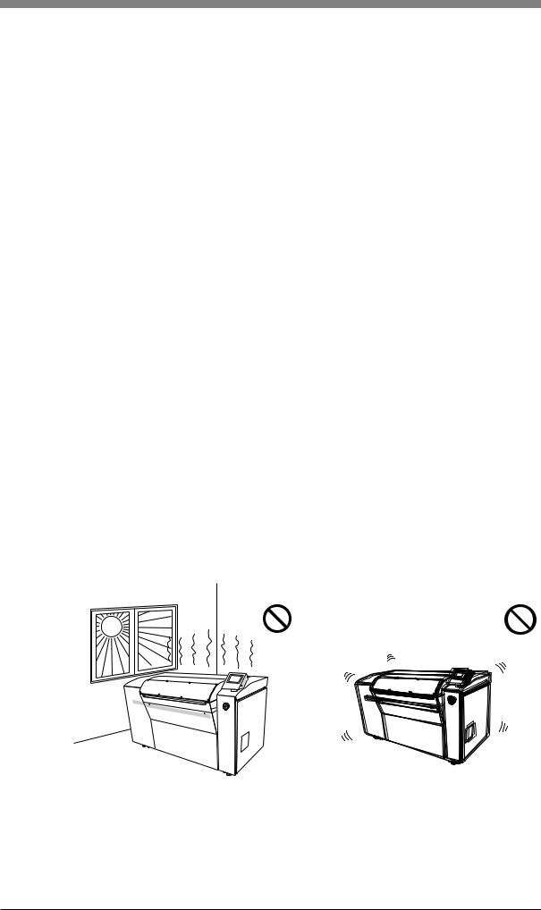
2. Installation Location
Do not install the PT-R in any of the following locations, as safety problems, failures, and malfunctioning may result.
•Locations directly exposed to sunlight
•Locations where electrical interference (voltage fluctuations or noise) may occur
•Locations close to machines that emit strong magnetic fields.
•Locations subject to sudden changes of temperature
•Locations close to sources of heat
•Locations with high temperature or high humidity
•Locations subject to vibration
•Unstable locations where the floor is not level
•Locations with dust
•Location subject to condensation
•Locations where the PT-R might be exposed to chemical solutions, smoke, volatile gases, or corrosive gases.
|
|
|
|
|
|
|
|
|
|
|
|
|
|
|
High temperature, high humidity |
Vibrations, unstable |
|||
Fig. 2-1 Bad installation locations
2-2
Chapter 2 Installing and Moving the PT-R
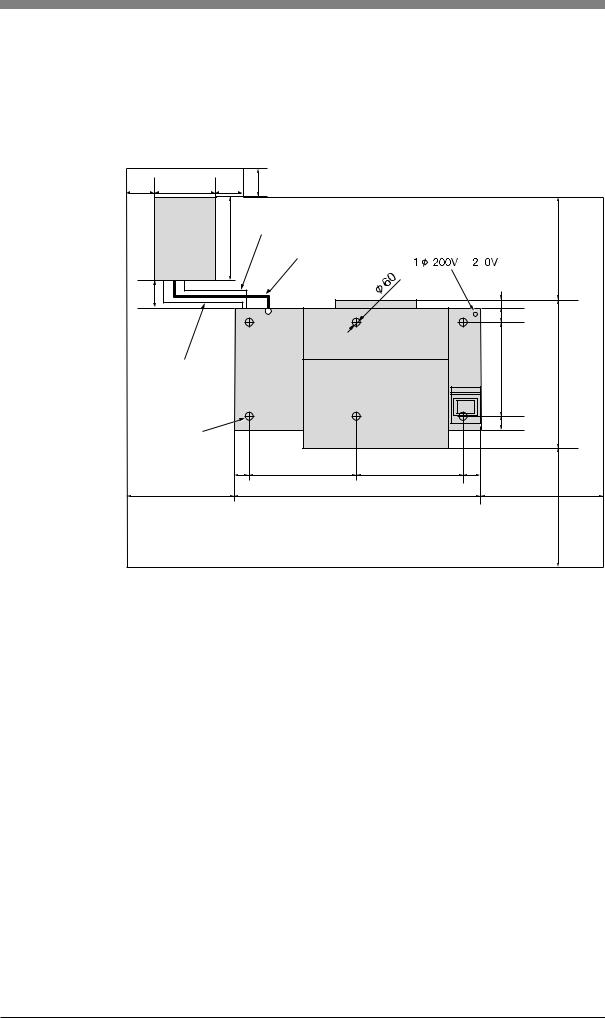
3. Space Required for Installation
To allow escape in the event of danger and enable access for maintenance, leave at least 800 mm open around the periphery of the PT-R. Keep the floor free of obstacles and keep a path to the building side power switch clear.
200 |
429 |
200 |
200 |
|
|
|
|
|
Blower |
600 |
Communication cable (2 m) |
|
|
|
|
|
|
|
|
|
800 |
||
|
|
Vacuum hose (2 m) |
to |
4 |
|||
|
|
|
|
||||
|
|
|
|
|
|
||
200 |
|
|
|
|
|
|
45 |
|
|
|
|
|
|
|
|
|
|
|
|
|
|
|
97.5 |
|
|
|
|
PT-R4300 |
|
|
|
Power cable |
|
|
|
|
655 |
1030 |
|
for blower (2 m) |
|
|
|
||||
|
|
|
|
|
|
|
107.5 |
Adjuster foot |
|
|
|
|
|
|
|
|
|
125 |
750 |
750 |
125 |
|
|
|
800 |
|
|
1750 |
|
|
1000 |
|
|
|
|
|
|
|
1000 |
(Units: mm) |
|
|
|
|
|
|
|
|
|
|
Fig. 2-2 |
Installation space |
|
|
|
CAUTION! |
• Keep 200 mm open around the periphery of the blower to allow heat |
|
dissipation. |
• A 2-meter vacuum hose is supplied with the PT-R. Do not use a hose different from the hose that is supplied hose, even if you require a hose of different length. Pressures losses caused by a different hose may adversely affect the operation of the blower and cause a malfunction.
2-3

PT-R4300 USERS MANUAL
4. Load Tolerance of Building
The site of installation requires a floor load tolerance of at least 4010 N/m2 (410 kgf/ m2) . To prevent the formation of cracks in the floor, it is recommended that the adjuster foot of the PT-R rest on the framework of the building; however, the load on the floor will vary depending on the strength of the floor, the position of the framework, the positioning of the PT-R, and the presence of other heavy objects in the same location. Consult with the designer of the building or other authority.
5.Ground Connections
•In order to prevent electrical shock accidents from the AC power supply, perform grounding connections for the machine only after making sure that the PT-R power switch and the building side power switch are both off.
•Since the leakage current of the PT-R is max. 3.5 mA, be sure to conduct grounding before connecting the power line of the PT-R 3-line cable.
Have a qualified electrician select the above items and perform the connections.
6.Power Supply and Power Cables
•Have electrical work performed by a qualified electrician.
•Make arrangements to obtain the power supply indicated in Chapter 9, “Technical Information.”
•PT-R power is supplied independently from the building side power switch, therefore do not connect other devices to that power switch.
•The allowed range of voltage fluctuation in 200 V-240 V power supply areas is +6%, -10%. If fluctuations in the power supply are greater than this, use a stabilizer.
•A power cable is not provided with products sold outside of Japan. For the PT-R, please obtain an 2.5 mm2 × 3-wire power supply cable that complies with the standards of your country and is rated at 300 V AC or higher.
If the cable described above does not comply to the standards of the country of installation, please refer to the power supply nameplate attached to the PT-R and provide a cable locally that does comply.
CAUTION! |
A readily accessible disconnection device (building side power switch) |
|
must be installed in the fixed building wiring before installing the PT-R. |
2-4 |
End of Chapter 2 |
 Loading...