

Daikin VAM350J7VEB, VAM500J7VEB, VAM650J7VEB, VAM800J7VEB, VAM1000J7VEB Installer reference guide
...
Name Plate
Installer and user
reference guide
Heat reclaim ventilation unit
VAM350J7VEB
VAM500J7VEB
VAM650J7VEB
VAM800J7VEB
VAM1000J7VEB
VAM1500J7VEB
VAM2000J7VEB
Installer and user reference guide
Heat reclaim ventilation unit
English

Table of contents
Table of contents
1 General safety precautions 3
1.1 About the documentation .......................................................... 3
1.1.1 Meaning of warnings and symbols.............................. 3
1.2 For the user ............................................................................... 3
1.3 For the installer.......................................................................... 3
1.3.1 General ....................................................................... 3
1.3.2 Installation site ............................................................ 4
1.3.3 Refrigerant .................................................................. 4
1.3.4 Brine............................................................................ 5
1.3.5 Water .......................................................................... 5
1.3.6 Electrical ..................................................................... 5
2 About the documentation 6
2.1 About this document.................................................................. 6
For the installer 6
3 About the box 6
3.1 Overview: About the box ........................................................... 6
3.2 Heat reclaim ventilation unit ...................................................... 7
3.2.1 To unpack the heat reclaim ventilation unit................. 7
3.2.2 To remove the accessories......................................... 8
3.2.3 To handle the heat reclaim ventilation unit ................. 8
4 About the units and options 9
4.1 Overview: About the units and options...................................... 9
4.2 Identification .............................................................................. 9
4.2.1 Identification label: Heat reclaim ventilation unit......... 9
4.3 About the heat reclaim ventilation unit ...................................... 9
4.4 Combining units and options ..................................................... 9
4.4.1 Possible options for the heat reclaim ventilation unit.. 9
5 Preparation 10
5.1 Overview: Preparation............................................................... 10
5.2 Preparing the installation site .................................................... 10
5.2.1 Installation site requirements for the heat reclaim
ventilation unit ............................................................. 10
5.3 Preparing the unit ...................................................................... 10
5.3.1 To install the optional adapter printed circuit board .... 10
5.3.2 To install the duct joints .............................................. 11
5.4 Preparing the electrical wiring ................................................... 11
5.4.1 Wiring connection ....................................................... 11
5.4.2 Component electrical specifications............................ 12
5.4.3 Specifications for field supplied fuses and wires......... 12
5.5 Preparing the installation of the ducts ....................................... 13
6 Installation 13
6.1 Service space: Heat reclaim ventilation unit.............................. 13
6.2 Unit orientation .......................................................................... 13
6.3 To install the anchor bolts ......................................................... 14
6.4 Duct connections....................................................................... 14
6.5 Electrical wiring ......................................................................... 15
6.5.1 Precautions when connecting electrical wiring ........... 15
6.5.2 Opening the switch box............................................... 16
6.5.3 Electrical connections for possible additional field
supplied damper ......................................................... 19
6.5.4 Power supply connection, control wire terminals and
switches on the circuit board....................................... 19
6.5.5 Guidelines when connecting the electrical wiring ....... 19
7 System configuration 20
7.1 About control systems ............................................................... 20
7.2 Independent system .................................................................. 21
7.3 Interlocked system .................................................................... 21
7.4 Centralised control system ........................................................ 22
8 Configuration 22
8.1 Operating procedure .................................................................. 22
8.1.1 To change the settings with BRC1E53 ........................ 22
8.1.2 To change the settings with BRC301B61 .................... 23
8.2 List of settings ............................................................................ 24
8.3 Settings for all configurations ..................................................... 28
8.3.1 About setting 19(29)-0-04 and 19(29)-0-05 ................. 28
8.3.2 Independent system..................................................... 29
8.3.3 1-group linked-control system...................................... 29
8.3.4 Linked control with more than 2 groups ....................... 29
8.3.5 Direct duct connection ................................................. 30
8.3.6 Centralised control system........................................... 30
8.4 About the user interface ............................................................. 32
8.4.1 User interface for VRV-system air conditioner............. 32
8.4.2 User interface for heat reclaim ventilation units ........... 33
8.5 Detailed explanation of settings ................................................. 34
8.5.1 To monitor the unit's operation..................................... 34
8.5.2 About the fresh-up operation ....................................... 34
8.5.3 About the external damper operation........................... 35
8.5.4 About the carbon dioxide sensor ................................. 35
8.5.5 About the nighttime free cooling operation .................. 37
8.5.6 About the pre-cool and pre-heat function..................... 37
8.5.7 About preventing a feeling of draft............................... 37
8.5.8 About 24-hour ventilation ............................................. 37
8.5.9 About the ultra-low setting ........................................... 37
8.5.10 About the electrical heater operation ........................... 38
8.5.11 About external linkage input......................................... 38
8.5.12 About filter contamination check .................................. 38
9 Commissioning 38
9.1 Overview: Commissioning.......................................................... 38
9.2 Precautions when commissioning .............................................. 38
9.3 Checklist before commissioning................................................. 38
9.4 Checklist during commissioning ................................................. 38
9.4.1 About the test run......................................................... 38
10 Hand-over to the user 39
11 Maintenance and service 39
11.1 Overview: Maintenance and service .......................................... 39
11.2 Maintenance safety precautions................................................. 39
11.2.1 To prevent electrical hazards ....................................... 39
11.3 Checklist for maintenance of the heat reclaim ventilation unit ... 39
12 Troubleshooting 39
12.1 Overview: Troubleshooting......................................................... 39
12.2 Precautions when troubleshooting ............................................. 40
12.3 Solving problems based on error codes ..................................... 40
12.3.1 Error codes: Overview ................................................. 40
13 Disposal 40
14 Technical data 40
14.1 Wiring diagram: Heat reclaim ventilation unit ............................. 40
For the user 41
15 User interface 41
16 Before operation 41
17 Energy saving and optimum operation 41
18 Maintenance and service 42
18.1 Maintenance of the air filter ........................................................ 42
18.2 Maintenance of the heat exchange element .............................. 43
19 Troubleshooting 43
20 Relocation 43
21 Disposal 43
Installer and user reference guide
2
VAM350~2000J7VEB
Heat reclaim ventilation unit
4P487293-1 – 2017.08
1 General safety precautions
22 Glossary 43
1 General safety precautions
1.1 About the documentation
▪ The original documentation is written in English. All other
languages are translations.
▪ The precautions described in this document cover very important
topics, follow them carefully.
▪ The installation of the system, and all activities described in the
installation manual and the installer reference guide MUST be
performed by an authorised installer.
1.1.1 Meaning of warnings and symbols
DANGER
Indicates a situation that results in death or serious injury.
DANGER: RISK OF ELECTROCUTION
Indicates a situation that could result in electrocution.
DANGER: RISK OF BURNING
Indicates a situation that could result in burning because of
extreme hot or cold temperatures.
DANGER: RISK OF EXPLOSION
Indicates a situation that could result in explosion.
WARNING
Indicates a situation that could result in death or serious
injury.
WARNING: FLAMMABLE MATERIAL
CAUTION
Indicates a situation that could result in minor or moderate
injury.
NOTICE
Indicates a situation that could result in equipment or
property damage.
a safe way and understand the hazards involved. Children shall
NOT play with the appliance. Cleaning and user maintenance
shall NOT be made by children without supervision.
WARNING
To prevent electric shocks or fire:
▪ Do NOT rinse the unit.
▪ Do NOT operate the unit with wet hands.
▪ Do NOT place any objects containing water on the unit.
NOTICE
▪ Do NOT place any objects or equipment on top of the
unit.
▪ Do NOT sit, climb or stand on the unit.
▪ Units are marked with the following symbol:
This means that electrical and electronic products may NOT be
mixed with unsorted household waste. Do NOT try to dismantle
the system yourself: the dismantling of the system, treatment of
the refrigerant, of oil and of other parts must be done by an
authorized installer and must comply with applicable legislation.
Units must be treated at a specialized treatment facility for reuse,
recycling and recovery. By ensuring this product is disposed of
correctly, you will help to prevent potential negative consequences
for the environment and human health. For more information,
contact your installer or local authority.
▪ Batteries are marked with the following symbol:
This means that the batteries may NOT be mixed with unsorted
household waste. If a chemical symbol is printed beneath the
symbol, this chemical symbol means that the battery contains a
heavy metal above a certain concentration.
Possible chemical symbols are: Pb: lead (>0.004%).
Waste batteries must be treated at a specialized treatment facility
for reuse. By ensuring waste batteries are disposed of correctly,
you will help to prevent potential negative consequences for the
environment and human health.
1.3 For the installer
INFORMATION
Indicates useful tips or additional information.
Symbol Explanation
Before installation, read the installation and
operation manual, and the wiring instruction sheet.
Before performing maintenance and service tasks,
read the service manual.
For more information, see the installer and user
reference guide.
1.2 For the user
▪ If you are NOT sure how to operate the unit, contact your installer.
▪ This appliance can be used by children aged from 8 years and
above and persons with reduced physical, sensory or mental
capabilities or lack of experience and knowledge if they have been
given supervision or instruction concerning use of the appliance in
VAM350~2000J7VEB
Heat reclaim ventilation unit
4P487293-1 – 2017.08
1.3.1 General
If you are NOT sure how to install or operate the unit, contact your
dealer.
NOTICE
Improper installation or attachment of equipment or
accessories could result in electric shock, short-circuit,
leaks, fire or other damage to the equipment. Only use
accessories, optional equipment and spare parts made or
approved by Daikin.
WARNING
Make sure installation, testing and applied materials
comply with applicable legislation (on top of the
instructions described in the Daikin documentation).
CAUTION
Wear adequate personal protective equipment (protective
gloves, safety glasses,…) when installing, maintaining or
servicing the system.
Installer and user reference guide
3
1 General safety precautions
WARNING
Tear apart and throw away plastic packaging bags so that
nobody, especially children, can play with them. Possible
risk: suffocation.
DANGER: RISK OF BURNING
▪ Do NOT touch the refrigerant piping, water piping or
internal parts during and immediately after operation. It
could be too hot or too cold. Give it time to return to
normal temperature. If you must touch it, wear
protective gloves.
▪ Do NOT touch any accidental leaking refrigerant.
WARNING
Provide adequate measures to prevent that the unit can be
used as a shelter by small animals. Small animals that
make contact with electrical parts can cause malfunctions,
smoke or fire.
CAUTION
Do NOT touch the air inlet or aluminium fins of the unit.
NOTICE
▪ Do NOT place any objects or equipment on top of the
unit.
▪ Do NOT sit, climb or stand on the unit.
NOTICE
Works executed on the outdoor unit are best done under
dry weather conditions to avoid water ingress.
In accordance with the applicable legislation, it might be necessary
to provide a logbook with the product containing at least: information
on maintenance, repair work, results of tests, stand-by periods,…
Also, at least, following information MUST be provided at an
accessible place at the product:
▪ Instructions for shutting down the system in case of an emergency
▪ Name and address of fire department, police and hospital
▪ Name, address and day and night telephone numbers for
obtaining service
In Europe, EN378 provides the necessary guidance for this logbook.
1.3.2 Installation site
▪ Provide sufficient space around the unit for servicing and air
circulation.
▪ Make sure the installation site withstands the unit's weight and
vibration.
▪ Make sure the area is well ventilated. Do NOT block any
ventilation openings.
▪ Make sure the unit is level.
Do NOT install the unit in the following places:
▪ In potentially explosive atmospheres.
▪ In places where there is machinery that emits electromagnetic
waves. Electromagnetic waves may disturb the control system,
and cause malfunction of the equipment.
▪ In places where there is a risk of fire due to the leakage of
flammable gases (example: thinner or gasoline), carbon fibre,
ignitable dust.
▪ In places where corrosive gas (example: sulphurous acid gas) is
produced. Corrosion of copper pipes or soldered parts may cause
the refrigerant to leak.
1.3.3 Refrigerant
If applicable. See the installation manual or installer reference guide
of your application for more information.
NOTICE
Make sure refrigerant piping installation complies with
applicable legislation. In Europe, EN378 is the applicable
standard.
NOTICE
Make sure the field piping and connections are NOT
subjected to stress.
WARNING
During tests, NEVER pressurize the product with a
pressure higher than the maximum allowable pressure (as
indicated on the nameplate of the unit).
WARNING
Take sufficient precautions in case of refrigerant leakage. If
refrigerant gas leaks, ventilate the area immediately.
Possible risks:
▪ Excessive refrigerant concentrations in a closed room
can lead to oxygen deficiency.
▪ Toxic gas may be produced if refrigerant gas comes
into contact with fire.
DANGER: RISK OF EXPLOSION
Pump down – Refrigerant leakage. If you want to pump
down the system, and there is a leakage in the refrigerant
circuit:
▪ Do NOT use the unit's automatic pump down function,
with which you can collect all refrigerant from the
system into the outdoor unit. Possible consequence:
Self-combustion and explosion of the compressor
because of air going into the operating compressor.
▪ Use a separate recovery system so that the unit's
compressor does NOT have to operate.
WARNING
ALWAYS recover the refrigerant. Do NOT release them
directly into the environment. Use a vacuum pump to
evacuate the installation.
NOTICE
After all the piping has been connected, make sure there is
no gas leak. Use nitrogen to perform a gas leak detection.
NOTICE
▪ To avoid compressor breakdown, do NOT charge more
than the specified amount of refrigerant.
▪ When the refrigerant system is to be opened,
refrigerant MUST be treated according to the applicable
legislation.
WARNING
Make sure there is no oxygen in the system. Refrigerant
may only be charged after performing the leak test and the
vacuum drying.
▪ In case re-charge is required, refer to the nameplate of the unit. It
states the type of refrigerant and necessary amount.
▪ The unit is factory charged with refrigerant and depending on pipe
sizes and pipe lengths some systems require additional charging
of refrigerant.
Installer and user reference guide
4
VAM350~2000J7VEB
Heat reclaim ventilation unit
4P487293-1 – 2017.08
1 General safety precautions
▪ Only use tools exclusively for the refrigerant type used in the
system, this to ensure pressure resistance and prevent foreign
materials from entering into the system.
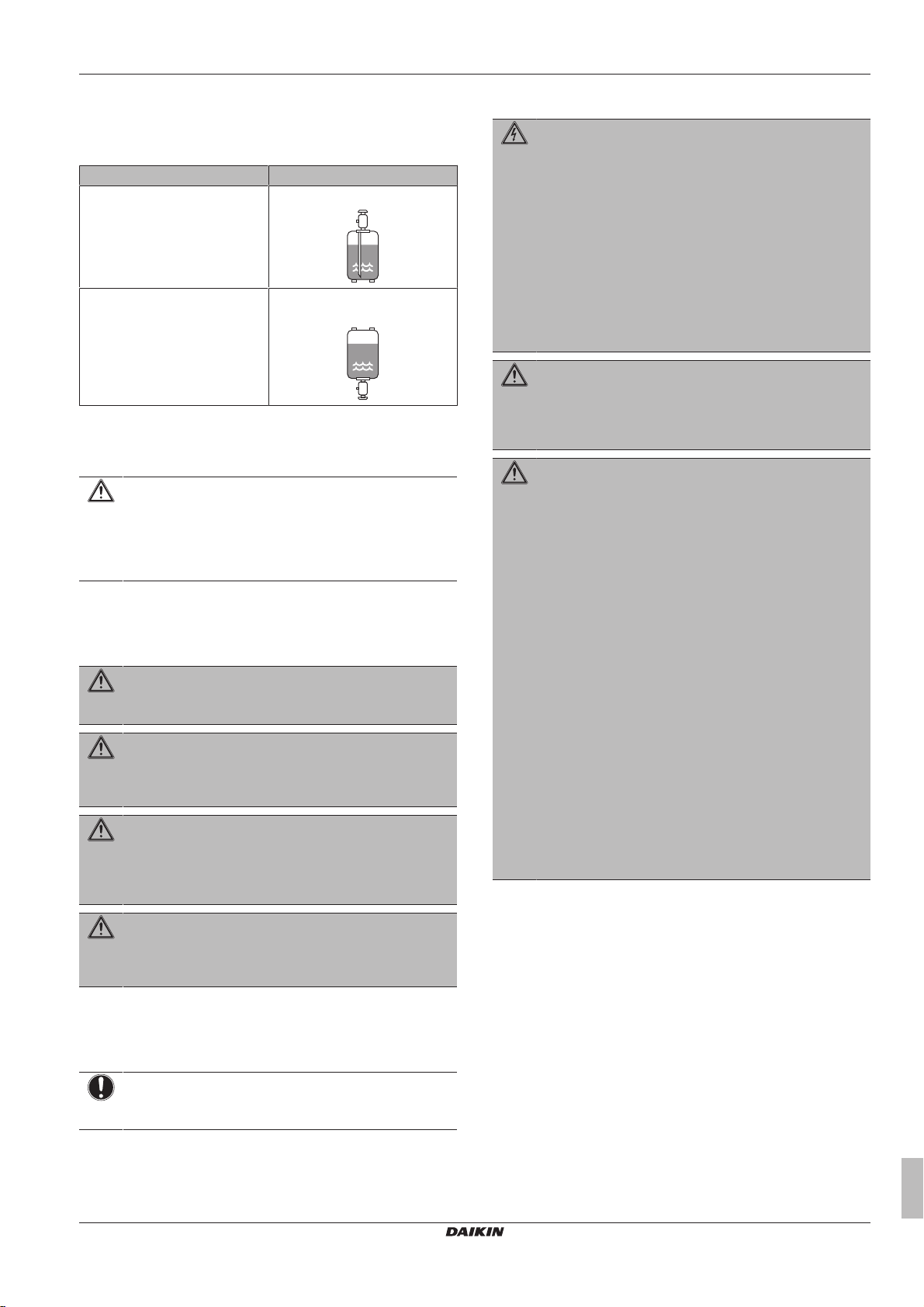
▪ Charge the liquid refrigerant as follows:
If Then
A siphon tube is present
(i.e., the cylinder is marked with
"Liquid filling siphon attached")
A siphon tube is NOT present Charge with the cylinder upside
▪ Open refrigerant cylinders slowly.
▪ Charge the refrigerant in liquid form. Adding it in gas form may
prevent normal operation.
CAUTION
When the refrigerant charging procedure is done or when
pausing, close the valve of the refrigerant tank
immediately. If the valve is NOT closed immediately,
remaining pressure might charge additional refrigerant.
Possible consequence: Incorrect refrigerant amount.
Charge with the cylinder upright.
down.
1.3.4 Brine
If applicable. See the installation manual or installer reference guide
of your application for more information.
WARNING
The selection of the brine MUST be in accordance with the
applicable legislation.
WARNING
Take sufficient precautions in case of brine leakage. If
brine leaks, ventilate the area immediately and contact
your local dealer.
WARNING
The ambient temperature inside the unit can get much
higher than that of the room, e.g. 70°C. In case of a brine
leak, hot parts inside the unit can create a hazardous
situation.
1.3.6 Electrical
DANGER: RISK OF ELECTROCUTION
▪ Turn OFF all power supply before removing the
switch box cover, connecting electrical wiring or
touching electrical parts.
▪ Disconnect the power supply for more than 1 minute,
and measure the voltage at the terminals of main circuit
capacitors or electrical components before servicing.
The voltage MUST be less than 50 V DC before you
can touch electrical components. For the location of the
terminals, see the wiring diagram.
▪ Do NOT touch electrical components with wet hands.
▪ Do NOT leave the unit unattended when the service
cover is removed.
WARNING
If NOT factory installed, a main switch or other means for
disconnection, having a contact separation in all poles
providing full disconnection under overvoltage category III
condition, MUST be installed in the fixed wiring.
WARNING
▪ ONLY use copper wires.
▪ Make sure the field wiring complies with the applicable
legislation.
▪ All field wiring MUST be performed in accordance with
the wiring diagram supplied with the product.
▪ NEVER squeeze bundled cables and make sure they
do NOT come in contact with the piping and sharp
edges. Make sure no external pressure is applied to the
terminal connections.
▪ Make sure to install earth wiring. Do NOT earth the unit
to a utility pipe, surge absorber, or telephone earth.
Incomplete earth may cause electrical shock.
▪ Make sure to use a dedicated power circuit. NEVER
use a power supply shared by another appliance.
▪ Make sure to install the required fuses or circuit
breakers.
▪ Make sure to install an earth leakage protector. Failure
to do so may cause electric shock or fire.
▪ When installing the earth leakage protector, make sure
it is compatible with the inverter (resistant to high
frequency electric noise) to avoid unnecessary opening
of the earth leakage protector.
WARNING
The use and installation of the application MUST comply
with the safety and environmental precautions specified in
the applicable legislation.
1.3.5 Water
If applicable. See the installation manual or installer reference guide
of your application for more information.
NOTICE
Make sure water quality complies with EU directive
98/83EC.
VAM350~2000J7VEB
Heat reclaim ventilation unit
4P487293-1 – 2017.08
Installer and user reference guide
5
2 About the documentation
NOTICE
Precautions when laying power wiring:
▪ Do NOT connect wiring of different thicknesses to the
power terminal block (slack in the power wiring may
cause abnormal heat).
▪ When connecting wiring which is the same thickness,
do as shown in the figure above.
▪ For wiring, use the designated power wire and connect
firmly, then secure to prevent outside pressure being
exerted on the terminal board.
▪ Use an appropriate screwdriver for tightening the
terminal screws. A screwdriver with a small head will
damage the head and make proper tightening
impossible.
▪ Over-tightening the terminal screws may break them.
WARNING
▪ After finishing the electrical work, confirm that each
electrical component and terminal inside the electrical
components box is connected securely.
▪ Make sure all covers are closed before starting up the
unit.
NOTICE
Only applicable if the power supply is three‑phase, and the
compressor has an ON/OFF starting method.
If there exists the possibility of reversed phase after a
momentary black out and the power goes on and off while
the product is operating, attach a reversed phase
protection circuit locally. Running the product in reversed
phase can break the compressor and other parts.
Target audience
Authorised installers + end users
INFORMATION
This appliance is intended to be used by expert or trained
users in shops, in light industry and on farms, or for
commercial use by lay persons.
Documentation set
This document is part of a documentation set. The complete set
consists of:
▪ General safety precautions:
▪ Safety instructions that you MUST read before installing
▪ Format: Paper (in the accessory bag of the heat reclaim
ventilation unit)
▪ Heat reclaim ventilation unit installation and operation
manual:
▪ Installation and operation instructions
▪ Format: Paper (in the accessory bag of the heat reclaim
ventilation unit)
▪ Installer and user reference guide:
▪ Preparation of the installation, good practices, reference data,…
▪ Detailed step-by-step instructions and background information
for basic and advanced usage
▪ Format: Digital files on http://www.daikineurope.com/support-
and-manuals/product-information/
Latest revisions of the supplied documentation may be available on
the regional Daikin website or via your dealer.
The original documentation is written in English. All other languages
are translations.
Technical engineering data
▪ A subset of the latest technical data is available on the regional
Daikin website (publicly accessible).
▪ The full set of latest technical data is available on the Daikin
extranet (authentication required).
2 About the documentation
2.1 About this document
INFORMATION
Make sure that the user has the printed documentation and
ask him/her to keep it for future reference.
For the installer
3 About the box
3.1 Overview: About the box
This chapter describes what you have to do after the box with the
heat reclaim ventilation unit is delivered on-site.
It contains information about:
▪ Unpacking and handling the units
▪ Removing the accessories from the units
Keep the following in mind:
▪ At delivery, the unit MUST be checked for damage. Any damage
MUST be reported immediately to the carrier's claims agent.
▪ Bring the packed unit as close as possible to its final installation
position to prevent damage during transport.
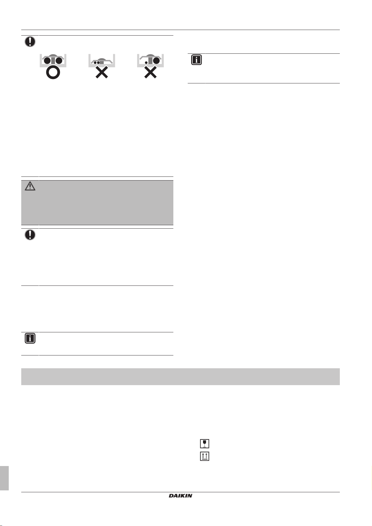
▪ When handling the unit, take into account the following:
Fragile, handle the unit with care.
Keep the unit upright in order to avoid damage.
▪ Prepare the path along which you want to bring the unit inside in
advance.
Installer and user reference guide
6
VAM350~2000J7VEB
Heat reclaim ventilation unit
4P487293-1 – 2017.08
3 About the box
2
1
3
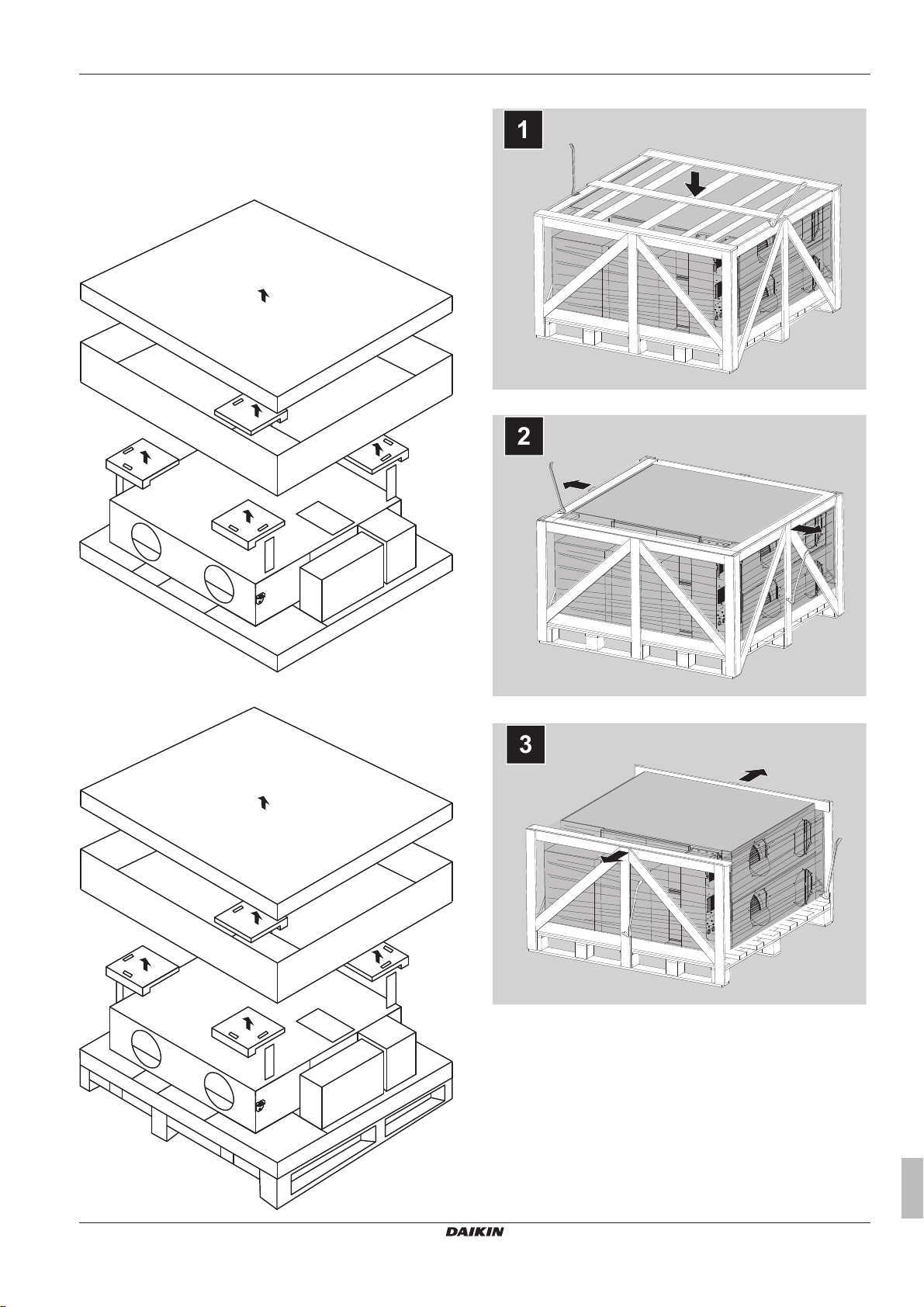
3.2 Heat reclaim ventilation unit
3.2.1 To unpack the heat reclaim ventilation unit
VAM350+VAM500
VAM1500+VAM2000
VAM650~1000
VAM350~2000J7VEB
Heat reclaim ventilation unit
4P487293-1 – 2017.08
Installer and user reference guide
7
3 About the box
dcba e
Name Plate
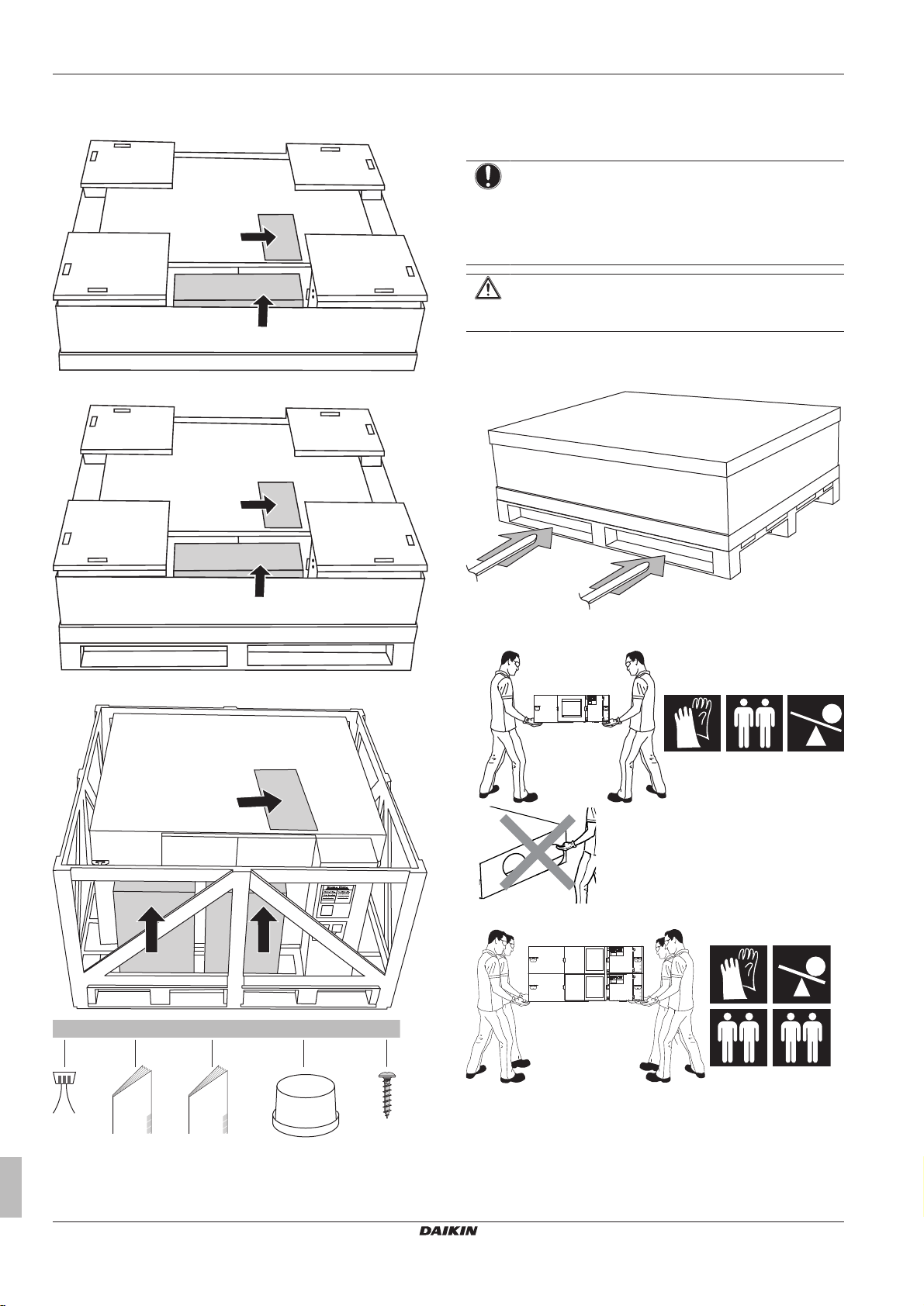
3.2.2 To remove the accessories
VAM350+VAM500
VAM650~1000
e Screws, VAM350+VAM500 16×, VAM650~1000 24×,
VAM1500+VAM2000 48×
3.2.3 To handle the heat reclaim ventilation unit
NOTICE
When removing the heat reclaim ventilation unit from the
packing, do NOT place the suction or discharge side of the
unit on the floor. Possible consequence: Deformation of
the suction or discharge openings and damaged expanded
polystyrene.
CAUTION
To avoid injury, do NOT touch the air inlet, the air outlet, or
the fans of the unit.
▪ With packing.
In case of VAM350+VAM500, do NOT use slings or a forklift.
In case of VAM650~2000, use a forklift.
VAM1500+VAM2000
▪ Without packing.
Carry VAM350~1000 slowly as shown:
Carry VAM1500+VAM2000 slowly as shown:
a Wire
b General safety precautions
c Installation and operation manual
d Duct joints, VAM350~1000 4×, VAM1500+VAM2000 8×
Installer and user reference guide
8
VAM350~2000J7VEB
Heat reclaim ventilation unit
4P487293-1 – 2017.08
4 About the units and options
Name Plate
4 About the units and options
4.1 Overview: About the units and options
This chapter contains information about:
▪ Identifying the unit
▪ Combining the unit with options
4.2 Identification
NOTICE
When installing or servicing several units at the same time,
make sure NOT to switch the service panels between
different models.
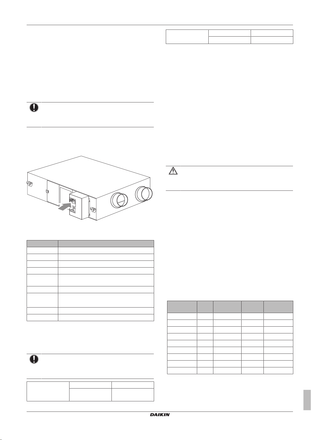
4.2.1 Identification label: Heat reclaim ventilation unit
Location
Model identification
Example: VAM500J7VEB[*]
Code Explanation
V Ventilation
A Air
M Mounted type
500 Nominal air flow rate (m³/h)
J Major design category (Design category for EC
7 Minor design category
VE Power supply: 1~, 50Hz 220~240V
B European market
[*] Minor model change indication
4.3 About the heat reclaim ventilation
The heat reclaim ventilation unit is intended for indoor installation.
NOTICE
ALWAYS use the air filter. If the air filter is NOT used, the
heat exchange elements can get clogged, possibly causing
poor performance and subsequent failure.
Operation range
Outdoor air + return
air
application)
Power supply: 1~, 60Hz 220V
unit
Temperature –10°CDB~46°CDB
Relative Humidity ≤80%
Operation range
Unit location
It is possible that, due to condensation, the paper heat exchanger
deteriorates when the unit operates in conditions with high indoor
humidity combined with low outdoor temperature. If such combined
conditions occur for an extended period of time, the necessary
precautions have to be taken to prevent condensation. Example:
install a pre-heater to heat up the outdoor air.
When the heat reclaim ventilation unit is installed upside down, the
minimum allowed outdoor air temperature is 5°C. If this CANNOT be
guaranteed, you MUST install a heater to heat up the outdoor air to
5°C.
Temperature 0°CDB~40°CDB
Relative Humidity ≤80%
4.4 Combining units and options
4.4.1 Possible options for the heat reclaim ventilation unit
Adapter printed circuit board
Options BRP4A50A and KRP2A51.
At temperatures below –10°C, it is mandatory to use an electrical
heater. This is connected with option PCB BRP4A50A.
CAUTION
If an electrical heater is installed, use nonflammable duct.
For safety, be sure to keep 2 m or more between the
heater and the heat reclaim ventilation unit.
If you install any of these options on the VAM650, you have to
prepare the mounting plate (EKMP65VAM).
If you install any of these options on the VAM1500 or VAM2000, you
have to prepare the mounting plate (EKMPVAM).
If you install KRP2A51, you have to prepare the fixing box
(KRP1BA101).
Filter
When. This option might be mandatory. Check the local legislation.
It is recommended in places with poor outside air quality.
Where. Install the filter behind the heat exchange element either at
the side of air supply or air exhaust. Keep the standard filter in place.
ONLY replace the standard filter when an option filter is put in front
of and behind the heat exchange element.
How. For installation instructions, see the installation manual of the
filter kit.
Pressure drop over the filter. See the databook for pressure drop
curves for each capacity class of unit and each class of filter.
Model Filter
EKAFVJ50F6 M6 ◯ — —
EKAFVJ50F7 F7 ◯ — —
EKAFVJ50F8 F8 ◯ — —
EKAFVJ65F6 M6 — ◯ —
EKAFVJ65F7 F7 — ◯ —
EKAFVJ65F8 F8 — ◯ —
EKAFVJ100F6 M6 — — ◯
EKAFVJ100F7 F7 — — ◯
EKAFVJ100F8 F8 — — ◯
Plenum (EKPLEN200)
When. The plenum is an option for VAM1500+VAM2000. This
option can be used to ease the installation of the heat reclaim
ventilation unit.
VAM350+500 VAM650 VAM800~2000
class
VAM350~2000J7VEB
Heat reclaim ventilation unit
4P487293-1 – 2017.08
Installer and user reference guide
9
5 Preparation
a
c
b
f
g
f
f
Where. Replace the 2 duct joints of Ø250mm with the plenum and a
duct joint of Ø350mm.
How. For installation instructions, see the installation manual of the
plenum kit.
CO2 sensor (BRYMA*)
When. The CO2 sensor is optional. This option can be used to have
a ventilation rate in function of the CO2 concentration.
Where. Install the CO2 sensor in the heat reclaim ventilation unit. For
VAM1500+VAM2000, install the CO2 sensor in the upper unit of the
heat reclaim ventilation unit.
How. For installation instructions, see "8.5.4 About the carbon
dioxide sensor"on page35.
5 Preparation
5.1 Overview: Preparation
This chapter describes what you have to do and know before going
on-site.
It contains information about:
▪ Preparing the installation site
▪ Preparing the unit
▪ Preparing the electrical wiring
▪ Preparing the installation of the ducts
CAUTION
▪ The appliance is designed to be a built-in appliance. It
must NOT be accessible to the general public.
Adequate measures have to be taken to prevent
access by other than qualified persons.
▪ Check if the installation location can support the unit's
weight. Poor installation is hazardous. It can also cause
vibrations or unusual operating noise.
▪ Provide sufficient service space and inspection holes.
Inspection holes are needed for the air filters, the heat
exchange elements and the fans.
▪ Do NOT install the unit so that it is in contact with a
ceiling or wall, this may cause vibration.
CAUTION
Appliance NOT accessible to the general public, install it in
a secured area, protected from easy access.
This unit is suitable for installation in a commercial and
light industrial environment.
For VAM800~2000
NOTICE
This is a class A product. In a domestic environment this
product may cause radio interference in which case the
user may be required to take adequate measures.
Service space
See "6.1Service space: Heat reclaim ventilation unit"on page13.
5.2 Preparing the installation site
Do NOT install the unit in places often used as work place. In case
of construction works (e.g. grinding works) where a lot of dust is
created, the unit MUST be covered.
Choose an installation location with sufficient space for carrying the
unit in and out of the site.
Do NOT install a heat reclaim ventilation unit or air suction/discharge
grille in the following places:
▪ Places, such as machinery plants and chemical plants, where
noxious gases or corrosive components of materials such as acid,
alkali, organic solvent and paint are present.
▪ Places, such as bathrooms, subject to moisture. Moisture can
cause electric shock, electric leakage and other failures.
▪ Places subject to high temperature or direct flames.
▪ Places subject to much carbon black. Carbon black attaches to air
filter and heat exchange elements, disabling them.
5.2.1 Installation site requirements for the heat reclaim ventilation unit
INFORMATION
Also read the general installation site requirements. See
the "General safety precautions" chapter.
5.3 Preparing the unit
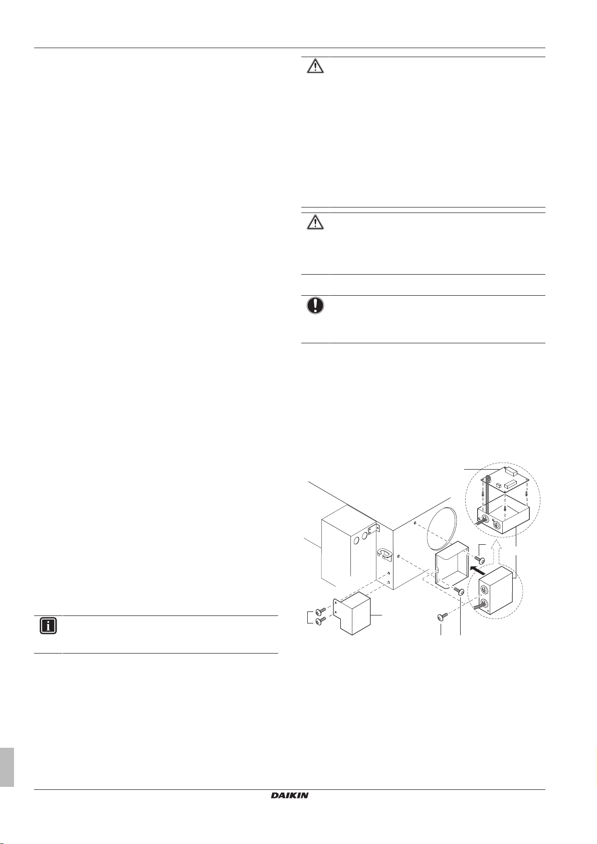
5.3.1 To install the optional adapter printed circuit board
For models 350-500-800-1000
a BRP4A50A (optional accessory)
b KRP2A51 (optional accessory)
c KRP1BA101 (Fixing box)
f Screw
g Screw (supplied with the fixing box)
1 Remove the screws from the unit.
2 Attach the optional adapter printed circuit board (KRP2A51) in
the fixing box (KRP1BA101).
3 Follow the installation instructions provided with the option kits
(BRP4A50A, KRP2A51 and KRP1BA101).
Installer and user reference guide
10
VAM350~2000J7VEB
Heat reclaim ventilation unit
4P487293-1 – 2017.08
5 Preparation
a d
c
b
g
f
f
f
a
e
f
f
f
g
b
b + c
c
1
2
4 Guide the circuit board wire through the dedicated holes and
attach it as instructed in "6.5.2 Opening the switch box" on
page16.
5 Attach the options to the unit, as shown in the figure.
6 After the wires are connected, fasten the switch box cover.
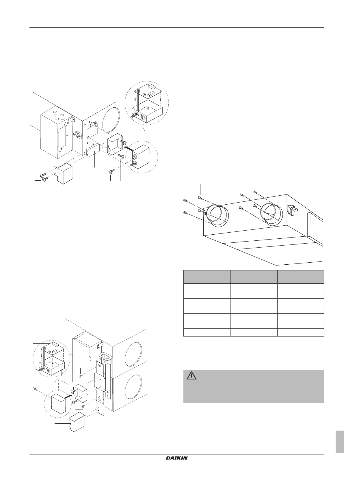
For model 650
a BRP4A50A (optional accessory)
b KRP2A51 (optional accessory)
c KRP1BA101 (Fixing box)
d EKMP65VAM (Mounting plate)
f Screw
g Screw (supplied with the fixing box)
1 Remove the screws from the unit.
2 Attach the optional mounting plate (EKMP65VAM) to the unit.
3 Attach the optional adapter printed circuit board (KRP2A51) in
the fixing box (KRP1BA101).
4 Follow the installation instructions provided with the option kits
(BRP4A50A, KRP2A51 and KRP1BA101).
5 Guide the circuit board wire through the dedicated holes and
attach it as instructed in "6.5.2 Opening the switch box" on
page16.
6 Attach the options to the optional mounting plate, as shown in
the figure.
7 After the wires are connected, fasten the switch box cover.
For models 1500+2000
e EKMPVAM (Mounting plate)
f Screw
g Screw (supplied with the fixing box)
1 Remove the screws that are in the middle of the casing fixing
plate.
2 Attach the optional mounting plate (EKMPVAM) on top of the
casing fixing plate.
3 Attach the optional adapter printed circuit board (KRP2A51) in
the fixing box (KRP1BA101).
4 Follow the installation instructions provided with the option kits
(BRP4A50A, KRP2A51 and KRP1BA101).
5 Guide the circuit board wire through the dedicated holes and
attach it as instructed in "6.5.2 Opening the switch box" on
page16.
6 Attach the options to the optional mounting plate, as shown in
the figure.
7 After the wires are connected, fasten the switch box cover.
5.3.2 To install the duct joints
1 Position the duct joints over the duct holes.
2 Secure the duct joints with the provided screws (accessories).
Models Number of provided
screws
VAM350 16 4× Ø200mm
VAM500 16 4× Ø200mm
VAM650 24 4× Ø250mm
VAM800 24 4× Ø250mm
VAM1000 24 4× Ø250mm
VAM1500 48 8× Ø250mm
VAM2000 48 8× Ø250mm
Number of provided
duct joints
VAM350~2000J7VEB
Heat reclaim ventilation unit
4P487293-1 – 2017.08
a BRP4A50A (optional accessory)
b KRP2A51 (optional accessory)
c KRP1BA101 (Fixing box)
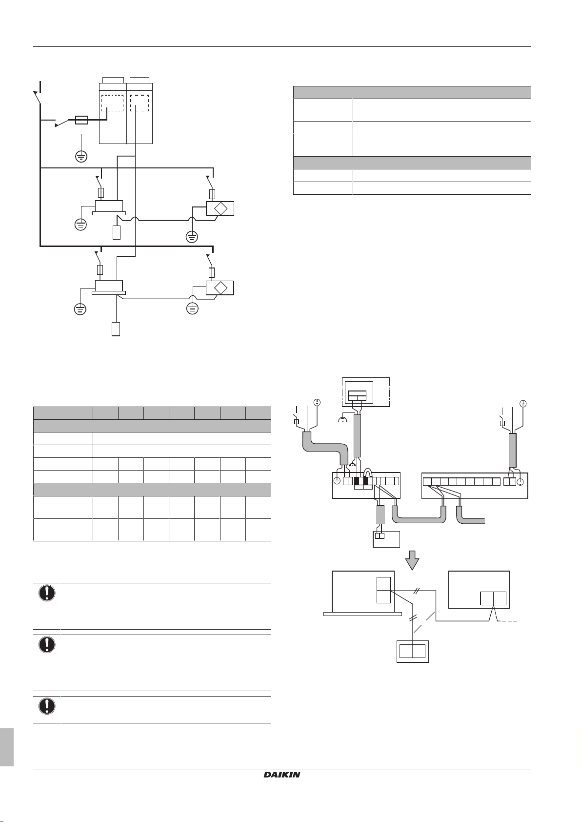
5.4 Preparing the electrical wiring
5.4.1 Wiring connection
WARNING
A main switch or other means for disconnection, having a
contact separation in all poles, MUST be incorporated in
the fixed wiring in accordance with the applicable
legislation.
You can use a single switch to supply power to units on the same
system. However, branch switches and branch circuit breakers
MUST be selected carefully.
Fit the power supply wiring of each unit with a switch and fuse as
shown in the drawing below.
Installer and user reference guide
11
5 Preparation
a
b
b
c
d
e
e
VRV
HRV
P1
P1
P1
P2
P2
P2
L
N
1 2
Out
VRV HRV
L
N
L N 1 12 2
P1 P2 F1 F1 T1 T1
P2 P1 F1 F2 J2 J3JC L NJ1
a
b
e
c
dd
g
f
f
Complete system example
a VRV outdoor unit
b VRV indoor unit
c Power supply
d Main switch
e User interface
5.4.3 Specifications for field supplied fuses and wires
Power supply wiring
Field supplied
fuses
Wire H05VV-U3G
Size Wire size MUST comply with the applicable
Transmission wiring
Wiring Shielded wire (2 wire)
Size 0.75~1.25mm²
Precautions
When connecting more than one wire to the power supply wiring,
use a 2mm² (Ø1.6mm) gauge wire.
When using 2 power wires of a gauge greater than 2 mm²
(Ø1.6mm), branch the line outside the terminal board of the unit, in
accordance with electrical equipment standards. The branch MUST
be sheathed to provide a degree of insulation equal to or greater
than the power supply wiring itself.
Keep the total current of crossover wiring between indoor units to
less than 12A.
Do NOT connect wires of different gauge to the same grounding
terminal. Loose connections may diminish the protection.
For the user interface wiring, refer to the installation manual of the
user interface delivered with the user interface.
Wiring example
16A
legislation.
5.4.2 Component electrical specifications
Model 350 500 650 800 1000 1500 2000
Power supply
50Hz 198~264V
60Hz 198~242V
MCA (A) 1.56 2.08 2.80 4.39 4.90 8.78 9.80
MFA (A) 16 16 16 16 16 16 16
Fan motor
P (kW) 0.08×20.08×20.106×20.21×20.21×20.21×40.21×
FLA (A) 0.62×20.83×21.12×21.76×21.96×21.76×41.96×
MCA Minimum Circuit Amps
NOTICE
MFA Maximum Fuse Amps
P Motor Rated Load
FLA Full Load Amps
When using residual current operated circuit breakers,
make sure to use a high speed type 300mA rated residual
operating current.
NOTICE
The power supply MUST be protected with the required
safety devices, i.e. a main switch, a slow blow fuse on
each phase and an earth leakage protector in accordance
with the applicable legislation.
Installer and user reference guide
12
NOTICE
See the engineering data book for details.
4
4
a Outdoor unit/BS unit
b Switch box
c Indoor unit
d Power supply 220-240V~50Hz
e User interface for VRV
f Transmission wiring
g User interface for heat reclaim ventilation unit
▪ All transmission wiring, except for the user interface wires, is
polarised and MUST match the terminal symbol.
VAM350~2000J7VEB
Heat reclaim ventilation unit
4P487293-1 – 2017.08
6 Installation
>50
a
>600
150-250
>1000
(mm)
▪ Use shielded cable for the transmission wiring. Ground the shield
of the shielded cable to at the grounding screw, with the C-cup
washer.
5.5 Preparing the installation of the ducts
INFORMATION
▪ Flexible ducting with sound insulation is effective to
reduce blowing noises.
▪ When you select installation materials, consider the
required volume of air flow and the acceptable level of
noise for that particular installation.
▪ When the return air infiltrates into the ceiling and the
temperature and humidity in the ceiling become too
high, insulate the metal parts of the unit.
▪ ONLY use the service hole to access the inside of the
unit.
▪ The sound pressure level is less than 70dBA.
CAUTION
▪ For safety reasons, the required minimum length of the
ducting is 1.5 m. If the ducting is shorter, or if no
ducting is installed, then you MUST install grilles in the
duct openings or the openings of the unit.
▪ Make sure no wind can blow in the ducting.
6 Installation
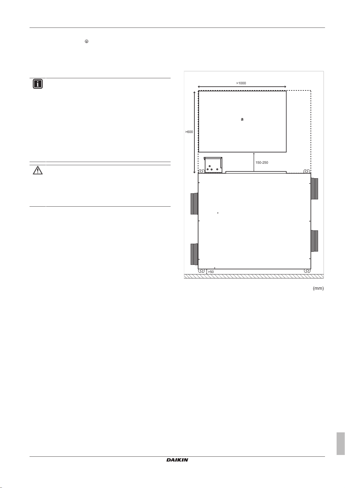
6.1 Service space: Heat reclaim ventilation unit
a Service space
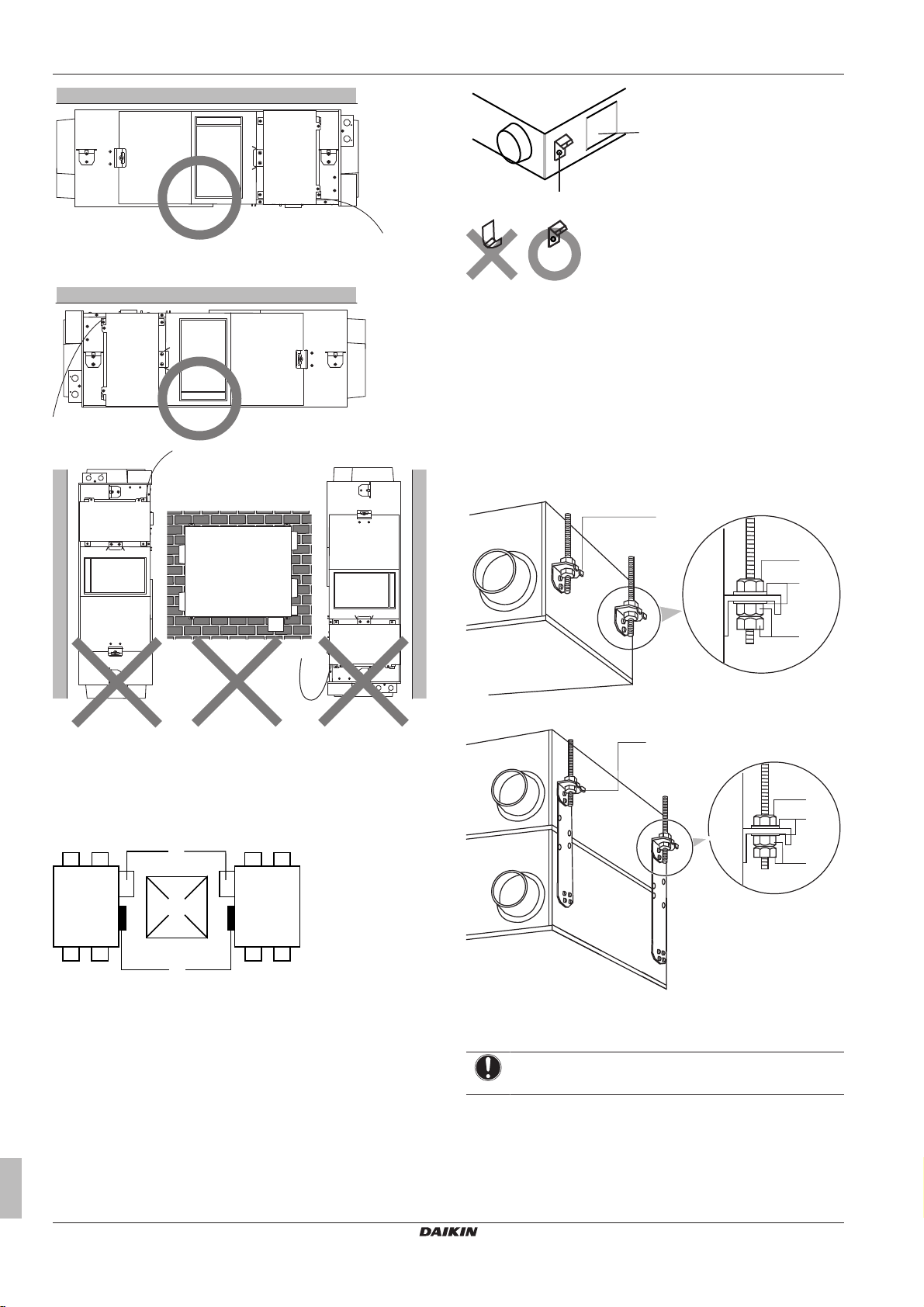
6.2 Unit orientation
The following illustration helps you to install the heat reclaim
ventilation unit in the correct position:
VAM350~2000J7VEB
Heat reclaim ventilation unit
4P487293-1 – 2017.08
Installer and user reference guide
13
6 Installation
a
b
c
b
a
a
c
b
d
a
c
b
d
a Ceiling hook
b Maintenance cover
6.3 To install the anchor bolts
Prerequisite: Before you install the anchor bolt, check if foreign
objects such as vinyl and paper are still inside the fan housing. If so,
remove them.
1 Install the anchor bolt (M10 to M12).
2 Pass the metal suspension bracket through the anchor bolt.
3 Secure the anchor bolt with washer and nut.
For VAM350~1000:
Installation tips:
▪ Installing the unit upside down allows for common use of the
inspection hole, reducing the required maintenance space. For
example, if 2 units are installed closely together, ONLY 1
inspection hole is required for maintaining or replacing filters, heat
exchange elements,…
a Control box
b Maintenance cover
c Inspection hole
▪ When the heat reclaim ventilation unit is installed upside down,
the minimum allowed outdoor air temperature is 5°C. If this
CANNOT be guaranteed, you MUST install a heater to heat up the
outdoor air to 5°C.
▪ Keep in mind that the ceiling hooks have to be reinstalled when
the heat reclaim ventilation unit is installed upside down. They
have to be rotated 180°, so that they are upside down (see the
illustration).
For VAM1500+VAM2000:
a Ceiling hook
b Nut
c Washer
d Double nuts
NOTICE
Always hang up the unit by its suspension brackets.
6.4 Duct connections
Do NOT connect the ducts as follows:
Installer and user reference guide
14
VAM350~2000J7VEB
Heat reclaim ventilation unit
4P487293-1 – 2017.08
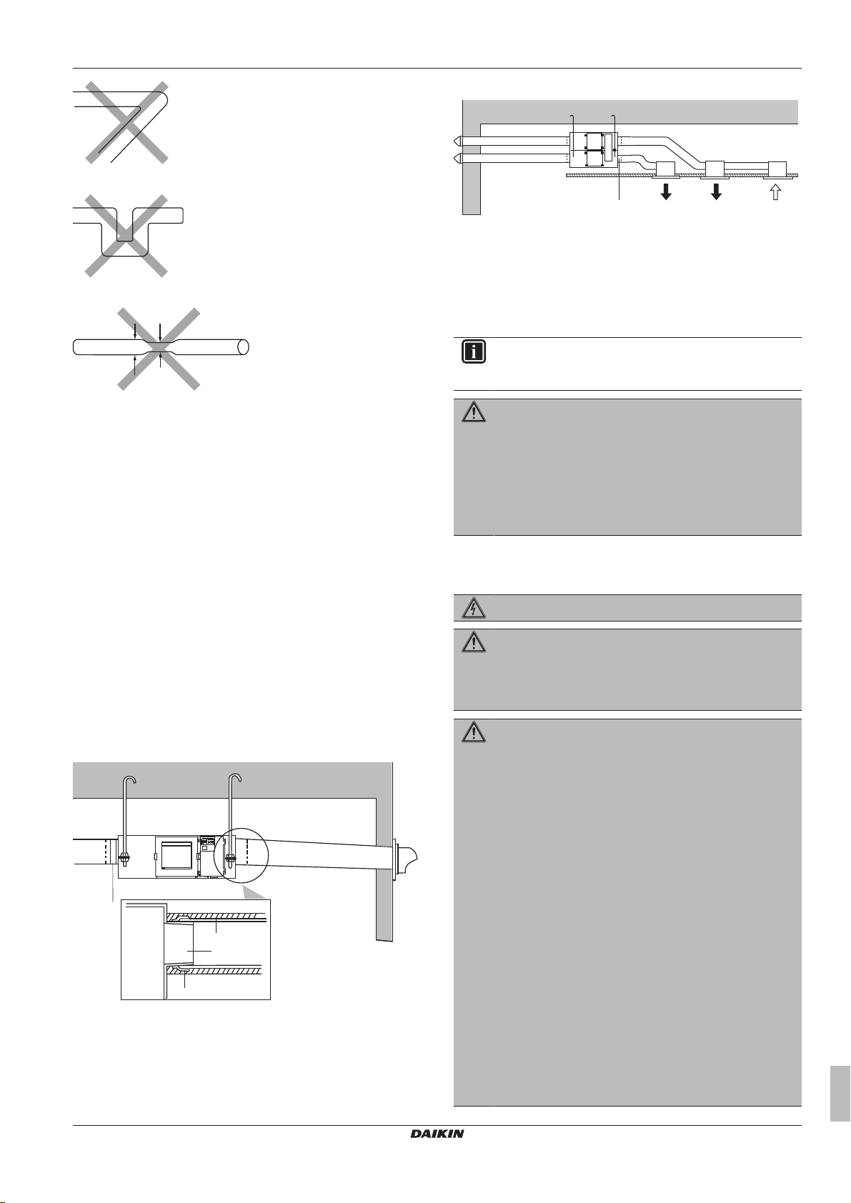
Extreme bend. Do NOT bend the duct over 90°.
b
c
a
d
a
Name Plate
d
c
e e
f
Multi bend
6 Installation
VAM1500+VAM2000
a Aluminium tape (field supply)
b Insulation material (field supply)
c Duct joint (accessories)
d Slope over 1/50
e Supply air
f Return air
6.5 Electrical wiring
INFORMATION
Also read the precautions and requirements in the
"General safety precautions" chapter.
Reduced diameter. Do NOT reduce the duct diameter.
▪ The minimum bend radius for flexible ducts is as follows:
(Øduct/2)×1.5
▪ To prevent air leakage, wind aluminium tape around the section
where the duct joints and the ducts are connected.
▪ Install the opening of the supply air as far as possible from the
opening of the return air.
▪ Use ducts with a diameter that fit the unit model. See the data
book.
▪ Install the two outdoor ducts with down slope (slope ratio of 1 in
50 or more) to prevent entry of rain water. Also provide insulation
for both ducts, to prevent dew formation. (Material: 25 mm thick
glass wool)
▪ If the level of temperature and humidity inside the ceiling is always
high, install ventilation inside the ceiling.
▪ Insulate the duct and the wall electrically when a metal duct has to
penetrate the metal lattice and wire lattice or the metal lining of a
wooden structure wall.
▪ Install the ducts in a manner that the wind CANNOT blow inside
the ducting.
VAM350~1000
WARNING
▪ All wiring MUST be performed by an authorised
electrician and MUST comply with the applicable
legislation.
▪ Make electrical connections to the fixed wiring.
▪ All components procured on the site and all electrical
construction MUST comply with the applicable
legislation.
6.5.1 Precautions when connecting electrical wiring
DANGER: RISK OF ELECTROCUTION
WARNING
If NOT factory installed, a main switch or other means for
disconnection, having a contact separation in all poles
providing full disconnection under overvoltage category III
condition, MUST be installed in the fixed wiring.
WARNING
▪ ONLY use copper wires.
▪ Make sure the field wiring complies with the applicable
legislation.
▪ All field wiring MUST be performed in accordance with
the wiring diagram supplied with the product.
▪ NEVER squeeze bundled cables and make sure they
do NOT come in contact with the piping and sharp
edges. Make sure no external pressure is applied to the
terminal connections.
▪ Make sure to install earth wiring. Do NOT earth the unit
to a utility pipe, surge absorber, or telephone earth.
Incomplete earth may cause electrical shock.
▪ Make sure to use a dedicated power circuit. NEVER
use a power supply shared by another appliance.
▪ Make sure to install the required fuses or circuit
breakers.
▪ Make sure to install an earth leakage protector. Failure
to do so may cause electric shock or fire.
▪ When installing the earth leakage protector, make sure
it is compatible with the inverter (resistant to high
frequency electric noise) to avoid unnecessary opening
of the earth leakage protector.
VAM350~2000J7VEB
Heat reclaim ventilation unit
4P487293-1 – 2017.08
Installer and user reference guide
15
 Loading...