

Daikin FTXS36LVJU, RKS36LVJU, RKS30LVJU, FDXS09LVJU, FTXS12LVJU Service Manual
...
Service
Manual
Inverter Pair
FTXS-L Series
FDXS-L Series
SiUS091133
[Applied Models]
Inverter Pair : Cooling Only
Inverter Pair : Heat Pump

Cooling Only
Indoor Unit
FTXS30LVJU
FTXS36LVJU
Outdoor Unit
RKS30LVJU
RKS36LVJU
SiUS091133
Inverter Pair
FTXS-L Series
FDXS-L Series
Heat Pump
Indoor Unit
FTXS09LVJU FDXS09LVJU
FTXS12LVJU FDXS12LVJU
FTXS15LVJU
FTXS18LVJU
FTXS24LVJU
FTXS30LVJU
FTXS36LVJU
Outdoor Unit
RXS09LVJU
RXS12LVJU
RXS15LVJU
RXS18LVJU
RXS24LVJU
RXS30LVJU
RXS36LVJU
Table of Contents i

SiUS091133
Part 1
Part 2
1. Safety Considerations..................................................................................i
1.1 Safety Considerations for Repair .................................................................. i
1.2 Safety Considerations for Users....................................................................ii
List of Functions ...................................................................1
1. Functions.....................................................................................................2
1.1 FTXS Series................................................................... ..............................2
1.2 FDXS Series.................................................................................................4
Specifications .......................................................................5
1. Specifications..............................................................................................6
1.1 FTXS Series................................................................... ..............................6
1.2 FDXS Series...............................................................................................11
Part 3
Part 4
Printed Circuit Board
Connector Wiring Diagram..................................................12
1. Indoor Unit.................................................................................................13
1.1 FTXS09/12LVJU ........................................................................................13
1.2 FTXS15/18/24/30/36LVJU .........................................................................16
1.3 FDXS09/12LVJU........................................................................................ 19
2. Outdoor Unit..............................................................................................21
2.1 RXS09/12LVJU..........................................................................................21
2.2 RXS15/18LVJU..........................................................................................23
2.3 RXS24LVJU, RK(X)S30/36LVJU............................................................... 25
Function and Control...........................................................27
1. Main Functions..........................................................................................28
1.1 Temperature Control..................................................................................28
1.2 Frequency Principle....................................................................................28
1.3 Airflow Direction Control (FTXS Series).....................................................30
1.4 Fan Speed Control for Indoor Unit .............................................................32
1.5 Program Dry Operation.............................................................................. 33
1.6 Automatic Operation...................................................................................34
1.7 Thermostat Control.....................................................................................35
1.8 NIGHT SET Mode......................................................................................36
1.9 ECONO Operation .....................................................................................37
1.10 INTELLIGENT EYE Operation (FTXS Series)........................................... 38
1.11 Inverter POWERFUL Operation.................................................................39
ii Table of Contents

Part 5
SiUS091133
1.12 Other Functions..........................................................................................40
2. Function of Thermistor..............................................................................41
3. Control Specification. ................................................................................42
3.1 Mode Hierarchy..........................................................................................42
3.2 Frequency Control......................................................................................43
3.3 Controls at Mode Changing / Start-up........................................................45
3.4 Discharge Pipe Temperature Control.........................................................46
3.5 Input Current Control..................................................................................47
3.6 Freeze-up Protection Control.....................................................................48
3.7 Heating Peak-cut Control........................................................................... 48
3.8 Outdoor Fan Control...................................................................................49
3.9 Liquid Compression Protection Function....................................................49
3.10 Defrost Control...........................................................................................50
3.11 Electronic Expansion Valve Control...........................................................51
3.12 Malfunctions............................................................................................... 54
Operation Manual................................................................55
1. System Configuration................................................................................56
2. FTXS Series..............................................................................................57
2.1 Remote Controller......................................................................................57
2.2 AUTO · DRY · COOL · HEAT · FAN Operation..........................................59
2.3 Adjusting the Airflow Direction and Rate.................................................... 61
2.4 COMFORT AIRFLOW / INTELLIGENT EYE Operation............................. 64
2.5 POWERFUL Operation.............................................................................. 66
2.6 OUTDOOR UNIT QUIET Operation...........................................................67
2.7 ECONO Operation .....................................................................................68
2.8 OFF TIMER Operation...............................................................................69
2.9 ON TIMER Operation.................................................................................70
2.10 WEEKLY TIMER Operation....................................................................... 71
3. FDXS Series .............................................................................................77
3.1 Remote Controller......................................................................................77
3.2 AUTO · DRY · COOL · HEAT · FAN Operation..........................................79
3.3 Adjusting the Airflow Rate..........................................................................81
3.4 POWERFUL Operation.............................................................................. 82
3.5 OUTDOOR UNIT QUIET Operation...........................................................83
3.6 ECONO Operation .....................................................................................84
3.7 OFF TIMER Operation...............................................................................85
3.8 ON TIMER Operation.................................................................................86
Part 6
Service Diagnosis................................................................87
1. Troubleshooting with LED.........................................................................89
1.1 Indoor Unit..................................................................................................89
1.2 Outdoor Unit...............................................................................................89
Table of Contents iii

SiUS091133
2. Problem Symptoms and Measures...........................................................90
3. Service Check Function............................................................................91
4. Troubleshooting ........................................................................................94
4.1 Error Codes and Description......................................................................94
4.2 Indoor Unit PCB Abnormality .....................................................................95
4.3 Freeze-up Protection Control or Heating Peak-cut Control........................ 97
4.4 Fan Motor or Related Abnormality .............................................................99
4.5 Thermistor or Related Abnormality (Indoor Unit)......................................103
4.6 Refrigerant Shortage................................................................................104
4.7 Low-voltage Detection or Over-voltage Detection....................................107
4.8 Signal Transmission Error (between Indoor Unit and Outdoor Unit)........ 109
4.9 Signal Transmission Error on Outdoor Unit PCB
(24/30/36 Class Only)111
4.10 Unspecified Voltage (between Indoor Unit and Outdoor Unit) .................112
4.11 Outdoor Unit PCB Abnormality.................................................................113
4.12 OL Activation (Compressor Overload)..................................................... 115
4.13 Compressor Lock.....................................................................................116
4.14 DC Fan Lock............................................................................................ 117
4.15 Input Overcurrent Detection.....................................................................118
4.16 Four-Way Valve Abnormality....................................................................119
4.17 Discharge Pipe Temperature Control....................................................... 121
4.18 High Pressure Control in Cooling............................................................. 123
4.19 Compressor System Sensor Abnormality ................................................ 125
4.20 Position Sensor Abnormality....................................................................128
4.21 DC Voltage / Current Sensor Abnormality (09/12 Class Only)................. 131
4.22 CT or Related Abnormality (24/30/36 Class Only)................................... 132
4.23 Thermistor or Related Abnormality (Outdoor Unit)................................... 134
4.24 Electrical Box Temperature Rise.............................................................. 136
4.25 Radiation Fin Temperature Rise.............................................................. 138
4.26 Output Overcurrent Detection.................................................................. 140
5. Check......................................................................................................142
5.1 Thermistor Resistance Check.................................................................. 142
5.2 Fan Motor Connector Output Check ........................................................143
5.3 Hall IC Check ...........................................................................................143
5.4 Power Supply Waveforms Check.............................................................144
5.5 Electronic Expansion Valve Check........................................................... 144
5.6 Four-Way Valve Performance Check.......................................................145
5.7 Inverter Units Refrigerant System Check.................................................145
5.8 “Inverter Checker” Check.........................................................................146
5.9 Rotation Pulse Check on the Outdoor Unit PCB...................................... 148
5.10 Installation Condition Check..................................................................... 149
5.11 Discharge Pressure Check.......................................................................150
5.12 Outdoor Fan System Check.....................................................................150
5.13 Main Circuit Short Check..........................................................................151
5.14 Capacitor Voltage Check.......................................................................... 152
5.15 Power Module Check...............................................................................153
iv Table of Contents

Part 7
SiUS091133
Removal Procedure...........................................................155
1. Indoor Unit: FTXS09/12LVJU..................................................................157
1.1 Removal of Air Filters...............................................................................157
1.2 Removal of Front Panel............................................................................159
1.3 Removal of Front Grille ............................................................................160
1.4 Removal of Horizontal Blades / Vertical Blades....................................... 162
1.5 Removal of Electrical Box ........................................................................166
1.6 Removal of PCBs.....................................................................................170
1.7 Removal of Swing Motors ........................................................................176
1.8 Removal of Indoor Heat Exchanger.........................................................180
1.9 Removal of Fan Motor..............................................................................183
2. Indoor Unit: FTXS15/18/24LVJU.............................................................186
2.1 Removal of Air Filters / Front Panel .........................................................186
2.2 Removal of Front Grille ............................................................................189
2.3 Removal of Electrical Box ........................................................................192
2.4 Removal of PCBs.....................................................................................196
2.5 Removal of Horizontal Blades / Swing Motors.........................................205
2.6 Removal of Indoor Heat Exchanger.........................................................213
2.7 Removal of Fan Motor / Fan Rotor...........................................................217
2.8 Removal of Vertical Blade ASSYs............................................................ 220
3. Indoor Unit: FTXS30/36LVJU..................................................................221
3.1 Removal of Air Filters / Front Panel .........................................................221
3.2 Removal of Front Grille ............................................................................224
3.3 Removal of Electrical Box ........................................................................228
3.4 Removal of PCBs.....................................................................................232
3.5 Removal of Horizontal Blades / Swing Motors.........................................241
3.6 Removal of Fan Motor..............................................................................250
3.7 Removal of Indoor Heat Exchanger.........................................................254
3.8 Removal of Fan Rotor..............................................................................258
3.9 Removal of Vertical Blade ASSYs............................................................ 260
4. Outdoor Unit: RXS09/12LVJU.................................................................261
4.1 Removal of Outer Panels / Fan Motor......................................................261
4.2 Removal of Electrical Box ........................................................................270
4.3 Removal of PCBs.....................................................................................273
4.4 Removal of Reactor / Partition Plate........................................................ 281
4.5 Removal of Sound Blankets..................................................................... 283
4.6 Removal of Four-Way Valve ....................................................................285
4.7 Removal of Compressor...........................................................................288
5. Outdoor Unit: RXS15/18LVJU.................................................................290
5.1 Removal of Outer Panels.........................................................................290
5.2 Removal of Outdoor Fan / Fan Motor.......................................................293
5.3 Removal of Electrical Box ........................................................................297
5.4 Removal of PCBs.....................................................................................308
5.5 Removal of Sound Blankets / Thermistors............................................... 316
5.6 Removal of Four-Way Valve ....................................................................320
Table of Contents v

SiUS091133
5.7 Removal of Electronic Expansion Valve...................................................321
5.8 Removal of Compressor...........................................................................323
6. Outdoor Unit: RXS24LVJU......................................................................326
6.1 Removal of Outer Panels.........................................................................326
6.2 Removal of Electrical Box ........................................................................340
6.3 Removal of PCBs.....................................................................................344
6.4 Removal of Fan Motor..............................................................................347
6.5 Removal of Coils / Thermistors................................................................ 348
6.6 Removal of Sound Blankets..................................................................... 351
6.7 Removal of Compressor...........................................................................354
7. Outdoor Unit: RKS30/36LVJU, RXS30/36LVJU .....................................356
7.1 Removal of Outer Panels.........................................................................356
7.2 Removal of Electrical Box ........................................................................367
7.3 Removal of PCBs.....................................................................................371
7.4 Removal of Fan Motor..............................................................................374
7.5 Removal of Coils / Thermistors................................................................ 375
7.6 Removal of Sound Blankets..................................................................... 378
7.7 Removal of Compressor...........................................................................380
Part 8
Part 9
Trial Operation and
Field Settings ....................................................................382
1. Pump Down Operation............................................................................383
2. Forced Cooling Operation.......................................................................384
3. Trial Operation ........................................................................................386
4. Field Settings ..........................................................................................387
4.1 Model Type Setting ..................................................................................387
4.2 Temperature Display Switch ....................................................................387
4.3 When 2 Units are Installed in 1 Room......................................................388
4.4 Facility Setting Jumper and Switch (Cooling at Low Outdoor
Temperature)............................................................................................389
4.5 Jumper Settings .......................................................................................390
5. Application of Silicon Grease to a Power Transistor and a Diode Bridge391
Appendix............................................................................392
1. Piping Diagrams......................................................................................393
1.1 Indoor unit ................................................................................................393
1.2 Outdoor Unit.............................................................................................396
2. Wiring Diagrams......................................................................................399
2.1 Indoor Unit................................................................................................399
2.2 Outdoor Unit.............................................................................................401
vi Table of Contents

SiUS091133
Table of Contents vii

Safety Considerations SiUS091133
1. Safety Considerations
Read these SAFETY CONSIDERAT IONS carefully before perf orming any repair work. Comply with these safety symbols without
fail.Meanings of DANGER, WARNING, CAUTION, and NOTE Symbols:
DANGER .............. Indicates an imminently hazardous situation which, if not avoided, will result in death or serious injury.
WARNING ............ Indicates a potentially hazardous situation which, if not avoided, could result in death or serious injury.
CAUTION ............. Indicates a potentially hazardous situation which, if not avoided, may result in minor or moderate injury. It
may also be used to alert against unsafe practices.
NOTE .................. Indicates situations that may result in equipment or property-damage accidents only.
1.1 Safety Considerations for Repair
• If refrigerant gas leaks during repair or service, ventilate the area immediately. Refrigerant gas may produce toxic gas if
it comes into contact with flames. Refrigerant g as is hea vier than ai r and replaces o xygen. In the event of an accident, a
massive leak could lead to oxygen depletion, especially in basements, and an asphyxiation hazard could occur leading
to serious injury or death.
• Do not start or stop the air conditioner operation by plugging or unplugging the power cable plug if a plug is used.
Plugging or unplugging the power cable plug to operate the equipment may cause an electrical shock or fire.
• Use parts listed in the service parts list and appropriate tools to conduct repair work. The use of inappropriate parts
or tools may cause an electrical shock or fire.
• Disconnect power before disassembling the equipment for repairs. Working on the equipment that is connected to
the power supply may cause an electric shock. If it is necessary to supply power to the equipment to conduct repairs
or to inspect the circuits, do not touch any electrically charged sections of the equipment.
• The step-up capacitor supplies high-voltage electricity to the electrical components of the outdoor unit. Discharge
the capacitor completely before conducting repair work. A charged capacitor may cause an electrical shock.
• If refrigerant gas is discharged during repair work, do not touch the discharged refrigerant gas. The refrigerant gas
may cause frost bite.
• Use only pipes, flare nuts, tools, and other materials designed specifically for R410A refrigerant systems. Never use
tools or materials designed for R22 refrigerant systems on an R410A refrigerant system. Doing so can cause a
serious accident or an equipment failure.
• Check to see if the parts and wires are mounted and connected properly, and if the connections at the soldered or
crimped terminals are secure. Improper installation and connections may cause excessive heat generation, fire, or
electrical shock.
• Prior to disconnecting the suction or discharge pipe from the compressor at the welded section, pump-down the
refrigerant gas completely in a well-ventilated place first. If there is refrigerant gas or oil remaining inside the
compressor, the refrigerant gas or oil can discharge when the pipe is being disconnected and it may cause an injury.
• Wear a safety helmet, gloves, and a safety belt when working at an elevated height of more than 6.5 ft (2 m). Insufficient
safety measures may cause a fall resulting in injury.
• Do not mix air or gas other than the specified refrigerant R410A to the refrigerant system. If air enters the refrigerant
systems, it can cause an excessive high pressure resulting in equipment damage and injury.
• When relocating the equipment, check if th e new installation site has sufficient strength to withstand the weight of the
equipment. If the installation site does not have sufficient strength and the equipment is not properly secured, the
equipment may fall and cause injury.
• Securely fasten the outside unit terminal cover (panel). If the terminal cover/panel is not fastened properly, dust or
water may enter the outside unit causing fire or electric shock.
• When relocating the system, keep the refrigerant circuit free from substances other than the specified refrigerant (R410A) such as air. Any presence of air or other foreign substance in the refrigerant circuit can cause an abnormal
pressure rise or rupture, resulting in injury.
• If refrigerant gas leaks, locate the leaking point and repair it before charging refrigerant. After charging refrigerant,
check for refrigerant leaks. If the leaking point cannot be located and the repair work must be stopped, perform a
pump-down and close the service valve to prevent the refrigerant gas from leaking into the room. The refrigerant gas
itself is harmless, but it may generate toxic gases if it comes into contact with flames.
viii

SiUS091133 Safety Considerations
• Do not repair the electrical components with wet hands. Working on the equipment with wet hands may cause an
electrical shock.
• Do not clean the air conditioner by splashing water on it. Washing the unit with water may cause an electrical shock.
• Ground the unit when repairing equipment in a humid or wet place to avoid electrical shocks.
• Turn off the power when cleaning the equipment to prevent internal fans that rotate at high speed from starting
suddenly as they can cause injury.
• Let the refrigerant lines cool down before performing any repair work. W orki ng on the unit when the refrigerant lines
are hot may cause burns.
• All welding and cutting operations m ust be done in a well-ventilated p lace to prevent th e accumulation of toxic f umes
or possibly oxygen deficiency to occur.
• Check the grounding and repair it if the equipment is not properly grounded. Improper grounding may cause an
electrical shock.
• Measure the insulation resistance after the repair. The resistance must be 1M or higher. Faulty insulation may
cause an electrical shock.
• Check the drainage of the indoor unit after finishing repair work. Faulty drainage may cause water to enter the room
resulting in wet floors and furniture.
• Do not tilt the unit when removing it. The water inside the unit may spill resulting in wet floors and furniture.
• Dismantling of the unit, disposal of the refrigerant, oil, and additional parts, should be done in accordance with the
relevant local, state, and national regulations.
1.2 Safety Considerations for Users
• Never attempt to modify the equipment. Doing so can cause electrical shock, excessive heat generation, or fire.
• If the power cable and lead wires have scratches or have become deteriorated, have them replaced. Damaged cable
and wires may cause an electrical shock or fire.
• Do not use a joined power cable or an extension cord, or share the same power outlet with other electrical appliances
as it may cause an electrical shock or fire.
• Use an exclusive power circuit for the equipment. Insufficient circuit amperage capacity may cause an electrical
shock or fire.
• Do not damage or modify the power cable. Damaged or modified power cables ma y cause an electrical s hoc k or fire.
Placing heavy items on the power cable or pulling the power cable may damage the cable.
• Check the unit foundation for damage on a continual basis, especially if it has been in use for a long time. If left in a
damaged condition, the unit may fall and cause injury. If the installation platform or frame has corroded, have it
replaced. A corroded platform or frame may cause the unit to fall resulting in injury.
• If the unit has a power cable plug and it is dirty, clean the p lu g before securely inserting it into a power outlet. If the
plug has a loose connection, tighten it or it may cause electrical shock or fire.
• After replacing the battery in the remote contro ller, dispose of th e old battery to pre vent ch ildren fr om s wallo wing it.
If a child swallows the battery, see a doctor immediately.
• Never remove the fan guard of the unit. A fan rotating at high speed without the fan guard is very dangerous.
• Before cleaning the unit, stop the operation of the unit by turning the power off or by pulling the power cable plug out
from its receptacle. Otherwise an electrical shock or injury may result.
• Do not wipe the controller operation pan el with be nzene, thinner, chemical du st cloth, etc. The panel may get
discolored or the coating can peel off. If it is extremely dirty , soak a cloth in a water-diluted neutral detergent, squeeze
it well, and wipe the panel clean. Then wipe it with another dry cloth.
ix

SiUS091133
Part 1
List of Functions
1. Functions.....................................................................................................2
1.1 FTXS Series................................................................... ..............................2
1.2 FDXS Series.................................................................................................4
1 List of Functions
SiUS091133 Functions
1. Functions
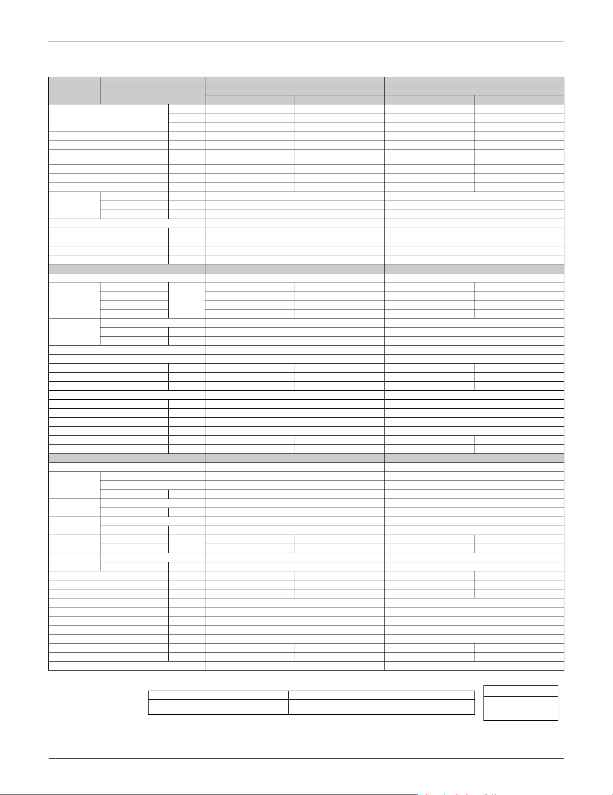
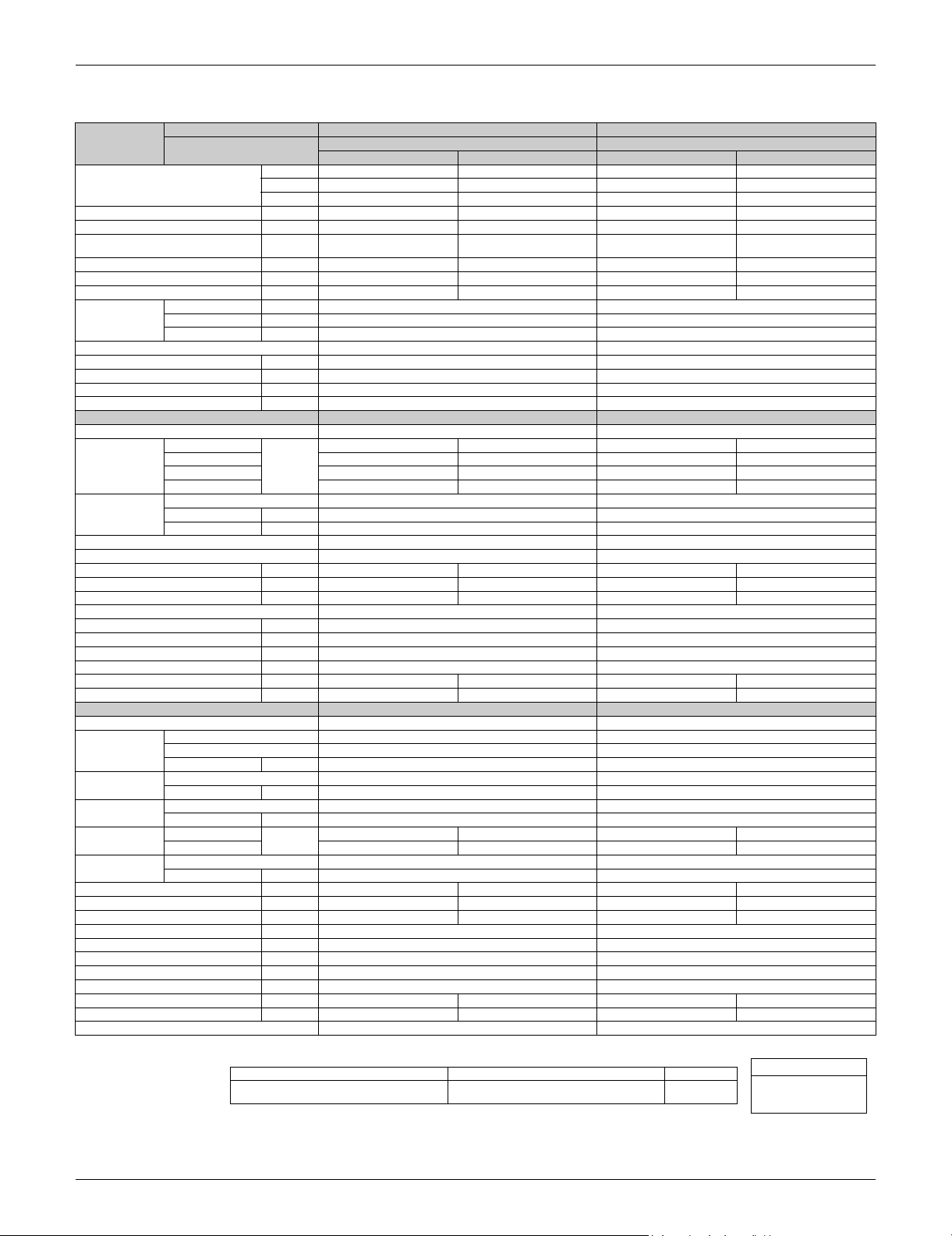
1.1 FTXS Series
Category Functions
FTXS09/12/15/18LVJU
RXS09/12/15/18LVJU
Basic
Function
Compressor Oval Scroll Compressor — —
Comfortable
Airflow
Comfort
Control
Operation Automatic Operation
Lifestyle
Convenience
Inverter (with Inverter Power Control) Health &
Operation Limit for Cooling (°FDB)
Operation Limit for Heating (°FWB)
PAM Control
Swing Compressor Air Filter (Prefilter)
Rotary Compressor — — Wipe-clean Flat Panel
Reluctance DC Motor Washable Grille — —
Power-Airflow Louver (Horizontal
Blade)
Power-Airflow Dual Louvers Good-Sleep Cooling Operation — —
Power-Airflow Diffuser — — Timer WEEKLY TIMER Operation
Wide-Angle Fins (Vertical Blades) 24-Hour ON/OFF TIMER
Vertical Auto-Swing (Up and Down) NIGHT SET Mode
Horizontal Auto-Swing (Right and Left) Worry Free
3-D Airflow Self-Diagnosis (Digital, LED) Display
COMFORT AIRFLOW Operation Wiring Error Check Function — —
Auto Fan Speed
Indoor Unit Quiet Operation
NIGHT QUIET Mode (Automatic) — — Flexibility Multi-Split / Split Type Compatible
OUTDOOR UNIT QUIET Operation
(Manual)
INTELLIGENT EYE Operation Flexible Power Supply Correspondence — —
Quick Warming Function Chargeless 32.8 ft 32.8 ft
Hot-Start Function Either Side Drain (Right or Left)
Automatic Defrosting Power Selection — —
Program Dry Function
Fan Only Remote
New POWERFUL Operation
(Non-Inverter)
Inverter POWERFUL Operation
Priority-Room Setting — —
COOL / HEAT Mode Lock — — DIII-NET Compatible (Adaptor) (Option)
HOME LEAVE Operation — — Remote
ECONO Operation Wired (Option)
Indoor Unit [ON/OFF] Button
Signal Receiving Sign
R/C with Back Light
Temperature Display — —
14 ~
114.8
5 ~
64.4
14 ~
114.8
5 ~
64.4
——
Low Temperature Cooling Operation
——
Note: : Holding Functions
— : No Functions
Category Functions
FTXS24LVJU
RXS24LVJU
Clean
“Reliability &
Durability”
Control
Controller
Air-Purifying Filter — —
Photocatalytic Deodorizing Filter — —
Air-Purifying Filter with Photocatalytic
Deodorizing Function
Titanium Apatite Photocatalytic
Air-Purifying Filter
MOLD PROOF Operation — —
Heating Dry Operation — —
Auto-Restart (after Power Failure)
Anticorrosion Treatment of Outdoor
Heat Exchanger
Indoor Unit
H/P, C/O Compatible Indoor Unit — —
°F/°C Changeover R/C Temperature
Display (factory setting: °F)
5-Room Centralized Controller (Option)
Remote Control Adaptor
(Normal Open-Pulse Contact) (Option)
Remote Control Adaptor
(Normal Open Contact) (Option)
Wireless
FTXS09/12/15/18LVJU
RXS09/12/15/18LVJU
FTXS24LVJU
RXS24LVJU
——
—
List of Functions 2

Functions SiUS091133
Category Functions
FTXS30/36LVJU
RKS30/36LVJU
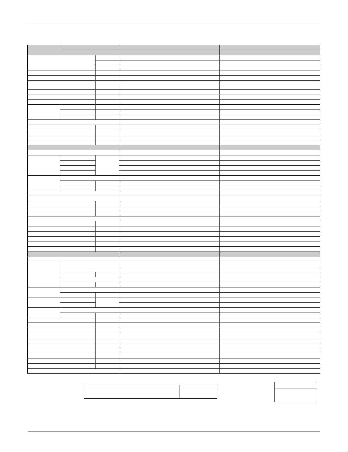
Basic
Function
Compressor Oval Scroll Compressor — — Air Filter (Prefilter)
Comfortable
Airflow
Comfort
Control
Operation
Lifestyle
Convenience
Inverter (with Inverter Power Control) Health &
Operation Limit for Cooling (°FDB)
Operation Limit for Heating (°FWB) —
PAM Control
Swing Compressor Wipe-Clean Flat Panel
Rotary Compressor — — Washable Grille — —
Reluctance DC Motor MOLD PROOF Operation — —
Power-Airflow Louver (Horizontal
Blade)
Power-Airflow Dual Louvers Good-Sleep Cooling Operation — —
Power-Airflow Diffuser — — Timer WEEKLY TIMER
Wide-Angle Fins (Vertical Blades) 24-Hour ON/OFF TIMER
Vertical Auto-Swing (Up and Down) NIGHT SET Mode
Horizontal Auto-Swing (Right and Left) Worry
3-D Airflow Self-Diagnosis (Digital, LED) Display
COMFORT AIRFLOW Operation Wiring Error Check Function — —
Auto Fan Speed
Indoor Unit Quiet Operation Flexibility Multi-Split / Split Type Compatible Indoor Unit — —
NIGHT QUIET Mode (Automatic) — — H/P, C/O Compatible Indoor Unit
OUTDOOR UNIT QUIET Operation
(Manual)
INTELLIGENT EYE Operation Chargeless
Quick Warming Function
(Preheating Operation)
Hot-Start Function — Power Selection — —
Automatic Defrosting — Low Temperature Cooling Operation
Automatic Operation —
Program Dry Function Remote
Fan Only
New POWERFUL Operation
(Non-Inverter)
Inverter POWERFUL Operation DIII-NET Compatible (Adaptor) (Option)
Priority-Room Setting — — Remote
COOL / HEAT Mode Lock — — Wired (Option)
HOME LEAVE Operation — —
ECONO Operation
Indoor Unit [ON/OFF] Button
Signal Receiving Sign
R/C with Back Light
Temperature Display — —
14 ~
114.8
114.8
— — Heating Dry Operation — —
Flexible Power Supply Correspondence — —
— Either Side Drain (Right or Left)
——
Category Functions
FTXS30/36LVJU
RXS30/36LVJU
Air-Purifying Filter — —
Photocatalytic Deodorizing Filter — —
Air-Purifying Filter with Photocatalytic
Deodorizing Function
Titanium Apatite Photocatalytic
Air-Purifying Filter
Auto-Restart (after Power Failure)
Anticorrosion Treatment of Outdoor Heat
Exchanger
°F/°C Changeover R/C Temperature Display
(factory setting : °F)
5-Rooms Centralized Controller (Option)
Remote Control Adaptor
(Normal Open-Pulse Contact) (Option)
Remote Control Adaptor
(Normal Open Contact) (Option)
Wireless
Cooling to - 40°F/-40°C with field installed
accessory kit RK530/36LVJU only
14 ~
5 ~
64.4
Clean
Free
“Reliability
&
Durability”
Control
Controller
Ultra low
ambient
cooling
function
FTXS30/36LVJU
RKS30/36LVJU
FTXS30/36LVJU
RXS30/36LVJU
——
32.8 ft32.8
ft
—
Note: : Holding Functions
— : No Functions
3 List of Functions
SiUS091133 Functions
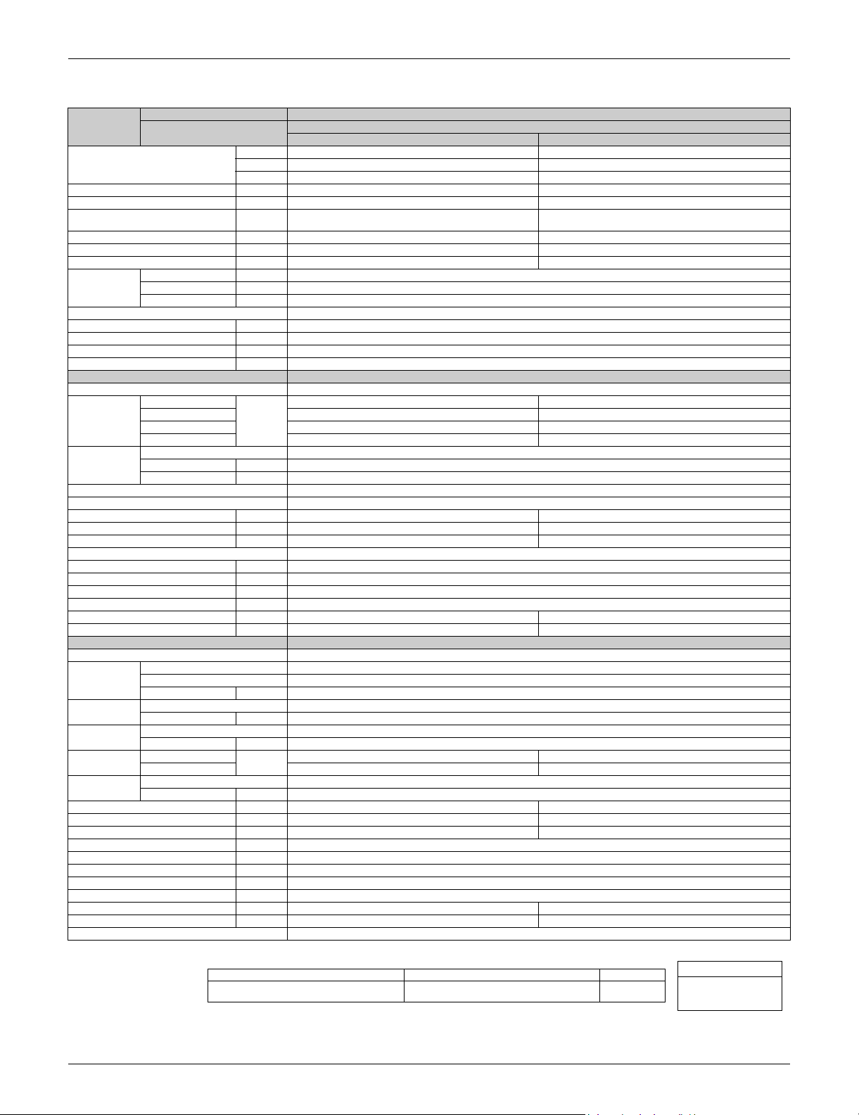
1.2 FDXS Series
Category Functions
Basic
Function
Compressor Oval Scroll Compressor —
Comfortable
Airflow
Comfort
Control
Operation Automatic Operation Low Temperature Cooling Operation
Lifestyle
Convenience
Inverter (with Inverter Power Control) Health &
Operation Limit for Cooling (°FDB)
Operation Limit for Heating (°FWB)
PAM Control
Swing Compressor Air Filter (Prefilter)
Rotary Compressor — Wipe-clean Flat Panel —
Reluctance DC Motor Washable Grille —
Power-Airflow Louver (Horizontal Blade) — MOLD PROOF Operation —
Power-Airflow Dual Louvers — Heating Dry Operation —
Power-Airflow Diffuser — Good-Sleep Cooling Operation —
Wide-Angle Fins (Vertical Blades) — Timer WEEKLY TIMER Operation —
Vertical Auto-Swing (Up and Down) — 24-Hour ON/OFF TIMER
Horizontal Auto-Swing (Right and Left) — NIGHT SET Mode
3-D Airflow — Worry Free
COMFORT AIRFLOW Operation — Self-Diagnosis (Digital, LED) Display
Auto Fan Speed Wiring Error Check Function —
Indoor Unit Quiet Operation
NIGHT QUIET Mode (Automatic) — Flexibility Multi-Split / Split Type Compatible Indoor Unit
OUTDOOR UNIT QUIET Operation (Manual) H/P, C/O Compatible Indoor Unit —
INTELLIGENT EYE Operation — Flexible Power Supply Correspondence —
Quick Warming Function Chargeless 32.8 f t
Hot-Start Function Either Side Drain (Right or Left) —
Automatic Defrosting Power Selection —
Program Dry Function
Fan Only Remote
New POWERFUL Operation
(Non-Inverter)
Inverter POWERFUL Operation
Priority-Room Setting —
COOL / HEAT Mode Lock — DIII-NET Compatible (Adaptor) (Option)
HOME LEAVE Operation — Remote
ECONO Operation Wired (Option)
Indoor Unit [ON/OFF] Button
Signal Receiving Sign
R/C with Back Light
Temperature Display —
14 ~
114.8
5 ~
64.4
—
Category Functions
FDXS09/12LVJU
RXS09/12LVJU
Air-Purifying Filter —
Photocatalytic Deodorizing Filter —
Air-Purifying Filter with Photocatalytic
Deodorizing Function
Titanium Apatite Photocatalytic
Air-Purifying Filter
Auto-Restart (after Power Failure)
Anticorrosion Treatment of Outdoor Heat
Exchanger
°F/°C Changeover R/C Temperature Display
(factory setting: °F)
5-Room Centralized Controller (Option)
Remote Control Adaptor
(Normal Open-Pulse Contact) (Option)
Remote Control Adaptor
(Normal Open Contact) (Option)
Wireless
Clean
“Reliability &
Durability”
Control
Controller
Note: : Holding Functions
— : No Functions
FDXS09/12LVJU
RXS09/12LVJU
—
—
List of Functions 4

SiUS091133
Part 2
Specifications
1. Specifications..............................................................................................6
1.1 FTXS Series................................................................... ..............................6
1.2 FDXS Series...............................................................................................11
5 Specifications
SiUS091133 Specifications
Conversion Formulae
kcal/h = kW × 860
Btu/h = kW × 3412
cfm = m³/min × 35.3
1. Specifications
1.1 FTXS Series
60 Hz, 208 - 230 V
Model
Capacity
Rated (Min.~Max.)
Moisture Removal gal/h (L/h) 0.3 (1.1) — 0.5 (1.9) —
Running Current (Rated) A 3.6 - 3.3 4.4 - 3.9 4.9 - 4.4 4.9 - 4.5
Power Consumption Rated
(Min.~Max.)
Power Factor % 78.8 - 77.7 86.3 - 88.1 92.2 - 92.9 95.2 - 93.7
COP (Rated) W/W 4.47 (4.06 ~ 4.47) 4.46 (4.20 ~ 4.46) 3.74 (4.00 ~ 3.74) 4.35 (4.10 ~ 4.35)
EER (Rated) Btu/h·W 15.3 (13.8 ~ 15.3) 15.2 (14.2 ~ 15.2) 12.8 (13.7 ~ 12.8) 14.8 (14.1 ~ 14.8)
Piping
Connections
Heat Insulation Both Liquid and Gas Pipes Both Liquid and Gas Pipes
Max. Interunit Piping Length ft (m) 65.6 (20) 65.6 (20)
Max. Interunit Height Difference ft (m) 49.2 (15) 49.2 (15)
Chargeless ft (m) 32.8 (10) 32.8 (10)
Amount of Additional Charge of Refrigerant
Indoor Unit FTXS09LVJU FTXS12LVJU
Front Panel Color White White
Airflow Rate
Fan
Air Direction Control Right, Left, Horizontal, Downward Right, Left, Horizontal, Downward
Air Filter Removable / Washable / Mildew Proof Removable / Washable / Mildew Proof
Running Current (Rated) A 0.09 - 0.08 0.11 - 0.10 0.13 - 0.12 0.14 - 0.13
Power Consumption (Rated) W 18 - 18 21 - 21 26 - 26 28 - 28
Power Factor (Rated) % 96.2 - 97.8 91.8 - 91.3 96.2 - 94.2 96.2 - 93.6
Temperature Control Microcomputer Control Microcomputer Control
Dimensions (H × W × D) in. (mm) 11-5/8 × 31-1/2 × 8-7/16 (295 × 800 × 215) 11-5/8 × 31-1/2 × 8-7/16 (295 × 800 × 215)
Packaged Dimensions (H × W × D) in. (mm) 10-13/16 × 34-1/4 × 14-7/16 (274 × 870 × 366) 10-13/16 × 34-1/4 × 14-7/16 (274 × 870 × 366)
Weight (Mass) Lbs (kg) 20 (9) 22 (10)
Gross Weight (Gross Mass) Lbs (kg) 29 (13) 31 (14)
Sound Pressure Level (H / M / L / SL) dB(A) 41 / 33 / 25 / 22 42 / 35 / 28 / 25 45 / 37 / 29 / 23 45 / 39 / 29 / 26
Sound Power Level dB 57 58 61 61
Outdoor Unit RXS09LVJU RXS12LVJU
Casing Color Ivory White Ivory White
Compressor
Refrigerant Oil
Refrigerant
Airflow Rate
Fan
Running Current (Rated) A 3.5 - 3.2 4.3 - 3.8 4.8 - 4.3 4.8 - 4.4
Power Consumption (Rated) W 572 - 572 769 - 769 914 - 914 942 - 942
Power Factor (Rated) % 78.6 - 77.7 86.0 - 88.0 91.5 - 92.4 94.4 - 93.1
Starting Current A 4.4 4.9
Dimensions (H × W × D) in. (mm) 21-5/8 × 30-1/8 × 11-1/4 (550 × 765 × 285) 21-5/8 × 30-1/8 × 11-1/4 (550 × 765 × 285)
Packaged Dimensions (H × W × D) in. (mm) 25 × 34-5/8 × 14-3/16 (635 × 880 × 360) 25 × 34-5/8 × 14-3/16 (635 × 880 × 360)
Weight (Mass) Lbs (kg) 75 (34) 75 (34)
Gross Weight (Gross Mass) Lbs (kg) 89 (41) 89 (41)
Sound Pressure Level (H / L) dB(A) 47 / 43 48 / 44 49 / 44 49 / 45
Sound Power Level (H) dB 61 62 63 63
Drawing No. 3D075491 3D075492
Indoor Unit FTXS09LVJU FTXS12LVJU
Outdoor Unit
kW 2.64 (1.3 ~ 2.64) 3.52 (1.3 ~ 3.52) 3.52 (1.4 ~ 3.52) 4.22 (1.4 ~ 4.22)
Btu/h 9,000 (4,400 ~ 9,000) 12,000 (4,400 ~ 12,000) 12,000 (4,800 ~ 12,000) 14,400 (4,800 ~ 14,400)
kcal/h 2,300 (1,120 ~ 2,270) 3,030 (1,120 ~ 3,030) 3,000 (1,200 ~ 3,030) 3,630 (1,200 ~ 3,630)
W 590 (320 ~ 590) 790 (310 ~ 790) 940 (350 ~ 940) 970 (340 ~ 970)
Liquid in. (mm) 1/4 (6.4) 1/4 (6.4)
Gas in. (mm) 3/8 (9.5) 3/8 (9.5)
Drain in. (mm) 5/8 (16.0) 5/8 (16.0)
oz/ft (g/m) 0.21 (20) 0.21 (20)
H
M 7.9 (279) 9.1 (321) 8.7 (307) 9.5 (335)
L 5.5 (194) 6.6 (233) 5.8 (205) 6.8 (240)
SL 4.1 (145) 6.2 (219) 4.4 (155) 6.0 (212)
Type Cross Flow Fan Cross Flow Fan
Motor Output W 23 23
Speed Steps 5 Steps, Quiet, Auto 5 Steps, Quiet, Auto
Type Hermetically Sealed Swing Type Hermetically Sealed Swing Type
Model 1YC23AEXD 1YC23AEXD
Motor Output W 600 600
Type FVC50K FVC50K
Charge oz (L) 12.5 (0.375) 12.5 (0.375)
Type R-410A R-410A
Charge Lbs (kg) 2.43 (1.1) 2.65 (1.2)
H
L 28.0 (989) 23.8 (840) 28.0 (989) 23.8 (840)
Type Propeller Propeller
Motor Output W 23 23
m³/min
(cfm)
m³/min
(cfm)
Cooling Heating Cooling Heating
10.8 (381) 11.9 (420) 11.4 (403) 12.4 (438)
31.2 (1,102) 28.1 (992) 33.5 (1,183) 28.1 (992)
RXS09LVJU RXS12LVJU
Specifications 6
Note: The data are based on the conditions shown in the table below.
Indoor ; 80°FDB (26.7°CDB) / 67°FWB (19.4°CWB)
Outdoor ; 95°FDB (35°CDB) / 75°FWB (24°CWB)
Cooling Heating Piping Length
Indoor ; 70°FDB (21°CDB) / 60°FWB (15.6°CWB)
Outdoor ; 47°FDB (8.3°CDB) / 43°FWB (6°CWB)
25 ft (7.5 m)
Specifications SiUS091133
Conversion Formulae
kcal/h = kW × 860
Btu/h = kW × 3412
cfm = m³/min × 35.3
60 Hz, 208 - 230 V
Model
Capacity
Rated (Min.~Max.)
Moisture Removal gal/h (L/h) 0.8 (3.0) — 1.0 (3.8) —
Running Current (Rated) A 5.2 - 4.7 6.5 - 5.9 7.1 - 6.4 8.4 - 7.6
Power Consumption Rated
(Min.~Max.)
Power Factor % 96.2 - 96.2 97.6 - 97.3 96.2 - 96.5 97.9 - 97.8
COP (Rated) W/W 4.23 (3.78 ~ 4.23) 4.00 (3.78 ~ 4.00) 3.72 (3.78 ~ 3.72) 3.70 (3.78 ~ 3.70)
EER (Rated) Btu/h·W 14.4 (12.9 ~ 14.4) 13.6 (12.9 ~ 13.6) 12.7 (12.9 ~ 12.7) 12.6 (12.9 ~ 12.6)
Piping
Connections
Heat Insulation Both Liquid and Gas Pipes Both Liquid and Gas Pipes
Max. Interunit Piping Length ft (m) 98.4 (30) 98.4 (30)
Max. Interunit Height Difference ft (m) 65.6 (20) 65.6 (20)
Chargeless ft (m) 32.8 (10) 32.8 (10)
Amount of Additional Charge of Refrigerant
Indoor Unit FTXS15LVJU FTXS18LVJU
Front Panel Color White White
Airflow Rate
Fan
Air Direction Control Right, Left, Horizontal, Downward Right, Left, Horizontal, Downward
Air Filter Removable / Washable / Mildew Proof Removable / Washable / Mildew Proof
Running Current (Rated) A 0.31 - 0.29 0.31 - 0.29 0.32 - 0.30 0.32 - 0.30
Power Consumption (Rated) W 38 - 38 38 - 38 38 - 38 38 - 38
Power Factor (Rated) % 58.9 - 57.0 58.9 - 57.0 57.1 - 55.1 57.1 - 55.1
Temperature Control Microcomputer Control Microcomputer Control
Dimensions (H × W × D) in. (mm) 13-3/8 × 41-5/16 × 9-3/4 (340 × 1,050 × 248) 13-3/8 × 41-5/16 × 9-3/4 (340 × 1,050 × 248)
Packaged Dimensions (H × W × D) in. (mm) 13 × 45-11/16 × 16-7/8 (331 × 1,160 × 429) 13 × 45-11/16 × 16-7/8 (331 × 1,160 × 429)
Weight (Mass) Lbs (kg) 31 (14) 31 (14)
Gross Weight (Gross Mass) Lbs (kg) 44 (20) 44 (20)
Sound Pressure Level (H / M / L / SL) dB(A) 45 / 40 / 35 / 32 43 / 38 / 33 / 30 46 / 41 / 36 / 33 45 / 40 / 35 / 32
Sound Power Level dB 61 59 62 61
Outdoor Unit RXS15LVJU RXS18LVJU
Casing Color Ivory White Ivory White
Compressor
Refrigerant Oil
Refrigerant
Airflow Rate
Fan
Running Current (Rated) A 5.0 - 4.5 6.3 - 5.7 6.9 - 6.2 8.2 - 7.4
Power Consumption (Rated) W 1,002 - 1,002 1,282 - 1,282 1,382 - 1,382 1,672 - 1,672
Power Factor (Rated) % 96.3 - 96.8 97.8 - 97.8 96.3 - 96.9 98.0 - 98.2
Starting Current A 6.5 8.4
Dimensions (H × W × D) in. (mm) 28-15/16 × 32-1/2 × 11-13/16 (735 × 825 × 300) 28-15/16 × 32-1/2 × 11-13/16 (735 × 825 × 300)
Packaged Dimensions (H × W × D) in. (mm) 31-7/16 × 37-15/16 × 15-3/8 (798 × 964 × 390) 31-7/16 × 37-15/16 × 15-3/8 (798 × 964 × 390)
Weight (Mass) Lbs (kg) 104 (47) 104 (47)
Gross Weight (Gross Mass) Lbs (kg) 117 (53) 117 (53)
Sound Pressure Level (H / L) dB(A) 47 / 44 48 / 45 49 / 46 49 / 46
Sound Power Level (H) dB 61 62 63 63
Drawing No. 3D075043 3D075044
Indoor Unit FTXS15LVJU FTXS18LVJU
Outdoor Unit
kW 4.4 (1.7 ~ 4.4) 5.28 (1.7 ~ 5.28) 5.28 (1.7 ~ 5.28) 6.33 (1.7 ~ 6.33)
Btu/h 15,000 (5,800 ~ 15,000) 18,000 (5,800 ~ 18,000) 18,000 (5,800 ~ 18,000) 21,600 (5,800 ~ 21,600)
kcal/h 3,780 (1,460 ~ 3,780) 4,540 (1,460 ~ 4,540) 4,540 (1,460 ~ 4,540) 5,440 (1,460 ~ 5,440)
W 1,040 (450 ~ 1,040) 1,320 (450 ~ 1,320) 1,420 (450 ~ 1,420) 1,710 (450 ~ 1,710)
Liquid in. (mm) 1/4 (6.4) 1/4 (6.4)
Gas in. (mm) 1/2 (12.7) 1/2 (12.7)
Drain in. (mm) 5/8 (16.0) 5/8 (16.0)
oz/ft (g/m) 0.21 (20) 0.21 (20)
H
M 13.5 (477) 14.3 (505) 13.7 (484) 14.9 (526)
L 10.9 (385) 11.8 (417) 10.9 (385) 12.2 (431)
SL 10.2 (360) 10.5 (371) 10.2 (360) 11.3 (399)
Type Cross Flow Fan Cross Flow Fan
Motor Output W 48 48
Speed Steps 5 Steps, Quiet, Auto 5 Steps, Quiet, Auto
Type Hermetically Sealed Swing Type Hermetically Sealed Swing Type
Model 2YC36BXD 2YC36BXD
Motor Output W 1,100 1,100
Type FVC50K FVC50K
Charge oz (L) 21.8 (0.650) 21.8 (0.650)
Type R-410A R-410A
Charge Lbs (kg) 3.97 (1.8) 3.97 (1.8)
H
L 41.6 (1,469) 37.0 (1,306) 42.3 (1,494) 37.6 (1,328)
Type Propeller Propeller
Motor Output W 53 53
m³/min
(cfm)
m³/min
(cfm)
Cooling Heating Cooling Heating
16.1 (568) 16.8 (593) 16.5 (583) 17.7 (625)
48.5 (1,713) 39.8 (1,405) 50.4 (1,780) 40.9 (1,444)
RXS15LVJU RXS18LVJU
7 Specifications
Note: The data are based on the conditions shown in the table below.
Indoor ; 80°FDB (26.7°CDB) / 67°FWB (19.4°CWB)
Outdoor ; 95°FDB (35°CDB) / 75°FWB (24°CWB)
Cooling Heating Piping Length
Indoor ; 70°FDB (21°CDB) / 60°FWB (15.6°CWB)
Outdoor ; 47°FDB (8.3°CDB) / 43°FWB (6°CWB)
25 ft (7.5 m)
SiUS091133 Specifications
Conversion Formulae
kcal/h = kW × 860
Btu/h = kW × 3412
cfm = m³/min × 35.3
60 Hz, 208 - 230 V
Model
Capacity
Rated (Min.~Max.)
Moisture Removal gal/h (L/h) 1.2 (4.5) —
Running Current (Rated) A 8.4 ~ 7.6 10.7 ~ 9.7
Power Consumption Rated
(Min.~Max.)
Power Factor % 98.4 - 98.4 99.3 - 99.1
COP (Rated) W/W 3.66 (4.04 ~ 3.66) 3.37 (4.40 ~ 3.37)
EER (Rated)
Piping
Connections
Heat Insulation Both Liquid and Gas Pipes
Max. Interunit Piping Length ft (m) 98.4 (30)
Max. Interunit Height Difference ft (m) 65.6 (20)
Chargeless ft (m) 32.8 (10)
Amount of Additional Charge of Refrigerant
Indoor Unit FTXS24LVJU
Front Panel Color White
Airflow Rate
Fan
Air Direction Control Right, Left, Horizontal, Downward
Air Filter Removable / Washable / Mildew Proof
Running Current (Rated) A 0.57 - 0.51 0.57 - 0.51
Power Consumption (Rated) W 69 - 68 69 - 68
Power Factor (Rated) % 58.2 - 58.0 58.2 - 58.0
Temperature Control Microcomputer Control
Dimensions (H × W × D) in. (mm) 13-3/8 × 41-5/16 × 9-3/4 (340 × 1,050 × 248)
Packaged Dimensions (H × W × D) in. (mm) 13 × 45-11/16 × 16-7/8 (331 × 1,160 × 429)
Weight (Mass) Lbs (kg) 31 (14)
Gross Weight (Gross Mass) Lbs (kg) 46 (21)
Sound Pressure Level (H / M / L / SL) dB(A) 51 / 44 / 37 / 34 48 / 42 / 37 / 34
Sound Power Level dBA 67 64
Outdoor Unit RXS24LVJU
Casing Color Ivory White
Compressor
Refrigerant Oil
Refrigerant
Airflow Rate
Fan
Running Current (Rated) A 8.1 - 7.3 10.4 - 9.4
Power Consumption (Rated) W 1,651 - 1,652 2,141 - 2,142
Power Factor (Rated) % 98.0 - 98.4 99.0 - 99.1
Starting Current A 10.7
Dimensions (H × W × D) in. (mm) 30-5/16 × 35-7/16 × 12-5/8 (770 × 900 × 320)
Packaged Dimensions (H × W × D) in. (mm) 35-7/16 × 36-7/16 × 15-3/8 (900 × 925 × 390)
Weight (Mass) Lbs (kg) 159 (72)
Gross Weight (Gross Mass) Lbs (kg) 178 (81)
Sound Pressure Level (H / L) dB(A) 52 / 49 52 / 49
Sound Power Level (H) dBA 66 66
Drawing No. 3D075045
Indoor Unit FTXS24LVJU
Outdoor Unit
kW 6.30 (2.3 ~ 6.30) 7.44 (2.3 ~ 7.44)
Btu/h 21,500 (7,800 ~ 21,500) 25,400 (7,800 ~ 25,400)
kcal/h 5,400 (1,980 ~ 5,420) 6,400 (1,980 ~ 6,400)
W 1,720 (570 ~ 1,720) 2,210 (520 ~ 2,210)
Liquid in. (mm) 1/4 (6.4)
Gas in. (mm) 5/8 (15.9)
Drain in. (mm) 5/8 (16.0)
H
M 14.0 (494) 16.2 (572)
L 9.9 (350) 12.6 (445)
SL 9.3 (328) 11.4 (403)
Type Cross Flow Fan
Motor Output W 48
Speed Steps 5 Steps, Quiet, Auto
Type Hermetically Sealed Swing Type
Model 2YC63BXD
Motor Output W 1,920
Type FVC50K
Charge oz (L) 25.2 (0.750)
Type R-410A
Charge Lbs (kg) 5.07 (2.3)
H
L 46.0 (1,624) 46.0 (1,624)
Type Propeller
Motor Output W 66
Btu/h·W
oz/ft (g/m) 0.21 (20)
m³/min
(cfm)
m³/min
(cfm)
Cooling Heating
12.5 (13.7 ~ 12.5) 11.5 (15.0 ~ 11.5)
18.2 (643) 19.8 (699)
54.5 (1,924) 52.5 (1,854)
RXS24LVJU
Specifications 8
Note: The data are based on the conditions shown in the table below.
Indoor ; 80°FDB (26.7°CDB) / 67°FWB (19.4°CWB)
Outdoor ; 95°FDB (35°CDB) / 75°FWB (24°CWB)
Cooling Heating Piping Length
Indoor ; 70°FDB (21°CDB) / 60°FWB (15.6°CWB)
Outdoor ; 47°FDB (8.3°CDB) / 43°FWB (6°CWB)
25 ft (7.5 m)
Specifications SiUS091133
Conversion Formulae
kcal/h = kW × 860
Btu/h = kW × 3412
cfm = m³/min × 35.3
60 Hz, 208 - 230 V
Model
Capacity
Rated (Min. ~ Max.)
Moisture Removal gal/h (L/h) 1.5 (5.8) 1.8 (6.9)
Running Current (Rated) A 13.6 - 12.2 19.4 - 18.8
Power Consumption Rated
(Min. ~ Max.)
Power Factor (Rated) % 99.0 - 99.8 99.1 - 99.4
COP (Rated) W/W 3.14 (4.84 ~ 3.14) 2.55 - 2.44 (4.84 ~ 2.55 - 2.44)
EER (Rated) Btu/h·W 10.71 (16.45 ~ 10.71) 8.75 - 8.37 (16.45 ~ 8.75 - 8.37)
Piping
Connections
Heat Insulation Both Liquid and Gas Pipes Both Liquid and Gas Pipes
Max. Interunit Piping Length ft (m) 98.4 (30) 98.4 (30)
Max. Interunit Height Difference ft (m) 65.6 (20) 65.6 (20)
Chargeless ft (m) 32 (10) 32 (10)
Amount of Additional Charge of Refrigerant
Indoor Unit FTXS30LVJU FTXS36LVJU
Front Panel Color White White
Airflow Rate
Fan
Air Direction Control Right, Left, Horizontal, Downward Right, Left, Horizontal, Downward
Air Filter Removable / Washable / Mildew Proof Removable / Washable / Mildew Proof
Running Current (Rated) A 0.38 - 0.34 0.38 - 0.34
Power Consumption (Rated) W 77 77
Power Factor (Rated) % 97.4 - 98.5 97.4 - 98.5
Temperature Control Microcomputer Control Microcomputer Control
Dimensions (H × W × D) in. (mm) 13-3/8 × 47-1/4 × 9-7/16 (340 × 1,200 × 240) 13-3/8 × 47-1/4 × 9-7/16 (340 × 1,200 × 240)
Packaged Dimensions (H × W × D) in. (mm) 12-13/16 × 51-9/16 × 16-7/8 (325 × 1,310 × 429) 12-13/16 × 51-9/16 × 16-7/8 (325 × 1,310 × 429)
Weight (Mass) Lbs (kg) 38 (17) 38 (17)
Gross Weight (Gross Mass) Lbs (kg) 51 (23) 51 (23)
Sound Pressure Level (H / M / L / SL) dB(A) 47 / 45 / 40 / 37 49 / 45 / 40 / 37
Sound Power Level dB 63 65
Outdoor Unit RKS30LVJU RKS36LVJU
Casing Color Ivory White Ivory White
Compressor
Refrigerant Oil
Refrigerant
Airflow Rate
Fan
Running Current (Rated) A 13.22 - 11.86 19.02 - 18.46
Power Consumption (Rated) W 2,723 3,923 - 4,223
Power Factor (Rated) % 99.0 - 99.8 99.2 - 99.5
Starting Current A 18.9 19.4
Dimensions (H × W × D) in. (mm) 38-15/16 × 37 × 12-5/8 (990 × 940 × 320) 38-15/16 × 37 × 12-5/8 (990 × 940 × 320)
Packaged Dimensions (H × W × D) in. (mm) 43-7/8 × 39-7/16 × 16-11/16 (1,114 × 1,003 × 425) 43-7/8 × 39-7/16 × 16-11/16 (1,114 × 1,003 × 425)
Weight (Mass) Lbs (kg) 179 (81) 179 (81)
Gross Weight (Gross Mass) Lbs (kg) 204 (93) 204 (93)
Sound Pressure Level (H / SL) dB(A) 54 / 51 54 / 51
Sound Power Level (H) dB 68 68
Drawing No. 3D075052 3D075064
Indoor Unit FTXS30LVJU FTXS36LVJU
Outdoor Unit RKS30LVJU RKS36LVJU
Liquid in. (mm) 3/8 (9.5) 3/8 (9.5)
Gas in. (mm) 5/8 (15.9) 5/8 (15.9)
Drain in. (mm) 5/8 (16.0) 5/8 (16.0)
H
M 17.3 (611) 18.0 (635)
L 14.7 (519) 14.7 (519)
SL 13.4 (473) 13.4 (473)
Type Cross Flow Fan Cross Flow Fan
Motor Output W 64 64
Speed Steps 5 Steps, Quiet, Auto 5 Steps, Quiet, Auto
Type Hermetically Sealed Swing Type Hermetically Sealed Swing Type
Model 2YC63FXD 2YC63FXD
Motor Output W 2,030 2,030
Type FVC50K FVC50K
Charge oz (L) 25.5 (0.75) 25.5 (0.75)
Type R-410A R-410A
Charge Lbs (kg) 6.17 (2.8) 6.17 (2.8)
H
SL 65.6 (2,316) 65.6 (2,316)
Type Propeller Propeller
Motor Output W 200 200
kW 8.8 (3.0 ~ 8.8) 10.2 - 10.5 (3.0 ~ 10.2 - 10.5)
Btu/h 30,000 (10,200 ~ 30,000) 35,000 - 36,000 (10,200 ~ 35,000 - 36,000)
kcal/h 7,570 (2,580 ~ 7,570) 8,770 - 9,030 (2,580 ~ 8,770 - 9,030)
W 2,800 (620 ~ 2,800) 4,000 - 4,300 (620 ~ 4,000 - 4,300)
oz/ft (g/m) 0.54 (50) 0.54 (50)
20.0 (706) 21.8 (770)
m³/min
(cfm)
m³/min
(cfm)
74.4 (2,627) 74.4 (2,627)
9 Specifications
Note: The data are based on the conditions shown in the table below.
Indoor ; 80°FDB (26.7°CDB) / 67°FWB (19.4°CWB)
Outdoor ; 95°FDB (35°CDB) / 75°FWB (24°CWB)
Cooling Piping Length
25 ft (7.5 m)
SiUS091133 Specifications
Conversion Formulae
kcal/h = kW × 860
Btu/h = kW × 3412
cfm = m³/min × 35.3
60 Hz, 208 - 230 V
Model
Capacity
Rated (Min. ~ Max.)
Moisture Removal gal/h (L/h) 1.5 (5.8) — 1.8 (6.9) —
Running Current (Rated) A 13.6 - 12.2 18.9 - 17.1 19.4 - 18.8 18.4 - 18.4
Power Consumption Rated
(Min. ~ Max.)
Power Factor (Rated) % 99.0 - 99.8 99.2 - 99.2 99.1 - 99.4 99.3 - 99.2
COP (Rated) W/W 3.14 (4.84 ~ 3.14) 2.62 (4.84 ~ 2.62)
EER (Rated) Btu/h·W 10.71 (16.45 ~ 10.71) 8.92 (16.45 ~ 8.92)
Piping
Connections
Heat Insulation Both Liquid and Gas Pipes Both Liquid and Gas Pipes
Max. Interunit Piping Length ft (m) 98.4 (30) 98.4 (30)
Max. Interunit Height Difference ft (m) 65.6 (20) 65.6 (20)
Chargeless ft (m) 32 (10) 32 (10)
Amount of Additional Charge of Refrigerant
Indoor Unit FTXS30LVJU FTXS36LVJU
Front Panel Color White White
Airflow Rate
Fan
Air Direction Control Right, Left, Horizontal, Downward Right, Left, Horizontal, Downward
Air Filter Removable / Washable / Mildew Proof Removable / Washable / Mildew Proof
Running Current (Rated) A 0.38 - 0.34 0.38 - 0.34 0.38 - 0.34 0.38 - 0.34
Power Consumption (Rated) W 77 77 77 77
Power Factor (Rated) % 97.4 - 98.5 97.4 - 98.5 97.4 - 98.5 97.4 - 98.5
Temperature Control Microcomputer Control Microcomputer Control
Dimensions (H × W × D) in. (mm) 13-3/8 × 47-1/4 × 9-7/16 (340 × 1,200 × 240) 13-3/8 × 47-1/4 × 9-7/16 (340 × 1,200 × 240)
Packaged Dimensions (H × W × D) in. (mm) 12-13/16 × 51-9/16 × 16-7/8 (325 × 1,310 × 429) 12-13/16 × 51-9/16 × 16-7/8 (325 × 1,310 × 429)
Weight (Mass) Lbs (kg) 38 (17) 38 (17)
Gross Weight (Gross Mass) Lbs (kg) 51 (23) 51 (23)
Sound Pressure Level (H / M / L / SL) dB(A) 47 / 45 / 40 / 37 47 / 44 / 38 / 35 49 / 45 / 40 / 37 49 / 44 / 38 / 35
Sound Power Level dB 63 63 65 65
Outdoor Unit RXS30LVJU RXS36LVJU
Casing Color Ivory White Ivory White
Compressor
Refrigerant Oil
Refrigerant
Airflow Rate
Fan
Running Current (Rated) A 13.22 - 11.86 18.52 - 16.76 19.02 - 18.46 18.02 - 18.06
Power Consumption (Rated) W 2,723 3,823 3,923 - 4,223 3,723 - 4,123
Power Factor (Rated) % 99.0 - 99.8 99.2 - 99.2 99.2 - 99.5 99.3 - 99.3
Starting Current A 18.9 19.4
Dimensions (H × W × D) in. (mm) 38-15/16 × 37 × 12-5/8 (990 × 940 × 320) 38-15/16 × 37 × 12-5/8 (990 × 940 × 320)
Packaged Dimensions (H × W × D) in. (mm) 43-7/8 × 39-7/16 × 16-11/16 (1,114 × 1,003 × 425) 43-7/8 × 39-7/16 × 16-11/16 (1,114 × 1,003 × 425)
Weight (Mass) Lbs (kg) 179 (81) 179 (81)
Gross Weight (Gross Mass) Lbs (kg) 204 (93) 204 (93)
Sound Pressure Level (H / SL) dB(A) 54 / 51 55 / 51 54 / 51 55 / 51
Sound Power Level (H) dB 68 69 68 69
Drawing No. 3D075050 3D075055
Indoor Unit FTXS30LVJU FTXS36LVJU
Outdoor Unit
kW 8.8 (3.0 ~ 8.8) 10.2 (3.0 ~ 10.2) 10.2 - 10.5 (3.0 ~ 10.2 - 10.5) 10.5 - 11.1 (3.0 ~ 10.5 - 11.1)
Btu/h 30,000 (10,200 ~ 30,000) 34,800 (10,200 ~ 34,800)
kcal/h 7,570 (2,580 ~ 7,570) 8,770 (2,580 ~ 8,770)
W 2,800 (620 ~ 2,800) 3,900 (620 ~ 3,900)
Liquid in. (mm) 3/8 (9.5) 3/8 (9.5)
Gas in. (mm) 5/8 (15.9) 5/8 (15.9)
Drain in. (mm) 5/8 (16.0) 5/8 (16.0)
oz/ft (g/m) 0.54 (50) 0.54 (50)
H
M 17.3 (611) 17.3 (611) 18.0 (635) 18.6 (657)
L 14.7 (519) 14.7 (519) 14.7 (519) 14.7 (519)
SL 13.4 (473) 13.3 (469) 13.4 (473) 13.3 (469)
Type Cross Flow Fan Cross Flow Fan
Motor Output W 64 64
Speed Steps 5 Steps, Quiet, Auto 5 Steps, Quiet, Auto
Type Hermetically Sealed Swing Type Hermetically Sealed Swing Type
Model 2YC63FXD 2YC63FXD
Motor Output W 2,030 2,030
Type FVC50K FVC50K
Charge oz (L) 25.5 (0.75) 25.5 (0.75)
Type R-410A R-410A
Charge Lbs (kg) 6.17 (2.8) 6.17 (2.8)
H
SL 65.6 (2,316) 65.6 (2,316) 65.6 (2,316) 65.6 (2,316)
Type Propeller Propeller
Motor Output W 200 200
m³/min
(cfm)
m³/min
(cfm)
Cooling Heating Cooling Heating
20.0 (706) 20.1 (710) 21.8 (770) 22.9 (808)
74.4 (2,627) 74.4 (2,627) 74.4 (2,627) 74.4 (2,627)
RXS30LVJU RXS36LVJU
35,000 - 36,000 (10,200 ~ 35,000 - 36,000) 36,000 - 38,000 (10,200 ~ 36,000 - 38,000)
8,770 - 9,030 (2,580 ~ 8,770 - 9,030) 9,030 - 9,550 (2,580 ~ 9,030 - 9,550)
4,000 - 4,300 (620 ~ 4,000 - 4,300) 3,800 - 4,200 (620 ~ 3,800 - 4,200)
2.55 - 2.44 (4.84 ~ 2.55 - 2.44) 2.76 - 2.64 (4.84 ~ 2.76 - 2.64)
8.75 - 8.37 (16.45 ~ 8.75 - 8.37) 9.47 - 9.05 (16.45 ~ 9.47 - 9.05)
Specifications 10
Note: The data are based on the conditions shown in the table below.
Indoor ; 80°FDB (26.7°CDB) / 67°FWB (19.4°CWB)
Outdoor ; 95°FDB (35°CDB) / 75°FWB (24°CWB)
Cooling Heating Piping Length
Indoor ; 70°FDB (21°CDB) / 60°FWB (15.6°CWB)
Outdoor ; 47°FDB (8.3°CDB) / 43°FWB (6°CWB)
25 ft (7.5 m)
Specifications SiUS091133
Conversion Formulae
kcal/h = kW × 860
Btu/h = kW × 3412
cfm = m³/min × 35.3
1.2 FDXS Series
60 Hz, 208 - 230 V
Model
Capacity
Rated (Min.~Max.)
Moisture Removal gal/h (L/h) 2.5 (9.5) — 4.0 (15.1) —
Running Current (Rated) A 4.6 - 4.2 4.5 - 4.1 6.4 - 5.8 4.9 - 4.4
Power Consumption Rated
(Min.~Max.)
Power Factor % 79.4 - 78.7 90.8 - 90.1 94.7 - 94.5 94.2 - 94.9
COP (Rated) W/W 3.28 (4.33 ~ 3.28) 3.45 (4.48 ~ 3.45) 2.67 (4.67 ~ 2.67) 3.51 (4.83 ~ 3.51)
EER (Rated) Btu/h·W 11.2 (14.7 ~ 11.2) 11.8 (15.2 ~ 11.8) 9.1 (16.0 ~ 9.1) 12.0 (16.6 ~ 12.0)
Piping
Connections
Heat Insulation Both Liquid and Gas Pipes Both Liquid and Gas Pipes
Max. Interunit Piping Length ft (m) 65.6 (20) 65.6 (20)
Max. Interunit Height Difference ft (m) 49.2 (15) 49.2 (15)
Chargeless ft (m) 32.8 (10) 32.8 (10)
Amount of Additional Charge of Refrigerant
Indoor Unit FDXS09LVJU FDXS12LVJU
External Static Pressure ”Wg (Pa) 0.12 (30) 0.12 (30)
Airflow Rate
Fan
Air Filter Removable / Washable / Mildew Proof Removable / Washable / Mildew Proof
Running Current (Rated) A 0.58 - 0.52 0.58 - 0.52 0.58 - 0.52 0.58 - 0.52
Power Consumption (Rated) W 72 - 72 72 - 72 72 - 72 72 - 72
Power Factor (Rated) % 59.7 - 60.2 59.7 - 60.2 59.7 - 60.2 59.7 - 60.2
Temperature Control Microcomputer Control Microcomputer Control
Dimensions (H × W × D) in. (mm) 7-7/8 × 27-9/16 × 24-7/16 (200 × 700 × 620) 7-7/8 × 27-9/16 × 24-7/16 (200 × 700 × 620)
Packaged Dimensions (H × W × D) in. (mm) 10-13/16 × 36-5/16 × 30-1/4 (274 × 923 × 768) 10-13/16 × 36-5/16 × 30-1/4 (274 × 923 × 768)
Weight (Mass) Lbs (kg) 47 (21) 47 (21)
Gross Weight (Gross Mass) Lbs (kg) 64 (29) 64 (29)
Sound Pressure Level (H / M / L) dB(A) 35 / 33 / 31 35 / 33 / 31 35 / 33 / 31 35 / 33 / 31
Sound Power Level dBA 51 51 51 51
Outdoor Unit RXS09LVJU RXS12LVJU
Casing Color Ivory White Ivory White
Compressor
Refrigerant Oil
Refrigerant
Airflow Rate
Fan
Running Current (Rated) A 4.2 - 3.8 4.1 - 3.8 6.0 - 5.5 4.5 - 4.1
Power Consumption (Rated) W 688 - 688 778 - 778 1,188 - 1,188 888 - 888
Power Factor (Rated) % 78.8 - 78.7 91.2 - 89.0 95.2 - 93.9 94.9 - 94.2
Starting Current A 4.6 6.4
Dimensions (H × W × D) in. (mm) 21-5/8 × 30-1/8 × 11-1/4 (550 × 765 × 285) 21-5/8 × 30-1/8 × 11-1/4 (550 × 765 × 285)
Packaged Dimensions (H × W × D) in. (mm) 25 × 34-5/8 × 14-3/16 (635 × 880 × 360) 25 × 34-5/8 × 14-3/16 (635 × 880 × 360)
Weight (Mass) Lbs (kg) 75 (34) 75 (34)
Gross Weight (Gross Mass) Lbs (kg) 89 (41) 89 (41)
Sound Pressure Level (H / L) dB(A) 47 / 43 48 / 44 49 / 44 49 / 45
Sound Power Level (H) dBA 61 62 63 63
Drawing No. 3D075493 3D075494
Indoor Unit FDXS09LVJU FDXS12LVJU
Outdoor Unit
kW 2.49 (1.30 ~ 2.49) 2.93 (1.30 ~ 2.93) 3.37 (1.40 ~ 3.37) 3.37 (1.40 ~ 3.37)
Btu/h 8,500 (4,400 ~ 8,500) 10,000 (4,400 ~ 10,000) 11,500 (4,800 ~ 11,500) 11,500 (4,800 ~ 11,500)
kcal/h 2,140 (1,120 ~ 2,140) 2,520 (1,120 ~ 2,520) 2,900 (1,200 ~ 2,900) 2,900 (1,200 ~ 2,900)
W 760 (300 ~ 760) 850 (290 ~ 850) 1,260 (300 ~ 1,260) 960 (290 ~ 960)
Liquid in. (mm) 1/4 (6.4) 1/4 (6.4)
Gas in. (mm) 3/8 (9.5) 3/8 (9.5)
Drain in. (mm) 25/32 (20.0) 25/32 (20.0)
oz/ft (g/m) 0.21 (20) 0.21 (20)
H
M 7.9 (280) 7.9 (280) 7.9 (280) 7.9 (280)
L 7.4 (260) 7.4 (260) 7.4 (260) 7.4 (260)
SL 6.7 (235) 6.7 (235) 6.7 (235) 6.7 (235)
Type Sirocco Fan Sirocco Fan
Motor Output W 62 62
Speed Steps 5 Steps, Quiet, Auto 5 Steps, Quiet, Auto
Type Hermetically Sealed Swing Type Hermetically Sealed Swing Type
Model 1YC23AEXD 1YC23AEXD
Motor Output W 600 600
Type FVC50K FVC50K
Charge oz (L) 12.5 (0.375) 12.5 (0.375)
Type R-410A R-410A
Charge Lbs (kg) 2.43 (1.1) 2.65 (1.2)
H
L 28.0 (989) 23.8 (840) 28.0 (989) 23.8 (840)
Type Propeller Propeller
Motor Output W 23 23
m³/min
(cfm)
m³/min
(cfm)
Cooling Heating Cooling Heating
8.6 (305) 8.6 (305) 8.6 (305) 8.6 (305)
31.2 (1,102) 28.1 (992) 33.5 (1,183) 28.1 (992)
RXS09LVJU RXS12LVJU
11 Specifications
Note: The data are based on the conditions shown in the table below.
Indoor ; 80°FDB (26.7°CDB) / 67°FWB (19.4°CWB)
Outdoor ; 95°FDB (35°CDB) / 75°FWB (24°CWB)
Cooling Heating Piping Length
Indoor ; 70°FDB (21°CDB) / 60°FWB (15.6°CWB)
Outdoor ; 47°FDB (8.3°CDB) / 43°FWB (6°CWB)
25 ft (7.5 m)

SiUS091133
Part 3
Printed Circuit Board
Connector Wiring Diagram
1. Indoor Unit.................................................................................................13
1.1 FTXS09/12LVJU ........................................................................................13
1.2 FTXS15/18/24/30/36LVJU .........................................................................16
1.3 FDXS09/12LVJU........................................................................................ 19
2. Outdoor Unit..............................................................................................21
2.1 RXS09/12LVJU..........................................................................................21
2.2 RXS15/18LVJU..........................................................................................23
2.3 RXS24LVJU, RK(X)S30/36LVJU............................................................... 25
Printed Circuit Board Connector Wiring Diagram 12

Indoor Unit SiUS091133
1. Indoor Unit
1.1 FTXS09/12LVJU
Connectors and
Other Parts
PCB (1): Control PCB
1) S1 Connector for DC fan motor
2) S21 Connector for centralized control (HA)
3) S25 Connector for INTELLIGENT EYE sensor PCB
4) S32 Indoor heat exchanger thermistor
5) S41 Connector for swing motors
6) S46 Connector for display PCB
7) S47 Connector for signal receiver PCB
8) H1, H2, H3, FG Connector for terminal board
9) JA Address setting jumper
Refer to page 388 for detail.
10)JB Fan speed setting when compressor stops for thermostat OFF
JC Power failure recovery function (auto-restart)
Refer to page 390 for detail.
11)LED A LED for service monitor (green)
12)FU1 (F1U) Fuse (3.15 A, 250 V)
13) V1 Varistor
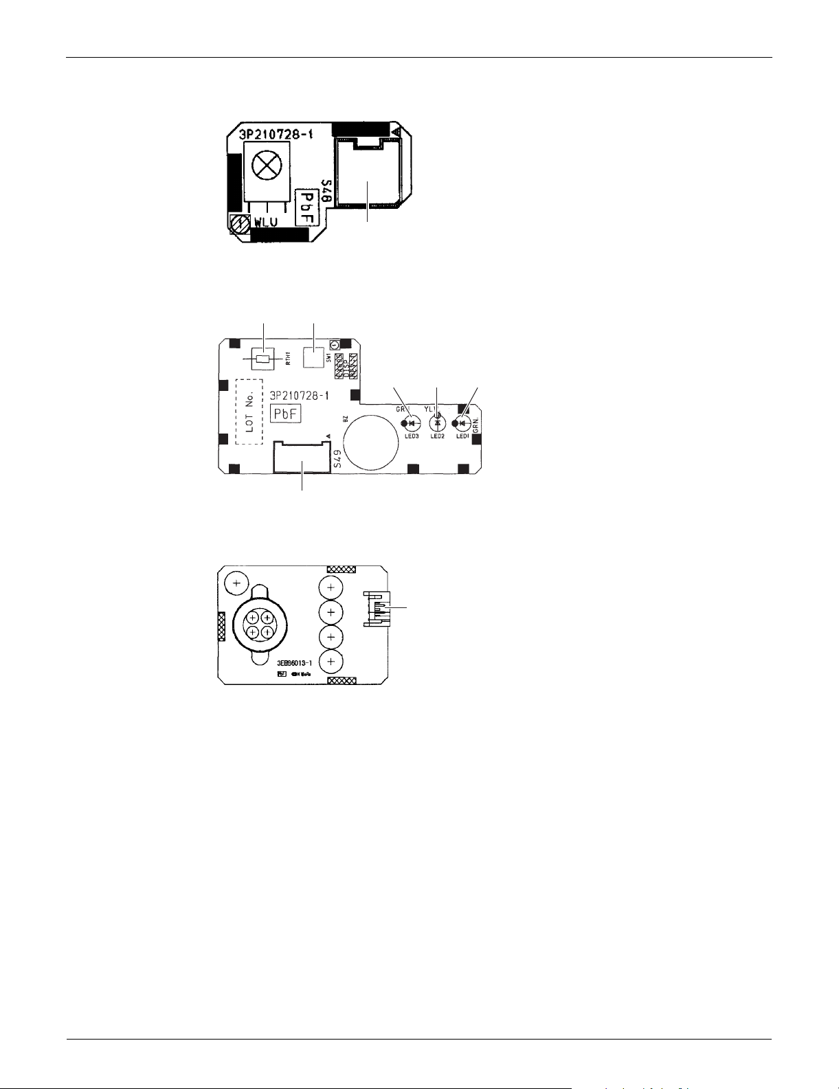
PCB (2): Signal Receiver PCB
1) S48 Connector for control PCB
PCB (3): Display PCB
1) S49 Connector for control PCB
2) SW1 Forced cooling operation [ON/OFF] button
Refer to page 384 for detail.
3) LED1 (H1P) LED for operation (green)
4) LED2 (H2P) LED for timer (yellow)
5) LED3 (H3P) LED for INTELLIGENT EYE (green)
6) RTH1 (R1T) Room temperature thermistor
PCB (4): INTELLIGENT EYE Sensor PCB
1) S26 Connector for control PCB
13 Printed Circuit Board Connector Wiring Diagram
SiUS091133 Indoor Unit
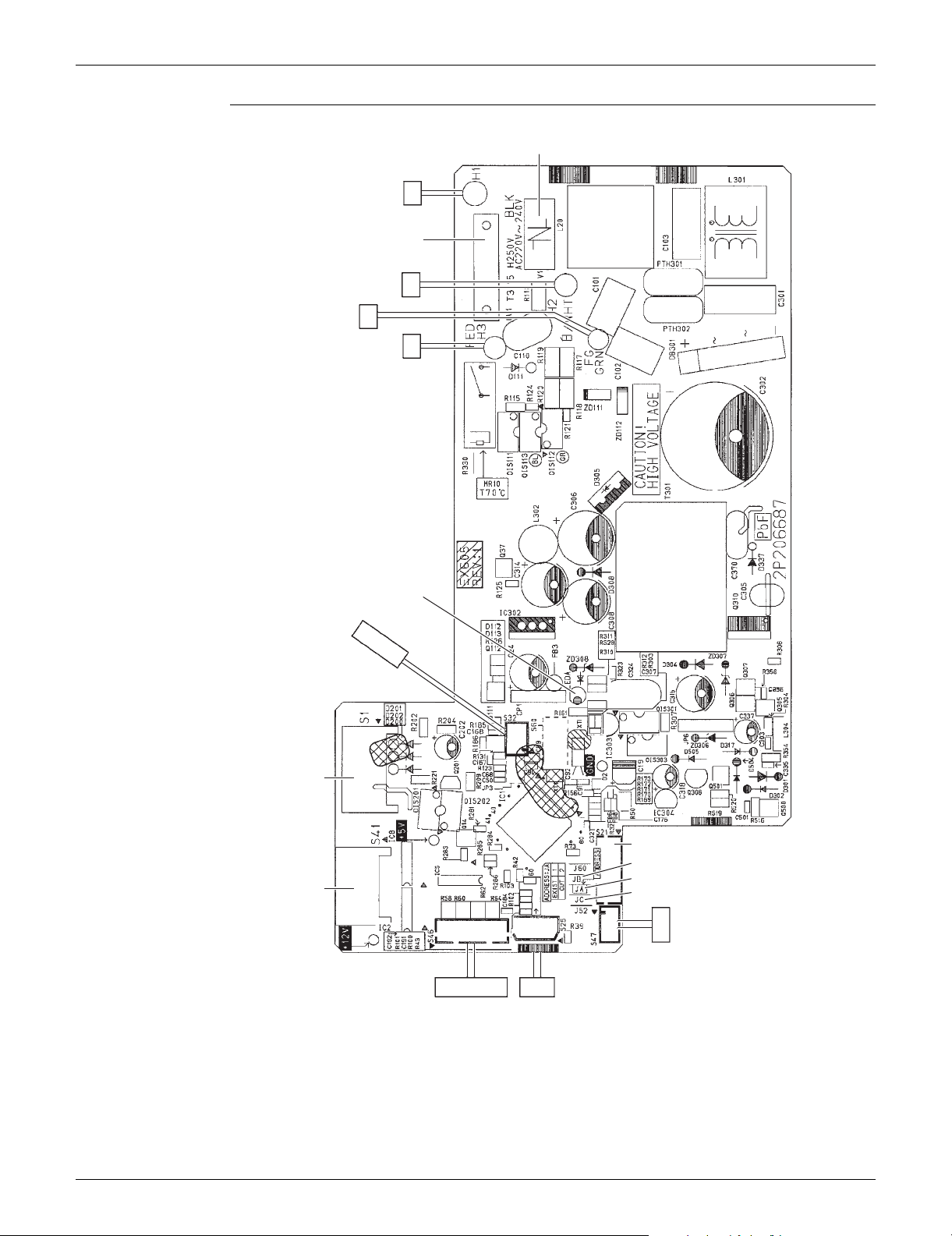
PCB Detail PCB (1): Control PCB
V1
H1
FU1
H2
FG
H3
S1
S41
S32
LED A
S46 S25
S21
JB
JA
JC
S47
2P206687-4
Printed Circuit Board Connector Wiring Diagram 14
Indoor Unit SiUS091133
3P210728-1
S48
RTH1
SW1
S49
LED3 LED2 LED1
3EB86013-1
S26
PCB (2): Signal Receiver PCB
PCB (3): Display PCB
3P210728-1
PCB (4): INTELLIGENT EYE Sensor PCB
15 Printed Circuit Board Connector Wiring Diagram

SiUS091133 Indoor Unit
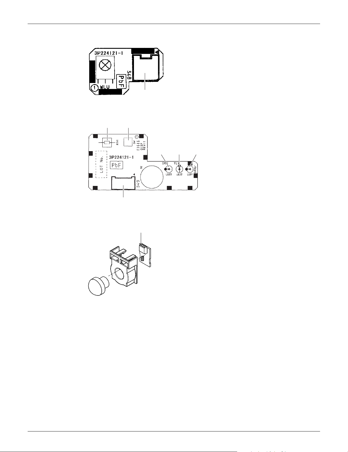
1.2 FTXS15/18/24/30/36LVJU
Connectors and
Other Parts
PCB (1): Control PCB
1) S1 Connector for DC fan motor
2) S21 Connector for centralized control (HA)
3) S25 Connector for INTELLIGENT EYE sensor PCB
4) S32 Indoor heat exchanger thermistor
5) S41 Connector for swing motors
6) S46 Connector for display PCB
7) S47 Connector for signal receiver PCB
8) H1, H2, H3, FG Connector for terminal board
9) JA Address setting jumper
Refer to page 388 for detail.
10)JB Fan speed setting when compressor stops for thermostat OFF
JC Power failure recovery function (auto-restart)
Refer to page 390 for detail.
11)LED A LED for service monitor (green)
12)FU1 (F1U) Fuse (3.15 A, 250 V)
13) V1 Varistor
PCB (2): Signal Receiver PCB
1) S48 Connector for control PCB
PCB (3): Display PCB
1) S49 Connector for control PCB
2) SW1 Forced cooling operation ON/OFF button
Refer to page 384 for detail.
3) LED1 (H1P) LED for operation (green)
4) LED2 (H2P) LED for timer (yellow)
5) LED3 (H3P) LED for INTELLIGENT EYE (green)
6) RTH1 (R1T) Room temperature thermistor
PCB (4): INTELLIGENT EYE Sensor PCB
1) S36 Connector for control PCB
Printed Circuit Board Connector Wiring Diagram 16
Indoor Unit SiUS091133
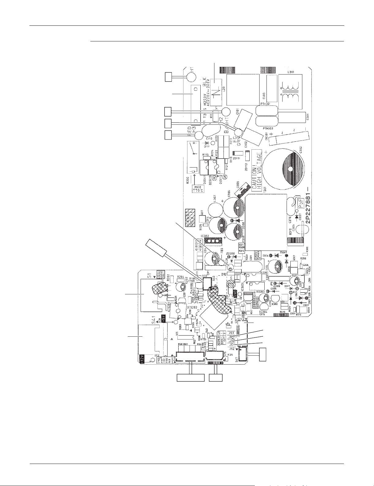
PCB Detail PCB (1): Control PCB
V1
H1
FU1
(3.15A)
H2
FG
H3
S1
S41
S32
LED A
S46 S25
S21
JB
JA
JC
S47
2P227881-5
2P227881-6
17 Printed Circuit Board Connector Wiring Diagram
SiUS091133 Indoor Unit
3P224121-1
S48
3P224121-1
RTH1 SW1
LED3
LED2
LED1
S49
S36
3P227885-1
PCB (2): Signal Receiver PCB
PCB (3): Display PCB
PCB (4): INTELLIGENT EYE Sensor PCB
Printed Circuit Board Connector Wiring Diagram 18

Indoor Unit SiUS091133
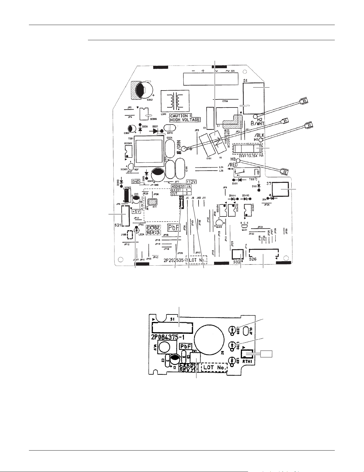
1.3 FDXS09/12LVJU
Connectors and
Other Parts
A1P: Control PCB
1) S1 Connector for AC fan motor
2) S7 Connector for AC fan motor (Hall IC)
3) S21 Connector for centralized control (HA)
4) S26 Connector for display PCB
5) S32 Connector for indoor heat exchanger thermistor
6) H1, H2, H3 Connector for terminal board
7) FG (GND) Connector for terminal board (ground)
8) JA Address setting jumper
Refer to page 388 for detail.
9) JB Fan speed setting when compressor stops for thermostat OFF
JC Power failure recovery function (auto-restart)
Refer to page 390 for detail.
10)LED A LED for service monitor (green)
11)FU1 (F1U) Fuse (3.15 A, 250 V)
12)V1 (V1TR) Varistor
A2P: Display PCB
1) S1 Connector for control PCB
2) SW1 (S1W) Forced cooling operation [ON/OFF] button
Refer to page 384 for detail.
3) LED2 (H2P) LED for timer (yellow)
4) LED3 (H3P) LED for operation (green)
5) RTH1 (R1T) Room temperature thermistor
19 Printed Circuit Board Connector Wiring Diagram
SiUS091133 Indoor Unit
H2
H1
H3
FG
JB
S21
2P292535-1
LED A JCJA
S7
S1
FU1
S26
V1
S32
S1
LED3
LED2
SW1
2P084375-1
RTH1
1
PCB Detail A1P: Control PCB
A2P: Display PCB
LED 1 does not function.
Printed Circuit Board Connector Wiring Diagram 20
 Loading...