

Daikin RXM90NVLT, RXM71NVLT, RXM80NVLT, RKS33JV2S, RKS85HVM Service Manual
...
REMOVAL
PROCEDURE
SERVICE MANUAL
Outdoor Unit
Inverter
Pair Type
6.0/7.0/7.1/8.0/8.5/9.0 kW Class
33000 Btu/h Class
Si001272EC

Service Manual
Removal Procedure
Outdoor Unit
zCooling Only zHeat Pump
RKM33NV2S RXM71NVLT
RXM80NVLT
RKS33JV2S RXM90NVLT
RKS85HVM RXS60KBVMA
RKS85JVMG RXS70MVLT
RXS80MVLT
RKS70MVLT RXS90MVLT
RKS80MVLT
RKS90MVLT
Si001272EC
Removal Procedure 1
Table of Contents
1. Outer Panels ...........................................................................................2
2. Electrical Box ..........................................................................................7
3. PCBs .....................................................................................................10
4. Fan Motor..............................................................................................12
5. Coils / Thermistors ................................................................................13
6. Sound Blankets.....................................................................................15
7. Compressor...........................................................................................16
Note:
The illustrations may be slightly different depending on the model.
The illustrations are for heat pump models as representative.
Outer Panels Si001272EC
2 Removal Procedure
1. Outer Panels
Warning
Be sure to wait for 10 minutes or more after turning off all power supplies before
disassembling work.
Step Procedure Points
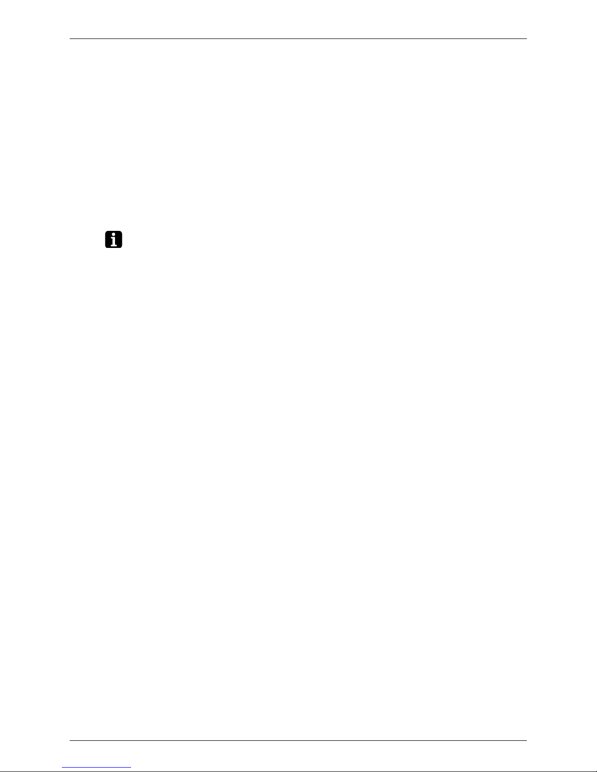
1. Remove the suction grille.
The hooks are secured in
the clearances of the
outdoor heat exchanger fins.
12Unfasten the 3 hooks at
the top.
Unfasten the 3 hooks at
the middle.
3 Unfasten the 3 hooks at
the bottom and remove
the suction grille.
2. Remove the top and right
side panels.
12Remove the 9 screws,
and then the top panel.
Remove the 5 screws
on the right side panel.
34Slide the right side
panel downward to
unfasten the 2 hooks on
the back side.
Remove the right side
panel.
(R16619)
Suction grille
(R9587)
Top panel
Right
side
panel
(R18690)
Hook
(R18072)
Si001272EC Outer Panels
Removal Procedure 3
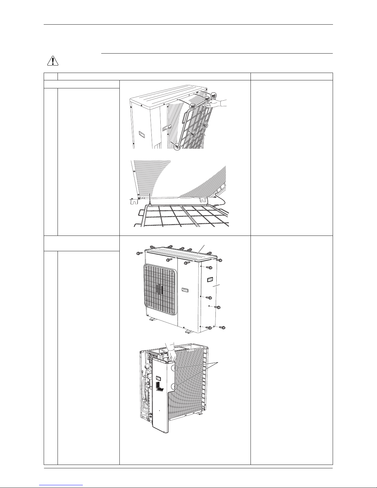
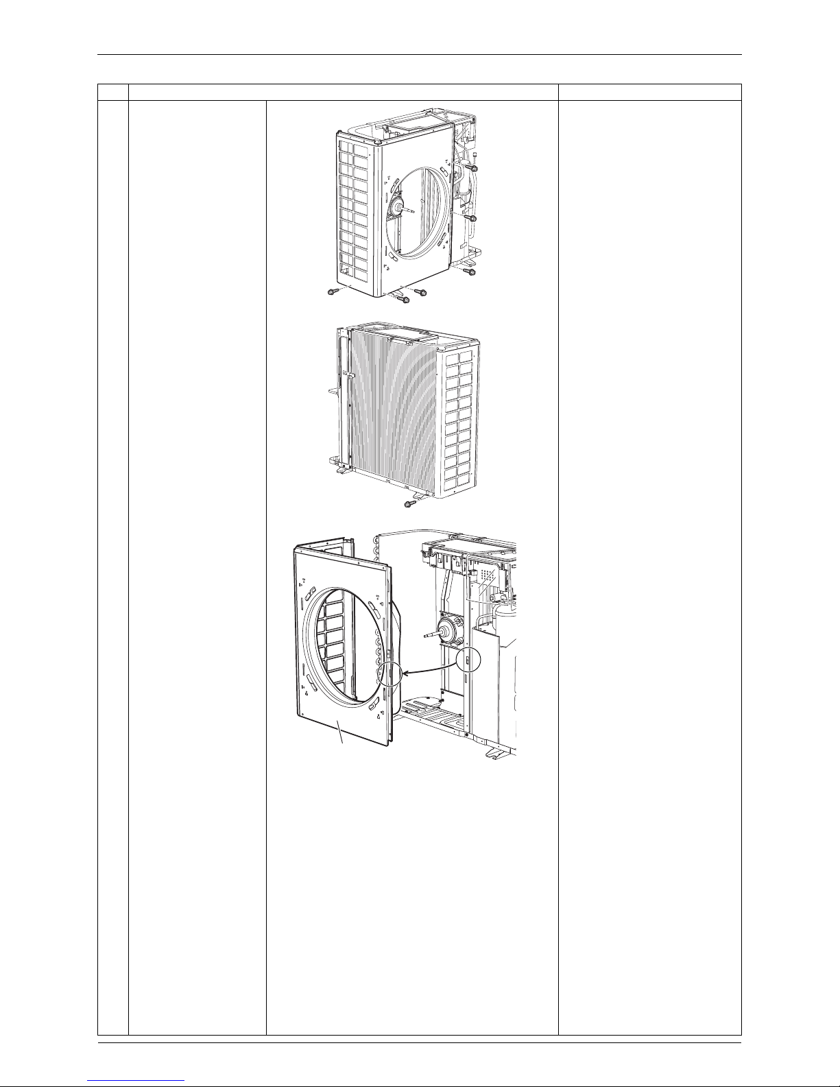
3. Remove the front panel
(2).
12Remove the screw.
Slide the front panel (2)
downward to unfasten
the 3 hooks.
3 Remove the front panel
(2).
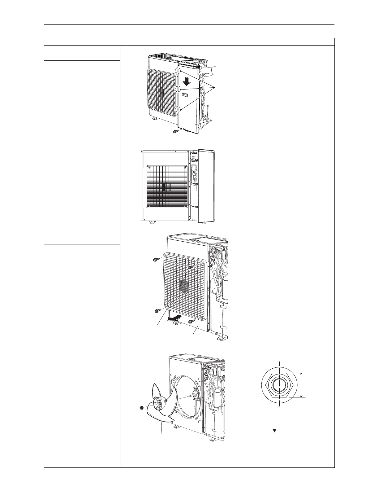
4. Remove the front panel
(1).
Remove the discharge grille
and the outdoor fan before
removing the front panel (1).
12Remove the 4 screws
on the discharge grille.
Pull the bottom of the
discharge grille and
remove it.
3 Remove the nut, and
then the outdoor fan.
Nut size: M8
When reassembling, align
the mark of the outdoor
fan with the D-cut section of
the motor shaft.
Step Procedure Points
Front
panel (2)
Hook
(R23986)
(R16718)
Discharge grille
Front panel (1)
(R18039)
(R18880)
Outdoor fan
13 mm
(0.51 inch)
(R18965)
Outer Panels Si001272EC
4 Removal Procedure
45Remove the 5 screws
on the front side.
Remove the screw at
the bottom of the left
side.
6 Remove the screw at
the bottom of the back
side.
7 Release the hook and
remove the front panel
(1).
Step Procedure Points
(R18040)
(R9602)
(R24010)
Front panel (1)
Si001272EC Outer Panels
Removal Procedure 5
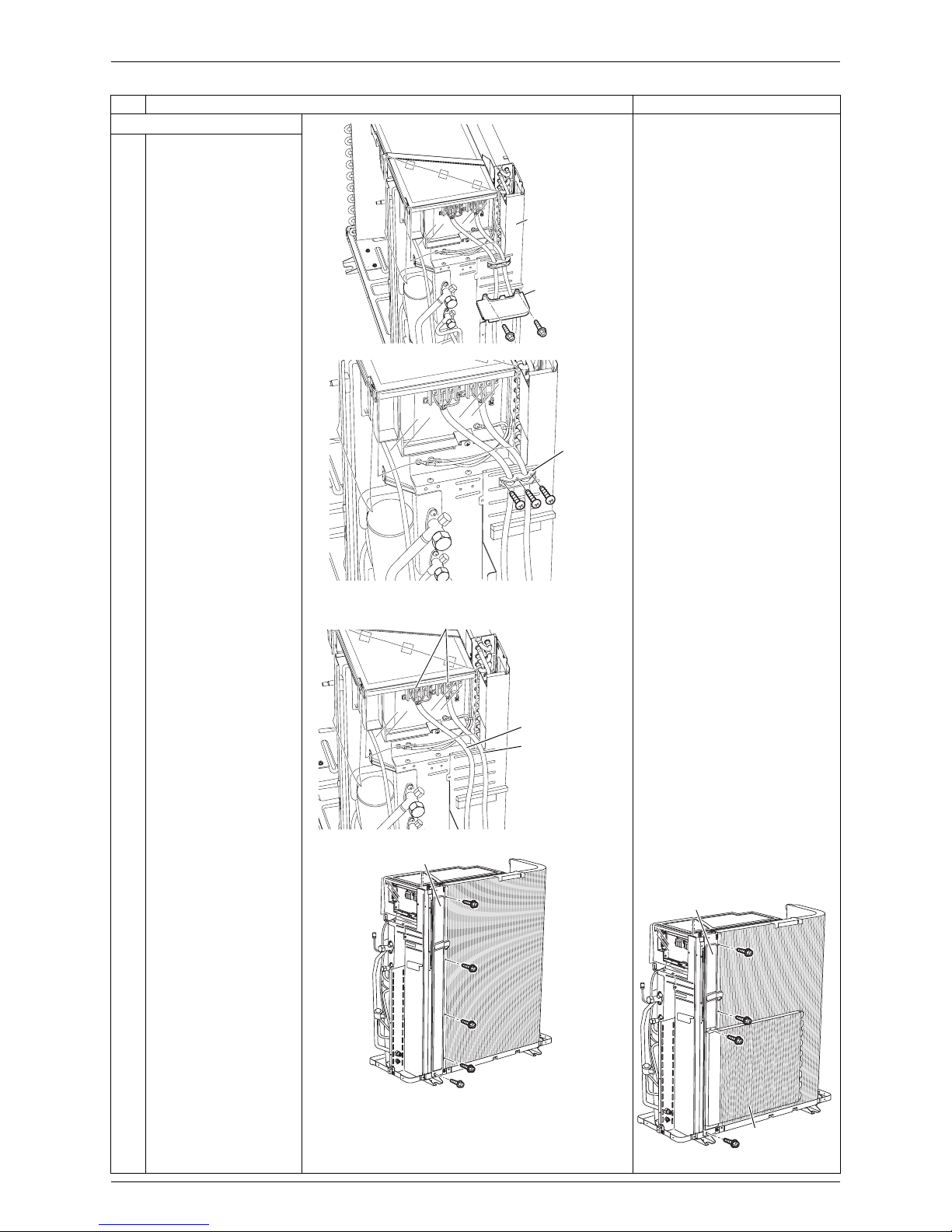
5. Remove the rear panel.
12Remove the 2 screws
on the partition plate
(2).
Lift up slightly and
remove the partition
plate (2).
3 Remove the 3 screws,
and then the wire
fixture.
45Remove the 7 screws
of the terminal block.
Detach the connecting
wire and the power
supply wire.
6
Remove the 5 screws.
When the unit has an
auxiliary heat exchanger,
remove the 4 screws.
Step Procedure Points
Rear panel
Partition
plate (2)
(R16720)
(R18882)
Wire
fixture
Connecting wire
Power supply wire
Terminal block
(R23987)
Rear panel
(R18043)
Rear panel
(R18883)
Auxiliary heat
exchanger
 Loading...