

Daikin RKS71FVMV, RKM28NV2S, RKS71GVM4, RKS71GVMV, RKS71HVM Service Manual
...
REMOVAL
PROCEDURE
SERVICE MANUAL
6.0/6.3/7.1 kW Class
24000/28000 Btu/h Class
Outdoor Unit
Inverter
Pair Type
Si001271EE

Service Manual
Removal Procedure
Outdoor Unit
zCooling Only zHeat Pump
RKM28NV2S RXM63NVLT
RKM71PVMG RXS60MVLT
RKS24JV2S RXS71FVMV
RKS28JV2S
RXS71FAV1B9
RKS60MVLT RXS71FAV1B8
RX71GV1B9
RKS71FVMV RX71GV1B8
RKS71GVM4 RXS71GVMV
RKS71GVMV
RXV71NVLT
RKS71HVM
RKS71JVMG
RKV71NVM
RKV71NVM4
RKV71NVMV

Si001271EE
Removal Procedure 1
Table of Contents
1. Outer Panels ...........................................................................................2
2. Electrical Box ..........................................................................................6
3. PCBs .......................................................................................................9
4. Fan Motor..............................................................................................11
5. Coils / Thermistors ................................................................................12
6. Sound Blankets.....................................................................................14
7. Compressor...........................................................................................15
Note:
The illustrations may be slightly different depending on the model.
The illustrations are for heat pump models as representative.

Outer Panels Si001271EE
2 Removal Procedure
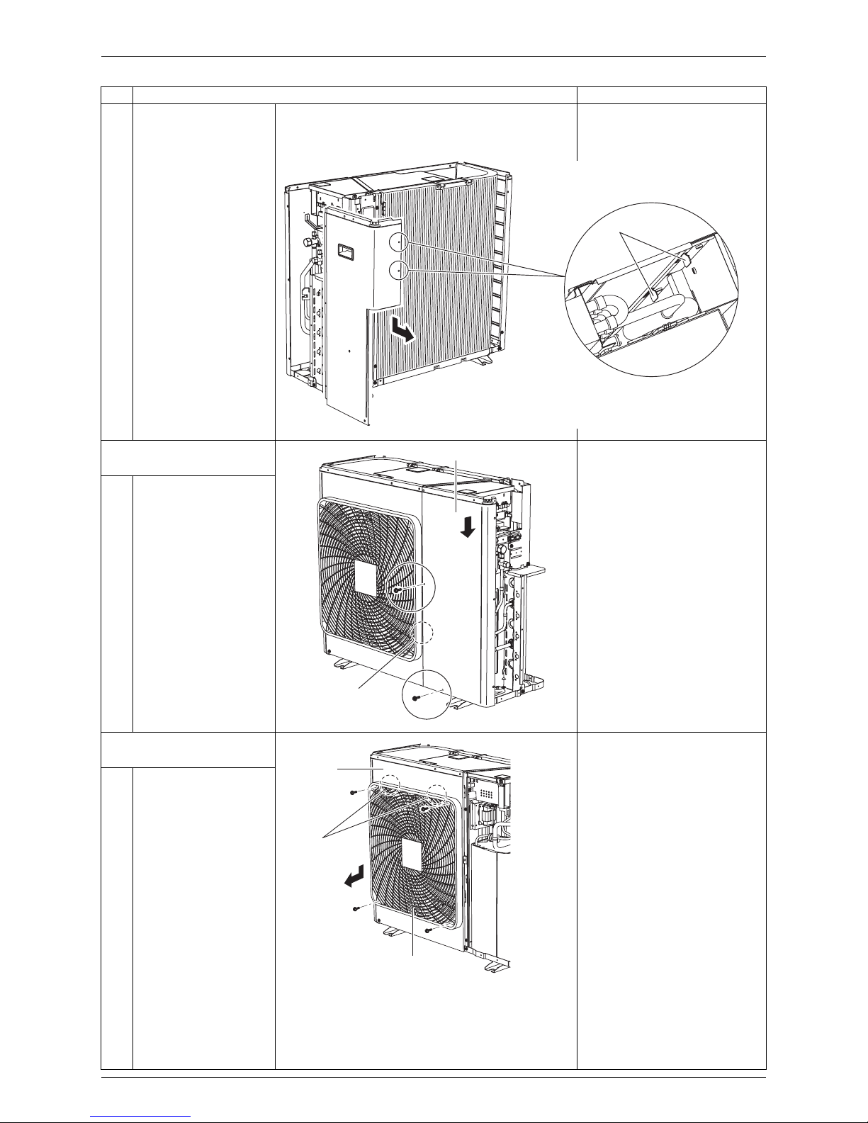
1. Outer Panels
Warning
Be sure to wait for 10 minutes or more after turning off all power supplies before
disassembling work.
Step Procedure Points
1. Remove the suction grille.
12Unfasten the 5 hooks.
Remove the suction
grille.
2. Remove the top panel.
The design of the discharge
grille varies depending on
the model.
12Remove the 8 screws.
Lift the top panel and
remove it.
3. Remove the right side
panel.
1 Remove the 5 screws.
(R17585)
Hook
Hook
Suction grille
(R18776)
Top panel
(R17071)
Right side panel
Si001271EE Outer Panels
Removal Procedure 3
2 Remove the right side
panel.
Slide the right side panel
downward to unfasten the 2
hooks on the rear side.
4. Remove the front panel
(2).
+
: This screw is M5(3) × 16.
Slide the front panel (2)
downward to unfasten the
hook.
1 Remove the 2 screws
and remove the front
panel (2).
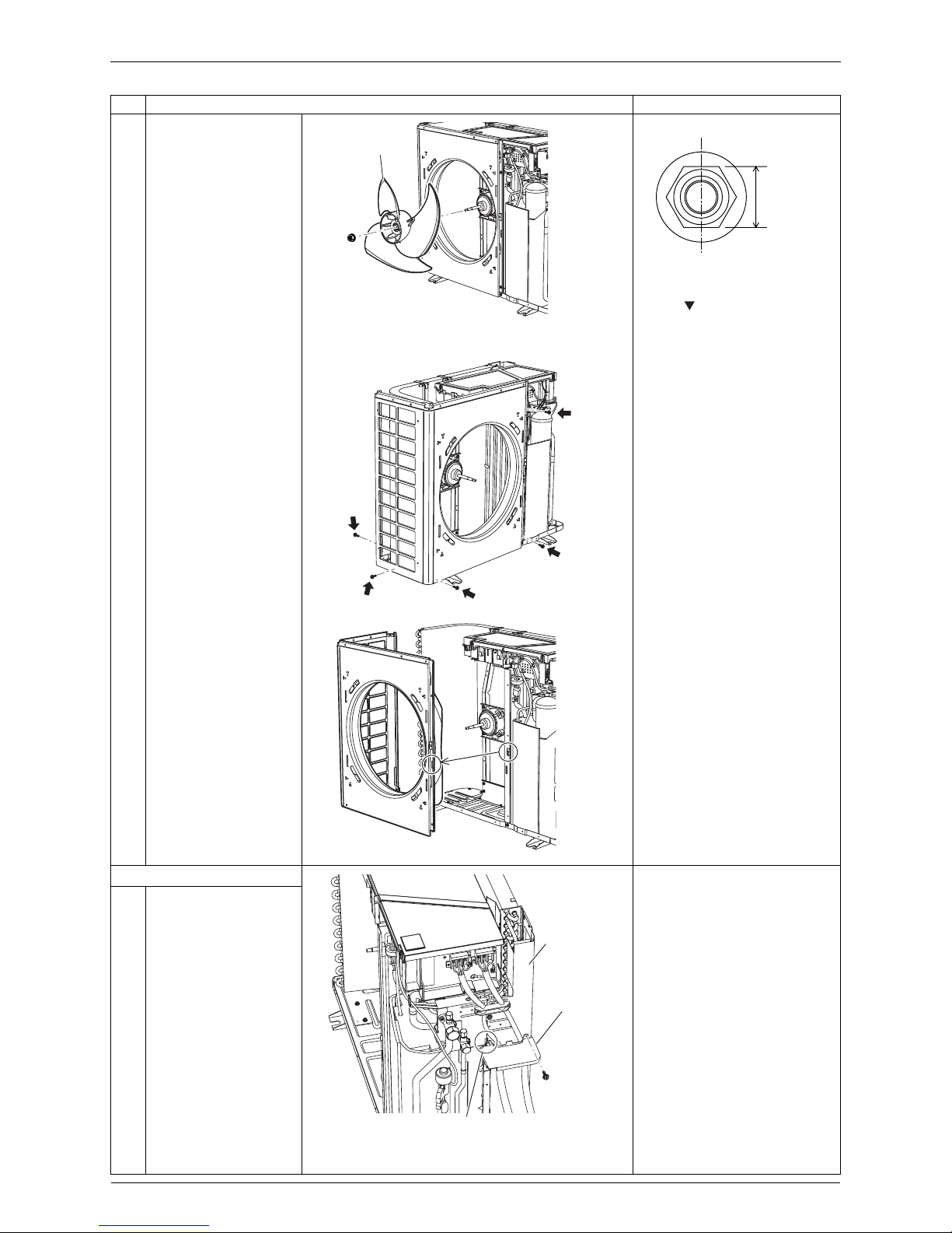
5. Remove the front panel
(1).
Remove the discharge grille
and the outdoor fan before
removing the front panel (1).
12Remove the 4 screws
on the discharge grille.
Unfasten the 2 hooks at
the top and remove the
discharge grille.
Step Procedure Points
(R17587)
Hook
(R18915)
Front Panel (2)
+
Hook
(R18916)
Discharge grille
Front
Panel (1)
Hook
Outer Panels Si001271EE
4 Removal Procedure
3 Remove the nut and
remove the outdoor fan.
Nut size: M8
When reassembling, align
the mark of the outdoor
fan with the D-cut section of
the motor shaft.
4 Remove the 5 screws.
5 Release the hook and
remove the front panel
(1).
6. Remove the rear panel.
When reassembling, make
sure that the hook is
securely fastened before
tightening the screw.
12Remove the screw on
the partition plate (2).
Unfasten the hook and
remove the partition
plate (2).
Step Procedure Points
Outdoor fan
(R16736)
13 mm
(0.51 inch)
(R18965)
(R18780)
(R17716)
Rear panel
Partition
plate (2)
Hook
(R17572)
 Loading...