

Daikin FTKM24PVMK, FTKM18PVMK, FTXM18PVMK, FTXM24PVMK, FTXM28PVMK Service Manual
...
Service
SiMT041509E
Manual
Inverter Pair
Wall Mounted Type
FTK(X)M-P Series
[Applied Models]
Inverter Pair : Heat Pump
z

zCooling Only
Indoor Unit
FTKM18PVMK
FTKM24PVMK
FTKM28PVMK
Outdoor Unit
SiMT041509E
Inverter Pair
Wall Mounted Type
FTK(X)M-P Series
RKM18PVMK
RKM24PVMK
RKM28PVMK
zHeat Pump
Indoor Unit
FTXM18PVMK
FTXM24PVMK
FTXM28PVMK
Outdoor Unit
RXM18PVMK
RXM24PVMK
RXM28PVMK
i Table of Contents

SiMT041509E
1. Safety Cautions.......................................................................................v
1.1 Warnings and Cautions Regarding Safety of Workers............................. v
1.2 Warnings and Cautions Regarding Safety of Users................................ xi
2. Used Icons ........................................................................................... xiv
Part 1 List of Functions ................................................................ 1
1. Functions.................................................................................................2
Part 2 Specifications .................................................................... 3
1. Specifications..........................................................................................4
Part 3 Printed Circuit Board Connector Wiring Diagram ............. 8
1. Indoor Unit...............................................................................................9
2. Outdoor Unit..........................................................................................11
Part 4 Function and Control........................................................12
1. Main Functions......................................................................................13
1.1 Temperature Control ..............................................................................13
1.2 Frequency Principle................................................................................13
1.3 Airflow Direction Control.........................................................................15
1.4 Fan Speed Control for Indoor Unit .........................................................16
1.5 Program Dry Operation ..........................................................................17
1.6 Automatic Operation...............................................................................18
1.7 Thermostat Control.................................................................................19
1.8 NIGHT SET Mode ..................................................................................20
1.9 ECONO Operation .................................................................................20
1.10 INTELLIGENT EYE Operation ...............................................................21
1.11 Inverter POWERFUL Operation .............................................................22
1.12 Clock Setting ..........................................................................................23
1.13 WEEKLY TIMER Operation ...................................................................24
1.14 Other Functions......................................................................................30
2. Function of Thermistor ..........................................................................31
3. Control Specification .............................................................................32
3.1 Mode Hierarchy ......................................................................................32
3.2 Frequency Control ..................................................................................33
3.3 Controls at Mode Changing / Start-up....................................................35
3.4 Discharge Pipe Temperature Control.....................................................36
3.5 Input Current Control ..............................................................................37
3.6 Freeze-up Protection Control .................................................................38
3.7 Heating Peak-cut Control .......................................................................38
3.8 Outdoor Fan Control...............................................................................39
3.9 Liquid Compression Protection Function................................................39
3.10 Defrost Control .......................................................................................40
3.11 Electronic Expansion Valve Control .......................................................41
3.12 Discharge Pipe Thermistor Disconnection Control.................................43
3.13 Malfunctions ...........................................................................................43
Table of Contents ii

SiMT041509E
Part 5 Remote Controller ............................................................44
1. Remote Controller .................................................................................45
Part 6 Service Diagnosis.............................................................47
1. General Problem Symptoms and Check Items .....................................48
2. Troubleshooting with LED.....................................................................49
2.1 Indoor Unit..............................................................................................49
2.2 Outdoor Unit ...........................................................................................49
3. Service Diagnosis .................................................................................50
4. Troubleshooting ....................................................................................53
4.1 Error Codes and Description ..................................................................53
4.2 Indoor Unit PCB Abnormality .................................................................54
4.3 Freeze-up Protection Control / Heating Peak-cut Control ......................55
4.4 Fan Motor (DC Motor) or Related Abnormality.......................................56
4.5 Thermistor or Related Abnormality (Indoor Unit)....................................58
4.6 Low-voltage Detection or Over-voltage Detection..................................59
4.7 Signal Transmission Error (Between Indoor Unit and Outdoor Unit)......61
4.8 Unspecified Voltage (Between Indoor Unit and Outdoor Unit) ...............63
4.9 Outdoor Unit PCB Abnormality...............................................................64
4.10 Actuation of High Pressure Switch .........................................................65
4.11 OL Activation (Compressor Overload) ...................................................66
4.12 Compressor Lock ...................................................................................68
4.13 DC Fan Lock ..........................................................................................69
4.14 Input Overcurrent Detection ...................................................................70
4.15 Four Way Valve Abnormality..................................................................71
4.16 Discharge Pipe Temperature Control.....................................................73
4.17 Compressor System Sensor Abnormality ..............................................74
4.18 Position Sensor Abnormality ..................................................................75
4.19 Thermistor or Related Abnormality (Outdoor Unit) .................................77
4.20 Electrical Box Temperature Rise ............................................................79
4.21 Radiation Fin Temperature Rise ............................................................80
4.22 Output Overcurrent Detection ................................................................81
5. Check ....................................................................................................83
5.1 Thermistor Resistance Check ................................................................83
5.2 Indoor Fan Motor Connector Output Check ...........................................84
5.3 Power Supply Waveforms Check...........................................................84
5.4 Electronic Expansion Valve Check.........................................................84
5.5 Four Way Valve Performance Check .....................................................85
5.6 Inverter Unit Refrigerant System Check.................................................85
5.7 Inverter Analyzer Check .........................................................................86
5.8 Rotation Pulse Check on the Outdoor Unit PCB ....................................87
5.9 Installation Condition Check ...................................................................88
5.10 Discharge Pressure Check.....................................................................88
5.11 Outdoor Fan System Check ...................................................................89
5.12 Main Circuit Short Check........................................................................89
5.13 Power Module Check .............................................................................90
Part 7 Trial Operation and Field Settings...................................91
1. Tips for Servicing ..................................................................................92
1.1 Pump Down Operation ...........................................................................92
iii Table of Contents

SiMT041509E
1.2 Forced Cooling Operation ......................................................................92
2. Trial Operation ......................................................................................93
3. Field Settings ........................................................................................94
3.1 When 2 Units are Installed in 1 Room....................................................94
3.2 Jumper Settings .....................................................................................94
4. Silicon Grease on Power Transistor / Diode Bridge..............................95
Part 8 Appendix...........................................................................96
1. Piping Diagrams....................................................................................97
1.1 Indoor Unit..............................................................................................97
1.2 Outdoor Unit ...........................................................................................98
2. Wiring Diagrams..................................................................................101
2.1 Indoor Unit............................................................................................101
2.2 Outdoor Unit .........................................................................................102
Table of Contents iv
Safety Cautions SiMT041509E
1. Safety Cautions
Be sure to read the following safety cautions before conducting repair work.
After the repair work is complete, be sure to conduct a test operation to ensure that the
equipment operates normally, and explain the cautions for operating the product to the
customer.
Caution Items The caution items are classified into Warning and Caution. The Warning items are
especially important since they can lead to death or serious injury if they are not followed
closely. The Caution items can also lead to serious accidents under some conditions if they
are not followed. Therefore, be sure to observe all the safety caution items described below.
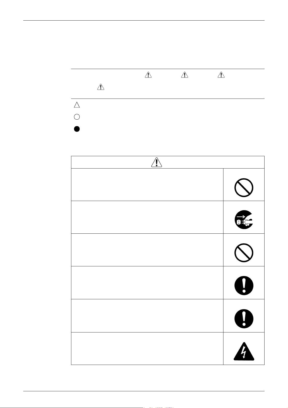
Pictograms This symbol indicates the item for which caution must be exercised.
The pictogram shows the item to which attention must be paid.
This symbol indicates the prohibited action.
The prohibited item or action is shown in the illustration or near the symbol.
This symbol indicates the action that must be taken, or the instruction.
The instruction is shown in the illustration or near the symbol.
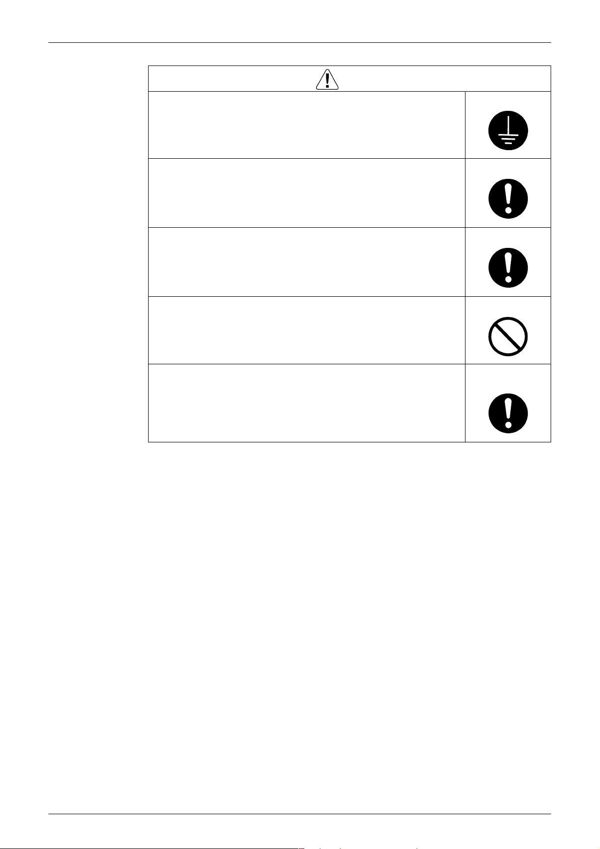
1.1 Warnings and Cautions Regarding Safety of Workers
Warning
Do not store the equipment in a room with successive fire sources (e.g.,
naked flame, gas appliance, electric heater).
Be sure to disconnect the power cable plug from the plug socket before
disassembling the equipment for repair.
Working on the equipment that is connected to the power supply may cause an
electrical shock.
If it is necessary to supply power to the equipment to conduct the repair or
inspecting the circuits, do not touch any electrically charged sections of the
equipment.
If the refrigerant gas is discharged during the repair work, do not touch
the discharged refrigerant gas.
The refrigerant gas may cause frostbite.
When disconnecting the suction or discharge pipe of the compressor at
the welded section, evacuate the refrigerant gas completely at a wellventilated place first.
If there is gas remaining inside the compressor, the refrigerant gas or
refrigerating machine oil discharges when the pipe is disconnected, and it may
cause injury.
If the refrigerant gas leaks during the repair work, ventilate the area.
The refrigerant gas may generate toxic gases when it contacts flames.
Be sure to discharge the capacitor completely before conducting repair
work.
The step-up capacitor supplies high-voltage electricity to the electrical
components of the outdoor unit.
A charged capacitor may cause an electrical shock.
v
SiMT041509E Safety Cautions
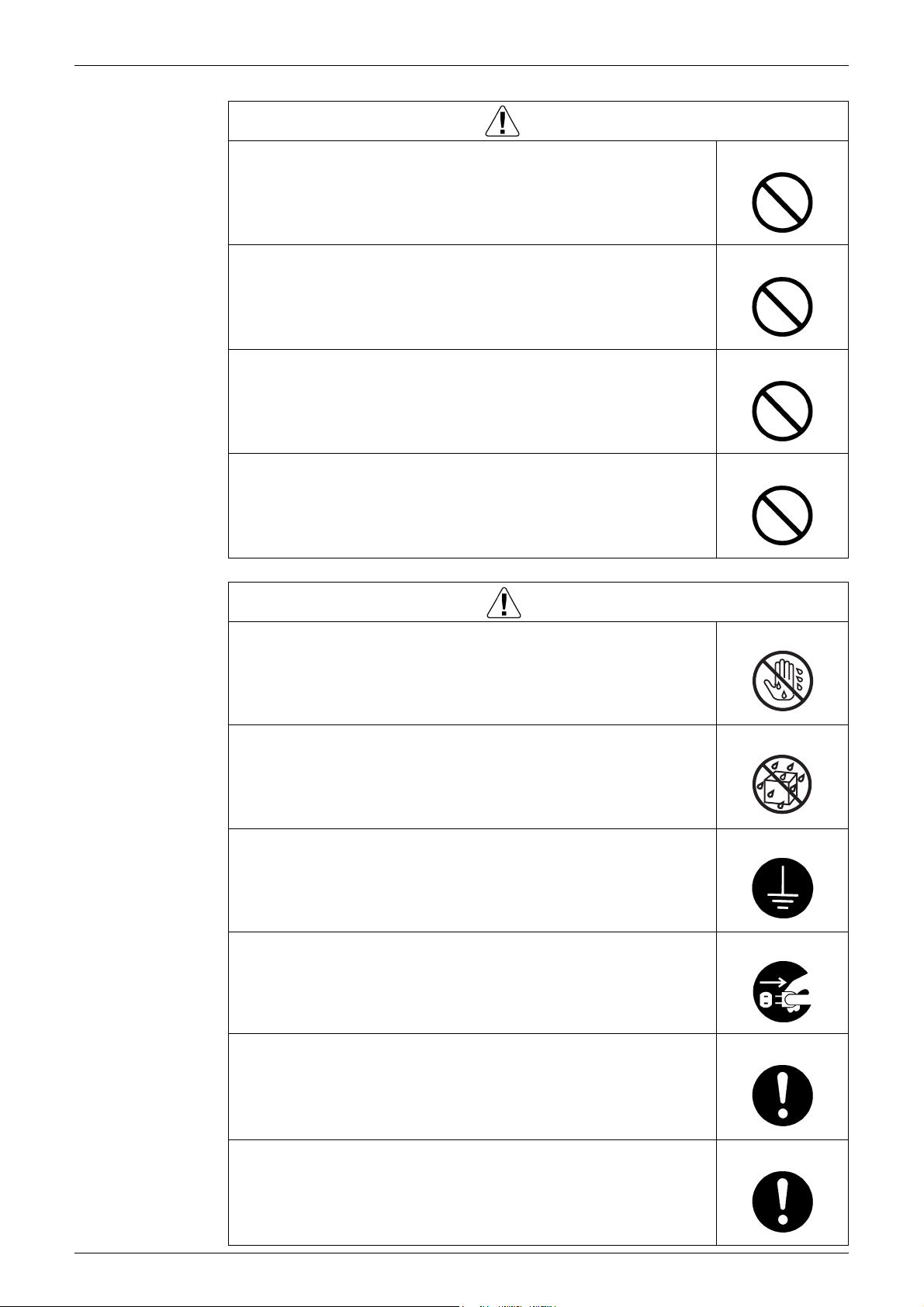
Warning
Do not start or stop the air conditioner operation by plugging or
unplugging the power cable plug.
Plugging or unplugging the power cable plug to operate the equipment may
cause an electrical shock or fire.
Be sure to wear a safety helmet, gloves, and a safety belt when working
at a high place (more than 2 m).
Insufficient safety measures may cause a fall accident.
In case of R-32 / R-410A refrigerant models, be sure to use pipes, flare
nuts and tools for the exclusive use of the R-32 / R-410A refrigerant.
The use of materials for R-22 refrigerant models may cause a serious accident
such as a damage of refrigerant cycle as well as an equipment failure.
Do not mix air or gas other than the specified refrigerant (R-32 / R-410A /
R-22) in the refrigerant system.
If air enters the refrigerating system, an excessively high pressure results,
causing equipment damage and injury.
Caution
Do not repair the electrical components with wet hands.
Working on the equipment with wet hands may cause an electrical shock.
Do not clean the air conditioner by splashing water.
Washing the unit with water may cause an electrical shock.
Be sure to provide the earth / grounding when repairing the equipment in
a humid or wet place, to avoid electrical shocks.
Be sure to turn off the power switch and unplug the power cable when
cleaning the equipment.
The internal fan rotates at a high speed, and may cause injury.
Be sure to conduct repair work with appropriate tools.
The use of inappropriate tools may cause injury.
Be sure to check that the refrigerating cycle section has cooled down
enough before conducting repair work.
Working on the unit when the refrigerating cycle section is hot may cause
burns.
vi

Safety Cautions SiMT041509E
Caution
Use the welder in a well-ventilated place.
Using the welder in an enclosed room may cause oxygen deficiency.
Checking the area
Before beginning work, conduct safety checks to minimise the risk of ignition. When repairing
the refrigerating system, take the following precautions before work.
Work procedure
Work shall be conducted under a controlled procedure so as to minimise the risk of working in
the presence of R-32 or vapour.
General working area
All maintenance staff and others working in the local area shall be instructed on the nature of
work being carried out.
Work in confined spaces shall be avoided.
The area around the workspace shall be sectioned off. Ensure that the conditions within the
area have been made safe by control of flammable materials.
Checking for presence of refrigerant
The working area shall be checked with an appropriate refrigerant detector before and during
work, to ensure the technician is aware of potentially flammable atmospheres.
Ensure that the leak detection equipment being used is suitable for use with R-32, i.e. nonsparking, adequately sealed or intrinsically safe.
Fire extinguishing equipment
If any hot work is to be conducted on the refrigeration equipment or any associated parts,
appropriate fire extinguishing equipment shall be made available at hand. Prepare a dry powder
fire extinguisher adjacent to the working area.
2
or CO
No ignition sources
During work on a refrigeration system which involves exposing any piping work that contains or
has contained R-32, any sources of ignition shall not be used in a manner that may lead to the
risk of fire or explosion. All possible ignition sources, including cigarette smoking, should be
kept at a safe distance from the site of installation, repairing, or removing space. Before starting
work, the area around the equipment shall be examined to make sure that there are no
flammable hazard or ignition risks. No Smoking signs shall be displayed.
Ventilated area
Ensure that the working area is open or that it is adequately ventilated before work.
Adequate ventilation shall be maintained during the entire period of work.
The ventilation should disperse any released refrigerant and preferably discharge it into the
external atmosphere.
vii

SiMT041509E Safety Cautions
Checking the refrigeration equipment
Where electrical components are to be changed, the new components shall be fit for the
purpose and have the correct specifications.
The manufacturer's maintenance and service guidelines shall be followed at all times.
If there are any unclear points, consult the manufacturer's technical department for assistance.
The following checks shall be applied to any installation work involving R-32:
• The amount of charge is in accordance with the size of the room where the refrigerant
containing parts are installed;
• The ventilation machinery and outlets are operating adequately and are not obstructed;
• If an indirect refrigerating circuit is being used, the secondary circuit shall be checked for
the presence of refrigerant;
• Marking on the equipment is visible and legible. Markings and signs that are illegible shall
be corrected;
• Refrigeration pipes or components are installed in a position where they are unlikely to be
exposed to any substance which may corrode refrigerant containing components, or the
refrigerant containing components are constructed of materials which are inherently
resistant to corrosion or are suitably protected against corrosion.
Checking electrical devices
Repair and maintenance to electrical components shall include initial safety checks and
component inspection procedures. In case there is any fault that could endanger safety, no
electrical supply shall be connected to the circuit until the fault is satisfactorily dealt with.
Initial safety checks shall include:
• that capacitors are discharged: this shall be done in a safe manner to avoid possibility of
sparking;
• that no live electrical components and wiring are exposed while charging, recovering or
purging the system;
• that the equipment is earthed at all times.
Repairs to sealed components
During repairs to sealed components, all electrical supplies shall be disconnected from the
equipment being worked upon before the removal of any sealed covers, etc. If it is absolutely
necessary to have power supplied to equipment during servicing, continuously operating leak
detection shall be installed at the most dangerous point of the system in order to warn of a
potentially hazardous situation.
Particular attention shall be paid to the following: ensure that working on electrical components
does not alter the casing in such a way that affects the level of protection including damage to
cables, excessive number of connections, terminals different from the original specification,
damage to seals, incorrect fitting of glands, etc.
Ensure that the equipment is mounted securely.
Ensure that seals or sealing materials have not degraded such that they no longer serve the
purpose of preventing the ingression of flammable atmospheres. Replacement parts shall be in
accordance with the manufacturer's specifications.
The use of silicon sealant may inhibit the effectiveness of some types of leak detection
equipment. Intrinsically safe components do not have to be isolated before working on them.
Repair to intrinsically safe components
Do not apply any permanent inductive or capacitance load to the circuit without ensuring that
this will not exceed the permissible voltage and current for the equipment in use.
Only intrinsically safe components can be worked on in the presence of a flammable
atmosphere.
The test apparatus shall be of correct rating.
Replace components only with parts specified by the manufacturer. Using other parts may
result in ignition of the refrigerant leaked into the atmosphere.
Wiring
Check that wiring is not subject to wear, corrosion, excessive pressure, vibration, sharp edges
or any other adverse environmental effects. The check shall also take into account the effects of
ageing or continuous vibration from sources such as compressors or fans.
viii

Safety Cautions SiMT041509E
Detecting of R-32
Under no circumstances shall potential sources of ignition be used in the search for or detection
of refrigerant leaks. A halide torch (or any other detector using a naked flame) shall not be used.
Leak detection methods
The following leak detection methods can be applied for systems containing R-32.
Electronic leak detectors shall be used to detect R-32, but the sensitivity may not be adequate
or may need re-calibration (detection equipment shall be calibrated in a refrigerant-free area).
Ensure that the detector is not a potential source of ignition and that it is suitable for the
refrigerant used. Leak detection equipment shall be set to the percentage of the lower
flammability limit (LFL) of the refrigerant and calibrated to fit the refrigerant employed. The
appropriate percentage of gas (maximum 25%) shall be confirmed.
Leak detection fluids are suitable for use with most refrigerants but the use of detergents
containing chlorine shall be avoided as the chlorine may react with the refrigerant and corrode
the copper piping work.
If a leak is suspected, all naked flames shall be removed or extinguished.
If a refrigerant leakage which requires brazing is found, all of the refrigerant shall be recovered
from the system, or isolated (by means of shut off valves) in a part of the system remote from
the point of the leakage. Oxygen free nitrogen (OFN) shall then be purged through the system
both before and during the brazing process.
Removal and evacuation
When breaking the refrigerant circuit to make repairs or any other purpose, conventional
procedures may be used. However, flammability must be taken into consideration. The
following procedure shall be adhered to:
• Remove refrigerant;
• Purge the circuit with inert gas;
• Evacuate the inert gas;
• Purge again with inert gas;
• Carry out cutting or brazing of the circuit.
The refrigerant shall be recovered into the correct recovery cylinders. The system shall be
cleaned with OFN to render the unit safe. (= Flushing) This process may need to be repeated
several times. Compressed air or oxygen shall not be used for this task.
Flushing shall be achieved through breaking the vacuum by filling the system with OFN until the
working pressure is achieved, then venting the OFN into the atmosphere, and finally pulling the
system down to vacuum again. This process shall be repeated until no refrigerant remains
within the system. After the last OFN charge is finished, the system shall be vented down to
atmospheric pressure to enable work. This operation is especially important if brazing
operations on the piping work are to take place.
Ensure that the outlet for the vacuum pump is not close to any ignition sources and that there is
ventilation available.
Charging procedures
In addition to conventional charging procedures, the following requirements shall be met.
Ensure that the charging equipment to be used is not contaminated by different refrigerants.
Hoses or lines shall be as short as possible to minimise the amount of refrigerant contained in
them.
• Cylinders shall be kept upright.
• Ensure that the refrigeration system is earthed before charging the system with refrigerant.
• Label the system when charging is complete (if not already).
• Extreme care shall be taken not to overfill the refrigeration system.
Before recharging, the system shall be tested for leakage with OFN. On completion of charging,
the system shall be tested before commissioning. Follow up leakage test shall be carried out
before leaving the site.
ix

SiMT041509E Safety Cautions
Decommissioning
Before carrying out this procedure, it is essential that the technician is completely familiar with
the equipment and all its details. It is recommended to train technicians so that all of the
refrigerant is recovered safely. In case analysis is required before re-using the reclaimed
refrigerant, an oil and refrigerant sample shall be taken before proceeding with
decommissioning. It is essential that electrical power is available before work.
a) Comprehend the equipment and its operation.
b) Isolate the system electrically.
c) Before starting work, ensure that:
• mechanical handling equipment is available if required, for handling refrigerant cylinders;
• protective equipment can be used in compliance with specifications;
• the recovery process is supervised by a competent person at all times;
• recovery equipment and cylinders conform to the appropriate standards.
d) Pump down the refrigerant system, if possible.
e) If vacuum can not be ensured, apply a manifold so that refrigerant can be removed from
various parts of the system.
f) Make sure that the cylinder is situated on the scale before recovery takes place.
g) Start the refrigerant recovery device and operate it in accordance with the manufacturer's
instructions.
h) Do not overfill cylinders. (Do not exceed 80% liquid charge volume).
i) Do not exceed the maximum working pressure of the cylinder, even temporarily.
j) When the cylinders have been filled correctly and the process is completed, make sure
that the cylinders and the equipment are removed from site promptly and all valves on the
equipment are closed.
k) Recovered refrigerant shall not be charged into another refrigeration system before it has
been cleaned and checked.
Labelling
Equipment shall be labelled stating that it has been decommissioned and emptied of refrigerant.
The label shall be dated and signed. Ensure that there are labels on the equipment stating the
equipment contains R-32.
Refrigerant recovery
When removing refrigerant from a system, either for servicing or decommissioning, it is
recommended to conduct training so that all refrigerants can be removed safely.
When transferring refrigerant into cylinders, ensure that only appropriate refrigerant recovery
cylinders are used.
Ensure that the correct number of cylinders for holding the total system charge are available. All
cylinders to be used must be designated for the recovered refrigerant and labelled for that
refrigerant (i.e. special cylinders for the recovery of refrigerant). Cylinders shall be equipped
with a pressure relief valve and associated shut-off valves in good working order. If possible,
empty recovery cylinders shall be cooled in a separate place before recovery is conducted.
The recovery equipment shall be in good working order with instructions concerning the
equipment at hand, and shall be suitable for the recovery of R-32. In addition, a set of calibrated
weighing scales shall be available and in good working order. Hoses shall be equipped with
leak-free disconnect couplings and in good condition. Before using the recovery device, check
that it has undergone proper maintenance, that it is in satisfactory working order, and that any
associated electrical components are sealed to prevent ignition in the event of a refrigerant
leakage. Consult manufacturer if in doubt.
The recovered refrigerant shall be returned to the refrigerant supplier in the correct recovery
cylinder, with the relevant Waste Transfer Note attached. Do not mix refrigerants in recovery
units and especially not in cylinders.
If compressors or compressor oil are to be removed, ensure that the refrigerant melted into the
oil has been evacuated to an acceptable level to make certain that R-32 does not remain within
the oil. The evacuation process shall be carried out before returning the compressor to the
supplier. Only electric heating to the compressor body shall be employed to accelerate this
process. Oil drained from the system shall be treated safely.
x
Safety Cautions SiMT041509E
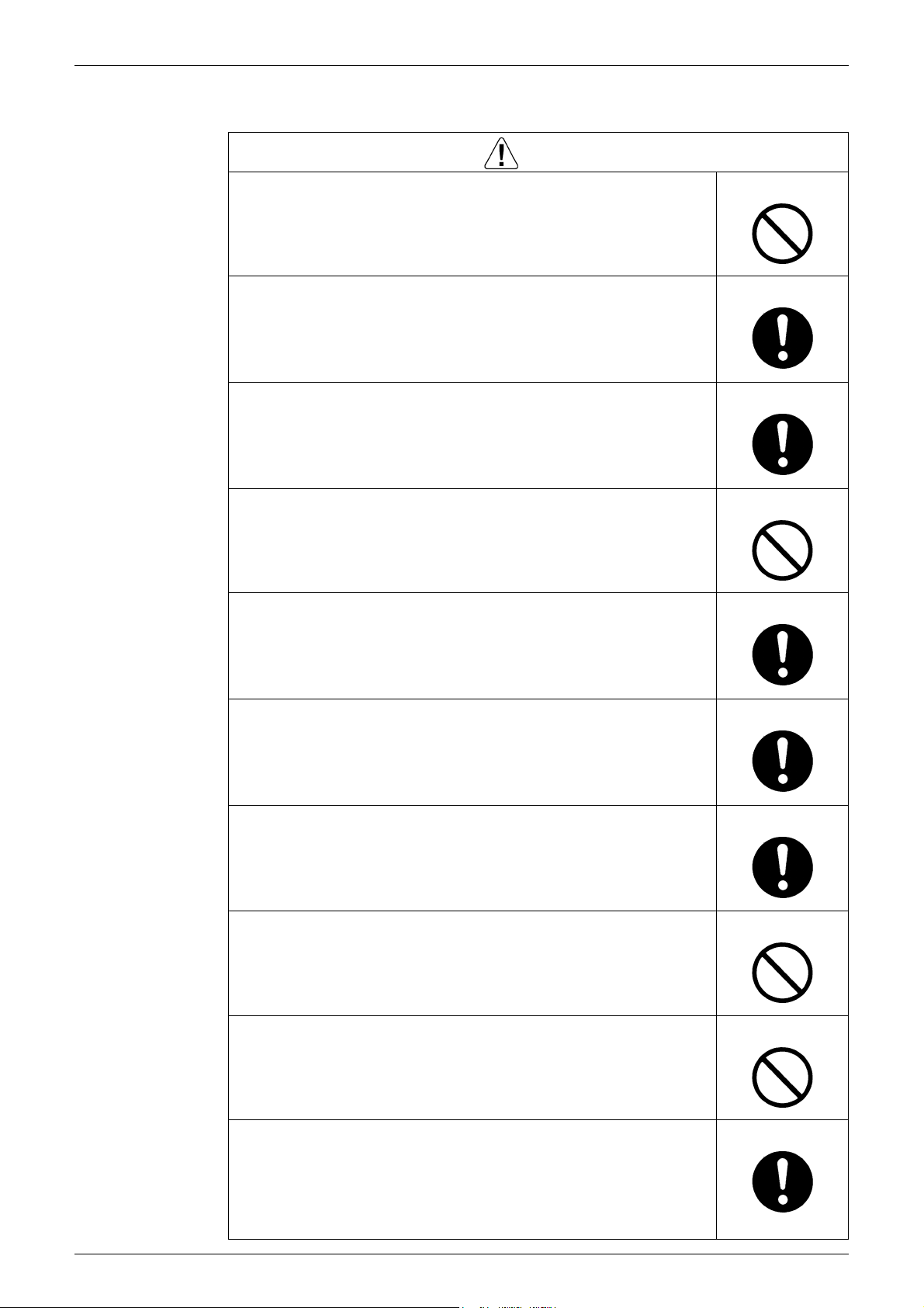
1.2 Warnings and Cautions Regarding Safety of Users
Warning
Do not store the equipment in a room with successive fire sources (e.g.,
naked flame, gas appliance, electric heater).
Be sure to use parts listed in the service parts list of the applicable model
and appropriate tools to conduct repair work. Never attempt to modify the
equipment.
The use of inappropriate parts or tools may cause an electrical shock,
excessive heat generation or fire.
If the power cable and lead wires have scratches or deteriorated, be sure
to replace them.
Damaged cable and wires may cause an electrical shock, excessive heat
generation or fire.
Do not use a joined power cable or extension cable, or share the same
power outlet with other electrical appliances, since it may cause an
electrical shock, excessive heat generation or fire.
Be sure to use an exclusive power circuit for the equipment, and follow
the local technical standards related to the electrical equipment, the
internal wiring regulations, and the instruction manual for installation
when conducting electrical work.
Insufficient power circuit capacity and improper electrical work may cause an
electrical shock or fire.
Be sure to use the specified cable for wiring between the indoor and
outdoor units.
Make the connections securely and route the cable properly so that there is no
force pulling the cable at the connection terminals.
Improper connections may cause excessive heat generation or fire.
When wiring between the indoor and outdoor units, make sure that the
terminal cover does not lift off or dismount because of the cable.
If the cover is not mounted properly, the terminal connection section may cause
an electrical shock, excessive heat generation or fire.
Do not damage or modify the power cable.
Damaged or modified power cable may cause an electrical shock or fire.
Placing heavy items on the power cable, and heating or pulling the power cable
may damage the cable.
Do not mix air or gas other than the specified refrigerant (R-32 / R-410A /
R-22) in the refrigerant system.
If air enters the refrigerating system, an excessively high pressure results,
causing equipment damage and injury.
If the refrigerant gas leaks, be sure to locate the leaking point and repair
it before charging the refrigerant. After charging refrigerant, make sure
that there is no refrigerant leak.
If the leaking point cannot be located and the repair work must be stopped, be
sure to perform pump-down and close the service valve, to prevent the
refrigerant gas from leaking into the room. The refrigerant gas itself is
harmless, but it may generate toxic gases when it contacts flames, such as fan
and other heaters, stoves and ranges.
xi
SiMT041509E Safety Cautions
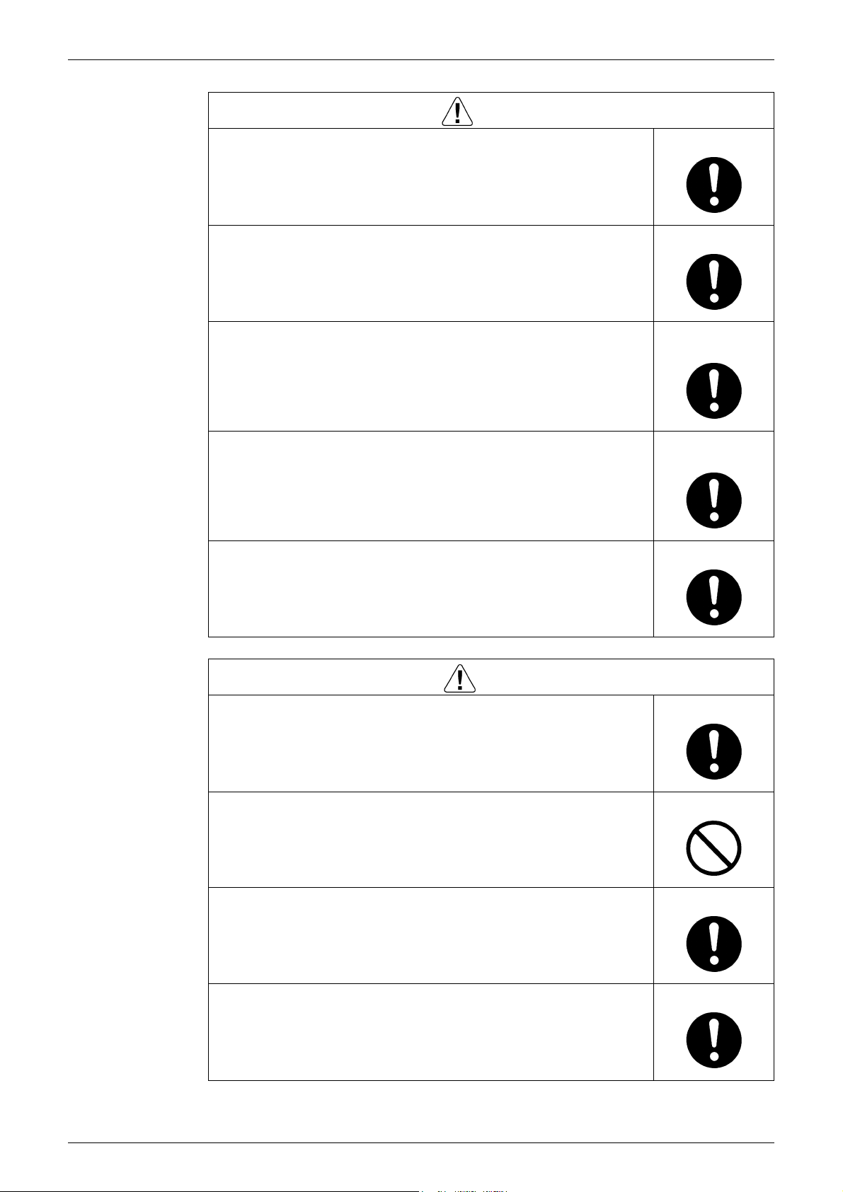
Warning
When relocating the equipment, make sure that the new installation site
has sufficient strength to withstand the weight of the equipment.
If the installation site does not have sufficient strength and if the installation
work is not conducted securely, the equipment may fall and cause injury.
Check to make sure that the power cable plug is not dirty or loose, then
insert the plug into a power outlet securely.
If the plug has dust or loose connection, it may cause an electrical shock or fire.
Be sure to install the product correctly by using the provided standard
installation frame.
Incorrect use of the installation frame and improper installation may cause the
equipment to fall, resulting in injury.
Be sure to install the product securely in the installation frame mounted
on the window frame.
If the unit is not securely mounted, it may fall and cause injury.
When replacing the coin battery in the remote controller, be sure to
dispose of the old battery to prevent children from swallowing it.
If a child swallows the coin battery, see a doctor immediately.
Caution
Installation of a leakage breaker is necessary in some cases depending
on the conditions of the installation site, to prevent electrical shocks.
For unitary type
only
For unitary type
only
Do not install the equipment in a place where there is a possibility of
combustible gas leaks.
If the combustible gas leaks and remains around the unit, it may cause a fire.
Check to see if the parts and wires are mounted and connected properly,
and if the connections at the soldered or crimped terminals are secure.
Improper installation and connections may cause excessive heat generation,
fire or an electrical shock.
If the installation platform or frame has corroded, replace it.
Corroded installation platform or frame may cause the unit to fall, resulting in
injury.
xii
Safety Cautions SiMT041509E
Caution
Check the earth / grounding, and repair it if the equipment is not properly
earthed / grounded.
Improper earth / grounding may cause an electrical shock.
Be sure to measure the insulation resistance after the repair, and make
sure that the resistance is 1 MΩ or higher.
Faulty insulation may cause an electrical shock.
Be sure to check the drainage of the indoor unit after the repair.
Faulty drainage may cause the water to enter the room and wet the furniture
and floor.
Do not tilt the unit when removing it.
The water inside the unit may spill and wet the furniture and floor.
Be sure to install the packing and seal on the installation frame properly.
If the packing and seal are not installed properly, water may enter the room and
wet the furniture and floor.
For unitary type
only
xiii
SiMT041509E Used Icons
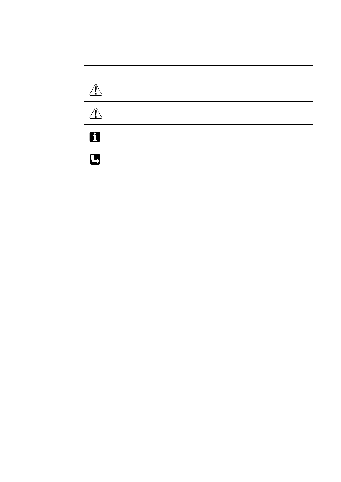
2. Used Icons
The following icons are used to attract the attention of the reader to specific information.
Icon Type of
Information
Warning A Warning is used when there is danger of personal injury.
Warning
Caution A Caution is used when there is danger that the reader, through
Caution
Note A Note provides information that is not indispensable, but may
Note:
Reference A Reference guides the reader to other places in this binder or
Description
incorrect manipulation, may damage equipment, lose data, get
an unexpected result or has to restart (part of) a procedure.
nevertheless be valuable to the reader, such as tips and tricks.
in this manual, where he/she will find additional information on a
specific topic.
xiv

SiMT041509E
Part 1
List of Functions
1. Functions.................................................................................................2
1 List of Functions
SiMT041509E Functions
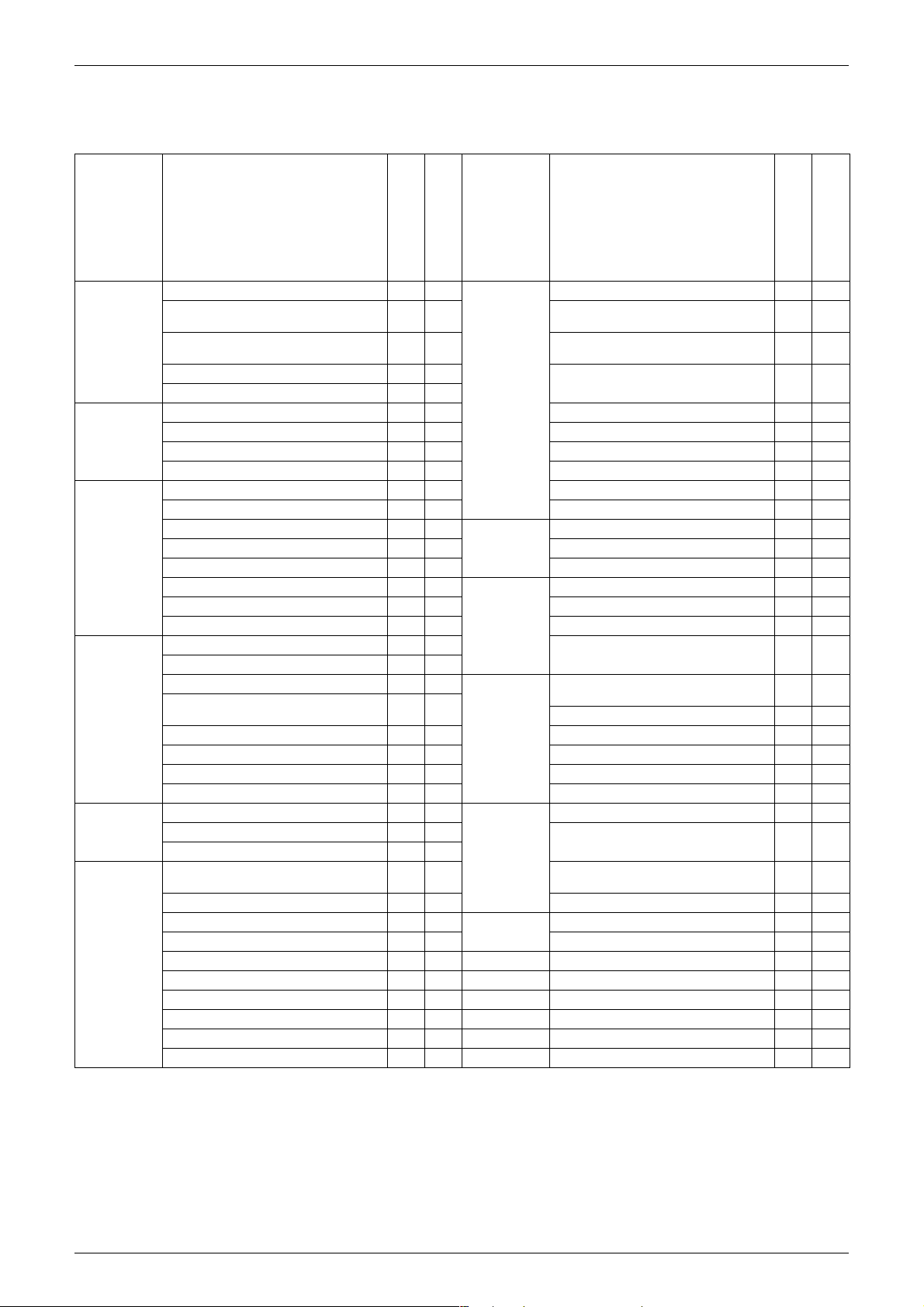
1. Functions
Category Functions
FTKM18/24/28PVMK
RKM18/24/28PVMK
Basic
Function
Compressor Oval scroll compressor — — Air filter (prefilter)
Comfortable
Airflow
Comfort
Control
Operation Automatic operation —
Lifestyle
Convenience
Inverter (with inverter power control)
Operation limit for cooling (°CDB)
Operation limit for heating (°CWB) —
PAM control
Standby electricity saving
Swing compressor
Rotary compressor — — Washable grille — —
Reluctance DC motor
Power-airflow flap — — Heating dry operation — —
Power-airflow dual flaps
Power-airflow diffuser — — Timer WEEKLY TIMER operation
Wide-angle louvers
Auto-swing (up and down)
Auto-swing (right and left)
3-D airflow
COMFORT AIRFLOW operation
Auto fan speed
Indoor unit quiet operation
NIGHT QUIET mode (automatic) — — Flexibility Multi-split / split type compatible indoor
OUTDOOR UNIT QUIET operation
(manual)
INTELLIGENT EYE operation
Quick warming function —
Hot-start function —
Automatic defrosting —
Program dry operation
Fan only
New POWERFUL operation
(non-inverter)
Inverter POWERFUL operation
Priority-room setting — — Remote
COOL / HEAT mode lock — — Wired — —
HOME LEAVE operation — —
ECONO operation
Indoor unit ON/OFF button
Signal receiving sign
R/C with back light
Temperature display — —
Note: z
: Available
zz
10 ~ 5210 ~
zz
zz
zz
zz
zz
zz
zz
zz
zz
zz
zz
zz
zz
zz
zz
zz
——
zz
zz
zz
zz
zz
Category Functions
FTXM18/24/28PVMK
RXM18/24/28PVMK
52
~
0
18
z
z
z
z
Health &
Clean
Worry Free
(Reliability &
Durability)
Remote
Control
Controller
Air-purifying filter — —
Photocatalytic deodorizing filter — —
Air-purifying filter with photocatalytic
deodorizing function
Titanium apatite photocatalytic
air-purifying filter
Wipe-clean flat panel
MOLD PROOF operation — —
Good-sleep cooling operation — —
24-hour ON/OFF timer
NIGHT SET mode
Auto-restart (after power failure)
Self-diagnosis (R/C, LED)
Wiring error check function — —
Anti-corrosion treatment of outdoor
heat exchanger
unit
Flexible power supply correspondence
High ceiling application — —
Chargeless 10 m 10 m
Either side drain (right or left)
Power selection — —
5-room centralized controller (option)
Remote control adaptor
(normal open pulse contact) (option)
Remote control adaptor (normal open
contact) (option)
DIII-NET compatible (adaptor) (option)
Wireless
— : Not available
FTKM18/24/28PVMK
RKM18/24/28PVMK
FTXM18/24/28PVMK
RXM18/24/28PVMK
——
zz
zz
zz
zz
zz
zz
zz
zz
zz
——
zz
zz
zz
zz
zz
zz
zz
List of Functions 2

SiMT041509E
Part 2
Specifications
1. Specifications..........................................................................................4
3 Specifications
SiMT041509E Specifications
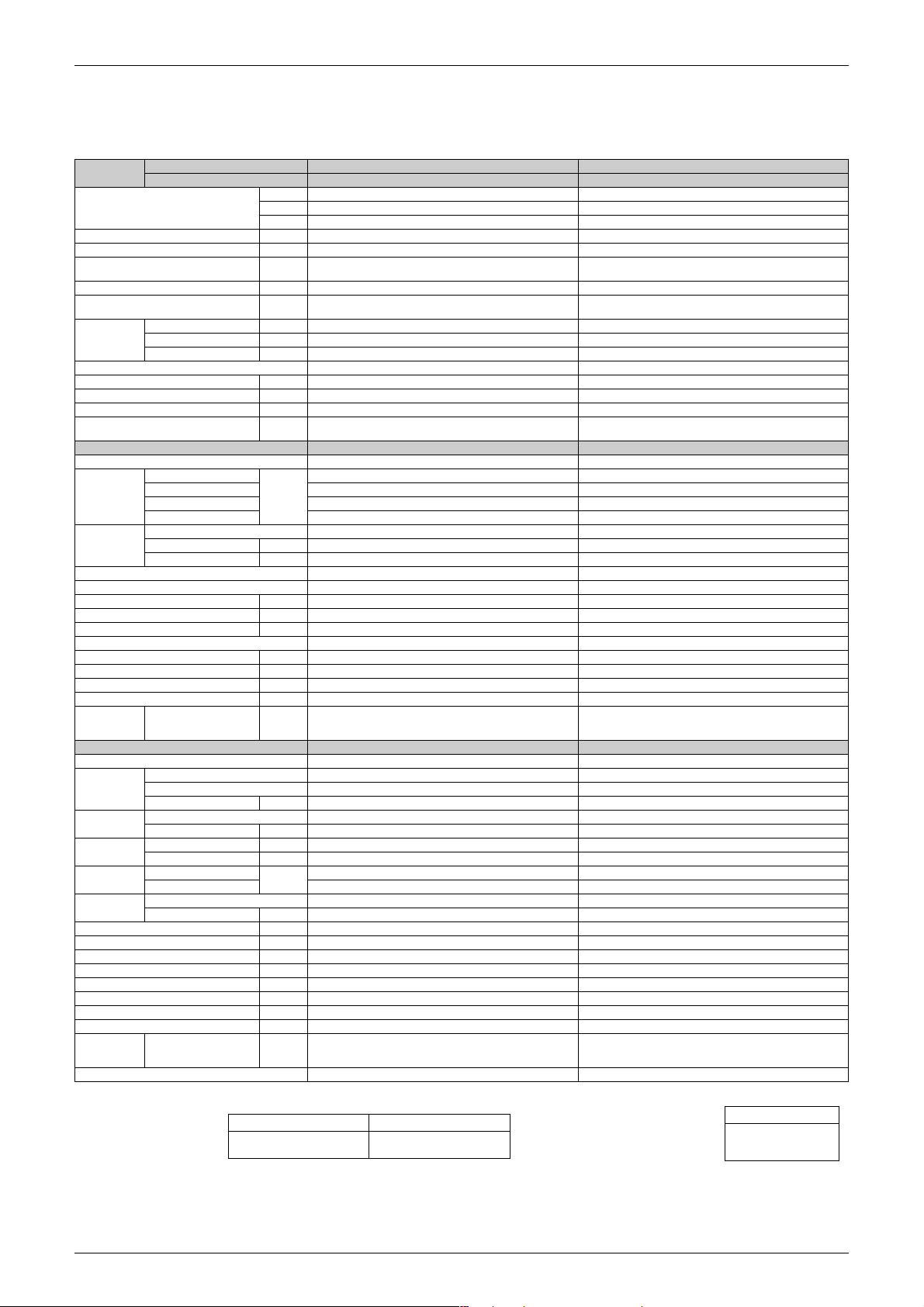
1. Specifications
50 Hz, 220 - 230 - 240 V / 60 Hz, 220 - 230 V
Model
Capacity
Rated (Min. ~ Max.)
Moisture Removal L/h 2.9 4.5
Running Current (Rated) A 6.4 - 6.1 - 5.8 / 6.4 - 6.1 8.8 - 8.4 - 8.1 / 8.8 - 8.4
Power Consumption
Rated (Min. ~ Max.)
Power Factor (Rated) % 95.9 - 96.2 - 97.0 / 95.9 - 96.2 97.6 - 97.8 - 97.2 / 97.6 - 97.8
COP
Rated (Min. ~ Max.)
Piping
Connections
Heat Insulation Both Liquid and Gas Pipes Both Liquid and Gas Pipes
Max. Interunit Piping Length m 30 30
Max. Interunit Height Difference m 20 20
Chargeless m 10 10
Amount of Additional Charge of
Refrigerant
Indoor Unit FTKM18PVMK FTKM24PVMK
Front Panel Color (Mancel No.) White (N95) White (N95)
Airflow Rate
Fan
Air Direction Control Right, Left, Horizontal, Downward Right, Left, Horizontal, Downward
Air Filter Removable, Washable, Mildew Proof Removable, Washable, Mildew Proof
Running Current (Rated) A 0.45 - 0. 43 - 0.41 / 0.45 - 0.43 0.70- 0.67 - 0.64 / 0.70 - 0.67
Power Consumption (Rated) W 59 85
Power Factor (Rated) % 59.6 - 59.7 - 60.0 / 59.6 - 59.7 55.2 - 55.2 - 55.3 / 55.2 - 55.2
Temperature Control Microcomputer Control Microcomputer Control
Dimensions (H × W × D) mm 340 × 1,050 × 259 340 × 1,050 × 259
Packaged Dimensions (H × W × D) mm 342 × 1,160 × 429 342 × 1,160 × 429
Weight (Mass) kg 15 15
Gross Weight (Gross Mass) kg 21 21
Sound
Pressure
Level
Outdoor Unit RKM18PVMK RKM24PVMK
Casing Color Ivory White Ivory White
Compressor
Refrigerant
Oil
Refrigerant
Airflow Rate
Fan
Running Current (Rated) A 6.1 - 5.8 - 5.5 / 6.1 - 5.8 8.4 - 8.0 - 7.7 / 8.4 - 8.0
Power Consumption (Rated) W 1,291 1,805
Power Factor (Rated) % 96.2 - 96.8 - 97.8 / 96.2 - 96.8 97.7 - 98.1 - 97.7 / 97.7 - 98.1
Starting Current A 6.4 8.8
Dimensions (H × W × D) mm 695 × 930 × 350 695 × 930 × 350
Packaged Dimensions (H × W × D) mm 762 × 1,004 × 475 762 × 1,004 × 475
Weight (Mass) kg 46 49
Gross Weight (Gross Mass) kg 52 56
Sound
Pressure
Level
Drawing No. 3D093404 3D093405
Indoor Unit FTKM18PVMK FTKM24PVMK
Outdoor Unit RKM18PVMK RKM24PVMK
Liquid mm φ 6.4 φ 6.4
Gas mm φ 12.7 φ 12.7
Drain mm — —
H
M 16.5 (583) 17.7 (625)
L 12.6 (445) 13.7 (484)
SL 10.9 (385) 12.2 (431)
Type Cross Flow Fan Cross Flow Fan
Motor Output W 48 48
Speed Steps 5 Steps, Quiet, Auto 5 Steps, Quiet, Auto
H / M / L / SL dB(A) 48 / 42 / 35 / 32 51 / 45 / 37 / 34
Type Hermetically Sealed Swing Type Hermetically Sealed Swing Type
Model 2YC40BXD 2YC40BXD
Motor Output W 1,300 1,300
Type FW68DA FW68DA
Charge L 0.650 0.650
Type R-32 R-32
Charge kg 1.12 1.40
H
SL 62.0 (2,189) 61.4 (2,168)
Type Propeller Propeller
Motor Output W 128 128
HdB(A) 51 56
kW 5.28 (1.7 ~ 6.0) 7.03 (1.9 ~ 8.6)
Btu/h 18,000 (5,700 ~ 20,500) 24, 000 (6,500 ~ 29,500)
kcal/h 4,540 (1,440 ~ 5,170) 6,050 (1,640 ~ 7,430)
W 1,350 (300 ~ 1,700) 1,890 (350 ~ 2,600)
W/W 3.91 (5.57 ~ 3.54) 3.72 (5.46 ~ 3.32)
g/m 20 20
20.5 (724) 22.0 (777)
m³/min
(cfm)
m³/min
(cfm)
76.9 (2,715) 74.2 (2,620)
Note:
The data are based on the conditions shown in the table below.
Cooling Piping Length
Indoor ; 27°CDB / 19°CWB
Outdoor ; 35°CDB / 24°CWB
7.5 m
Conversion Formulae
kcal/h = kW × 860
Btu/h = kW × 3412
cfm = m³/min × 35.3
Specifications 4
Specifications SiMT041509E
50 Hz, 220 - 230 - 240 V / 60 Hz, 220 - 230 V
Model
Capacity
Rated (Min. ~ Max.)
Moisture Removal L/h 5.6
Running Current (Rated) A 10.7 - 10.2 - 9.8 / 10.7 - 10.2
Power Consumption
Rated (Min. ~ Max.)
Power Factor (Rated) % 98.1 - 98.5 - 98.2 / 98.1 - 98.5
COP
Rated (Min. ~ Max.)
Piping
Connections
Heat Insulation Both Liquid and Gas Pipes
Max. Interunit Piping Length m 30
Max. Interunit Height Difference m 20
Chargeless m 10
Amount of Additional Charge of
Refrigerant
Indoor Unit FTKM28PVMK
Front Panel Color (Mancel No.) White (N95)
Airflow Rate
Fan
Air Direction Control Right, Left, Horizontal, Downward
Air Filter Removable, Washable, Mildew Proof
Running Current (Rated) A 0.74- 0.71 - 0.68 / 0.74 - 0.71
Power Consumption (Rated) W 91
Power Factor (Rated) % 55.9 - 55.7 - 55.8 / 55.9 - 55.7
Temperature Control Microcomputer Control
Dimensions (H × W × D) mm 340 × 1,200 × 259
Packaged Dimensions (H × W × D) mm 342 × 1,310 × 429
Weight (Mass) kg 18
Gross Weight (Gross Mass) kg 25
Sound
Pressure
Level
Outdoor Unit RKM28PVMK
Casing Color Ivory White
Compressor
Refrigerant
Oil
Refrigerant
Airflow Rate
Fan
Running Current (Rated) A 10.3 - 9.8 - 9.4 / 10.3 - 9.8
Power Consumption (Rated) W 2,219
Power Factor (Rated) % 97.9 - 98.4 - 98.4 / 97.9 - 98.4
Starting Current A 10.7
Dimensions (H × W × D) mm 695 × 930 × 350
Packaged Dimensions (H × W × D) mm 762 × 1,004 × 475
Weight (Mass) kg 49
Gross Weight (Gross Mass) kg 56
Sound
Pressure
Level
Drawing No. 3D093406
Indoor Unit FTKM28PVMK
Outdoor Unit RKM28PVMK
Liquid mm φ 6.4
Gas mm φ 15.9
Drain mm —
H
M 20.6 (727)
L 16.3 (576)
SL 14.5 (512)
Type Cross Flow Fan
Motor Output W 64
Speed Steps 5 Steps, Quiet, Auto
H / M / L / SL dB(A) 54 / 49 / 42 / 39
Type Hermetically Sealed Swing Type
Model 2YC40BXD
Motor Output W 1,300
Type FW68DA
Charge L 0.650
Type R-32
Charge kg 1.60
H
SL 61.4 (2,168)
Type Propeller
Motor Output W 128
HdB(A) 57
kW 8.21 (1.9 ~ 9.4)
Btu/h 28,000 (6,500 ~ 32,000)
kcal/h 7,060 (1,640 ~ 8,070)
W 2,310 (310 ~ 3,030)
W/W 3.55 (6.16 ~ 3.10)
g/m 20
25.2 (890)
m³/min
(cfm)
m³/min
(cfm)
79.0 (2,789)
The data are based on the conditions shown in the table below.
Note:
Cooling Piping Length
Indoor ; 27°CDB / 19°CWB
Outdoor ; 35°CDB / 24°CWB
7.5 m
Conversion Formulae
kcal/h = kW × 860
Btu/h = kW × 3412
cfm = m³/min × 35.3
5 Specifications
SiMT041509E Specifications
50 Hz, 220 - 230 - 240 V / 60 Hz, 220 - 230 V
Model
Capacity
Rated (Min. ~ Max.)
Moisture Removal L/h 2.9 — 4.5 —
Running Current (Rated) A 6.4 - 6.1 - 5.8 / 6.4 - 6.1 5.9 - 5.6 - 5.4 / 5.9 - 5.6 8.8 - 8.4 - 8.1 / 8.8 - 8.4 7.2 - 6.9 - 6.6 / 7.2 - 6.9
Power Consumption
Rated (Min. ~ Max.)
Power Factor (Rated) %
COP
Rated (Min. ~ Max.)
Piping
Connections
Heat Insulation Both Liquid and Gas Pipes Both Liquid and Gas Pipes
Max. Interunit Piping Length m 30 30
Max. Interunit Height Difference m 20 20
Chargeless m 10 10
Amount of Additional Charge of
Refrigerant
Indoor Unit FTXM18PVMK FTXM24PVMK
Front Panel Color (Mancel No.) White (N95) White (N95)
Airflow Rate
Fan
Air Direction Control Right, Left, Horizontal, Downward Right, Left, Horizontal, Downward
Air Filter Removable, Washable, Mildew Proof Removable, Washable, Mildew Proof
Running Current (Rated) A
Power Consumption (Rated) W 59 65 85 85
Power Factor (Rated) %
Temperature Control Microcomputer Control Microcomputer Control
Dimensions (H × W × D) mm 340 × 1,050 × 259 340 × 1,050 × 259
Packaged Dimensions (H × W × D) mm 342 × 1,160 × 429 342 × 1,160 × 429
Weight (Mass) kg 15 15
Gross Weight (Gross Mass) kg 21 21
Sound
Pressure
Level
Outdoor Unit RXM18PVMK RXM24PVMK
Casing Color Ivory White Ivory White
Compressor
Refrigerant
Oil
Refrigerant
Airflow Rate
Fan
Running Current (Rated) A 6.1 - 5.8 - 5.5 / 6.1 - 5.8 5.6 - 5.3 - 5.1 / 5.6 - 5.3 8.4 - 8.0 - 7.7 / 8.4 - 8.0 6.8 - 6.5 - 6.2 / 6.8 - 6.5
Power Consumption (Rated) W 1,291 1,185 1,805 1,455
Power Factor (Rated) %
Starting Current A 6.4 8.8
Dimensions (H × W × D) mm 695 × 930× 350 695 × 930× 350
Packaged Dimensions (H × W × D) mm 762 × 1,004 × 475 762 × 1,004 × 475
Weight (Mass) kg 46 49
Gross Weight (Gross Mass) kg 52 56
Sound
Pressure
Level
Drawing No. 3D093401 3D093402
Indoor Unit FTXM18PVMK FTXM24PVMK
Outdoor Unit
kW 5.28 (1.7 ~ 6.0) 5.42 (1.0 ~ 5.4) 7.03 (1.9 ~ 8.6) 6.33 (1.1 ~ 6.3)
Btu/h 18,000 (5,700 ~ 20,500) 18,500 (3,500 ~18,500) 24,000 (6,500 ~ 29,500) 21,600 (3,700 ~ 21,600)
kcal/h 4,540 (1,440 ~ 5,170) 4,660 (890 ~ 4,660) 6,050 (1,640 ~ 7,430) 5,440 (930 ~ 5,440)
W 1,350 (300 ~ 1,700) 1,250 (240 ~ 1,250) 1,890 (350 ~ 2,600) 1,540 (280 ~ 1,540)
W/W 3.91 (5.57 ~ 3.54) 4.34 (4.29 ~ 4.34) 3.72 (5.46 ~ 3.32) 4.11 (3.86 ~ 4.11)
Liquid mm φ 6.4 φ 6.4
Gas mm φ 12.7 φ 12.7
Drain mm φ 16.0 φ 16.0
g/m 20 20
H
M 16.5 (583) 17.5 (618) 17.7 (625) 17.7 (625)
L 12.6 (445) 13.4 (473) 13.7 (484) 13.8 (487)
SL 10.9 (385) 11.7 (413) 12.2 (431) 12.0 (424)
Type Cross Flow Fan Cross Flow Fan
Motor Output W 48 48
Speed Steps 5 Steps, Quiet, Auto 5 Steps, Quiet, Auto
H / M / L / SL dB(A) 48 / 42 / 35 / 32 50 / 42 / 34 / 31 51 / 45 / 37 / 34 51 / 43 / 35 / 32
Type Hermetically Sealed Swing Type Hermetically Sealed Swing Type
Model 2YC40BXD 2YC40BXD
Motor Output W 1,300 1,300
Type FW68DA FW68DA
Charge L 0.650 0.650
Type R-32 R-32
Charge kg 1.12 1.40
H
SL 62.0 (2,189) 48.3 (1,705) 61.4 (2,168) 55.3 (1,953)
Type Propeller Propeller
Motor Output W 128 128
H dB(A) 51 51 56 55
m³/min
(cfm)
m³/min
(cfm)
Cooling Heating Cooling Heating
95.9 - 96.2 - 97.0 /
95.9 - 96.2
20.5 (724) 22.2 (784) 22.0 (777) 22.9 (809)
0.45 - 0.43 - 0.41 /
0.45 - 0.43
59.6 - 59.7 - 60.0 /
59.6 - 59.7
76.9 (2,715) 49.8 (1,758) 74.2 (2,620) 62.5 (2,207)
96.2 - 96.8 - 97.8 /
96.2 - 96.8
RXM18PVMK RXM24PVMK
96.3 - 97.0 - 96.5 /
96.3 - 97.0
0.49 - 0.47 - 0.45 /
0.49 - 0.47
60.3 - 60.1 - 60.2 /
60.3 - 60.1
96.2 - 97.2 - 96.8 /
96.2 - 97.2
97.6 - 97.8 - 97.2 /
97.6 - 97.8
0.70 - 0.67 - 0.64 /
0.70 - 0.67
55.2 - 55.2 - 55.3 /
55.2 - 55.2
97.7 - 98.1 - 97.7 /
97.7 - 98.1
97.2 - 97.0 - 97.2 /
97.2 - 97.0
0.70 - 0.67 - 0.64 /
0.70 - 0.67
55.2 - 55.2 - 55.3 /
55.2 - 55.2
97.3 - 97.3 - 97.8 /
97.3 - 97.3
Note:
The data are based on the conditions shown in the table below.
Outdoor ; 35°CDB / 24°CWB
Cooling Heating Piping Length
Indoor ; 27°CDB / 19°CWB
Indoor ; 20°CDB
Outdoor ; 7°CDB / 6°CWB
7.5 m
Conversion Formulae
kcal/h = kW × 860
Btu/h = kW × 3412
cfm = m³/min × 35.3
Specifications 6
Specifications SiMT041509E
50 Hz, 220 - 230 - 240 V / 60 Hz, 220 - 230 V
Model
Capacity
Rated (Min. ~ Max.)
Moisture Removal L/h 5.6 —
Running Current (Rated) A 10.7 - 10.2 - 9.8 / 10.7 - 10.2 8.4 - 8.0 - 7.7 / 8.4 - 8.0
Power Consumption
Rated (Min. ~ Max.)
Power Factor (Rated) % 98.1 - 98.5 - 98.2 / 98.1 - 98.5 95.2 - 95.7 - 95.2 / 95.2 - 95.7
COP
Rated (Min. ~ Max.)
Piping
Connections
Heat Insulation Both Liquid and Gas Pipes
Max. Interunit Piping Length m 30
Max. Interunit Height Difference m 20
Chargeless m 10
Amount of Additional Charge of
Refrigerant
Indoor Unit FTXM28PVMK
Front Panel Color (Mancel No.) White (N95)
Airflow Rate
Fan
Air Direction Control Right, Left, Horizontal, Downward
Air Filter Removable, Washable, Mildew Proof
Running Current (Rated) A 0.74 - 0. 71 - 0.68 / 0.74 - 0.71 0.69 - 0.66 - 0.63 / 0.69 - 0.66
Power Consumption (Rated) W 91 84
Power Factor (Rated) % 55.9 - 55.7 - 55.8 / 55.9 - 55.7 55.3 - 55.3 - 55.6 / 55.3 - 55.3
Temperature Control Microcomputer Control
Dimensions (H × W × D) mm 340 × 1,200 × 259
Packaged Dimensions (H × W × D) mm 342 × 1,310 × 429
Weight (Mass) kg 18
Gross Weight (Gross Mass) kg 25
Sound
Pressure
Level
Outdoor Unit RXM28PVMK
Casing Color Ivory White
Compressor
Refrigerant
Oil
Refrigerant
Airflow Rate
Fan
Running Current (Rated) A 10.3 - 9.8 - 9.4 / 10.3 - 9.8 8.0 - 7.6 - 7.3 / 8.0 - 7.6
Power Consumption (Rated) W 2,219 1,676
Power Factor (Rated) % 97.9 - 98.4 - 98.4 / 97.9 - 98.4 95.2 - 95.9 - 95.7 / 95.2 - 95.9
Starting Current A 10.7
Dimensions (H × W × D) mm 695 × 930× 350
Packaged Dimensions (H × W × D) mm 762 × 1,004 × 475
Weight (Mass) kg 49
Gross Weight (Gross Mass) kg 56
Sound
Pressure
Level
Drawing No. 3D093403
Indoor Unit FTXM28PVMK
Outdoor Unit
kW 8.21 (1.9 ~ 9.4) 6.57 (1.1 ~ 6.6)
Btu/h 28,000 (6,500 ~ 32,000) 22, 400 (3,700 ~ 22,400)
kcal/h 7,060 (1,640 ~ 8,070) 5,650 (930 ~ 5,650)
W 2,310 (310 ~ 3,030) 1,760 (270 ~ 1,760)
W/W 3.55 (6.16 ~ 3.10) 3.73 (4.00 ~ 3.73)
Liquid mm φ 6.4
Gas mm φ 15.9
Drain mm φ 16.0
g/m 20
H
M 20.6 (727) 21.2 (749)
L 16.3 (576) 16.2 (572)
SL 14.5 (512) 14.9 (526)
Type Cross Flow Fan
Motor Output W 64
Speed Steps 5 Steps, Quiet, Auto
H / M / L / SL dB(A) 54 / 49 / 42 / 39 53 / 45 / 38 / 35
Type Hermetically Sealed Swing Type
Model 2YC40BXD
Motor Output W 1,300
Type FW68DA
Charge L 0.650
Type R-32
Charge kg 1.60
H
SL 61.4 (2,168) 55.3 (1,953)
Type Propeller
Motor Output W 128
HdB(A) 57 57
m³/min
(cfm)
m³/min
(cfm)
Cooling Heating
25.2 (890) 27.2 (960)
79.0 (2,789) 66.8 (2,359)
RXM28PVMK
The data are based on the conditions shown in the table below.
Note:
Cooling Heating Piping Length
Indoor ; 27°CDB / 19°CWB
Outdoor ; 35°CDB / 24°CWB
Indoor ; 20°CDB
Outdoor ; 7°CDB / 6°CWB
7.5 m
Conversion Formulae
kcal/h = kW × 860
Btu/h = kW × 3412
cfm = m³/min × 35.3
7 Specifications

SiMT041509E
Connector Wiring Diagram
Part 3
Printed Circuit Board
1. Indoor Unit...............................................................................................9
2. Outdoor Unit..........................................................................................11
Printed Circuit Board Connector Wiring Diagram 8
Indoor Unit SiMT041509E
1. Indoor Unit
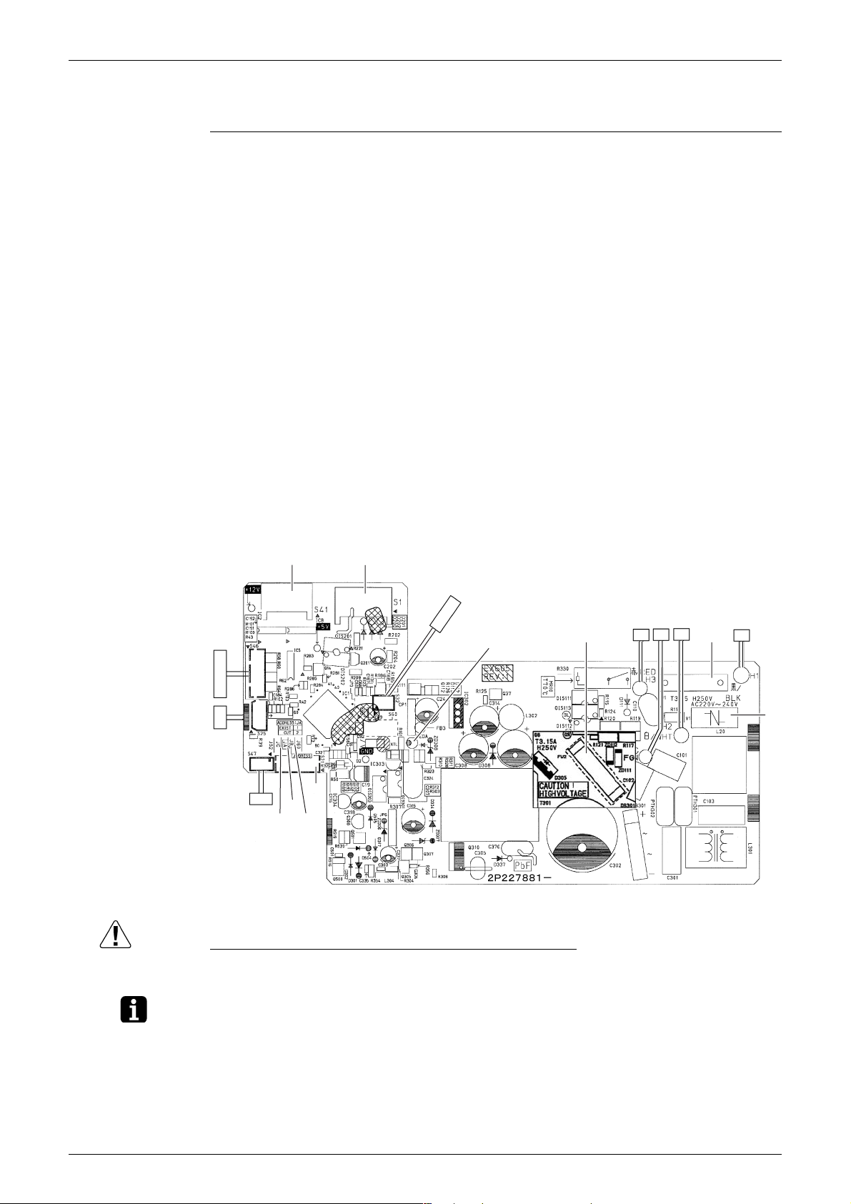
Control PCB
(PCB1)
1) S1 Connector for DC fan motor
2) S21 Connector for centralized control (HA)
3) S25 Connector for INTELLIGENT EYE sensor PCB
4) S32 Indoor heat exchanger thermistor
5) S41 Connector for swing motors
6) S46 Connector for display PCB
7) S47 Connector for signal receiver PCB
8) H1, H2, H3, FG Connector for terminal board
9) JA Address setting jumper
∗ Refer to page 94 for detail.
10)JB Fan speed setting when compressor stops for thermostat OFF
∗ Refer to page 94 for detail.
11)JC Power failure recovery function (auto-restart)
∗ Refer to page 94 for detail.
12)LED A LED for service monitor (green)
13)FU1 (F1U),
Fuse (3.15 A, 250 V)
FU2 (F2U)
14)V1 Varistor
S1S41
S32
LED A
S46
S25
S21
JA
S47
JC
JB
Caution Replace the PCB if you accidentally cut a wrong jumper.
Jumpers are necessary for electronic circuit. Improper operation may occur if you cut any of
them.
FU2
H2FGH3
FU1
2P227881-10
2P227881-11
H1
V1
Note: The symbols in the parenthesis are the names on the appropriate wiring diagram.
9 Printed Circuit Board Connector Wiring Diagram
SiMT041509E Indoor Unit
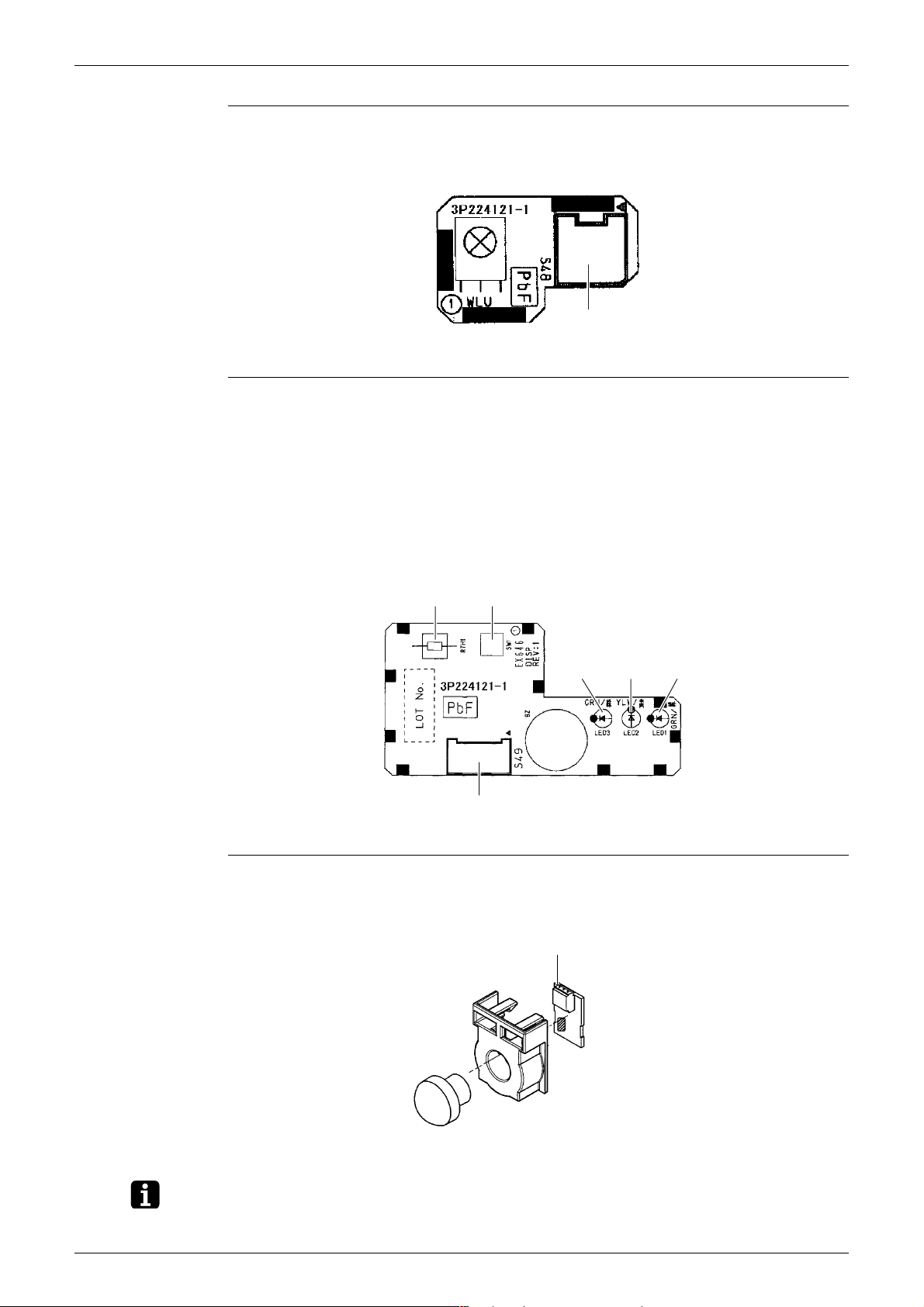
Signal Receiver
PCB (PCB2)
1) S48 Connector for control PCB
S48
3P224121-1
Display PCB
(PCB3)
1) S49 Connector for control PCB
2) SW1 Forced cooling operation ON/OFF button
∗ Refer to page 92 for detail.
3) LED1 (H1P) LED for operation (green)
4) LED2 (H2P) LED for timer (yellow)
5) LED3 (H3P) LED for INTELLIGENT EYE (green)
6) RTH1 (R1T) Room temperature thermistor
INTELLIGENT
EYE Sensor PCB
(PCB4)
RTH1 SW1
S49
1) S36 Connector for control PCB
S36
LED3
LED2
3P224121-1
LED1
3P227885-1
Note: The symbols in the parenthesis are the names on the appropriate wiring diagram.
Printed Circuit Board Connector Wiring Diagram 10
Outdoor Unit SiMT041509E
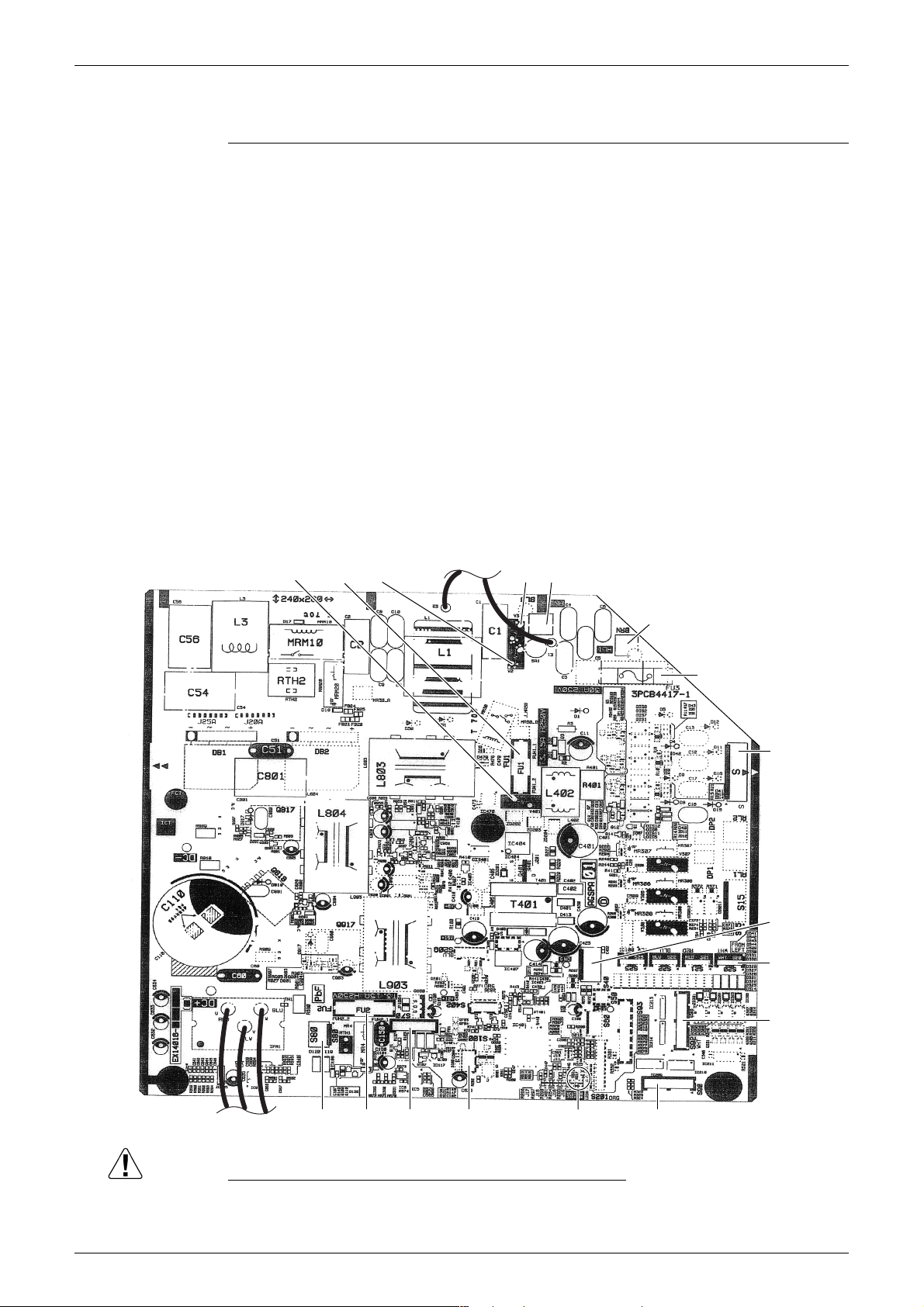
2. Outdoor Unit
Main PCB
1) S20 Connector for electronic expansion valve coil
2) S40 Connector for overload protector and high pressure switch
3) S70 Connector for DC fan motor
4) S80 Connector for four way valve coil
5) S90 Connector for thermistors
(outdoor temperature, outdoor heat exchanger, discharge pipe)
6) S92 Jumpers for local setting
∗ Neither disconnect the connector nor cut any of the jumpers.
7) S100 Connector for fan motor (for cooling electrical box)
8) HL1, HN1, S Connector for terminal board
9) E1, E2 Terminal for earth wire
10) U, V, W Connector for compressor
11) FU1, FU2 Fuse (3.15 A, 250 V)
12) FU3 Fuse (30 A, 250 V)
13) LED A LED for service monitor (green)
14) V2, V3, V401 Varistor
V401
FU1
V2
E2 E1
V3
HN1
HL1
FU3
S
S40
S20
S92
UV W
FU2S80
S70
S100
LED A
S90
2P387226-1
Caution Replace the PCB if you accidentally cut a wrong jumper.
Jumpers are necessary for electronic circuit. Improper operation may occur if you cut any of
them.
11 Printed Circuit Board Connector Wiring Diagram

SiMT041509E
Part 4
Function and Control
1. Main Functions......................................................................................13
1.1 Temperature Control ..............................................................................13
1.2 Frequency Principle................................................................................13
1.3 Airflow Direction Control.........................................................................15
1.4 Fan Speed Control for Indoor Unit .........................................................16
1.5 Program Dry Operation ..........................................................................17
1.6 Automatic Operation...............................................................................18
1.7 Thermostat Control.................................................................................19
1.8 NIGHT SET Mode ..................................................................................20
1.9 ECONO Operation .................................................................................20
1.10 INTELLIGENT EYE Operation ...............................................................21
1.11 Inverter POWERFUL Operation .............................................................22
1.12 Clock Setting ..........................................................................................23
1.13 WEEKLY TIMER Operation ...................................................................24
1.14 Other Functions......................................................................................30
2. Function of Thermistor ..........................................................................31
3. Control Specification .............................................................................32
3.1 Mode Hierarchy ......................................................................................32
3.2 Frequency Control ..................................................................................33
3.3 Controls at Mode Changing / Start-up....................................................35
3.4 Discharge Pipe Temperature Control.....................................................36
3.5 Input Current Control ..............................................................................37
3.6 Freeze-up Protection Control .................................................................38
3.7 Heating Peak-cut Control .......................................................................38
3.8 Outdoor Fan Control...............................................................................39
3.9 Liquid Compression Protection Function................................................39
3.10 Defrost Control .......................................................................................40
3.11 Electronic Expansion Valve Control .......................................................41
3.12 Discharge Pipe Thermistor Disconnection Control.................................43
3.13 Malfunctions ...........................................................................................43
Function and Control 12
Main Functions SiMT041509E
1. Main Functions
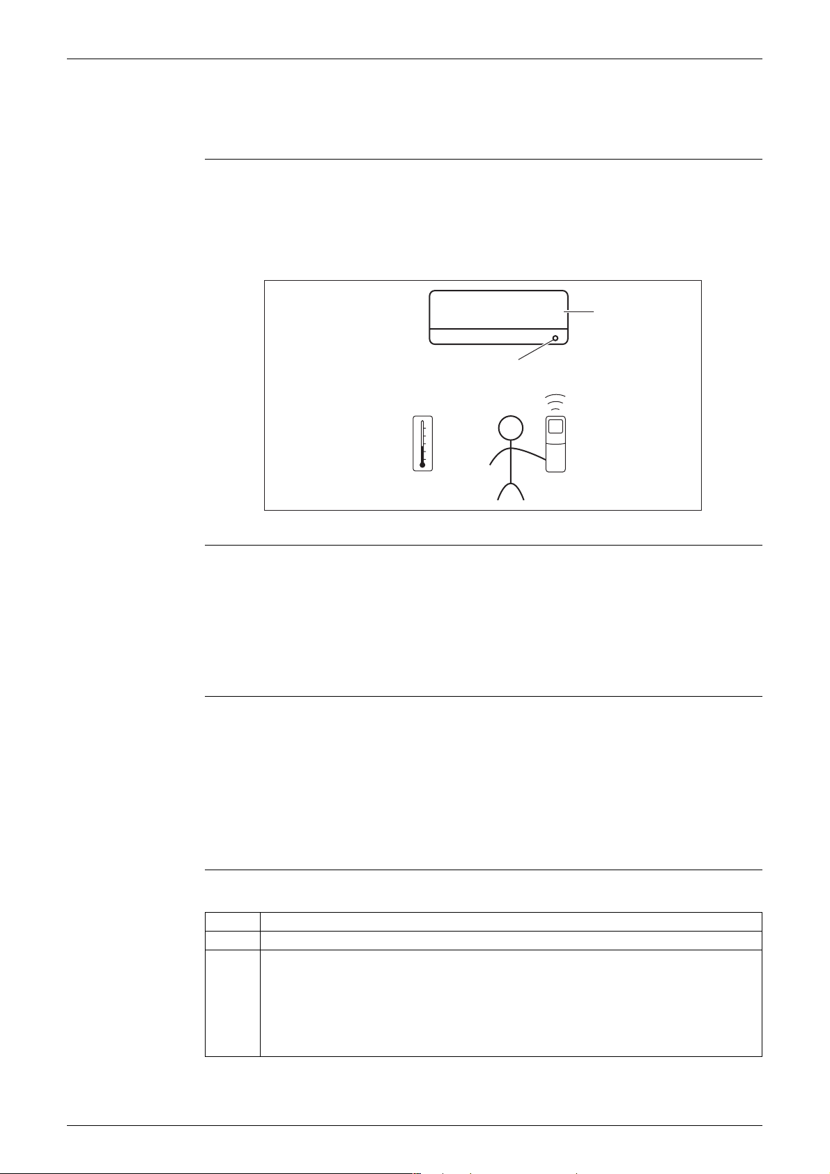
1.1 Temperature Control
Definitions of
Temperatures
Temperature
Control
The definitions of temperatures are classified as following.
Room temperature: temperature of lower part of the room
Set temperature: temperature set by remote controller
Room thermistor temperature: temperature detected by room temperature thermistor
Target temperature: temperature determined by microcomputer
Target temperature
Room thermistor temperature
Set temperature
Room temperature
(R12321)
The temperature of the room is detected by the room temperature thermistor. However, there is
a difference between the temperature detected by room temperature thermistor and the
temperature of lower part of the room, depending on the type of the indoor unit or installation
condition. Practically, the temperature control is done by the target temperature appropriately
adjusted for the indoor unit and the temperature detected by room temperature thermistor.
1.2 Frequency Principle
Control
Parameters
Inverter Principle To regulate the capacity, a frequency control is needed. The inverter makes it possible to
The frequency of the compressor is controlled by the following 2 parameters:
The load condition of the operating indoor unit
The difference between the room thermistor temperature and the target temperature
The target frequency is adapted by additional parameters in the following cases:
Frequency restrictions
Initial settings
Forced cooling operation
control the rotation speed of the compressor. The following table explains the inverter principle:
Phase Description
1 The supplied AC power source is converted into the DC power source for the present.
2 The DC power source is reconverted into the three phase AC power source with variable
frequency.
When the frequency increases, the rotation speed of the compressor increases resulting
in an increase of refrigerant circulation. This leads to a larger amount of heat exchange
per unit.
When the frequency decreases, the rotation speed of the compressor decreases
resulting in a decrease of refrigerant circulation. This leads to a smaller amount of heat
exchange per unit.
13 Function and Control
SiMT041509E Main Functions
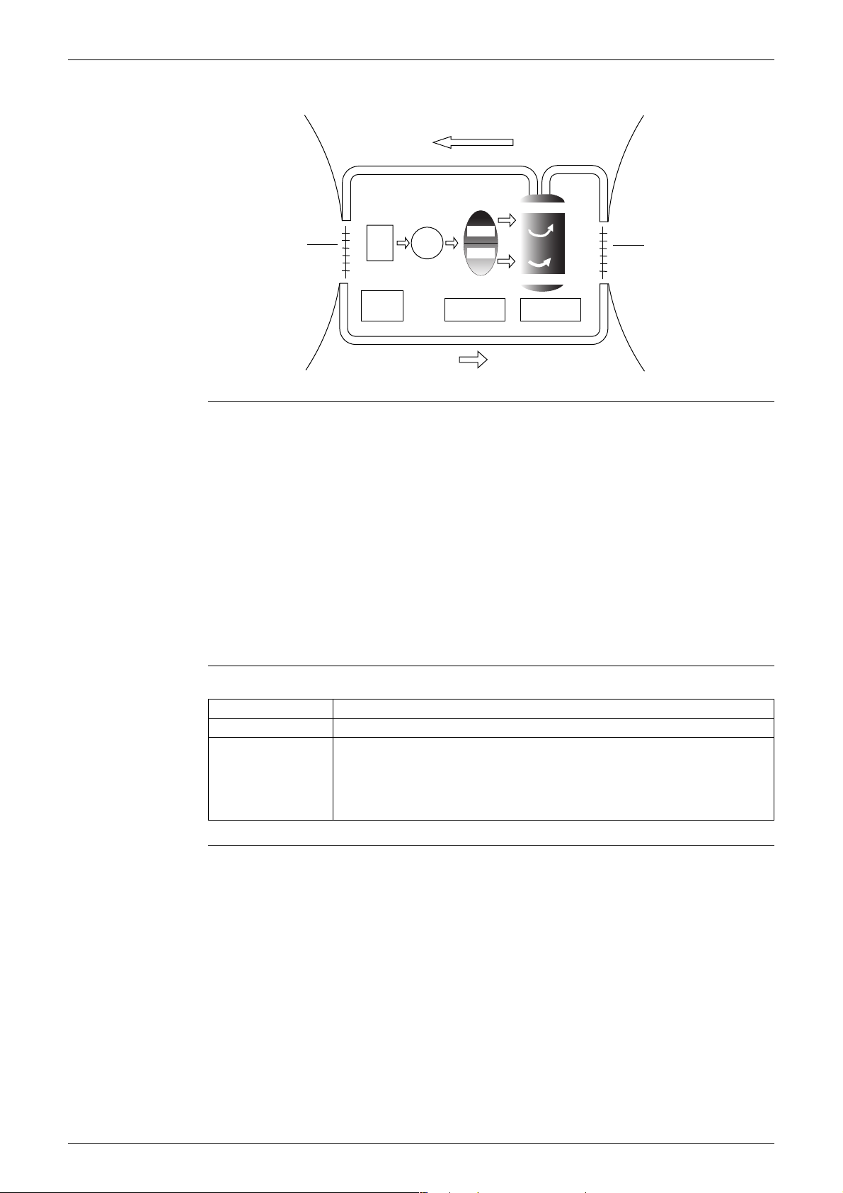
The following drawing shows a schematic view of the inverter principle:
Refrigerant circulation rate (high)
Amount of heat
exchanged air (large)
Amount of heat
exchanged air (small)
AC
freq=
constant
DC
power
power
50 Hz
freq=variable
60 Hz
Refrigerant circulation rate (low)
Inverter Features The inverter provides the following features:
The regulating capacity can be changed according to the changes in the outdoor
temperature and cooling / heating load.
Quick heating and quick cooling
The rotation speed of the compressor is increased when starting the heating (or cooling).
This enables to reach the set temperature quickly.
Even during extreme cold weather, high capacity is achieved. It is maintained even when the
outdoor temperature is 2°C.
Comfortable air conditioning
A fine adjustment is integrated to keep the room temperature constant.
Energy saving heating and cooling
Once the set temperature is reached, the energy saving operation enables to maintain the
room temperature at low power.
high f
low f
high speed
low speed
capacity=
variable
Amount of heat
exchanged air (large)
Amount of heat
exchanged air (small)
(R2812)
Frequency Limits The following functions regulate the minimum and maximum frequency:
Frequency Functions
Low Four way valve operation compensation. Refer to page 35.
High Compressor protection function. Refer to page 36.
Discharge pipe temperature control. Refer to page 36.
Input current control. Refer to page 37.
Freeze-up protection control. Refer to page 38.
Heating peak-cut control. Refer to page 38.
Defrost control. Refer to page 40.
Forced Cooling
Refer to page 92 for detail.
Operation
Function and Control 14
Main Functions SiMT041509E
1.3 Airflow Direction Control
Power-Airflow
Dual Flaps
The large flap sends a large volume of air downward to the floor and provides an optimum
control in cooling, dry, and heating operation.
<Cooling / Dry>
During cooling or dry operation, the flap retracts into the indoor unit. Then, cool air can be blown
far and distributed all over the room.
<Heating>
During heating operation, the large flap directs airflow downward to spread the warm air to the
entire room.
Wide-Angle
Louvers
The louvers, made of elastic synthetic resin, provide a wide range of airflow that guarantees
comfortable air distribution.
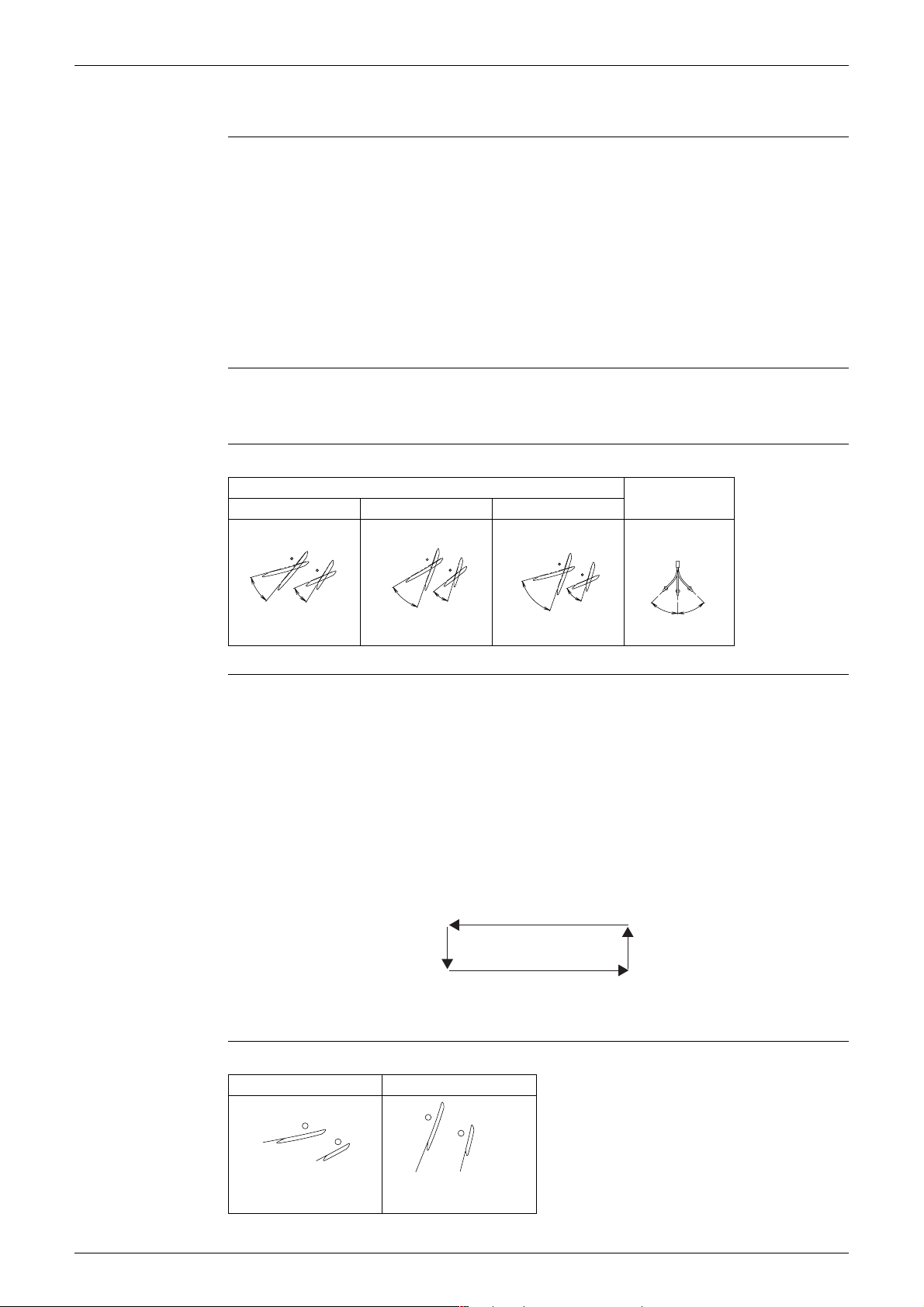
Auto-Swing The following table explains the auto-swing process for cooling, dry, heating, and fan:
Flap (up and down)
Cooling / Dry Heating Fan
°
15
50
°
°
25
°
°
60
(R9303)
30
70
40
°
°
75
°
(R9304)
15
°
°
25
°
75
°
70
(R9305)
Louver
(right and left)
°
45
°
45
(R9306)
3-D Airflow Alternative repetition of vertical and horizontal swing motions enables uniform air-conditioning of
the entire room.
When the horizontal swing and vertical swing are both set to automatic operation, the airflow
becomes 3-D airflow. The horizontal and vertical swing motions are alternated and the airflow
direction changes in the order shown in the following diagram.
(1) The louvers move from the right to the left.
(2) The flaps move downward.
(3) The louvers move from the left to the right.
(4) The flaps move upward.
(1)
COMFORT
AIRFLOW
(2)
(3)
The flaps are controlled not to blow the air directly at the people in the room.
Cooling Heating
(4)
(R13554)
Operation
°
10
20
°
(R22374)
75
°
°
80
(R9654)
15 Function and Control
 Loading...