

Daikin FTK25JV1NB, FTK35JV1NB, RK35JV1NB, FTX25JV1NB, FTX35JV1NB User Manual
...
SIE-86
Table of Contents i
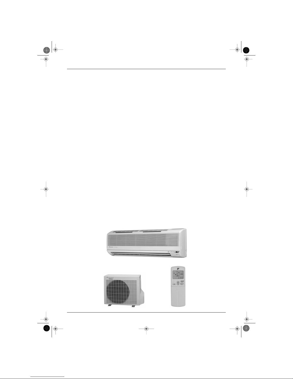
Inverter Pair
FTK(X)-J / RK(X)-J Series
Cooling Only
Indoor Unit
FTK25JV1NB
FTK35JV1NB
Outdoor Unit
RK25JV1NB
RK35JV1NB
Heat Pump
Indoor Unit
FTX25JV1NB
FTX35JV1NB
Outdoor Unit
RX25JV1NB
RX35JV1NB
Si-86.book Page i Friday, June 23, 2000 10:26 AM

SIE-86
ii Table of Contents
1. Introduction .............................................................................................v
1.1 Safety Cautions ....................................................................................... v
Part 1 List of Function .................................................................1
1. Functions.................................................................................................2
1.1 Indoor Unit and Outdoor Unit................................................................... 2
Part 2 Printed Circuit Board Connector Wiring Diagram .............3
1. Printed Circuit Board Connector Wiring Diagram and Name..................4
1.1 FTK25/35J Series, FTX25/35J Series..................................................... 4
1.2 RK25/35J Series, RX25/35J Series......................................................... 6
Part 3 Main Function.....................................................................9
1. General Functionality ............................................................................10
1.1 Functions of Thermistors....................................................................... 10
1.2 Operating Modes................................................................................... 12
1.3 Frequency Principle............................................................................... 13
1.4 Defrost Control ...................................................................................... 15
1.5 Forced Operation Mode......................................................................... 16
1.6 Wide-angle Flaps, Diffuser, Louvres and Autoswing............................. 17
1.7 Fan Speed Control for Indoor Units....................................................... 19
1.8 Fan Speed Control for Outdoor Units.................................................... 20
1.9 General Functions ................................................................................. 21
1.10 Intelligent Eye (J type)........................................................................... 23
1.11 Good Sleep Cooling Control (J Type).................................................... 25
1.12 Automatic Operation.............................................................................. 26
1.13 Input Current Control (H / J Type) ......................................................... 27
1.14 Freeze Protection Function in Cooling. (H / J Type).............................. 28
1.15 Peak-Cut Control Function (H / J Type) ................................................ 29
1.16 Four-Way Valve Function Compensation (H / J Type).......................... 30
1.17 Compressor Protection Function (H / J Type) ....................................... 31
1.18 Wet Operation Protection (H / J Type) .................................................. 32
1.19 Dew Condensation Sweating Prevention Function (H / J type)............. 33
Part 4 System Configuration.......................................................35
1. Instruction..............................................................................................36
1.1 FTK25 / 35J, FTX25 / 35J ..................................................................... 36
Part 5 Service Diagnosis.............................................................51
1. Caution for Diagnosis............................................................................52
1.1 Troubleshooting with The Operation Lamp ........................................... 52
2. Problem Symptoms and Measures.......................................................54
3. Service Check Function ........................................................................55
3.1 ARC423 Series...................................................................................... 55
4. Code Indication on The Remote Controller...........................................56
4.1 Error Codes and Description of Fault .................................................... 56
5. Troubleshooting ....................................................................................57
5.1 Indoor Units ........................................................................................... 57
Si-86.book Page ii Friday, June 23, 2000 10:26 AM
SIE-86
Table of Contents iii
5.2 Outdoor Units ........................................................................................ 58
5.3 Faulty PCB ............................................................................................ 59
5.4 Operation Shutdown Due to High-Pressure Control
or Freeze-Up Protection (Thermistor Activation).................................. 60
5.5 Operation Halt Due to Fan Motor (AC Motor) or Related Abnormality. . 61
5.6 Operation Halt Due to Detection of Thermistor or Related Abnormality 62
5.7 Faulty Indoor Unit PCB.......................................................................... 63
5.8 Faulty Indoor Unit PCB.......................................................................... 64
5.9 Power Supply Abnormalities or Faulty Indoor Printed Circuit Boards ... 65
5.10 Signal Transmission Error (Between Indoor and Outdoor Units) .......... 66
5.11 Operation Halt Due to Detection of CT Error......................................... 67
5.12 Operation Halt Due to Thermistor Error or Disconnection Detection..... 68
5.13 Operation Halt Due to Compressor Startup Error.................................. 69
5.14 Output Overcurrent................................................................................ 70
5.15 Faulty Outdoor Unit PCB....................................................................... 72
5.16 Faulty Outdoor Unit PCB and Transmitting/Receiving Circuit ............... 73
5.17 Operation Halt Due to Detection of Input Over Current......................... 74
6. Check....................................................................................................76
6.1 How to Check ........................................................................................ 76
Part 6 Removal Procedure ..........................................................85
1. For FTK25J, FTK35J, FTX25J, FTX35J ...............................................86
1.1 Removal of Air Filter.............................................................................. 86
1.2 Removal of Front Grille.......................................................................... 88
1.3 Removal of Horizontal Blade and Vertical Blade................................... 90
1.4 Removal of Switch Box, PC Board and Swing Motor............................ 92
1.5 Removal of Heat Exchanger.................................................................. 97
1.6 Install of Drain Plug ............................................................................... 99
1.7 Removal of Fan Rotor and Motor ........................................................ 100
2. For RK25J, RK35J, RX25J, RX35J.....................................................103
2.1 Removal of External Casing................................................................ 103
2.2 Removal of Bellmouth and Left Side Plate.......................................... 105
2.3 Removal of PC Board and Switch Box................................................ 106
2.4 Removal of Propeller Fan and Fan Motor ........................................... 111
2.5 Removal of Compressor Noise Absorption Pad.................................. 112
2.6 Removal of Partition Plate and Reactor. ............................................. 114
2.7 Removal of Four-way Valve. ............................................................... 116
2.8 Removal of Compressor...................................................................... 118
Part 7 Others .............................................................................119
1. Others .................................................................................................120
1.1 Explanation.......................................................................................... 120
Part 8 Appendix.........................................................................123
1. Piping Diagram....................................................................................124
1.1 Indoor Unit........................................................................................... 124
1.2 Outdoor Unit ........................................................................................ 125
2. Wiring Diagram ...................................................................................127
2.1 Indoor Unit........................................................................................... 127
2.2 Outdoor Unit ........................................................................................ 129
Si-86.book Page iii Friday, June 23, 2000 10:26 AM

SIE-86
iv Table of Contents
Index .............................................................................................i
Drawings & Flow Charts ...............................................................iii
Si-86.book Page iv Friday, June 23, 2000 10:26 AM
SIE-86 Introduction
v
1. Introduction
1.1 Safety Cautions
Cautions and
Warnings
Be sure to read the following safety cautions before conducting repair work.
The caution items are classified into “ Warning ” and “ Caution ”. The “ Warning ” items are
especially important since they can lead to death or serious injury if they are not followed closely. The
“
Caution ” items can also lead to serious accidents under some conditions if they are not followed.
Therefore, be sure to observe all the safety caution items described below.
About the pictograms
This symbol indicates an item for which caution must be exercised.
The pictogram shows the item to which attention must be paid.
This symbol indicates a prohibited action.
The prohibited item or action is shown inside or near the symbol.
This symbol indicates an action that must be taken, or an instruction.
The instruction is shown inside or near the symbol.
After the repair work is complete, be sure to conduct a test operation to ensure that the equipment
operates normally, and explain the cautions for operating the product to the customer
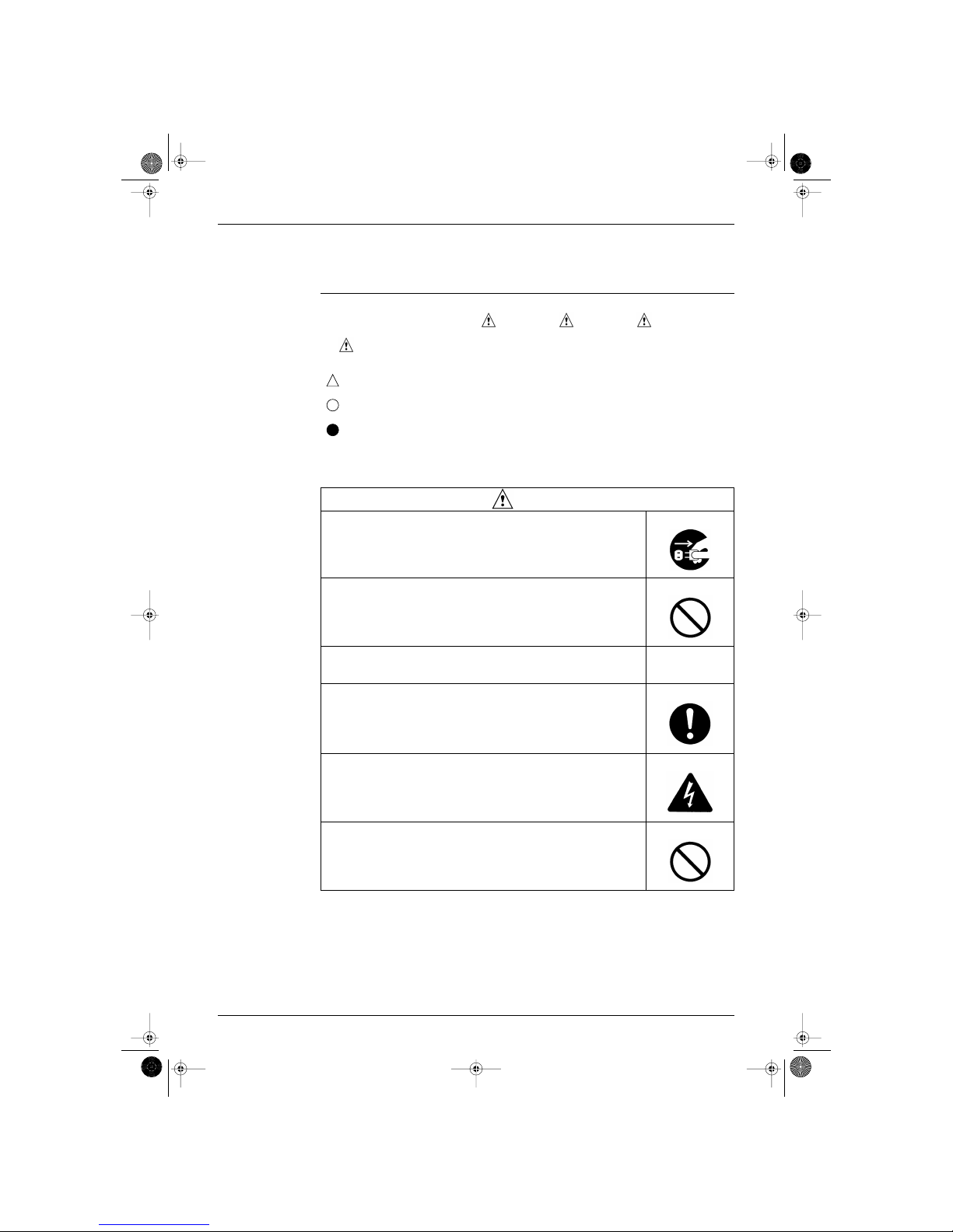
1.1.1 Caution in Repair.
Warning
Be sure to disconnect the power cable plug from the plug socket before disassembling
the equipment for a repair.
Working on the equipment that is connected to a power supply can cause an electrical
shook.
If it is necessary to supply power to the equipment to conduct the repair or inspecting the
circuits, do not touch any electrically charged sections of the equipment.
If the refrigerant gas discharges during the repair work, do not touch the discharging
refrigerant gas.
The refrigerant gas can cause frostbite.
When disconnecting the suction or discharge pipe of the compressor at the welded
section, release the refrigerant gas completely at a well-ventilated place first.
If there is a gas remaining inside the compressor, the refrigerant gas or refrigerating
machine oil discharges when the pipe is disconnected, and it can cause injury.
If the refrigerant gas leaks during the repair work, ventilate the area. The refrigerant gas
can generate toxic gases when it contacts flames.
The step-up capacitor supplies high-voltage electricity to the electrical components of the
outdoor unit.
Be sure to discharge the capacitor completely before conducting repair work.
A charged capacitor can cause an electrical shock.
Do not start or stop the air conditioner operation by plugging or unplugging the power
cable plug.
Plugging or unplugging the power cable plug to operate the equipment can cause an
electrical shock or fire.
Si-86.book Page v Friday, June 23, 2000 10:26 AM
Introduction SIE-86
vi
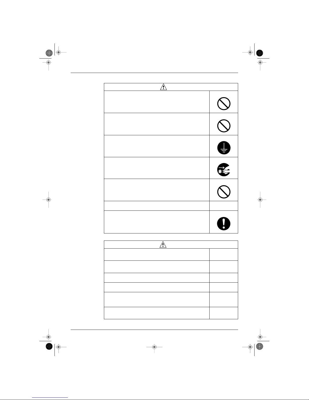
1.1.2 Cautions Regarding Products after Repair
Caution
Do not repair the electrical components with wet hands.
Working on the equipment with wet hands can cause an electrical shock.
Do not clean the air conditioner by splashing water.
Washing the unit with water can cause an electrical shock.
Be sure to provide the grounding when repairing the equipment in a humid or wet place,
to avoid electrical shocks.
Be sure to turn off the power switch and unplug the power cable when cleaning the
equipment.
The internal fan rotates at a high speed, and cause injury.
Do not tilt the unit when removing it.
The water inside the unit can spill and wet the furniture and floor.
Be sure to check that the refrigerating cycle section has cooled down sufficiently before
conducting repair work.
Working on the unit when the refrigerating cycle section is hot can cause burns.
Use the welder in a well-ventilated place.
Using the welder in an enclosed room can cause oxygen deficiency.
Warning
Be sure to use parts listed in the service parts list of the applicable model and appropriate
tools to conduct repair work. Never attempt to modify the equipment.
The use of inappropriate parts or tools can cause an electrical shock, excessive heat
generation or fire.
When relocating the equipment, make sure that the new installation site has sufficient
strength to withstand the weight of the equipment.
If the installation site does not have sufficient strength and if the installation work is not
conducted securely, the equipment can fall and cause injury.
Be sure to install the product correctly by using the provided standard installation frame.
Incorrect use of the installation frame and improper installation can cause the equipment
to fall, resulting in injury.
For integral units only
Be sure to install the product securely in the installation frame mounted on a window
frame.
If the unit is not securely mounted, it can fall and cause injury.
For integral units only
Be sure to use an exclusive power circuit for the equipment, and follow the technical
standards related to the electrical equipment, the internal wiring regulations and the
instruction manual for installation when conducting electrical work.
Insufficient power circuit capacity and improper electrical work can cause an electrical
shock or fire.
Be sure to use the specified cable to connect between the indoor and outdoor units.
Make the connections securely and route the cable properly so that there is no force
pulling the cable at the connection terminals.
Improper connections can cause excessive heat generation or fire.
Si-86.book Page vi Friday, June 23, 2000 10:26 AM
SIE-86 Introduction
vii
1.1.3 Inspection after Repair
When connecting the cable between the indoor and outdoor units, make sure that the
terminal cover does not lift off or dismount because of the cable.
If the cover is not mounted properly, the terminal connection section can cause an
electrical shock, excessive heat generation or fire.
Do not damage or modify the power cable.
Damaged or modified power cable can cause an electrical shock or fire.
Placing heavy items on the power cable, and heating or pulling the power cable can
damage the cable.
Do not mix air or gas other than the specified refrigerant (R22) in the refrigerant system.
If air enters the refrigerating system, an excessively high pressure results, causing
equipment damage and injury.
If the refrigerant gas leaks, be sure to locate the leak and repair it before charging the
refrigerant. After charging refrigerant, make sure that there is no refrigerant leak.
If the leak cannot be located and the repair work must be stopped, be sure to perform
pump-down and close the service valve, to prevent the refrigerant gas from leaking into
the room. The refrigerant gas itself is harmless, but it can generate toxic gases when it
contacts flames, such as fan and other heaters, stoves and ranges.
When replacing the coin battery in the remote controller, be sure to disposed of the old
battery to prevent children from swallowing it.
If a child swallows the coin battery, see a doctor immediately.
Warning
Caution
Installation of a leakage breaker is necessary in some cases depending on the
conditions of the installation site, to prevent electrical shocks.
Do not install the equipment in a place where there is a possibility of combustible gas
leaks.
If a combustible gas leaks and remains around the unit, it can cause a fire.
Be sure to install the packing and seal on the installation frame properly.
If the packing and seal are not installed properly, water can enter the room and wet the
furniture and floor.
For integral units only
Warning
Check to make sure that the power cable plug is not dirty or loose, then insert the plug
into a power outlet all the way.
If the plug has dust or loose connection, it can cause an electrical shock or fire.
If the power cable and lead wires have scratches or deteriorated, be sure to replace
them.
Damaged cable and wires can cause an electrical shock, excessive heat generation or
fire.
Do not use a joined power cable or extension cable, or share the same power outlet with
other electrical appliances, since it can cause an electrical shock, excessive heat
generation or fire.
Caution
Check to see if the parts and wires are mounted and connected properly, and if the
connections at the soldered or crimped terminals are secure.
Improper installation and connections can cause excessive heat generation, fire or an
electrical shock.
Si-86.book Page vii Friday, June 23, 2000 10:26 AM
Introduction SIE-86
viii
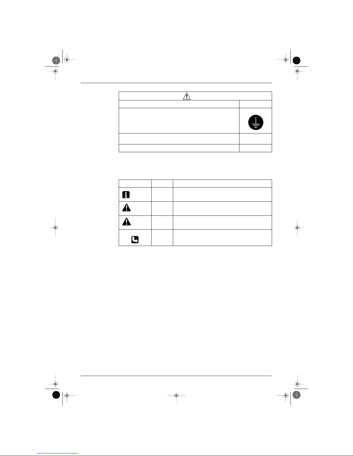
1.1.4 Using Icons
Icons are used to attract the attention of the reader to specific information. The meaning of each icon is
described in the table below:
1.1.5 Using Icons List
If the installation platform or frame has corroded, replace it.
Corroded installation platform or frame can cause the unit to fall, resulting in injury.
Check the grounding, and repair it if the equipment is not properly grounded.
Improper grounding can cause an electrical shock.
Be sure to measure the insulation resistance after the repair, and make sure that the
resistance is 1 Mohm or higher.
Faulty insulation can cause an electrical shock.
Be sure to check the drainage of the indoor unit after the repair.
Faulty drainage can cause the water to enter the room and wet the furniture and floor.
Caution
Icon Type of
Information
Description
Note:
Note A “note” provides information that is not indispensable, but may
nevertheless be valuable to the reader, such as tips and tricks.
Caution
Caution A “caution” is used when there is danger that the reader, through
incorrect manipulation, may damage equipment, loose data, get an
unexpected result or has to restart (part of) a procedure.
Warning
Warning A “warning” is used when there is danger of personal injury.
Reference A “reference” guides the reader to other places in this binder or in this
manual, where he/she will find additional information on a specific topic.
Si-86.book Page viii Friday, June 23, 2000 10:26 AM

SIE-86
List of Function 1
Part 1
List of Function
1. Functions.................................................................................................2
1.1 Indoor Unit and Outdoor Unit................................................................... 2
Si-86.book Page 1 Friday, June 23, 2000 10:26 AM
Functions SIE-86
2 List of Function
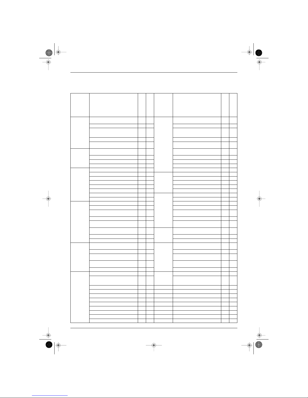
1. Functions
1.1 Indoor Unit and Outdoor Unit
Category Functions
FTK25·35J Series
RK25·35J Series
FTX25·35J Series
RX25·35J Series
Category Functions
FTK25·35J Series
RK25·35J Series
FTX25·35J Series
RX25·35J Series
Basic Funtion
Energy Saving
Health
Health &
Clean
Air Purifying Filter with Bacteriostatic,
Virustatic & Deodrizing Functions
Inverter (with Inverter Power Control)
Longlife Filter — —
Lower Limit of Outdoor Temperature for
Cooling Operation Limit : Outdoor
Temp. ˚C
10˚C 10˚C Ultra-Longlife Filter (Option) — —
Microprocessor Control
Photocatalytic Deodrizing Filter — —
PAM Control (Pulse Amplitude
Modulation Control)
— — Photocatalytic Filter with UV Lamp — —
Compressor
Horizontal Scroll, Oval Scroll
Compressor (DAIKIN SCROLL)
— — Mold Proof Air Filter
Swing Compressor (DAIKIN ROTARY) — — Washable Grille
Rotary Compressor
Filter Cleaning Indicator — —
Reluctance DC Motor — — Healthy Cooling Operation — —
Comfortable
Airflow
Dual Flaps
Good-Sleep Cooling Operation
Power-Airflow Dual Flaps
Timer
72-Hour On/Off Timer — —
Power-Airflow Flap 5 Step Control
24-Hour On/Off Timer
Power-Airflow Diffuser — — 12-Hour Timer — —
Wide-Angle Louvers
Night Set Mode
Vertical Auto-Swing (Up and Down)
Just Fit Thermostatic Timer — —
Horizontal Auto-Swing (Right and Left) — —
Worry Free
“Reliability &
Durability”
Auto-Restart (after Power Failure)
3-Step Airflow (H/P Only) — — Self-Diagnosis Digital Display
“Comfortable
Control”
Comfort
Control
Auto Fan Speed
Self-Diagnosis LED Display — —
Silent-Operation Control — — LCD Remote Controller (Option) — —
Double Thermostat Function — —
The Remote Controller Loss Prevention
with the Chain (Option)
Intelligent Eye
Wiring Error Check — —
Automatic Sensible Comfort Control
Anticorrosion Treatment of Outdoor
Hear Exchanger
Quick Warming Function —
Flexibility
Multi-Split / Split Type Compatible
Indoor Unit
Hot-Start Function —
Flexible Voltage Correspondence
Automatic Defrosting —
Chargeless —
Operation
Automatic Operation —
Remote
Control
5-Rooms Centralized Controller
(Option)
Programme Dry Function
Field-Supply Timer Operation
Height-Ceiling Application — —
Remote Control Adaptor (Option)
(Normal Open-Pluse Contact)
Circulation — —
Remote Control Adaptor (Normal Open
Contact)
Fan Only — DIII-NET Compatible (Adaptor)
Lifestyle
Convenience
New Powerful Operation (Non-Inverter) — —
Remote
Controller
Wireless
Inverter Powerful Operation (Increased
Air Volume / Increased Compressor
Rotation Speed)
Wired — —
Priority-Room Setting — —
Quiet Operation — —
Laundry Programme Operation — —
Energy-Saving Operation — —
Power Selection — —
Indoor Unit On/Off Switch
Signal Reception Indicator
Temperature Display — —
Power-Control Function — —
: Holding Functions — : No Functions
Si-86.book Page 2 Friday, June 23, 2000 10:26 AM

SIE-86
Printed Circuit Board Connector Wiring Diagram 3
Part 2
Printed Circuit Board
Connector Wiring Diagram
1. Printed Circuit Board Connector Wiring Diagram and Name..................4
1.1 FTK25/35J Series, FTX25/35J Series..................................................... 4
1.2 RK25/35J Series, RX25/35J Series......................................................... 6
Si-86.book Page 3 Friday, June 23, 2000 10:26 AM
Printed Circuit Board Connector Wiring Diagram and Name SIE-86
4 Printed Circuit Board Connector Wiring Diagram
1. Printed Circuit Board Connector Wiring Diagram and
Name
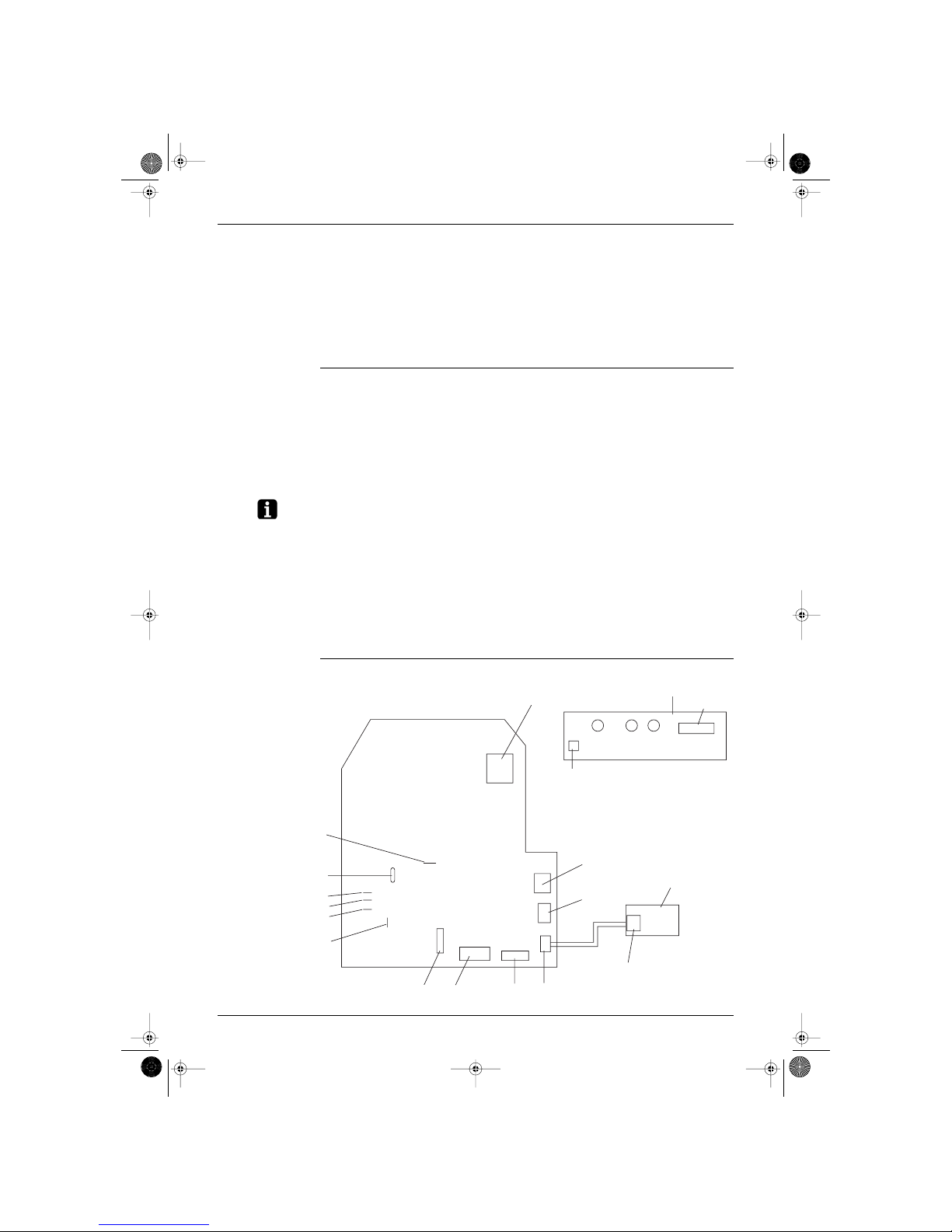
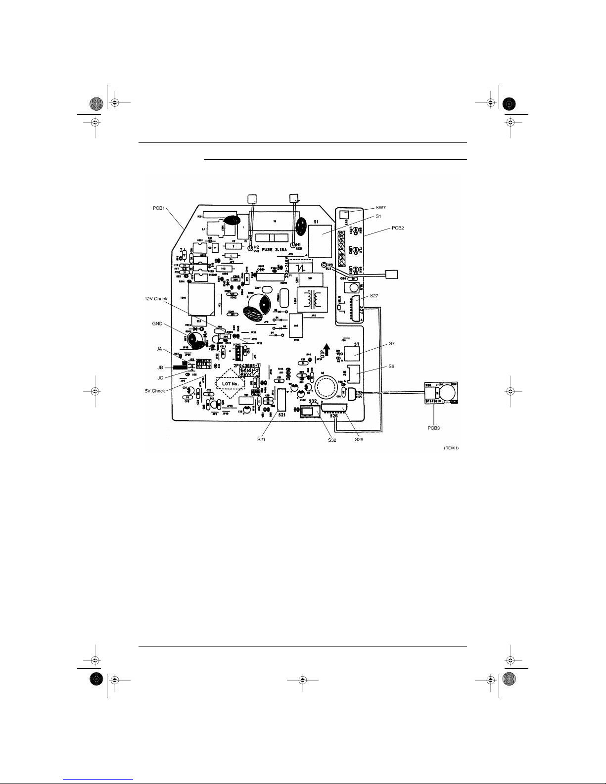
1.1 FTK25/35J Series, FTX25/35J Series
Printed circuit board (1) (Control PCB)
Printed circuit board (2) (Signal Receiver PCB)
Printed circuit board (3) (Intelligent Eye Sensor PCB)
Name of connector
Note: Other designations
Control PCB (1)
1) S1 Connector for fan motor
2) S6 Connector for swing motor (Horizontal Flap)
3) S7 Connector for fan motor
4) S21 Connector for centralized control to 5 rooms
5) S27, S36 Connector for control PCB
6) S26 Connector for signal receiver PCB
7) S32 Connector for room temp/Heat exchanger thermistor
8) S35 Connector for Intelligent Eye Sensor PCB
1) V1 Varistor
2) JA ADDRESS SETTING JAMPER
JB Fan speed setting when compressor is OFF on thermostat.
JC Power failure recovery function.
∗ Refer to page 121 for more detail.
3) SW7 OPERATION SWITCH
4) LED1 (GRN) LED for operation
5) LED2 (YLW) LED for timer
6) LED3 (GRN) LED for intelligent eye
(RL001)
Control P C B (1)
S1
Signal receive P C B (2)
S27
GRN
GRN
YLW
LED1 LED2 LED3
SW7
S7
S6
Intelligent eye
sensor P C B (3)
S36
S35
S26
S32
S21
5V check
Jamper
JA
JB
JC
ground
12V check
Jamper
Si-86.book Page 4 Friday, June 23, 2000 10:26 AM
SIE-86 Printed Circuit Board Connector Wiring Diagram and Name
Printed Circuit Board Connector Wiring Diagram 5
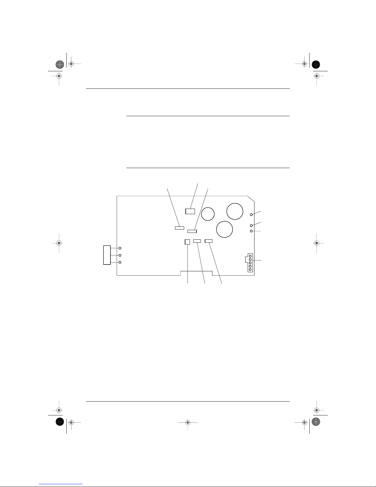
P.C.B (1) (Control P.C.B) Detail
Si-86.book Page 5 Friday, June 23, 2000 10:26 AM
Printed Circuit Board Connector Wiring Diagram and Name SIE-86
6 Printed Circuit Board Connector Wiring Diagram
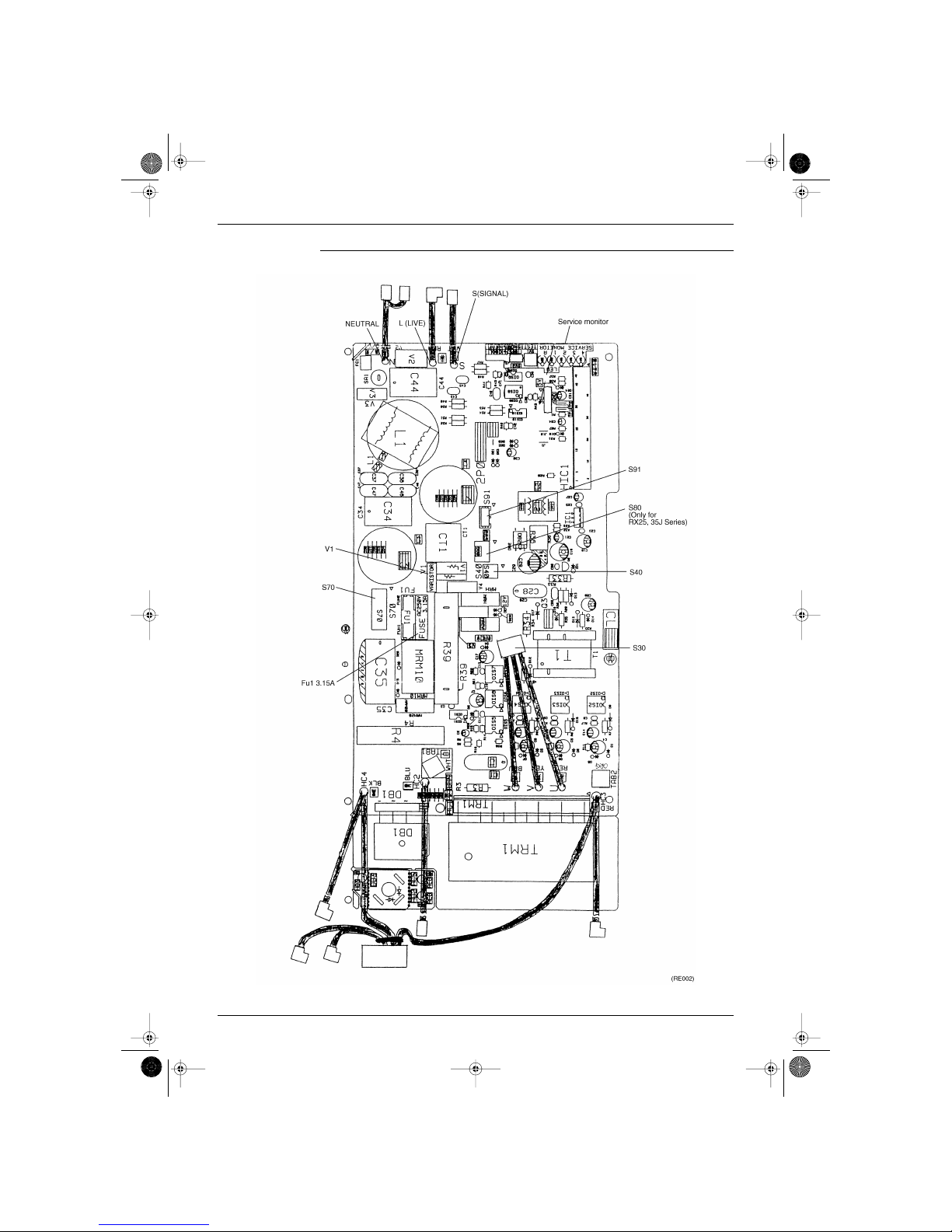
1.2 RK25/35J Series, RX25/35J Series
Printed circuit board (1) (Main-PCB)
Name of connector
PCB (1)
1) S30 Connector for compressor motor (with internal thermostat)
2) S70 Connector for fan motor
3) S80 Connector for 4 WAY VALVE COIL (RX25 · 35J Series only)
4) S91 Connector for THERMISTOR
5) S40 Connector for OL
6) SW1 NONE (Forced operation ON/OFF switch)
7) SW2 NONE (Forced operation Mode selector switch (H/P only))
S30
W
U
V
FU
S70
V1
Service
Monitor
S40 S80
S91
S(SIGNAL)
L(LIVE)
N(NEUTRAL)
(RL002)
Si-86.book Page 6 Friday, June 23, 2000 10:26 AM
SIE-86 Printed Circuit Board Connector Wiring Diagram and Name
Printed Circuit Board Connector Wiring Diagram 7
P.C.B (1) (Control P.C.B) Detail
Si-86.book Page 7 Friday, June 23, 2000 10:26 AM

Printed Circuit Board Connector Wiring Diagram and Name SIE-86
8 Printed Circuit Board Connector Wiring Diagram
Si-86.book Page 8 Friday, June 23, 2000 10:26 AM

SIE-86
Main Function 9
Part 3
Main Function
1. General Functionality ............................................................................10
1.1 Functions of Thermistors....................................................................... 10
1.2 Operating Modes................................................................................... 12
1.3 Frequency Principle............................................................................... 13
1.4 Defrost Control ...................................................................................... 15
1.5 Forced Operation Mode......................................................................... 16
1.6 Wide-angle Flaps, Diffuser, Louvres and Autoswing............................. 17
1.7 Fan Speed Control for Indoor Units....................................................... 19
1.8 Fan Speed Control for Outdoor Units.................................................... 20
1.9 General Functions ................................................................................. 21
1.10 Intelligent Eye (J type)........................................................................... 23
1.11 Good Sleep Cooling Control (J Type).................................................... 25
1.12 Automatic Operation.............................................................................. 26
1.13 Input Current Control (H / J Type) ......................................................... 27
1.14 Freeze Protection Function in Cooling. (H / J Type).............................. 28
1.15 Peak-Cut Control Function (H / J Type) ................................................ 29
1.16 Four-Way Valve Function Compensation (H / J Type).......................... 30
1.17 Compressor Protection Function (H / J Type) ....................................... 31
1.18 Wet Operation Protection (H / J Type) .................................................. 32
1.19 Dew Condensation Sweating Prevention Function (H / J type)............. 33
Si-86.book Page 9 Friday, June 23, 2000 10:26 AM
General Functionality SIE-86
10 Main Function
1. General Functionality
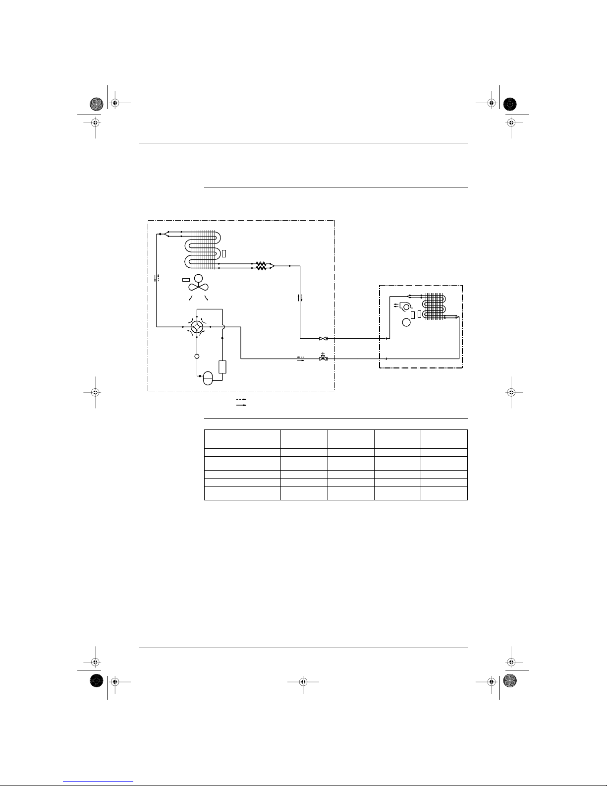
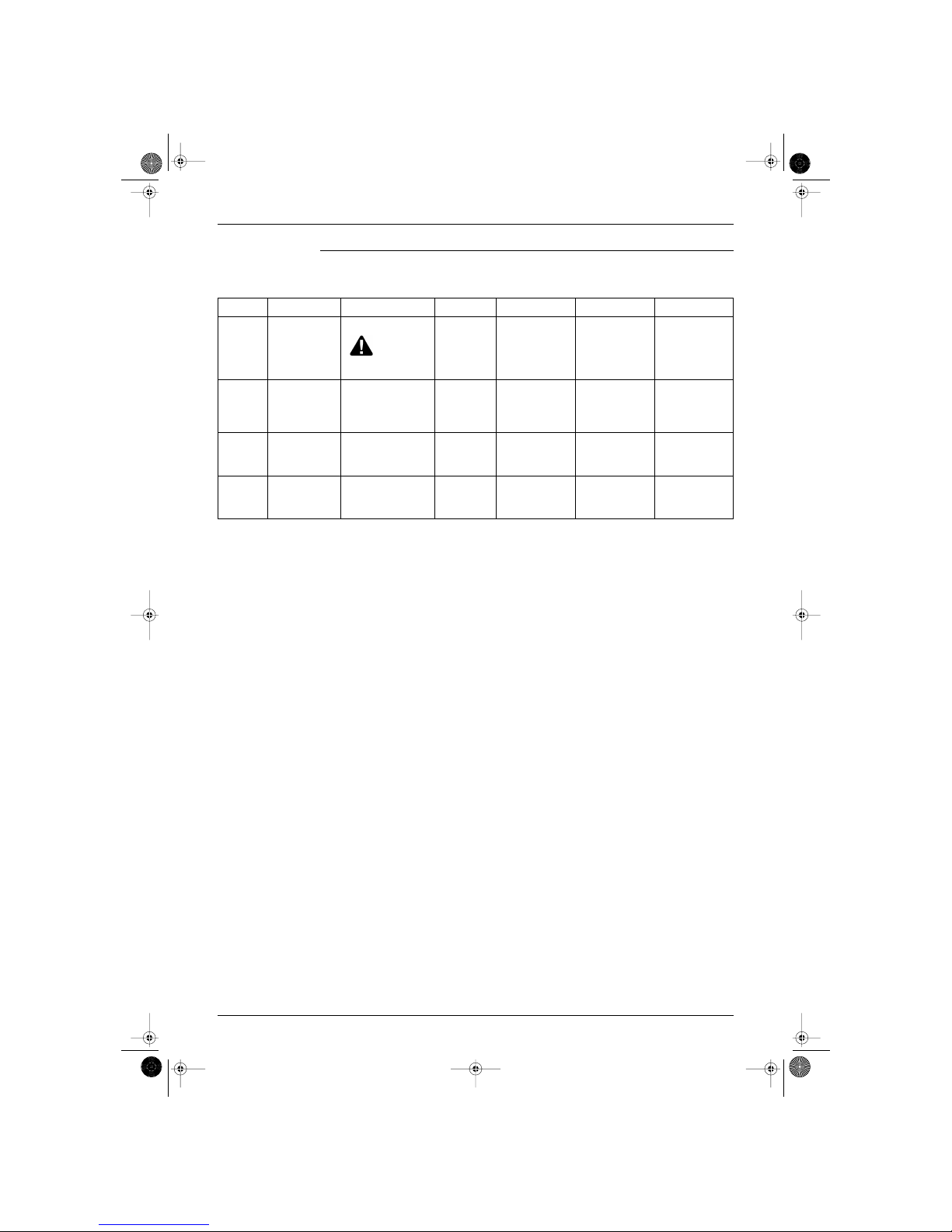
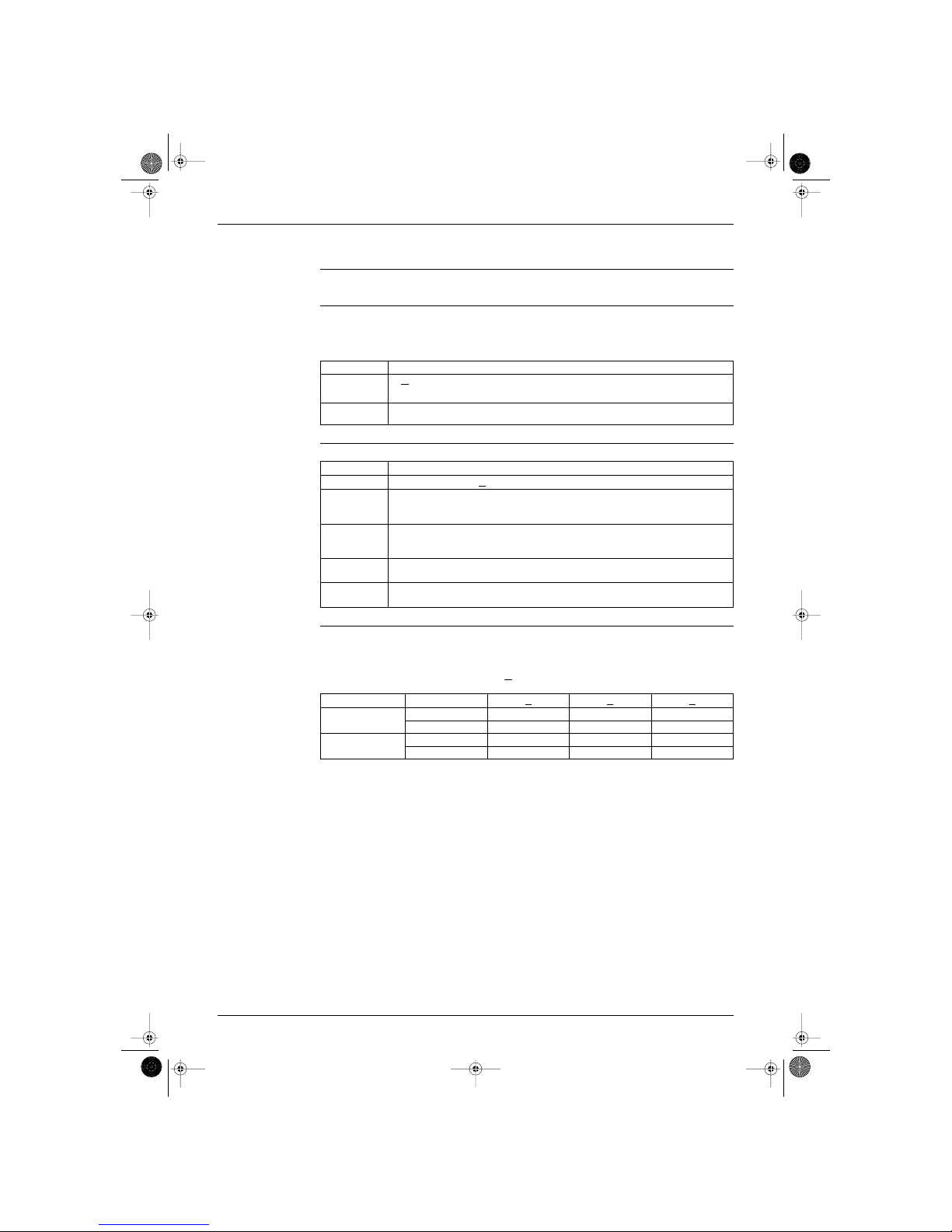
1.1 Functions of Thermistors
Location of
thermistors
The thermistors on the drawing below are used to control the system. This control secures a proper cooling
and prevents problems of the unit:
Frequency control The following table shows the thermistors that control the frequency:
with : available functions and — : no available functions.
OUTDOOR UNIT
M
COOLING
HEATING
FIELD PIPING
FIELD PIPING
R1T
R2T
INDOOR UNIT
R1T
R2T
M
(RE003)
Controls
Outdoor heat
exchanger
thermistor
Outdoor ambient
temperature
thermistor
Indoor ambient
temperature
thermistor
Indoor heat
exchanger
thermistor
Symbol R2T R1T R1T R2T
Freeze-up prevention. Refer to
page 11.
———
Peak cut off. Refer to page 11. — — —
Defrost. Refer to page 15. —
High pressure limitation in
heating. Refer to page 11.
——
Si-86.book Page 10 Friday, June 23, 2000 10:26 AM
SIE-86 General Functionality
Main Function 11
Frequency controlled functions
The following table shows the different functions, which are controlled by decreasing or increasing the
frequency:
Function
Sensor
Thermistor
Why? How? Set Reset Malfunction
Low outdoor
temperature
control
outdoor ambient
thermistor (R1T)
To avoid condensation in
cooling mode.
This control is
not executed when the unit
is in forced cooling mode or
in test mode.
By setting a high
frequency limit.
T
outdoor ambient
<
18˚C (J type)
25˚C (H type)
T
outdoor ambient
>
25˚C (J type)
33˚C (H type)
—
High
pressure
limitation in
heating
outdoor
temperature
thermistor (R1T)
indoor heat
exchanger
thermistor (R2T)
To control the pressure. By setting a high
frequency limit.
heating mode
T
outdoor
> 16 ˚C
T
indoor heat exchanger
> 22 ˚C
compressor on
compressor stop
timer delay (70 s)
has passed
—
Freeze-up
prevention
indoor heat
exchanger
thermistor (R2T)
To prevent the freezing up
of the indoor unit in cooling
mode.
By setting a high
frequency limit.
during cooling
0 ˚C <
T
indoor heat exchanger
< 8 ˚C
T
indoor heat exchanger
>
8 ˚C for 2 seconds
T
indoor heat exchanger
<
0 ˚C
(result: compressor
stop)
Peak cut off indoor heat
exchanger
thermistor (R2T)
To prevent an abnormal
high temperature on the
indoor heat exchanger in
heating mode.
By setting a high
frequency limit.
during heating
50 ˚C <
T
indoor heat exchanger
< 67 ˚C
T
indoor heat exchanger
<
50 ˚C for 2 seconds
T
indoor heat exchanger
>
67 ˚C
(result: compressor
stop)
Si-86.book Page 11 Friday, June 23, 2000 10:26 AM
General Functionality SIE-86
12 Main Function
1.2 Operating Modes
Modes There are two operating modes:
normal operating mode
forced operating mode.
Overview The following table shows the different control modes of the Split inverter room air conditioners:
Note: The outdoor unit retains the operating mode, when the thermostat is switched off.
Refer to “Pre-heat operation” on page 21
Mode Item
Normal operating mode Auto (Heat pump only)
Cooling
Dry keep
Heating (Including Automatic defrost)
Fan (for Cooling only)
Stop mode:
Pre-heat operation. Refer to “Pre-heat operation”.
Stop
Test Operation Forced cooling / heating
Forced operating mode Forced cooling
Si-86.book Page 12 Friday, June 23, 2000 10:26 AM
SIE-86 General Functionality
Main Function 13
1.3 Frequency Principle
Main control
parameters
The compressor is frequency-controlled during normal operation. The target frequency is set by the
following 2 parameters coming from the operating indoor unit:
the load condition of the operating indoor unit
the difference between the room temperature and the set temperature.
Additional control
parameters
The target frequency is adapted by additional parameters in the following cases:
frequency limits
initial settings
forced cooling/heating operation.
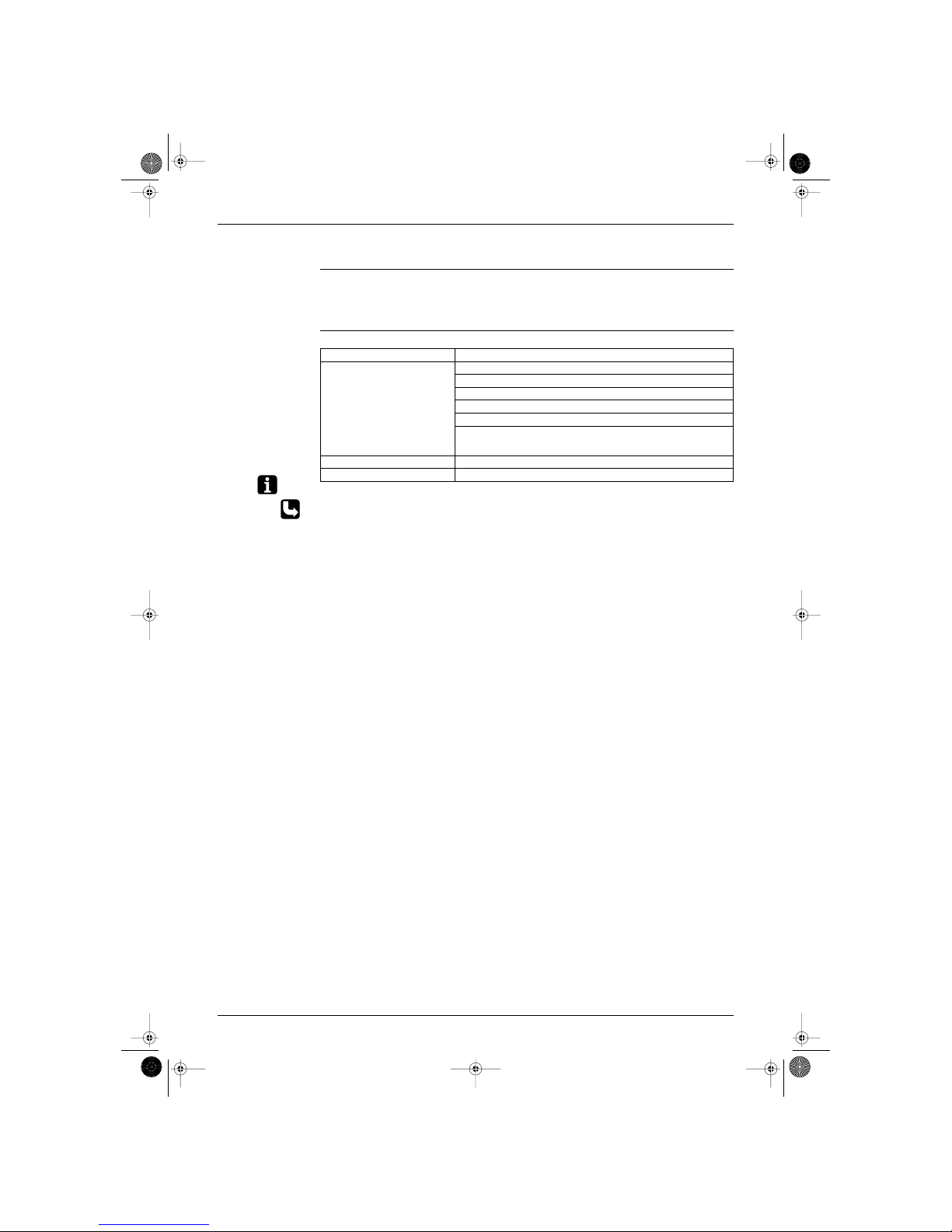
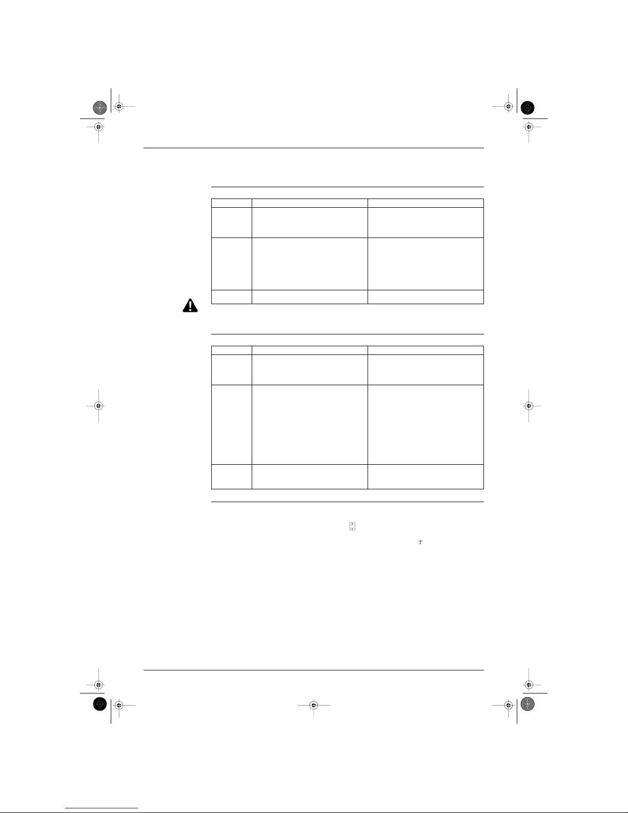
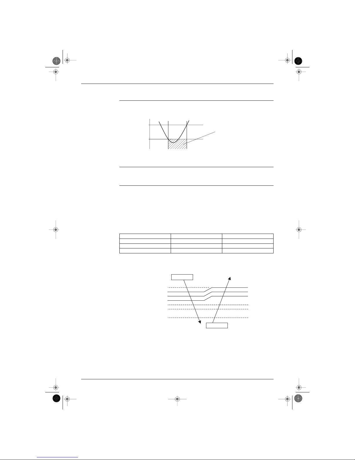
Inverter principle To regulate the capacity, a frequency control is needed. The inverter makes it possible to vary the rotation
speed of the compressor. The following table explains the conversion principle:
Drawing of inverter The following drawing shows a schematic view of the inverter principle:
Phase Description
1 The single phase power supply in AC is converted into DC.
2 The single phase power supply DC is converted into a three phase shopped DC voltage with a
variable frequency.
When the frequency increases, the rotation speed of the compressor increases resulting in an
increased refrigerant circulation. This leads to a higher amount of the heat exchange per unit.
When the frequency decreases, the rotation speed of the compressor decreases resulting in a
decreased refrigerant circulation. This leads to a lower amount of the heat exchange per unit.
Min. frequency A H type J type Max. frequency B H type J type
Cooling 36 34 Cooling 94 98
Heating 36 34 Heating 94 98
50 Hz
60 Hz
Refrigerant circulation rate (high)
Amount of heat
exchanged (large)
Amount of heat
exchanged (small)
AC
power
freq=cte
max. freq.=
A Hz
DC
power
Amount of heat
exchanged (large)
Amount of heat
exchanged (small)
high f
low f
min. freq.=
B Hz
freq=variable
capacity=
variable
Refrigerant circulation rate (low)
high speed
low speed
(RL003)
Si-86.book Page 13 Friday, June 23, 2000 10:26 AM
General Functionality SIE-86
14 Main Function
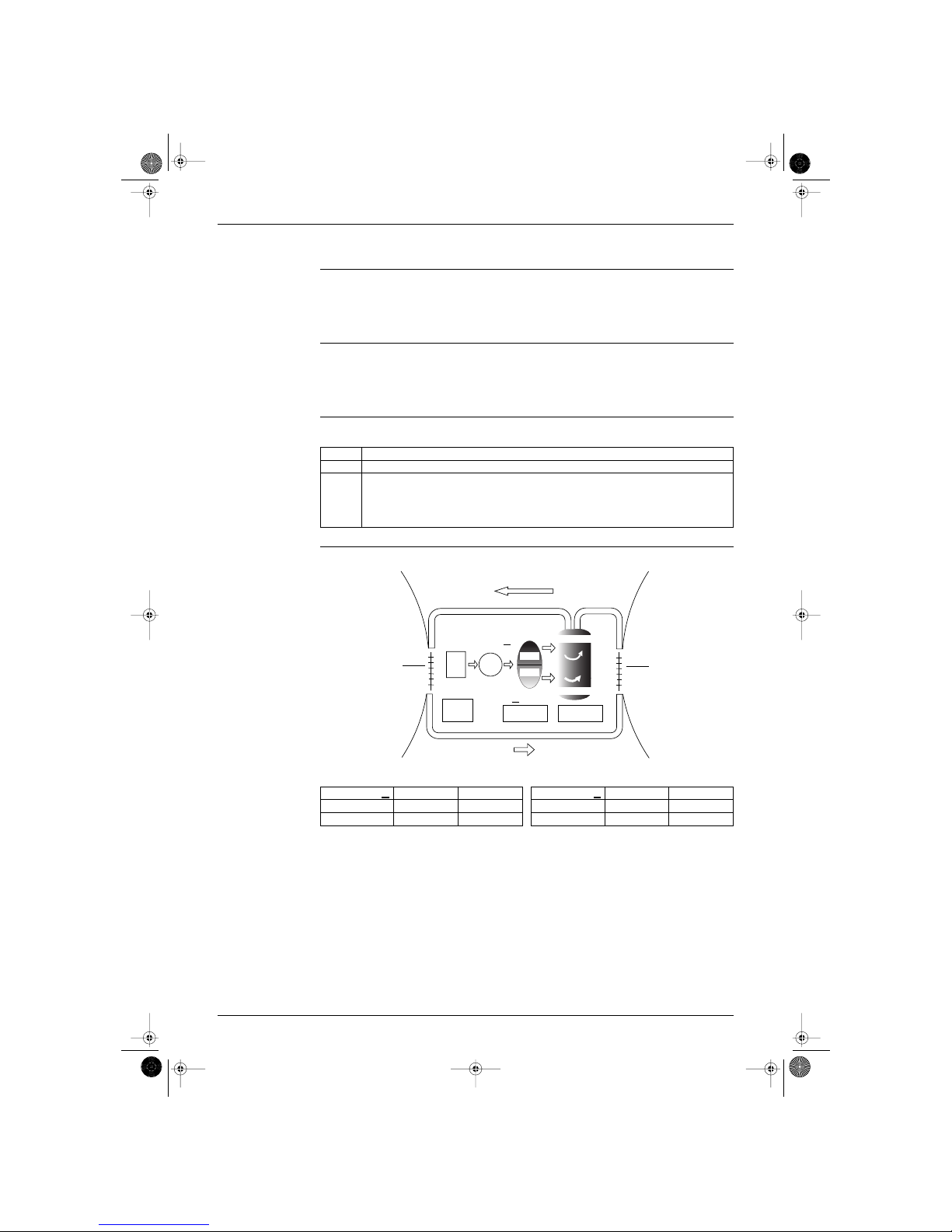
Inverter features The inverter provides the following features:
The regulating capacity can be changed according to the changes in the outside temperature and
cooling/heating load.
Quick heating and quick cooling
The compressor rotational speed is increased when starting the heating (or cooling). This enables a
quick set temperature.
Even during extreme cold weather, the high capacity is achieved. It is maintained even when the
outside temperature is 0˚C.
Comfortable air conditioning
A detailed adjustment is integrated to ensure a fixed room temperature. It is possible to air condition
with a small room temperature variation.
Energy saving heating and cooling
Once the set temperature is reached, the energy saving operation enables to maintain the room
temperature at low power.
Frequency limits The following table shows the functions that define the minimum and maximum frequency:
Forced cooling/
heating operation
For more information, refer to “Forced mode” on page 16.
60 120 300
45˚C
Air discharge
temperature
inverter
normal heat pump
Start seconds
(RG001)
Frequency limits Limited during the activation of following functions
Low four way valve operation compensation. Refer to page 30.
Wet Operation Protection Function. Refer to page 32.
High Input current control. Refer to page 27.
Compressor protection function. Refer to page 31.
low outdoor temperature control. Refer to page 11.
high pressure limitation. Refer to page 11.
peak cut off. Refer to page 11.
freeze-up prevention. Refer to page 11.
defrost control. Refer to page 15.
Si-86.book Page 14 Friday, June 23, 2000 10:26 AM
SIE-86 General Functionality
Main Function 15
1.4 Defrost Control
Principle Defrost control is carried out by reversing the cycle from heating to cooling.
Start conditions Defrost control is set by the following conditions:
during heating
More than 6 minutes after the compressor has started up
when condition 1 or 2 in the table below are applicable:
Conditions The following table shows the different conditions on which defrost control is based:
Stop conditions Defrost control is reset by the following conditions:
T
[heat exchanger]
> 4˚C if T
[ambient outdoor]
< 19˚C
T
[heat exchanger]
> 18˚C if T
[ambient outdoor]
< -3˚C
T
[heat exchanger]
> (-1˚C ∞ T
[ambient outdoor]
) + C if -3˚C < T
[ambient outdoor]
< 19˚C.
Condition Description
1
A minutes of accumulated runtime
not yet 90 minutes of accumulated runtime
condition 1 or 2 or 3 in the table below
2
90 minutes of accumulated runtime
condition 1 or 4 or 5 in the table below
Conditions Description
1 T
[outdoor heat exchanger]
< B˚C for 1 min.
2
T
[ambient outdoor]
< 5˚C
T
[outdoor heat exchanger]
< (-5 + T
[ambient outdoor]
∞ 0,4)
check if T
[indoor heat exchanger]
decreases 5 times every 10 seconds
3
T
[ambient outdoor]
≥ 5˚C
T
[outdoor heat exchanger]
< -3˚C
check if T
[indoor heat exchanger]
decreases 5 times every 10 seconds
4
T
[ambient outdoor]
< 5˚C for 60 seconds
T
[outdoor heat exchanger]
< (-5 + T
[ambient outdoor]
∞ 0,4) for 60 seconds
5
T
[ambient outdoor]
≥ 5˚C for 60 seconds
T
[outdoor heat exchanger]
< -3˚C for 60 seconds
Class
A B C
H type 25 32 -15 23
35 40 -15 17
J type 25 32 -15 17
35 32 -14 17
Si-86.book Page 15 Friday, June 23, 2000 10:26 AM
General Functionality SIE-86
16 Main Function
1.5 Forced Operation Mode
1.5.1 H type
Forced mode The following table explains the different forced operation modes, forced cooling and forced heating:
The protective functions overrule the forced mode. (H type only)
1.5.2 J type
Forced mode
A way to enter the test operation mode by a remote controller.
1. Set on the desirous mode and push ON/OFF button. (operation ON)
2. Two buttons; Center of temperature set buttons “ ”, and “ Mode” button, should be pushed
simultaneously. (then a left figure of the liquid crystal temperature’s display number starts to blink.)
3. Moreover, push “MODE” button twice. (If the liquid crystal display becomes “ ”, the test operation
mode will startup under the mode displayed in a liquid crystal. )
Item Forced cooling Forced heating
Conditions
not in the 3-minute stand-by mode
normal operation mode
outdoor unit off
no malfunction in the outdoor unit
forced mode: cooling mode.
not in the 3-minute stand-by mode
normal operation mode
outdoor unit off
no malfunction in the outdoor unit
forced mode: heating mode.
Start
Adjustment
(H type)
Press the forced operation switch SW1 to
start the following items:
command frequency: 66 Hz
timer: 60-minute
fan speed: H
swing flap: preservation of last setting
indoor adjustment: send forced mode to
unit.
Press the forced operation switch SW1
while short circuiting SW2 to start the
following items:
command frequency: 66 Hz
timer: 60-minute
fan speed: H
swing flap: preservation of last setting
indoor adjustment: send forced mode to
unit.
Reset
(H type)
Press the forced operation switch again or after
60 minutes.
Press the forced operation switch again or after
60 minutes.
Item Forced cooling Forced heating
Conditions
not in the 3-minute stand-by mode
normal operation mode
outdoor unit off
no malfunction in the outdoor unit
forced mode: cooling mode.
not in the 3-minute stand-by mode
normal operation mode
outdoor unit off
no malfunction in the outdoor unit
forced mode: heating mode.
Start
Adjustment
1. Keep pushing the operation switch of the
indoor unit for 5 to 10 seconds.
2. Change the remote controller setting to a
cooling test operation.
( Regarding a way to enter the test
operation, refer to the note in a margin
below)
Possible to enter the forced cooling mode by
either way of 1. or 2..
Fix operation frequency to 66 Hz.
Operation-on timer :15 min.
Indoor unit’s fan : H tap.
Swing flap: the latest set position.
With a change of the remote controller setting
to a heating test operation, the unit enters the
forced heating mode.
(Regarding a way to enter the test operation
mode, refer to the note in a margin below)
Fix operation frequency to 66 Hz.
Operation-on timer :15 min.
Indoor unit’s fan : H tap.
Swing flap: the latest set position.
Reset
1. Push the operation switch of the indoor unit
in an usual way.
2. Push the stop button on a remote controller.
3. Operation-on timer : 15 min. overtime.
1. Push the operation switch of the indoor unit
in an usual way.
2. Push the stop button on a remote controller.
3. Operation-on timer : 15 min. overtime.
TEMP
Si-86.book Page 16 Friday, June 23, 2000 10:26 AM

SIE-86 General Functionality
Main Function 17
1.6 Wide-angle Flaps, Diffuser, Louvres and Autoswing
1.6.1 H type
Wide-angle flap The large flaps send a large volume of air downwards to the floor. The flap provides an optimum control in
cooling, heating and dry mode.
Diffuser The diffuser enables the air coming out of the indoor unit to reach all surfaces in cooling mode.
Heating mode During heating mode, the large flap enables direct warm air straight downwards. The diffuser presses the
warm air above the floor to reach the entire room.
Cooling mode During cooling mode, the diffuser retracts into the indoor unit. This enables a distribution of cooled air
throughout the entire room.
Louvres The louvres, made of elastic synthetic resin, provide a wide range of airflow that guarantees a comfortable
air distribution.
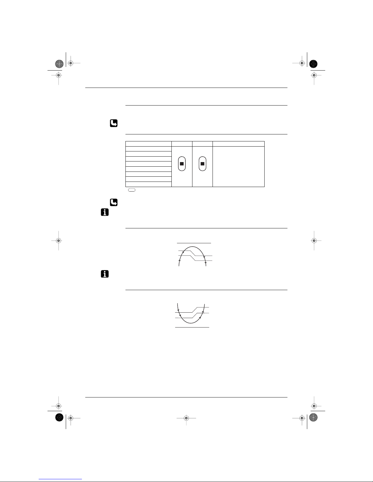
Autoswing The following table explains the autoswing process for heating and cooling:
Item Description Drawing
heating
The flap swings up and down as shown in
the drawing alongside.
cooling
The flap swings up and down as shown in
the drawing alongside.
(RL004)
(RL005)
Si-86.book Page 17 Friday, June 23, 2000 10:26 AM
General Functionality SIE-86
18 Main Function
1.6.2 J type
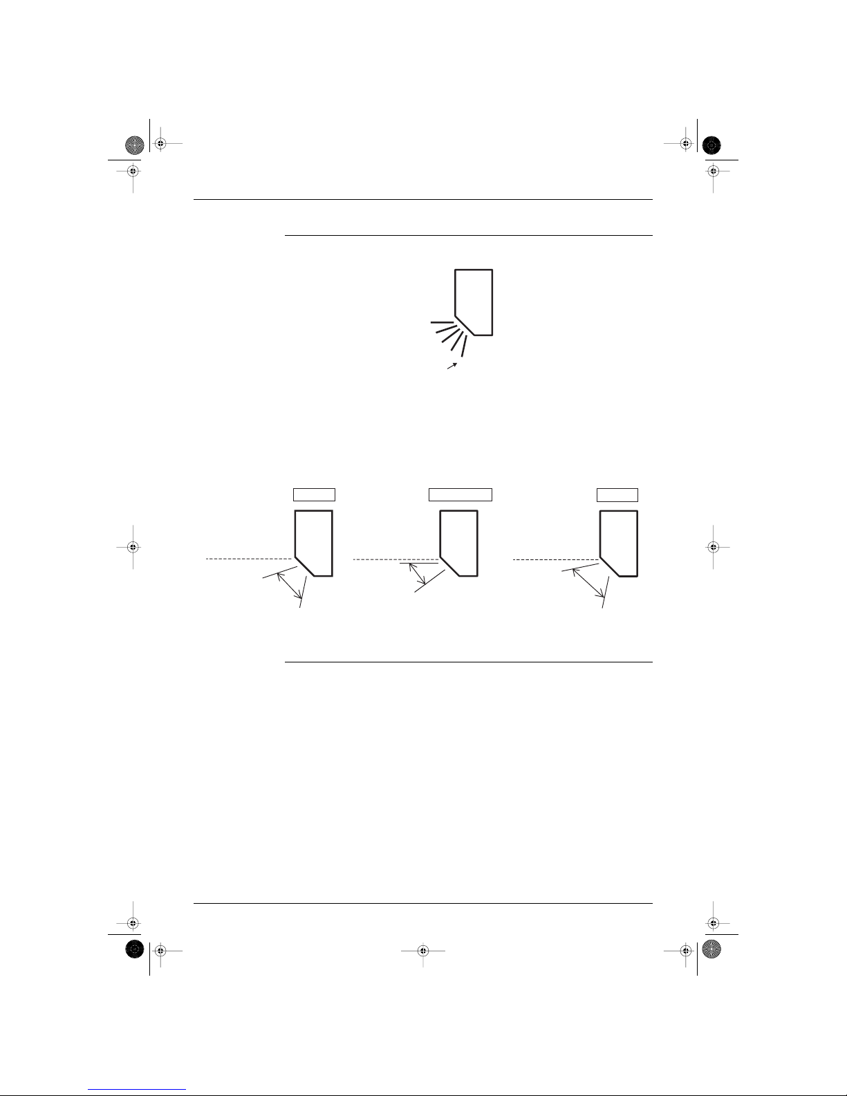
Outline of the
action
It can be commanded for J type by means of a user setting to select either any one desired position among
the five-step directions of air flow adjusted on a remote controller, or Auto-swing.
Although the liquid crystal display of the five-step directions of the air flow is common for the modes of
Cooling·Dry/Heating as illustrated above, in fact the range of the swing angle is slightly different in every
operation mode.
The position a user set will be selected among the five positions calculated through the preliminary and
evenly divided into four partitions which were taken from the upper and lower flap angle’s range limits of
each mode.
When Auto-swing is chosen, the flap swings in the swing range which meets the operation mode selected.
Others The vertical louver can be adjusted manually. The movable range is 60 degrees for left or right, and
total 120 degrees.
A diffuser is not available for J type.
1
2
3
4
5
Initial
(RL006)
∗ Fan mode is available for the models of cooling-only.
20˚
45˚
Heating mode
0 degree based on
the horizontal line.
(RL007)
0˚
25˚
Cooling /Dry mode
0 degree based on
the horizontal line.
(RL008)
10˚
45˚
0 degree based on
the horizontal line.
Fan mode
(RL009)
Si-86.book Page 18 Friday, June 23, 2000 10:26 AM
SIE-86 General Functionality
Main Function 19
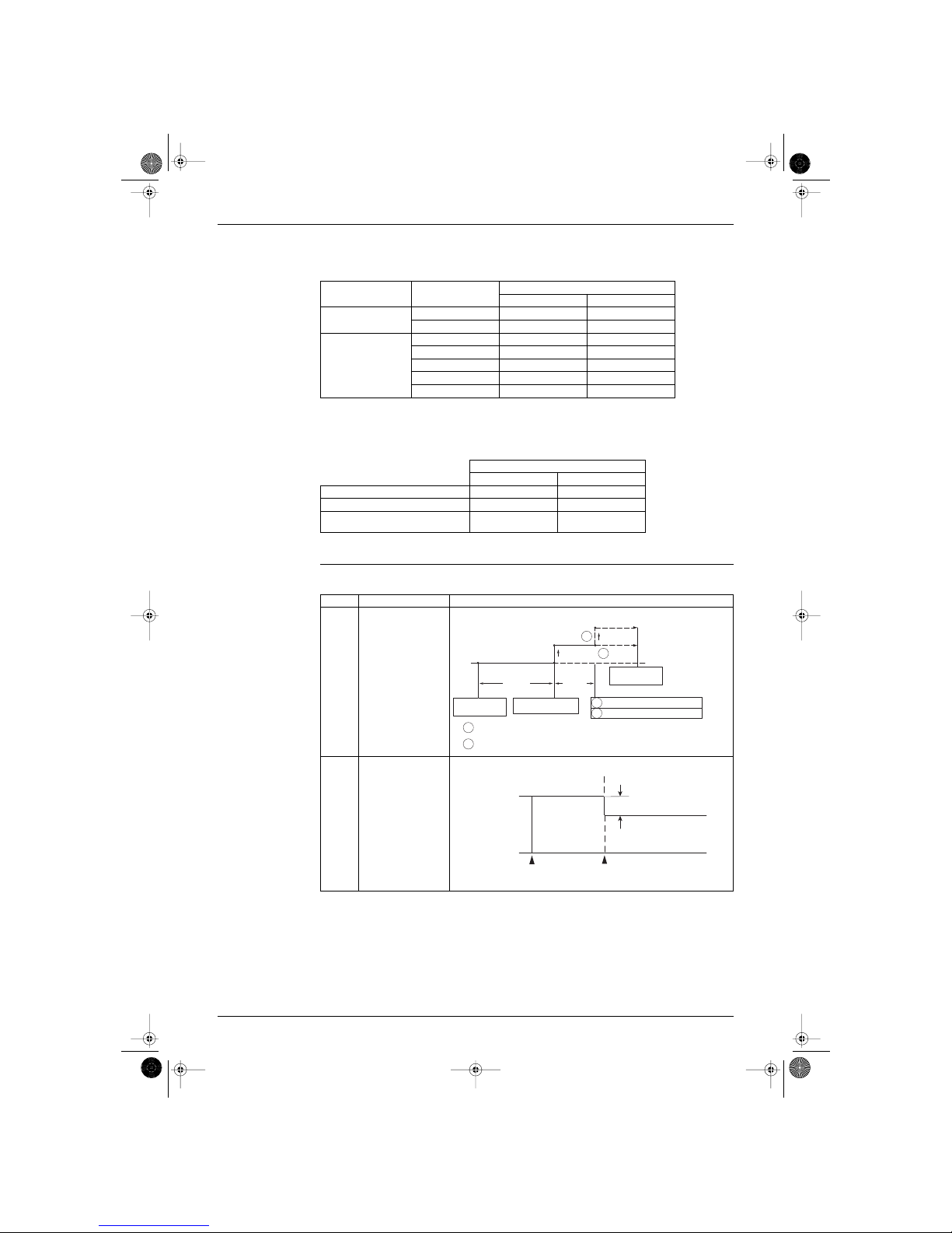
1.7 Fan Speed Control for Indoor Units
Control mode The airflow rate can be automatically controlled depending on the difference between the set temperature
and the room temperature. This is done through phase control and Hall IC control.
For more information about Hall IC, refer to ‘Hall IC check (A6)’ on page 61.
Phase steps Phase control and fan speed control contains 8 steps: LLL, LL, L, ML, M, HM, H and HH.
= Within this range the airflow rate is automatically controlled when the AIRFLOW ADJUSTING
button is set to AUTOMATIC
Refer to automatic airflow rate control on page 19.
Note: 1. During powerful operation, fan operate H tap + 50 - 70 rpm.
2. Fan stops during defrost operation.
Automatic air flow
control for heating
The following drawing explains the principle for fan speed control for heating:
Note: When there is no operation and the night set mode turns on, the step is low. Refer to “Night set mode” on
page 22.
Automatic air flow
control for cooling
The following drawing explains the principle of fan speed control for cooling:
Step Cooling Heating Dry mode
LLL (Heating thermostat OFF) H type : 500 - 860 rpm
(During powerful operation :
850 - 910 rpm)
J type : 800 - 980 rpm
(During powerful operation :
1050 rpm)
LL (Cooling thermostat OFF)
L
ML
M
MH
H
HH (Powerful)
(RL010)
(RL010)
-1.5˚C
-0.5˚C
-1˚C
-2˚C
L
ML
M
Thermostat
setting
temperature
Phase control
Temperature difference between
ambient and set temperature
fan speed
(RL012)
+1.5˚C
+0.5˚C
+2˚C
+1˚C
M
ML
L
fan speed
Temperature difference between
ambient and set temperature
Phase control
Thermostat
setting
temperature
(RL013)
Si-86.book Page 19 Friday, June 23, 2000 10:26 AM

General Functionality SIE-86
20 Main Function
1.8 Fan Speed Control for Outdoor Units
Control The following drawing explains the fan speed control:
Fan off delay When the compressor turns off and T
[outdoor ambient]
> D˚C, the outdoor fan stays running at the same
speed for
E seconds.
ON
OFF
A˚C
B˚C
For ambient temperature
between C˚C.
outdoor heat exchanger temperature
(RL014)
A (˚C) B (˚C) C (˚C) D (˚C) E (sec)
H type 28 34 0 - 18 10 30
J type 33 39 0 - 9 10 60
Caution
∗ J type operates the outdoor unit fans in the cooling mode even at the condition that a compressor is
not operated. (In case of existing model H series, the outdoor unit fans stops at the condition that a
compressor is not operated.)
Si-86.book Page 20 Friday, June 23, 2000 10:26 AM
SIE-86 General Functionality
Main Function 21
1.9 General Functions
Pre-heat operation When the equipment has stopped and t
[outside]
< 11.5˚C, the compressor is warmed-up by passing a
single-phase (U, V phase) current through the compressor motor to speed up the start. The power
consumption is 30-40W.
∗ For both H / J type
Hot start function During defrosting or when the thermostat is on in heating mode, the indoor heat exchanger temperature
≥ 29˚C to fan starts to avoid cold draft.
Dry mode The dry mode removes humidity while maintaining the room temperature. The temperature and fan cannot
be regulated during dry mode.
<Management>
1. Decision of the dry setting temperature
When entering the following dry mode,
1 Stop → an operation will start with Dry.
2 Mode except Dry → changing to dry mode
Thermostat ON/OFF point is decided in accordance with the following conditions.
2. Frequency command
The frequency command is decided based on a room temperature zone.
The room temperature zone is decided as follows.
11.5˚C
13.5˚C
Outside
temperature
OFF ON OFF
warm-up
control for
compressor
(RL015)
Room temp. cond. at entering Dry. Set temp. (thermostat ON) Thermostat OFF temp.
24˚C ≤ Room temp. Room temp. at the entering. Room temp. -2˚C at the entering.
18˚C ≤ Room temp. < 24˚C Room temp. at the entering. Room temp. -1.5˚C at the entering.
Room temp. < 18˚C18˚C17˚C
Room temp. - setting temp.
Room temp.
zone
1.0
Room temp.
zone
F
0.5 F
E
0E
D
-0.5 D B
-1
-1.5
Thermostat OFF point
dTmpOff
B
AA
at falling temp.
at rising temp.
(RL016)
Si-86.book Page 21 Friday, June 23, 2000 10:26 AM
General Functionality SIE-86
22 Main Function
The frequency command for every zone is stated below.
(Please note that an operation will not carry out in the commanded frequency sometimes in case a
protection control like a freeze-protection etc. will be actuated.)
3. Required fan speed
Fan speed changes the rotation speed every time when a thermostat switches over ON and OFF.
When the thermostat becomes Off, fan continues to operate 10 minutes more with low speed so as to
prevent recovery of humidity caused by reevaporation of the drain water, and then stops.
∗ For both H / J type
Night set mode The night set mode is activated when the off timer is set. It restricts the operation frequency, to minimize
the noise.
∗ For both H / J type
Room temperature Room temp. zone
Command frequency
H type (25 / 35) J type (25 / 35)
Room temp. < 18˚C
A 0 / 0Hz 0 / 0Hz
except A 36 / 36Hz 34 / 34Hz
Room temp. ≥ 18˚C
A 0 / 0Hz 0 / 0Hz
B 36 / 36Hz 34 / 34Hz
D 36 / 36Hz 40 / 40Hz
E 40 / 40Hz 42 / 42Hz
F 40 / 44Hz 42 / 42Hz
Fan rpm (thermostat ON)
H type (25 / 35) J type (25 / 35)
Thermostat ON 800 / 800rpm 970 / 980rpm
Thermostat OFF 700 / 700rpm 800 / 800rpm
Thermostat ON and dry on powerful
operation
850 / 910rpm 1050 / 1050rpm
Item Description Drawing
cooling The set temperature
stays on for one hour,
then decreases slightly
for economical
operation.
heating The set temperature
stays on for one hour,
then increases slightly
for economical
operation.
0,5˚C
0,5˚C
0,5˚C
temperature shift
A
A
B
B
A
B
temperature setting +1˚C
temperature setting +0.5˚C
temperature setting
operation stops
at the set hours
1 hour
30 min.
Timer operation
Night set circuit on
+0.5˚C temperature shift
Temperature setting remains
When the outside temperature is lower than 27˚C and the room
temperature is at the set temperature.
When the outside temperature is 27˚C or higher.
(RL017)
2˚C
Thermostat
setting
Timer operation
Night set circuit on
1 hour later
(RL018)
Si-86.book Page 22 Friday, June 23, 2000 10:26 AM
 Loading...