

Daikin RX09RMVJU, FDMQ09RVJU, FDMQ18RVJU, FDMQ24RVJU, RX15RMVJU Service Manual
...
Service
Manual
SiUS091628EA
Inverter Pair
Ceiling Mounted Cassette Type
FFQ-Q Series
[Applied Models]
z Inverter Pair : Heat Pump

zHeat Pump
Indoor Unit
FFQ09Q2VJU
FFQ12Q2VJU
FFQ15Q2VJU
FFQ18Q2VJU
SiUS091628EA
Inverter Pair
Ceiling Mounted
Cassette Type
FFQ-Q Series
Outdoor Unit
RX09QMVJU
RX12QMVJU
RX15QMVJU
RX18QMVJU
i Table of Contents

SiUS091628EA
1. Safety Cautions........................................................................................... v
1.1 Warnings and Cautions Regarding Safety of Workers ................................. v
1.2 Warnings and Cautions Regarding Safety of Users....................................vii
2. Icons Used ..................................................................................................x
Part 1 List of Functions ................................................................... 1
1. Functions.....................................................................................................2
Part 2 Specifications ....................................................................... 3
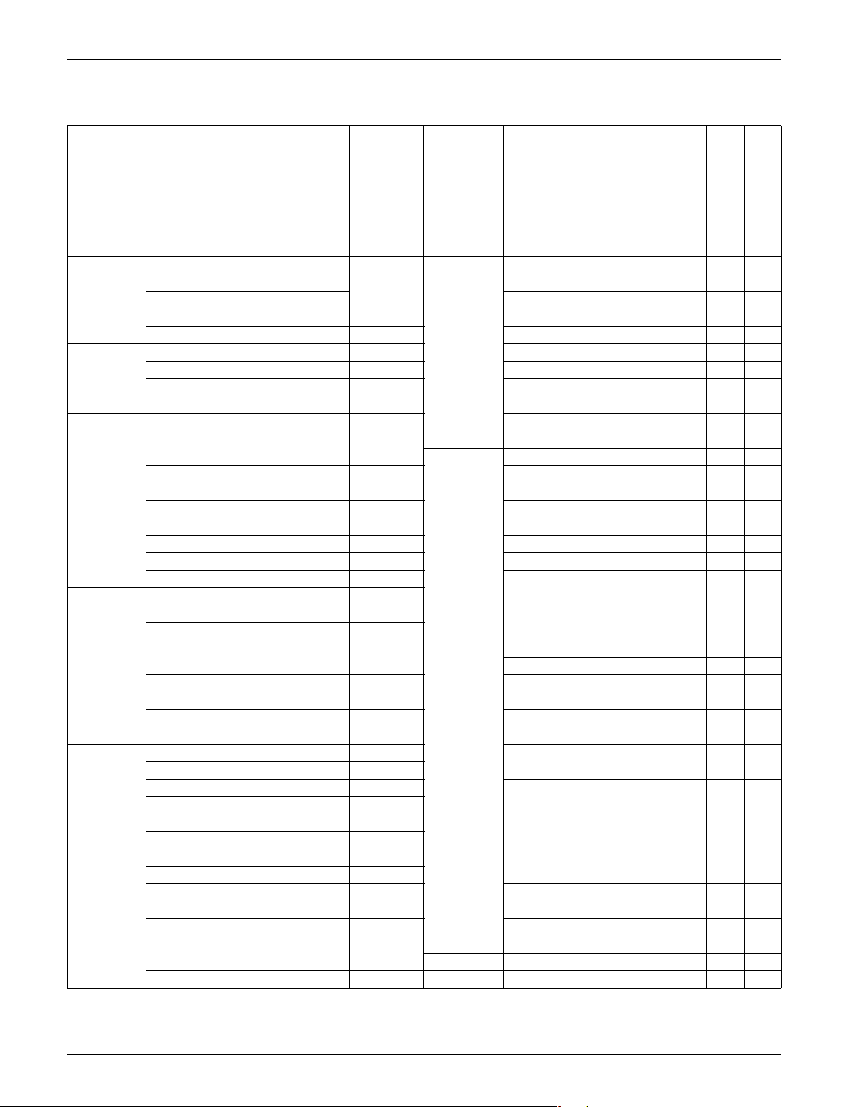
1. Specifications ..............................................................................................4
Part 3 Printed Circuit Board Connector Wiring Diagram ................6
1. Indoor Unit...................................................................................................7
1.1 FFQ09/12/15/18Q2VJU................................................................................ 7
2. Wired Remote Controller.............................................................................8
2.1 BRC1E73 ..................................................................................................... 8
3. Wireless Remote Controller Kit ...................................................................9
3.1 BRC082A41W, BRC082A42W(S) ................................................................ 9
4. Outdoor Unit..............................................................................................10
4.1 RX09/12QMVJU......................................................................................... 10
4.2 RX15/18QMVJU......................................................................................... 11
Part 4 Functions and Control......................................................... 12
1. Main Functions..........................................................................................13
1.1 Temperature Control .................................................................................. 13
1.2 Frequency Principle.................................................................................... 13
1.3 Airflow Direction Control............................................................................. 15
1.4 Fan Speed Control for Indoor Unit ............................................................. 15
1.5 Program Dry Operation .............................................................................. 16
1.6 Clock and Calendar Setting
(With Wired Remote Controller BRC1E73) ................................................ 17
1.7 Schedule TIMER Operation
(With Wired Remote Controller BRC1E73) ................................................ 19
1.8 Setback Function
(With Wired Remote Controller BRC1E73) ................................................ 23
1.9 Drain Pump Control .................................................................................... 23
1.10 Hot Start Control (In Heating Operation Only)............................................ 25
1.11 Presence and Floor Sensors (Option) ........................................................ 26
1.12 Other Functions.......................................................................................... 29
2. Control Specification .................................................................................30
2.1 Mode Hierarchy .......................................................................................... 30
2.2 Frequency Control ...................................................................................... 31
2.3 Controls at Mode Changing/Start-up.......................................................... 33
2.4 Discharge Pipe Temperature Control......................................................... 35
Table of Contents ii

SiUS091628EA
2.5 Input Current Control .................................................................................. 36
2.6 Freeze-up Protection Control ..................................................................... 37
2.7 Heating Peak-cut Control ........................................................................... 37
2.8 Outdoor Fan Control................................................................................... 38
2.9 Liquid Compression Protection Function.................................................... 38
2.10 Defrost Control ........................................................................................... 39
2.11 Electronic Expansion Valve Control ........................................................... 40
2.12 Malfunctions ............................................................................................... 43
Part 5 Remote Controller ............................................................... 44
1. Wired Remote Controller (BRC1E73) .......................................................45
2. Wireless Remote Controller Kit (BRC082A41W, BRC082A42W(S)) ........51
Part 6 Service Diagnosis................................................................ 53
1. General Problem Symptoms and Check Items .........................................55
2. Troubleshooting with LED .........................................................................56
2.1 Indoor Unit.................................................................................................. 56
2.2 Outdoor Unit ............................................................................................... 56
3. Service Diagnosis .....................................................................................57
3.1 Wired Remote Controller (BRC1E73) ........................................................ 57
3.2 Wireless Remote Controller Kit (BRC082A41W, BRC082A42W(S)) ......... 59
4. Troubleshooting ........................................................................................63
4.1 Error Codes and Description ...................................................................... 63
4.2 Indoor Unit PCB Abnormality ..................................................................... 64
4.3 Drain Level Control System Abnormality.................................................... 65
4.4 Indoor Fan Motor (DC Motor) or Related Abnormality ............................... 66
4.5 Humidifier or Related Abnormality.............................................................. 68
4.6 Thermistor or Related Abnormality............................................................. 69
4.7 Presence Sensor or Floor Sensor Abnormality .......................................... 70
4.8 Remote Controller Thermistor Abnormality ................................................ 71
4.9 Signal Transmission Error
(Between Indoor Unit and Remote Controller) ........................................... 72
4.10 Signal Transmission Error
(Between MAIN Remote Controller and SUB Remote Controller) ............. 73
4.11 Low-voltage Detection or Over-voltage Detection...................................... 74
4.12 Signal Transmission Error (Between Indoor Unit and Outdoor Unit).......... 76
4.13 Mismatching of Indoor Unit and Outdoor Unit ............................................ 78
4.14 Outdoor Unit PCB Abnormality................................................................... 79
4.15 OL Activation (Compressor Overload) ....................................................... 80
4.16 Compressor Lock ....................................................................................... 82
4.17 DC Fan Lock (Outdoor Fan Motor)............................................................. 83
4.18 Input Overcurrent Detection ....................................................................... 84
4.19 Four Way Valve Abnormality ...................................................................... 85
4.20 Discharge Pipe Temperature Control......................................................... 87
4.21 High Pressure Control in Cooling ............................................................... 88
iii Table of Contents

SiUS091628EA
4.22 System Shutdown due to Compressor Internal Temperature
Abnormality ................................................................................................ 90
4.23 Compressor System Sensor Abnormality .................................................. 91
4.24 Position Sensor Abnormality ...................................................................... 92
4.25 Thermistor or Related Abnormality (Outdoor Unit)..................................... 94
4.26 Electrical Box Temperature Rise................................................................ 96
4.27 Radiation Fin Temperature Rise ................................................................ 97
4.28 Output Overcurrent Detection .................................................................... 98
5. Check ......................................................................................................100
5.1 Thermistor Resistance Check .................................................................. 100
5.2 Indoor Fan Motor Connector Output Check ............................................. 101
5.3 Power Supply Waveforms Check ............................................................. 101
5.4 Electronic Expansion Valve Check........................................................... 102
5.5 Four Way Valve Performance Check ....................................................... 103
5.6 Inverter Unit Refrigerant System Check................................................... 103
5.7 Inverter Analyzer Check ........................................................................... 104
5.8 Rotation Pulse Check on the Outdoor Unit PCB ...................................... 106
5.9 Installation Condition Check ..................................................................... 107
5.10 Discharge Pressure Check....................................................................... 107
5.11 Outdoor Fan System Check ..................................................................... 108
5.12 Main Circuit Short Check.......................................................................... 108
5.13 Power Module Check ............................................................................... 110
Part 7 Trial Operation and Field Settings.................................... 112
1. Pump Down Operation............................................................................113
2. Forced Cooling Operation.......................................................................114
3. Trial Operation ........................................................................................115
4. Field Settings ..........................................................................................118
4.1 How to Change the Field Settings ............................................................ 118
4.2 Overview of the Field Settings.................................................................. 121
4.3 MAIN/SUB Setting when Using 2 Wired Remote Controllers................... 122
4.4 Address and MAIN/SUB Setting for Wireless Remote Controller ............ 123
4.5 Facility Setting (cooling at low outdoor temperature) ............................... 125
5. Silicone Grease on Power Transistor/Diode Bridge................................126
Part 8 Appendix............................................................................127
1. Piping Diagrams......................................................................................128
1.1 Indoor Unit................................................................................................ 128
1.2 Outdoor Unit ............................................................................................. 129
2. Wiring Diagrams......................................................................................130
2.1 Indoor Unit................................................................................................ 130
2.2 Outdoor Unit ............................................................................................. 131
3. Operation Limit........................................................................................133
Table of Contents iv
Safety Cautions SiUS091628EA
1. Safety Cautions
Be sure to read the following safety cautions before conducting repair work.
After the repair work is complete, be sure to conduct a test operation to ensure that the equipment
operates normally, and explain the cautions for operating the product to the customer.
Caution Items The caution items are classified into Warning and Caution. The Warning items are
especially important since death or serious injury can result if they are not followed closely. The
Caution items can also lead to serious accidents under some conditions if they are not
followed. Therefore, be sure to observe all the safety caution items described below.
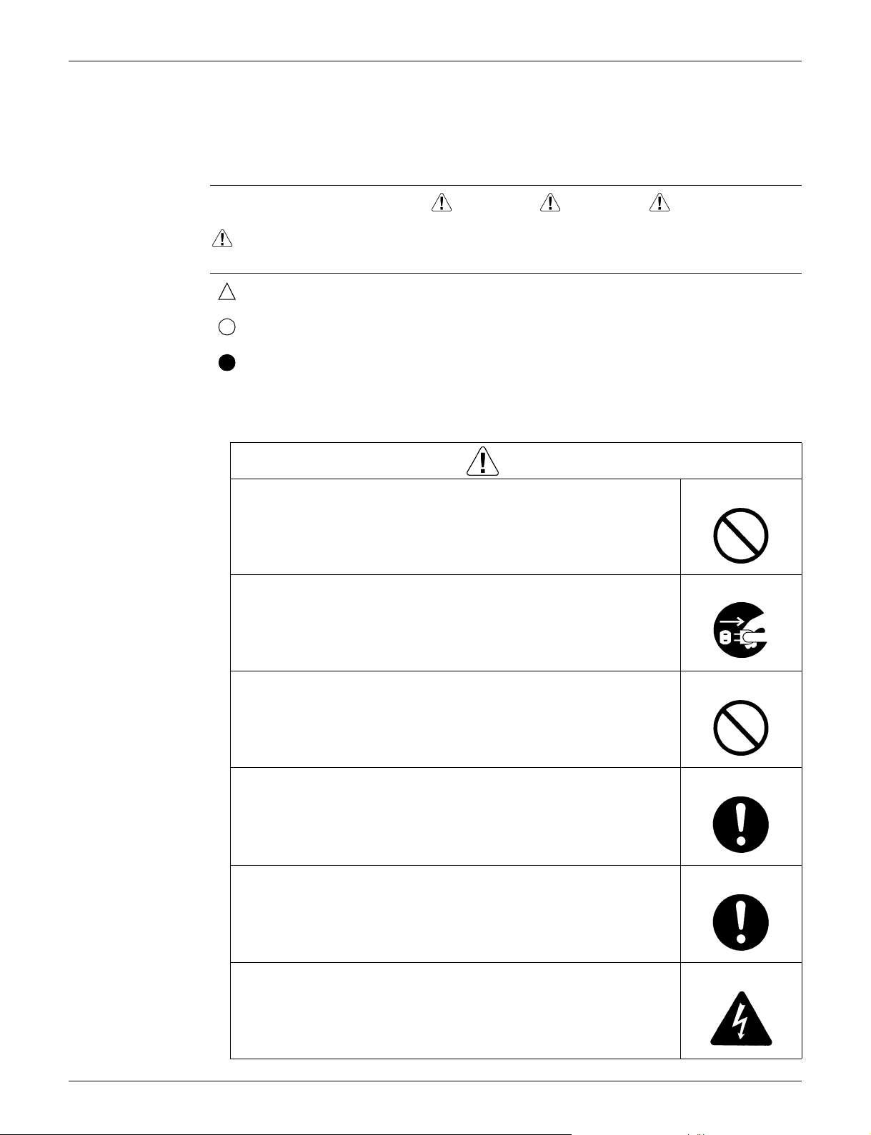
Pictograms This symbol indicates an item for which caution must be exercised.
The pictogram shows the item to which attention must be paid.
This symbol indicates a prohibited action.
The prohibited item or action is shown in the illustration or near the symbol.
This symbol indicates an action that must be taken, or an instruction.
The instruction is shown in the illustration or near the symbol.
1.1 Warnings and Cautions Regarding Safety of Workers
Warning
Do not store equipment in a room with fire sources (e.g., naked flames,
gas appliances, electric heaters).
Be sure to disconnect the power cable from the socket before
disassembling equipment for repair.
Working on equipment that is connected to the power supply may cause an
electrical shock.
If it is necessary to supply power to the equipment to conduct the repair or
inspect the circuits, do not touch any electrically charged sections of the
equipment.
If refrigerant gas is discharged during repair work, do not touch the
discharged refrigerant gas.
Refrigerant gas may cause frostbite.
When disconnecting the suction or discharge pipe of the compressor at
the welded section, evacuate the refrigerant gas completely at a wellventilated place first.
If there is gas remaining inside the compressor, the refrigerant gas or
refrigerating machine oil discharges when the pipe is disconnected, and it may
cause injury.
If refrigerant gas leaks during repair work, ventilate the area.
Refrigerant gas may generate toxic gases when it contacts flames.
Be sure to discharge the capacitor completely before conducting repair
work.
The step-up capacitor supplies high-voltage electricity to the electrical
components of the outdoor unit.
A charged capacitor may cause an electrical shock.
v

SiUS091628EA Safety Cautions
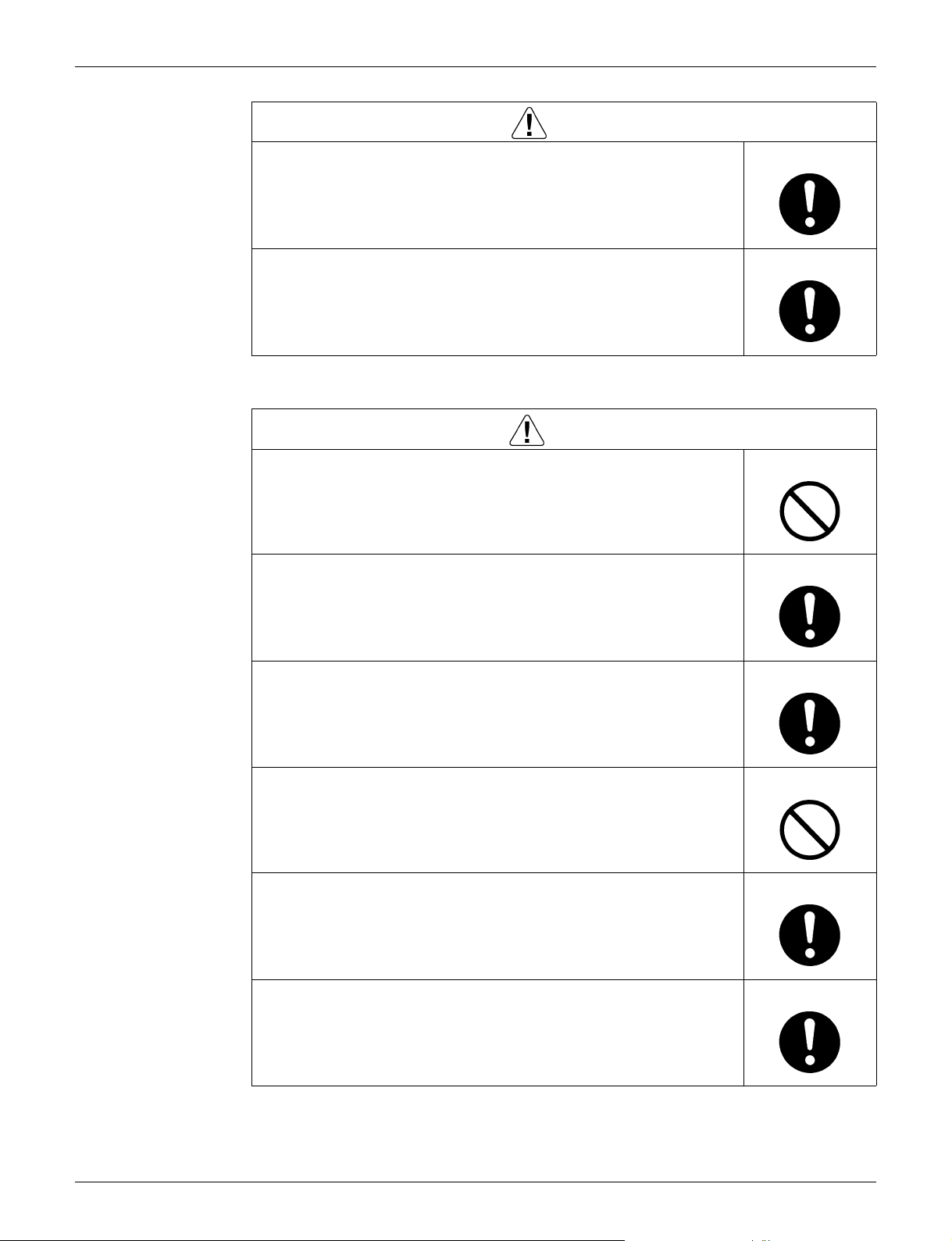
Warning
Do not turn the air conditioner on or off by plugging in or unplugging the
power cable.
Plugging in or unplugging the power cable to operate the equipment may cause
an electrical shock or fire.
Be sure to wear a safety helmet, gloves, and a safety belt when working
in a high place (more than 2 m (6.5 ft)).
Insufficient safety measures may cause a fall.
In case of R-32 / R-410A refrigerant models, be sure to use pipes, flare
nuts and tools intended for the exclusive use with the R-32 / R-410A
refrigerant.
The use of materials for R-22 refrigerant models may cause a serious accident,
such as a damage of refrigerant cycle or equipment failure.
Do not mix air or gas other than the specified refrigerant (R-32 / R-410A /
R-22) in the refrigerant system.
If air enters the refrigerant system, an excessively high pressure results,
causing equipment damage and injury.
Caution
Do not repair electrical components with wet hands.
Working on the equipment with wet hands may cause an electrical shock.
Do not clean the air conditioner with water.
Washing the unit with water may cause an electrical shock.
Be sure to provide an earth / grounding when repairing the equipment in
a humid or wet place, to avoid electrical shocks.
Be sure to turn off the power switch and unplug the power cable when
cleaning the equipment.
The internal fan rotates at a high speed, and may cause injury.
Be sure to conduct repair work with appropriate tools.
The use of inappropriate tools may cause injury.
vi
Safety Cautions SiUS091628EA
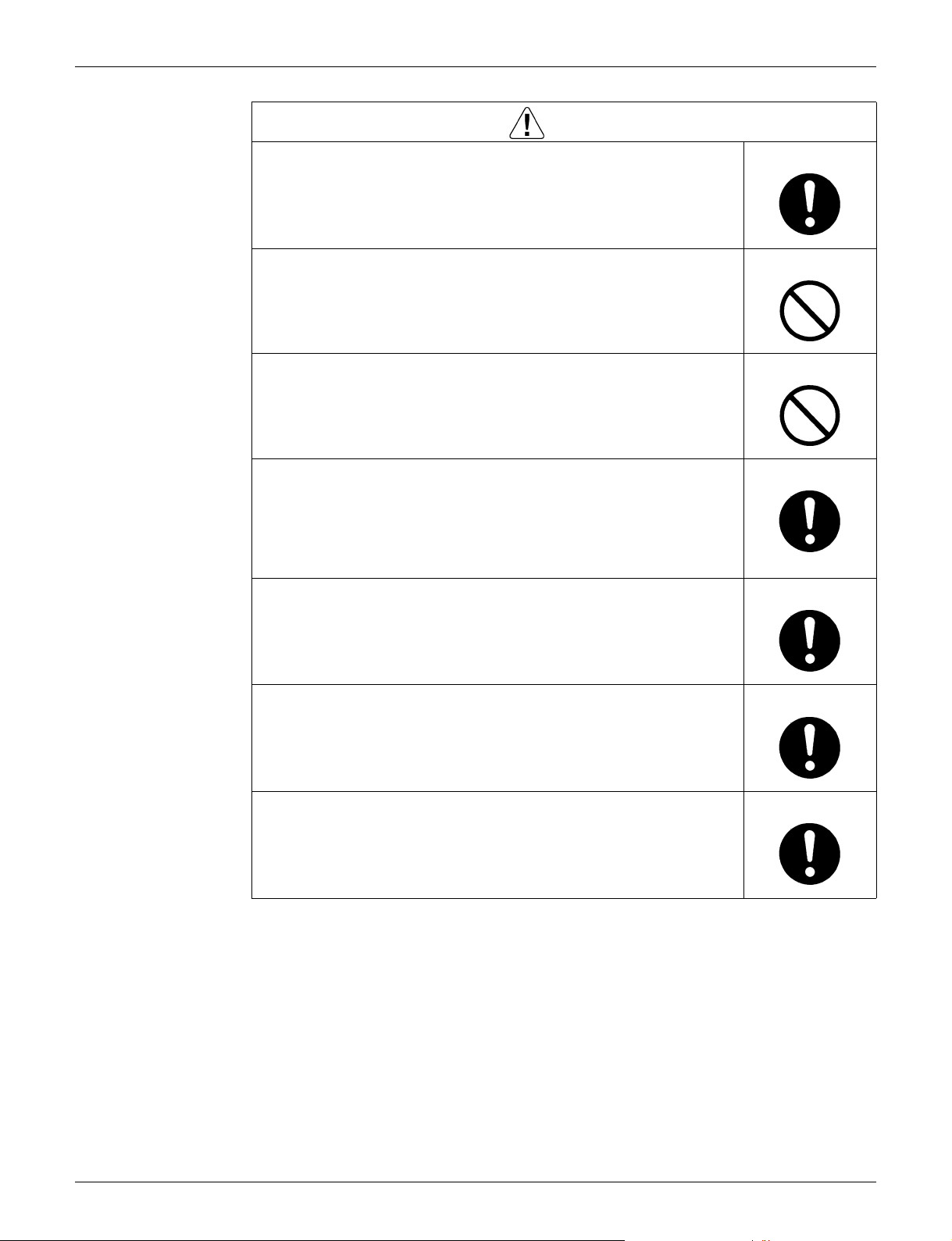
Caution
Be sure to check that the refrigerating cycle section has cooled down
enough before conducting repair work.
Working on the unit when the refrigerating cycle section is hot may cause
burns.
Conduct welding work in a well-ventilated place.
Using a welder in an enclosed room may cause oxygen deficiency.
1.2 Warnings and Cautions Regarding Safety of Users
Warning
Do not store the equipment in a room with fire sources (e.g., naked
flames, gas appliances, electric heaters).
Be sure to use parts listed in the service parts list of the applicable model
and appropriate tools to conduct repair work. Never attempt to modify the
equipment.
The use of inappropriate parts or tools may cause an electrical shock,
excessive heat generation or fire.
If the power cable and lead wires are scratched or have deteriorated, be
sure to replace them.
Damaged cable and wires may cause an electrical shock, excessive heat
generation or fire.
Do not use a joined power cable or extension cable, or share the same
power outlet with other electrical appliances, since it may cause an
electrical shock, excessive heat generation or fire.
Be sure to use an exclusive power circuit for the equipment, and follow
the local technical standards related to the electrical equipment, the
internal wiring regulations, and the instruction manual for installation
when conducting electrical work.
Insufficient power circuit capacity and improper electrical work may cause an
electrical shock or fire.
Be sure to use the specified cable for wiring between the indoor and
outdoor units.
Make the connections securely and route the cable properly so that there is no
force pulling the cable at the connection terminals.
Improper connections may cause excessive heat generation or fire.
vii
SiUS091628EA Safety Cautions
Warning
When wiring between the indoor and outdoor units, make sure that the
terminal cover does not lift off or dismount because of the cable.
If the cover is not mounted properly, the terminal connection section may cause
an electrical shock, excessive heat generation or fire.
Do not damage or modify the power cable.
Damaged or modified power cables may cause an electrical shock or fire.
Placing heavy items on the power cable, or heating or pulling the power cable
may damage it.
Do not mix air or gas other than the specified refrigerant (R-32 / R-410A /
R-22) in the refrigerant system.
If air enters the refrigerant system, an excessively high pressure results,
causing equipment damage and injury.
If the refrigerant gas leaks, be sure to locate the leaking point and repair
it before charging the refrigerant. After charging the refrigerant, make
sure that there is no leak.
If the leaking point cannot be located and the repair work must be stopped, be
sure to pump-down, and close the service valve, to prevent refrigerant gas from
leaking into the room. Refrigerant gas itself is harmless, but it may generate
toxic gases when it contacts flames, such as those from fan type and other
heaters, stoves and ranges.
When relocating the equipment, make sure that the new installation site
has sufficient strength to withstand the weight of the equipment.
If the installation site does not have sufficient strength or the installation work
is not conducted securely, the equipment may fall and cause injury.
Check to make sure that the power cable plug is not dirty or loose, then
insert the plug into a power outlet securely.
If the plug is dusty or has a loose connection, it may cause an electrical shock
or fire.
When replacing the coin battery in the remote controller, be sure to
dispose of the old battery to prevent children from swallowing it.
If a child swallows the coin battery, see a doctor immediately.
viii
Safety Cautions SiUS091628EA
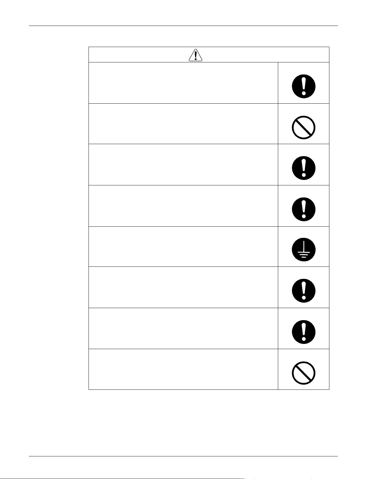
Caution
Installation of a leakage breaker is necessary in some cases depending
on the conditions of the installation site, to prevent electrical shocks.
Do not install the equipment in a place where there is a possibility of
combustible gas leaks.
If combustible gas leaks and remains around the unit, it may cause a fire.
Check to see if parts and wires are mounted and connected properly, and
if connections at the soldered or crimped terminals are secure.
Improper installation and connections may cause excessive heat generation,
fire or an electrical shock.
If the installation platform or frame has corroded, replace it.
A corroded installation platform or frame may cause the unit to fall, resulting in
injury.
Check the earth / grounding, and repair it if the equipment is not properly
earthed / grounded.
Improper earth / grounding may cause an electrical shock.
Be sure to measure insulation resistance after the repair, and make sure
that the resistance is 1 MΩ or higher.
Faulty insulation may cause an electrical shock.
Be sure to check the drainage of the indoor unit after the repair.
Faulty drainage may cause water to enter the room and wet the furniture and
floor.
Do not tilt the unit when removing it.
The water inside the unit may spill and wet the furniture and floor.
ix

SiUS091628EA Icons Used
2. Icons Used
The following icons are used to attract the attention of the reader to specific information.
Icon Type of
Information
Warning A Warning is used when there is danger of personal injury.
Warning
Caution A Caution is used when there is danger that the reader, through
Caution
Note A Note provides information that is not indispensable, but may
Note:
Reference A Reference guides the reader to other places in this binder or
Description
incorrect manipulation, may damage equipment, lose data, get
an unexpected result or have to restart (part of) a procedure.
nevertheless be valuable to the reader, such as tips and tricks.
in this manual, where he/she will find additional information on a
specific topic.
x

SiUS091628EA
Part 1
List of Functions
1. Functions.....................................................................................................2
1 List of Functions
SiUS091628EA Functions
1. Functions
Category Functions
FFQ09/12/15/18Q2VJU
RX09/12/15/18QMVJU
with BYFQ60B3W1
FFQ09/12/15/18Q2VJU
Basic
Functions
Compressor Oval scroll compressor — — Air filter — —
Comfortable
Airflow
Comfort
Control
Operation Automatic operation
Lifestyle
Convenience
Inverter (with inverter power control)
Operation limit for cooling
Operation limit for heating
PAM control — —
Standby electricity saving — — Longlife filter
Swing compressor
Rotary compressor — — Wipe-clean flat panel — —
Reluctance DC motor
Power-airflow flap (horizontal blade) — — MOLD PROOF operation — —
Power-airflow dual flaps
(horizontal blade)
Power-airflow diffuser — — 72-hour ON/OFF TIMER
Wide-angle louvers (vertical blades) — — NIGHT SET mode — —
Auto-swing (up and down)
Auto-swing (right and left) — — Worry Free
Individual flap control —
3-D airflow — — Wiring error check function — —
COMFORT AIRFLOW operation — —
Auto fan speed
Indoor unit quiet operation — — Flexibility
NIGHT QUIET mode (automatic) — —
OUTDOOR UNIT QUIET operation
(manual)
Presence and floor sensor (option) —
Hot-start function
Draft prevention with sensor
Automatic defrosting
Program dry function
Fan only
Setback function
POWERFUL operation (non-inverter) — — Remote
POWERFUL operation (inverter) — —
Priority-room setting — —
COOL/HEAT mode lock — —
HOME LEAVE operation — — DIII-NET compatible (adaptor) (option) — —
ECONO operation — — Remote
Indoor unit ON/OFF button — — Wired (option)
Signal receiving sign
R/C with back light
Note:
: Available
z
zz
Refer to
P. 133
zz
zz
——
zz
z★
z★1z★
——
z★
zz
zz
zz
zz
zz
zz
z★1z★
2
z★
z★
4
★
★
z★1z★
— : Not available
Category Functions
RX09/12/15/18QMVJU
with BYFQ60C2W1W(S)
Health &
Cleanliness
Timer Schedule TIMER operation
(Reliability &
1 Self-diagnosis (R/C, LED)
Durability)
1
1
1
Control
Controller
2
4
1
Auto cleaning filter — —
Air-purifying filter — —
Titanium apatite deodorizing filter
(option)
Filter cleaning indicator
Washable grille
Good-sleep cooling operation — —
Off Timer (power off forget prevention)
Auto-restart (after power failure)
Anti-corrosion treatment of outdoor heat
exchanger
Multi-split/split type compatible indoor
unit
H/P, C/O compatible indoor unit — —
Flexible power supply correspondence — —
Chargeless
Either side drain (right or left) — —
Power selection — —
Low outdoor temperature cooling
operation (-20°C) (-4°F)
°F/°C changeover R/C temperature
display (factory setting: °F)
Remote control adaptor
(normal open pulse contact) (option)
Remote control adaptor
(normal open contact) (option)
Wireless (option)
1: With wired remote controller
★
2: With wireless remote controller
★
3: With air direction adjustment grille (option)
★
4: Receiving sound only
★
FFQ09/12/15/18Q2VJU
RX09/12/15/18QMVJU
with BYFQ60B3W1
FFQ09/12/15/18Q2VJU
——
zz
zz
zz
z★1z★
z★2z★
z★1z★
zz
zz
——
zz
32.8 ft
32.8 ft
(10 m)
(10 m)
z★3z★
z★1z★
——
——
zz
zz
RX09/12/15/18QMVJU
with BYFQ60C2W1W(S)
1
2
1
3
1
List of Functions 2

SiUS091628EA
Part 2
Specifications
1. Specifications ..............................................................................................4
3 Specifications
SiUS091628EA Specifications
1. Specifications
60 Hz, 208 - 230V
Model
Capacity
Rated (Min. ~ Max.)
Running Current (Rated) A 3.64 - 3.29 3.43 - 3.10 4.61 - 4.17 4.96 - 4.49
Power Consumption
Rated
(Min. ~ Max.)
Power Factor (Rated) % 92.5 - 92.5 89.8 - 89.9 90.1 - 90.1 95.5 - 95.4
SEER / HSPF 20.90 11.70 20.20 11.20
COP (Rated) W/W — 4.58 — 4.02
EER (Rated)
Piping Connections
Heat Insulation Both Liquid and Gas Pipes Both Liquid and Gas Pipes
Max. Interunit Piping Length ft (m) 65-5/8 (20) 65-5/8 (20)
Max. Interunit Height Difference ft (m) 49-1/4 (15) 49-1/4 (15)
Chargeless ft (m) 32-13/16 (10) 32-13/16 (10)
Amount of Additional Charge of
Refrigerant
Indoor Unit FFQ09Q2VJU FFQ12Q2VJU
Decoration Panel (1)
Decoration Panel (2)
Airflow Rate
Fan
Running Current (Rated) A 0.23 - 0.21 0.23 - 0.21 0.27 - 0.24 0.27 - 0.24
Power Consumption (Rated) W 23 23 27 27
Power Factor (Rated) % 48.1 - 47.6 48.1 - 47.6 48.1 - 48.9 48.1 - 48.9
Temperature Control Microcomputer Control Microcomputer Control
Dimensions (H × W × D) in. (mm) 10-1/4 × 22-5/8 × 22-5/8 (260 × 575 × 575) 10-1/4 × 22-5/8 × 22-5/8 (260 × 575 × 575)
Packaged Dimensions (H × W × D) in. (mm) 11 × 27 × 23-1/2 (280 × 686 × 597) 11 × 27 × 23-1/2 (280 × 686 × 597)
Weight Lbs (kg) 36 (16) 36 (16)
Gross Weight Lbs (kg) 40 (18) 40 (18)
Sound Pressure Level H / M / L dB(A) 38 / 35 / 29 38 / 35 / 29 39 / 36 / 30 39 / 36 / 30
Outdoor Unit RX09QMVJU RX12QMVJU
Casing Color Ivory White Ivory White
Compressor
Refrigerant Oil
Refrigerant
Airflow Rate H
Fan Type Propeller Propeller
Running Current (Rated) A 3.41 - 3.08 3.20 - 2.89 4.34 - 3.93 4.69 - 4.25
Power Consumption (Rated) W 677 618 837 958
Power Factor (Rated) % 95.4 - 95.6 92.8 - 93.0 92.7 - 92.6 98.2 - 98.0
Starting Current A 7.5 7.5
Dimensions (H × W × D) in. (mm) 21-5/8 × 26-9/16 × 11-3/16 (550 × 675 × 284) 21-5/8 × 26-9/16 × 11-3/16 (550 × 675 × 284)
Packaged Dimensions (H × W × D) in. (mm) 24-3/4 × 32-11/16 × 16 (629 × 830 × 407) 24-3/4 × 32-11/16 × 16 (629 × 830 × 407)
Weight Lbs (kg) 60 (27) 60 (27)
Gross Weight Lbs (kg) 71 (32) 71 (32)
Sound Pressure Level H dB(A) 46 50 49 51
Drawing No. 3D106061A 3D106062
Indoor Unit FFQ09Q2VJU FFQ12Q2VJU
Outdoor Unit
Btu/h 9,100 (4,600 ~ 11,000) 10,000 (4,600 ~ 14,000) 10,800 (4,600 ~ 13,300) 13,500 (4,600 ~ 16,800)
W 700 (280 ~ 1,050) 641 (250 ~ 1,150) 864 (280 ~ 1,410) 985 (250 ~ 1,450)
Liquid in. (mm)
Gas in. (mm)
Drain in. (mm) VP20 (O.D.
Model BYFQ60B3W1 BYFQ60B3W1
Color White White
Dimensions (H × W × D) 2-3/16 × 27-9/16 × 27-9/16 (55 × 700 × 700) 2-3/16 × 27-9/16 × 27-9/16 (55 × 700 × 700)
Weight (Mass) Lbs (kg) 6 (2.7) 6 (2.7)
Model BYFQ60C2W1W / BYFQ60C2W1S BYFQ60C2W1W / BYFQ60C2W1S
Color White / Silver White / Silver
Dimensions (H × W × D) 1-13/16 × 24-7/16 × 24-7/16 (46 × 620 × 620) 1-13/16 × 24-7/16 × 24-7/16 (46 × 620 × 620)
Weight (Mass) Lbs (kg) 6.2 (2.8) 6.2 (2.8)
H
M 339 (9.6) 357 (10.1) 353 (10.0) 371 (10.5)
L 268 (7.6) 282 (8.0) 268 (7.6) 282 (8.0)
Type Turbo Fan Turbo Fan
Speed Steps 3 Steps 3 Steps
Type Hermetically Sealed Swing Type Hermetically Sealed Swing Type
Model 1YC23AUXD 1YC23AUXD
Motor Output W 790 790
Type FVC50K FVC50K
Charge oz (L) 12.68 (0.375) 12.68 (0.375)
Type R-410A R-410A
Charge Lbs (kg) 2.09 (0.95) 2.09 (0.95)
Btu/W·h
oz/ft
(g/m)
cfm
(m³/min)
cfm
(m³/min)
Cooling Heating Cooling Heating
13.00 — 12.50 —
378 (10.7) 399 (11.3) 406 (11.5) 427 (12.1)
985 (27.9) 992 (28.1) 1,104 (31.27) 992 (28.1)
RX09QMVJU RX12QMVJU
1/4 (φ 6.4)
φ
3/8 (φ 9.5)
φ
φ
0.21 (20) 0.21 (20)
26)) VP20 (O.D. φ
(φ
1-1/32
1/4 (φ 6.4)
φ
3/8 (φ 9.5)
φ
1-1/32
(φ
26))
Note:
The data are based on the conditions shown in the table below.
Cooling
Heating
Piping Length 25 ft (7.5 m)
Indoor ; 80.0°FDB (26.7°CDB) / 67.0°FWB (19.4°CWB)
Outdoor ; 95.0°FDB (35°CDB) / 75°FWB (23.9°CWB)
Indoor ; 70.0°FDB (21.1°CDB) / 60.0°FWB (15.6°CWB)
Outdoor ; 47°FDB (8.33°CDB) / 43.0°FWB (6.11°CWB)
Conversion Formulae
kcal/h = kW × 860
Btu/h = kW × 3412
cfm = m³/min × 35.3
Specifications 4
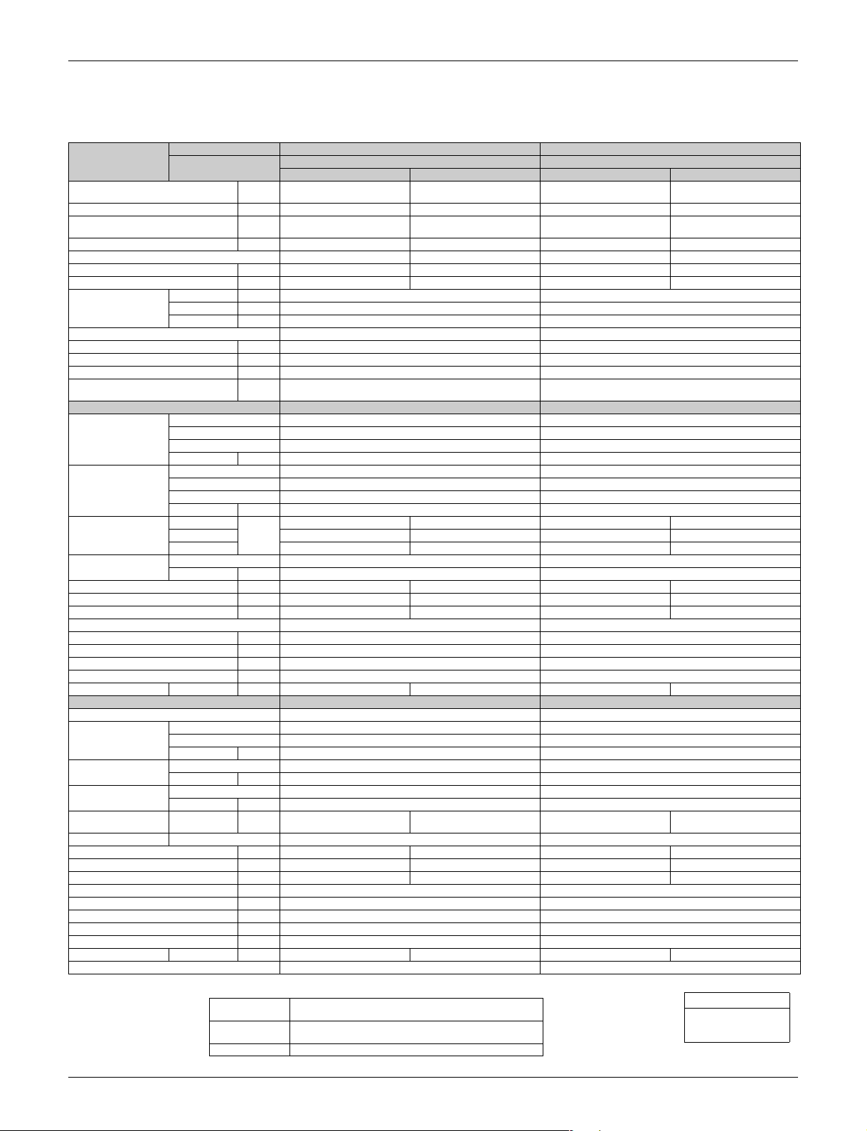
Specifications SiUS091628EA
60 Hz, 208 - 230V
Model
Capacity
Rated (Min. ~ Max.)
Running Current (Rated) A 5.83 - 5.27 6.23 - 5.63 7.12 - 6.44 9.51 - 8.6
Power Consumption
Rated
(Min. ~ Max.)
Power Factor (Rated) % 95.0 - 95.0 95.3 - 95.4 94 - 94 94.8 - 94.8
SEER / HSPF 20.70 11.00 19.30 10.10
COP (Rated) W/W — 3.86 — 3.36
EER (Rated)
Piping Connections
Heat Insulation Both Liquid and Gas Pipes Both Liquid and Gas Pipes
Max. Interunit Piping Length ft (m) 98-7/16 (30) 98-3/8 (30)
Max. Interunit Height Difference ft (m) 65-5/8 (20) 65-5/8 (20)
Chargeless ft (m) 32-13/16 (10) 32-13/16 (10)
Amount of Additional Charge of
Refrigerant
Indoor Unit FFQ15Q2VJU FFQ18Q2VJU
Decoration Panel (1)
Decoration Panel (2)
Airflow Rate
Fan
Running Current (Rated) A 0.29 - 0.26 0.29 - 0.26 0.52 - 0.47 0.52 - 0.47
Power Consumption (Rated) W 28 28 51 - 51 51 - 51
Power Factor (Rated) % 46.4 - 46.8 46.4 - 46.8 47.2 - 47.2 47.2 - 47.2
Temperature Control Microcomputer Control Microcomputer Control
Dimensions (H × W × D) in. (mm) 10-1/4 × 22-5/8 × 22-5/8 (260 × 575 × 575) 10-1/4 × 22-5/8 × 22-5/8 (260 × 575 × 575)
Packaged Dimensions (H × W × D) in. (mm) 11 × 27 × 23-1/2 (280 × 686 × 597) 11 × 27 × 23-1/2 (280 × 686 × 597)
Weight Lbs (kg) 36 (16) 39.0 (17.5)
Gross Weight Lbs (kg) 40 (18) 42.0 (19.0)
Sound Pressure Level H / M / L dB(A) 40 / 37 / 31 40 / 37 / 31 44 / 40 / 32 44 / 40 / 32
Outdoor Unit RX15QMVJU RX18QMVJU
Casing Color Ivory White Ivory White
Compressor
Refrigerant Oil
Refrigerant
Airflow Rate H
Fan Type Propeller Propeller
Running Current (Rated) A 5.54 - 5.01 5.94 - 5.37 6.60 - 5.97 8.99 - 8.13
Power Consumption (Rated) W 1,124 1,207 1,341 ~ 1,341 1,824 ~ 1,824
Power Factor (Rated) % 97.5 - 97.5 97.7 - 97.7 97.7 - 97.7 97.5 - 97.5
Starting Current A 8.0 9.51
Dimensions (H × W × D) in. (mm) 28-15/16 × 34-1/4 × 12-5/8 (735 × 870 × 320) 28-15/16 × 34-1/4 × 12-5/8 (735 × 870 × 320)
Packaged Dimensions (H × W × D) in. (mm) 31-7/8 × 41-9/16 × 18-1/4 (810 × 1,056 × 464) 31-7/8 × 41-9/16 × 18-1/4 (810 × 1,056 × 464)
Weight Lbs (kg) 97 (44) 97 (44)
Gross Weight Lbs (kg) 115 (52) 115 (52)
Sound Pressure Level H dB(A) 50 51 54 55
Drawing No. 3D106063A 3D106064
Indoor Unit FFQ15Q2VJU FFQ18Q2VJU
Outdoor Unit
Btu/h 14,400 (5,100 ~ 16,200) 16,200 (5,200 ~ 16,300) 17,400 (5,100 ~ 18,800) 21,600 (5,400 ~ 21,800)
W 1,152 (310 ~ 1,640) 1,235 (330 ~ 1,300) 1,392 (340 ~ 1,650) 1,875 (370 ~ 1,920)
Liquid in. (mm)
Gas in. (mm)
Drain in. (mm) VP20 (O.D.
Model BYFQ60B3W1 BYFQ60B3W1
Color White White
Dimensions (H × W × D) 2-3/16 × 27-9/16 × 27-9/16 (55 × 700 × 700) 2-3/16 × 27-9/16 × 27-9/16 (55 × 700 × 700)
Weight (Mass) Lbs (kg) 6 (2.7) 6 (2.7)
Model BYFQ60C2W1W / BYFQ60C2W1S BYFQ60C2W1W / BYFQ60C2W1S
Color White / Silver White / Silver
Dimensions (H × W × D) 1-13/16 × 24-7/16 × 24-7/16 (46 × 620 × 620) 1-13/16 × 24-7/16 × 24-7/16 (46 × 620 × 620)
Weight (Mass) Lbs (kg) 6.2 (2.8) 6.2 (2.8)
H
M 367 (10.4) 385 (10.9) 378 (10.7) 420 (11.9)
L 293 (8.3) 307 (8.7) 275 (7.8) 307 (8.7)
Type Turbo Fan Turbo Fan
Speed Steps 3 Steps 3 Steps
Type Hermetically Sealed Swing Type Hermetically Sealed Swing Type
Model 2YC36PXD 2YC36PXD
Motor Output W 1,100 1,100
Type FVC50K FVC50K
Charge oz (L) 22.0 (0.65) 22.0 (0.65)
Type R-410A R-410A
Charge Lbs (kg) 2.49 (1.13) 2.49 (1.13)
Btu/W·h
oz/ft
(g/m)
cfm
(m³/min)
cfm
(m³/min)
Cooling Heating Cooling Heating
12.50 — 12.50 —
420 (11.9) 441 (12.5) 448 (12.7) 498 (14.1)
2,314 (65.53) 1,896 (53.7) 2,461 (69.7) 2,295 (65)
RX15QMVJU RX18QMVJU
1/4 (φ 6.4)
φ
1/2 (φ 12.7)
φ
φ
0.21 (20) 0.21 (20)
26)) VP20 (O.D. φ
(φ
1-1/32
1/4 (φ 6.4)
φ
1/2 (φ 12.7)
φ
1-1/32
(φ
26))
Note:
The data are based on the conditions shown in the table below.
Cooling
Heating
Piping Length 25 ft (7.5 m)
Indoor ; 80.0°FDB (26.7°CDB) / 67.0°FWB (19.4°CWB)
Outdoor ; 95.0°FDB (35°CDB) / 75°FWB (23.9°CWB)
Indoor ; 70.0°FDB (21.1°CDB) / 60.0°FWB (15.6°CWB)
Outdoor ; 47°FDB (8.33°CDB) / 43.0°FWB (6.11°CWB)
Conversion Formulae
kcal/h = kW × 860
Btu/h = kW × 3412
cfm = m³/min × 35.3
5 Specifications

SiUS091628EA
Part 3
Printed Circuit Board
Connector Wiring Diagram
1. Indoor Unit...................................................................................................7
1.1 FFQ09/12/15/18Q2VJU................................................................................ 7
2. Wired Remote Controller.............................................................................8
2.1 BRC1E73 ..................................................................................................... 8
3. Wireless Remote Controller Kit ...................................................................9
3.1 BRC082A41W, BRC082A42W(S) ................................................................ 9
4. Outdoor Unit..............................................................................................10
4.1 RX09/12QMVJU......................................................................................... 10
4.2 RX15/18QMVJU......................................................................................... 11
Printed Circuit Board Connector Wiring Diagram 6
Indoor Unit SiUS091628EA
1. Indoor Unit
1.1 FFQ09/12/15/18Q2VJU
Control PCB
(A1P)
1) X15A Connector for float switch
2) X16A Connector for room temperature thermistor (suction air thermistor)
3) X17A, X18A Connector for indoor heat exchanger thermistor
4) X20A Connector for DC fan motor
5) X24A Connector for transmitter board
(when the wireless remote controller (option) is used)
6) X25A Connector for drain pump motor
7) X27A Connector for terminal block (for inter-unit wiring)
8) X30A Connector for terminal block (for wired remote controller)
9) X33A Connector for adaptor for wiring (option)
10) X35A Connector for wiring adaptor for electrical appendices (option)
11) X36A Connector for swing motors on decoration panel (option)
12) X80A Connector for decoration panel (BYFQ60B3W1) (option)
13) X81A Connector for sensor kit (BRYQ60A2W(S)) (option)
14) HAP LED for service monitor (green)
15) DS1 DIP switch
16) F1U Fuse (5 A, 250 V)
X18A
X16A
X81A
X17A
X30A
X15A
X36A X33A X35A
HAPX25A
X80A
X20ADS1 X24A
F1U
X27A
2P452045-1
7 Printed Circuit Board Connector Wiring Diagram

SiUS091628EA Wired Remote Controller
2. Wired Remote Controller
2.1 BRC1E73
Wired Remote
Controller PCB 1) P1, P2 Terminal for indoor unit
2) R4T Room temperature thermistor
P2
P1
R4T
2P298037-7
Printed Circuit Board Connector Wiring Diagram 8
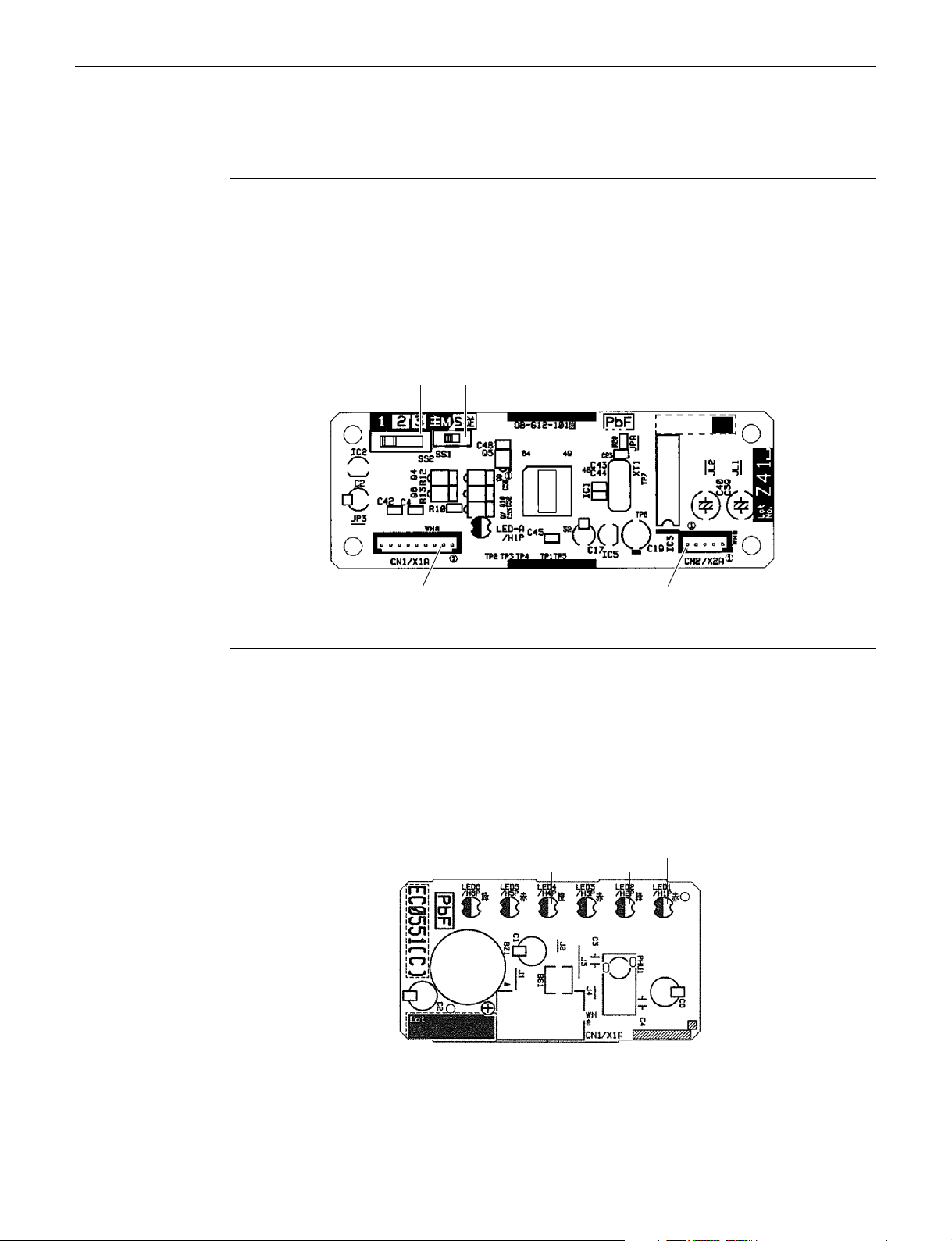
Wireless Remote Controller Kit SiUS091628EA
3. Wireless Remote Controller Kit
3.1 BRC082A41W, BRC082A42W(S)
Transmitter
Board (A2P)
1) X1A Connector for receiver (A3P)
2) X2A Connector for control PCB (A1P)
3) SS1 MAIN/SUB setting switch
Refer to page 123 for details.
∗
4) SS2 Address setting switch
Refer to page 123 for details.
∗
SS1
SS2
Receiver (A3P)
X1A
1) X1A Connector for transmitter board (A2P)
2) BS1 Emergency operation switch
3) LED1 (H1P) LED for operation (red)
4) LED2 (H2P) LED for timer (green)
5) LED3 (H3P) LED for filter cleaning sign (red)
6) LED4 (H4P) LED for defrost operation (orange)
LED 3
LED 4
LED 2
X2A
LED 1
3P156326-3
X1A BS1
LED5 and LED6 do not function.
★
9 Printed Circuit Board Connector Wiring Diagram
3P174795-1
SiUS091628EA Outdoor Unit
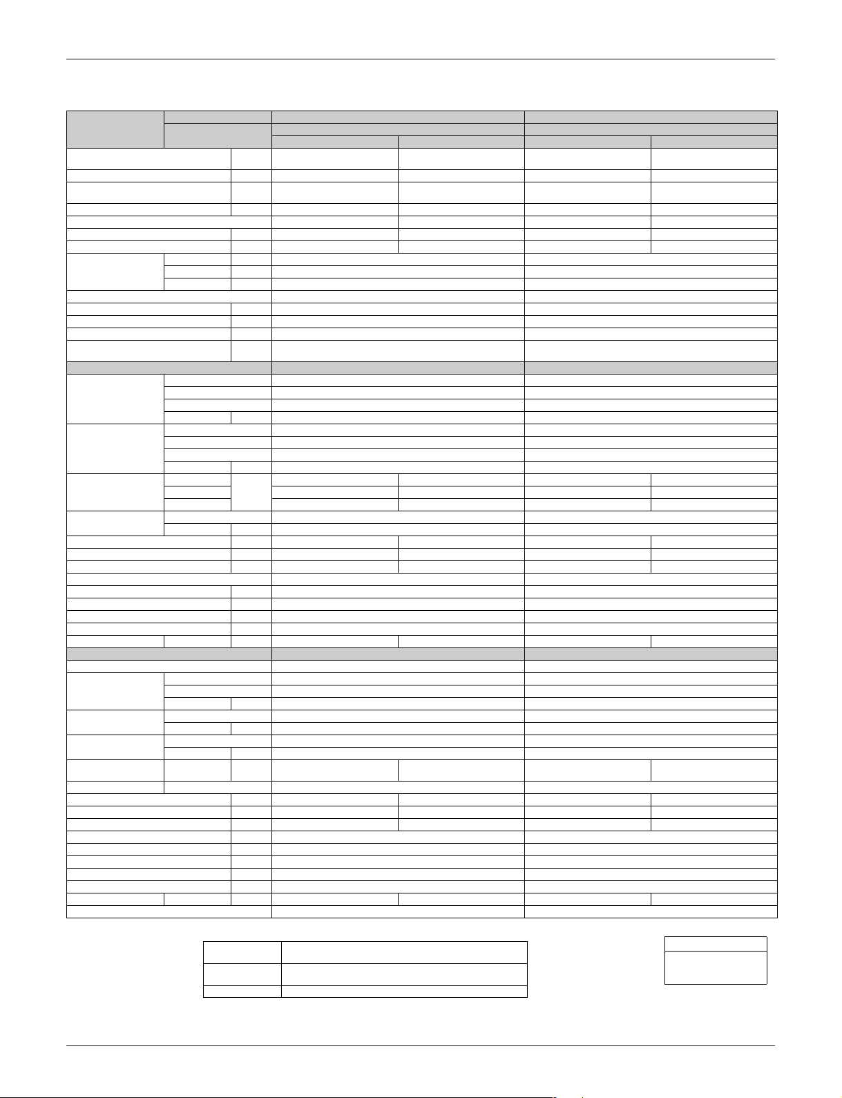
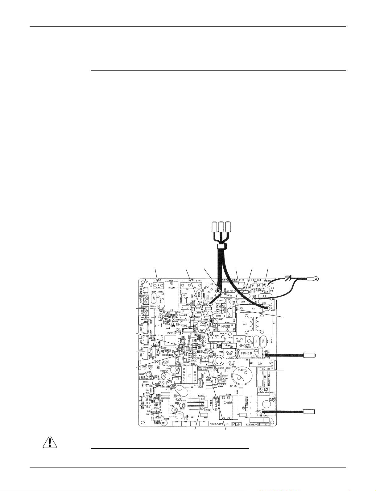
4. Outdoor Unit
4.1 RX09/12QMVJU
Main PCB (PCB1)
1) S20 Connector for electronic expansion valve coil
2) S30 Connector for compressor
3) S40 Connector for overload protector
4) S71 Connector for DC fan motor
5) S80 Connector for four way valve coil
6) S90 Connector for thermistors
(outdoor temperature, outdoor heat exchanger, discharge pipe)
7) HL1, HN1, S Connector for terminal block
8) E1, E2 Terminal for ground wire
9) HR1, HR2 Connector for reactor
10)FU1, FU2 Fuse (3.15 A, 250 V)
11)FU3 Fuse (20 A, 250 V)
12)J6 Jumper for facility setting
Refer to page 125 for details.
∗
12)LED A LED for service monitor (green)
13)V2, V3, V150 Varistor
S20
LED A
S90
J6
S80 S71
HL1, HN1, S
V150
FU3
V2
V3
E1, E2
FU1
HR1
FU2
HR2
S30
S40
2P415459-46
Caution Replace the PCB if you accidentally cut a wrong jumper.
Jumpers are necessary for electronic circuit. Improper operation may occur if you cut any of them.
Printed Circuit Board Connector Wiring Diagram 10

Outdoor Unit SiUS091628EA
4.2 RX15/18QMVJU
Main PCB
1) S20 Connector for electronic expansion valve coil
2) S40 Connector for overload protector
3) S70 Connector for DC fan motor
4) S80 Connector for four way valve coil
5) S90 Connector for thermistors
(outdoor temperature, outdoor heat exchanger, discharge pipe)
6) HL1, HN1, S Connector for terminal block
7) E1, E2 Terminal for ground
8) U, V, W Connector for compressor
9) FU1, FU2 Fuse (3.15 A, 250 V)
10)FU3 Fuse (30 A, 250 V)
11)J6 Jumper for facility setting
Refer to page 125 for details.
∗
12)LED A LED for service monitor (green)
13)V1, V2, V3 Varistor
V2
FU1
V1
E1, E2
V3
HL1, HN1, S
FU3
S80 S20 S40 S90 J6
LED A
U, V, W
FU2
S70
2P443814-20
Caution Replace the PCB if you accidentally cut a wrong jumper.
Jumpers are necessary for electronic circuit. Improper operation may occur if you cut any of them.
11 Printed Circuit Board Connector Wiring Diagram

SiUS091628EA
Part 4
Functions and Control
1. Main Functions..........................................................................................13
1.1 Temperature Control .................................................................................. 13
1.2 Frequency Principle.................................................................................... 13
1.3 Airflow Direction Control............................................................................. 15
1.4 Fan Speed Control for Indoor Unit ............................................................. 15
1.5 Program Dry Operation .............................................................................. 16
1.6 Clock and Calendar Setting
(With Wired Remote Controller BRC1E73) ................................................ 17
1.7 Schedule TIMER Operation
(With Wired Remote Controller BRC1E73) ................................................ 19
1.8 Setback Function
(With Wired Remote Controller BRC1E73) ................................................ 23
1.9 Drain Pump Control .................................................................................... 23
1.10 Hot Start Control (In Heating Operation Only)............................................ 25
1.11 Presence and Floor Sensors (Option) ........................................................ 26
1.12 Other Functions.......................................................................................... 29
2. Control Specification .................................................................................30
2.1 Mode Hierarchy .......................................................................................... 30
2.2 Frequency Control ...................................................................................... 31
2.3 Controls at Mode Changing/Start-up.......................................................... 33
2.4 Discharge Pipe Temperature Control......................................................... 35
2.5 Input Current Control .................................................................................. 36
2.6 Freeze-up Protection Control ..................................................................... 37
2.7 Heating Peak-cut Control ........................................................................... 37
2.8 Outdoor Fan Control................................................................................... 38
2.9 Liquid Compression Protection Function.................................................... 38
2.10 Defrost Control ........................................................................................... 39
2.11 Electronic Expansion Valve Control ........................................................... 40
2.12 Malfunctions ............................................................................................... 43
Functions and Control 12
Main Functions SiUS091628EA
1. Main Functions
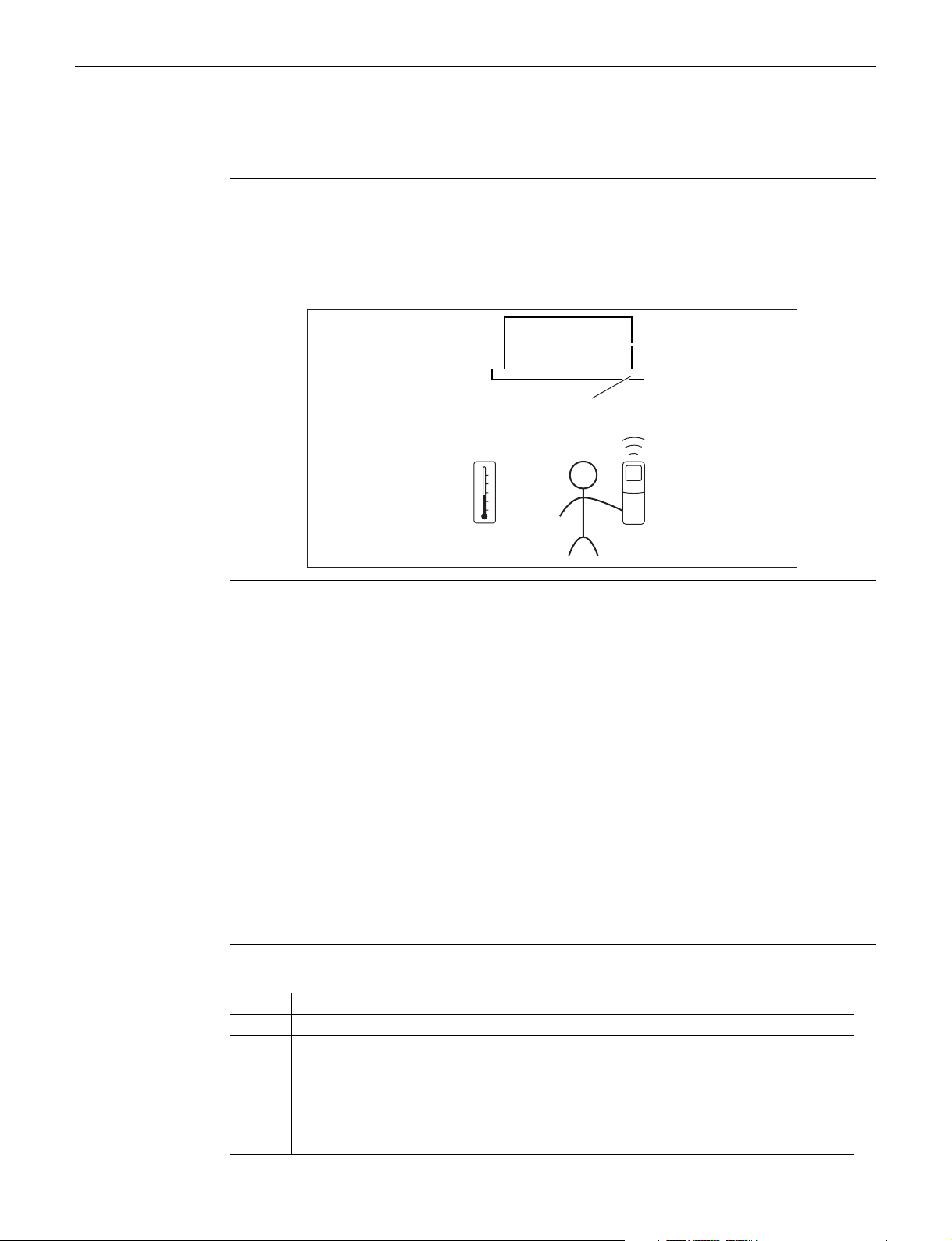
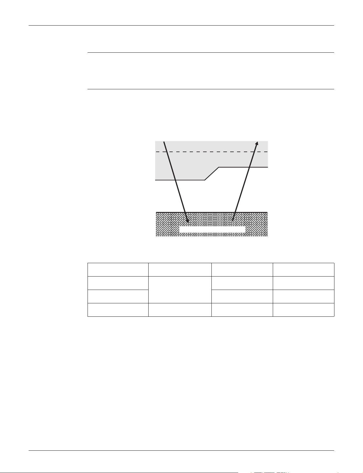
1.1 Temperature Control
Definitions of
Temperatures
Temperature
Control
The definitions of temperatures are classified as following.
Room temperature: temperature of lower part of the room
Set temperature: temperature set by remote controller
Room thermistor temperature: temperature detected by room temperature thermistor
Target temperature: temperature determined by microcomputer
Target temperature
Room thermistor temperature
Set temperature
Room temperature
(R24366)
The temperature of the room is detected by the room temperature thermistor. However, there is a
difference between the temperature detected by room temperature thermistor and the temperature
of lower part of the room, depending on the installation condition. Practically, the temperature
control is done by the target temperature appropriately adjusted for the indoor unit and the
temperature detected by room temperature thermistor.
1.2 Frequency Principle
Control
Parameters
Inverter Principle To regulate the capacity, a frequency control is needed. The inverter makes it possible to control
The frequency of the compressor is controlled by the following 2 parameters:
The load condition of the operating indoor unit
The difference between the room thermistor temperature and the target temperature
The target frequency is adapted by additional parameters in the following cases:
Frequency restrictions
Initial settings
Forced cooling operation
the rotation speed of the compressor. The following table explains the inverter principle:
Phase Description
1 The supplied AC power source is converted into the DC power source for the present.
2 The DC power source is reconverted into the three phase AC power source with variable
frequency.
When the frequency increases, the rotation speed of the compressor increases resulting
in an increase of refrigerant circulation. This leads to a larger amount of heat exchange
per unit.
When the frequency decreases, the rotation speed of the compressor decreases
resulting in a decrease of refrigerant circulation. This leads to a smaller amount of heat
exchange per unit.
13 Functions and Control
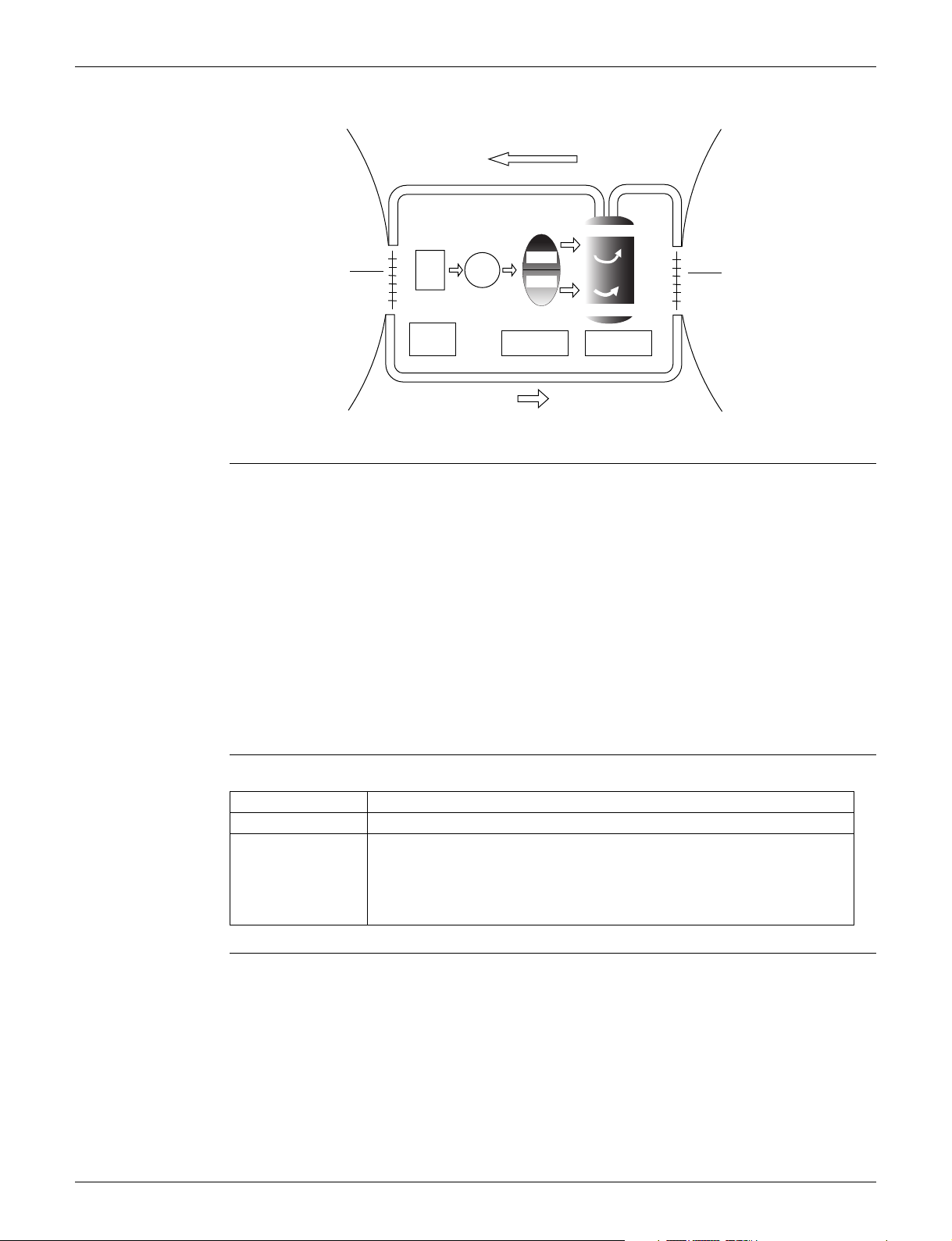
SiUS091628EA Main Functions
The following drawing shows a schematic view of the inverter principle:
Refrigerant circulation rate (high)
Amount of heat
exchanged air (large)
Amount of heat
exchanged air (small)
AC
freq=
constant
DC
power
power
50 Hz
freq=variable
60 Hz
Refrigerant circulation rate (low)
Inverter Features The inverter provides the following features:
The regulating capacity can be changed according to the changes in the outdoor temperature
and cooling/heating load.
Quick heating and quick cooling
The rotation speed of the compressor is increased when starting the heating (or cooling). This
enables to reach the set temperature quickly.
Even during extreme cold weather, high capacity is achieved. It is maintained even when the
outdoor temperature is 2°C (35.6 °F).
Comfortable air conditioning
A fine adjustment is integrated to keep the room temperature constant.
Energy saving heating and cooling
Once the set temperature is reached, the energy saving operation enables to maintain the room
temperature at low power.
high f
low f
high speed
low speed
capacity=
variable
Amount of heat
exchanged air (large)
Amount of heat
exchanged air (small)
(R2812)
Frequency Limits The following functions regulate the minimum and maximum frequency:
Frequency Functions
Low Four way valve operation compensation. Refer to page 34.
High Compressor protection function. Refer to page 34.
Discharge pipe temperature control. Refer to page 35.
Input current control. Refer to page 36.
Freeze-up protection control. Refer to page 37.
Heating peak-cut control. Refer to page 37.
Defrost control. Refer to page 39.
Forced Cooling
Refer to page 114 for details.
Operation
Functions and Control 14
Main Functions SiUS091628EA
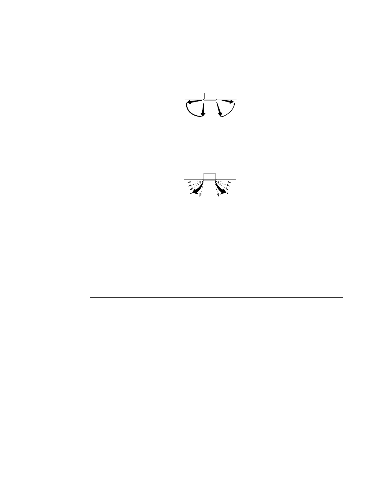
1.3 Airflow Direction Control
Outline There are two types of airflow direction settings.
Automatic swing setting
The flaps automatically oscillate up and down.
Indoor unit
(Automatic swing) (Automatic swing)
(R24069)
Airflow direction fixed setting
You can select from one of the fixed directions.
The display of the remote controller and the actual angle of the flap do not match.
Indoor unit
(Desired position) (Desired position)
(R24070)
Flaps Movement Under the operating conditions shown below, airflow direction is controlled automatically. Actual
operation may be different from what is displayed on the remote controller.
Room temperature is higher than the remote controller’s set temperature in heating operation.
When defrosting in heating operation. The airflow discharges horizontally to avoid blowing cold
air directly on the room occupants.
Under continuous operation with the airflow discharging horizontally.
Individual Flap
Control
With decoration panels BYFQ60C2W1W(S) and wired remote controller (BRC1E73), you can
control each one of the four flaps individually. The following marks are beside each air outlet:
, ,
.
1.4 Fan Speed Control for Indoor Unit
With Wired Remote Controller (BRC1E73)
To change the fan speed, press Fan Speed button and select the fan speed from
Low/Medium/High/Auto for three-speed.
The system may change the fan speed automatically for equipment protection purposes.
The system may turn off the fan when the room temperature is satisfied.
It is normal for a delay to occur when changing the fan speed.
If the Auto is selected for the fan speed, the fan speed varies automatically based on the
difference between set temperature and room temperature.
,
With Wireless Remote Controller Kit (BRC082A41W, BRC082A42W(S))
Press FAN button to select the fan speed, LOW, MEDIUM or HIGH.
15 Functions and Control
SiUS091628EA Main Functions
1.5 Program Dry Operation
Outline Program dry operation removes humidity while preventing the room temperature from lowering.
Since the microcomputer controls both the temperature and airflow rate, the temperature
adjustment and FAN setting buttons are inoperable.
Details The microcomputer automatically sets the temperature and airflow rate. The difference between
the room thermistor temperature at start-up and the target temperature is divided into two zones.
Then, the unit operates in an appropriate capacity for each zone to maintain the temperature and
humidity at a comfortable level.
Room temperature Room temperature
Target temperature X
Zone C = Thermostat ON
X – 1.0°C (1.8°F)
Z = X – 1.0°C (1.8°F)
Y = X – 2.5°C (4.5°F)
or
Y = X – 2.0°C (3.6°F)
Room thermistor
temperature at start-up
24.5°C or more
(76.1°F or more)
16.5 ~ 24°C
(61.7 ~ 75.2°F)
16°C or less
(60.8°F or less)
Zone B
Zone A = Thermostat OFF
Target temperature
X
Room thermistor
temperature at start-up
16°C
(60.8°F)
(R24367)
Thermostat OFF pointYThermostat ON point
X - 2.5°C
(X - 4.5°F)
X - 2.0°C
(X - 3.6°F)
X - 2.0°C
(X - 3.6°F)
X - 1.0°C = 15°C
(X - 1.8°F = 59°F)
Z
X - 1.0°C
(X - 1.8°F)
X - 1.0°C
(X - 1.8°F)
Functions and Control 16
Main Functions SiUS091628EA
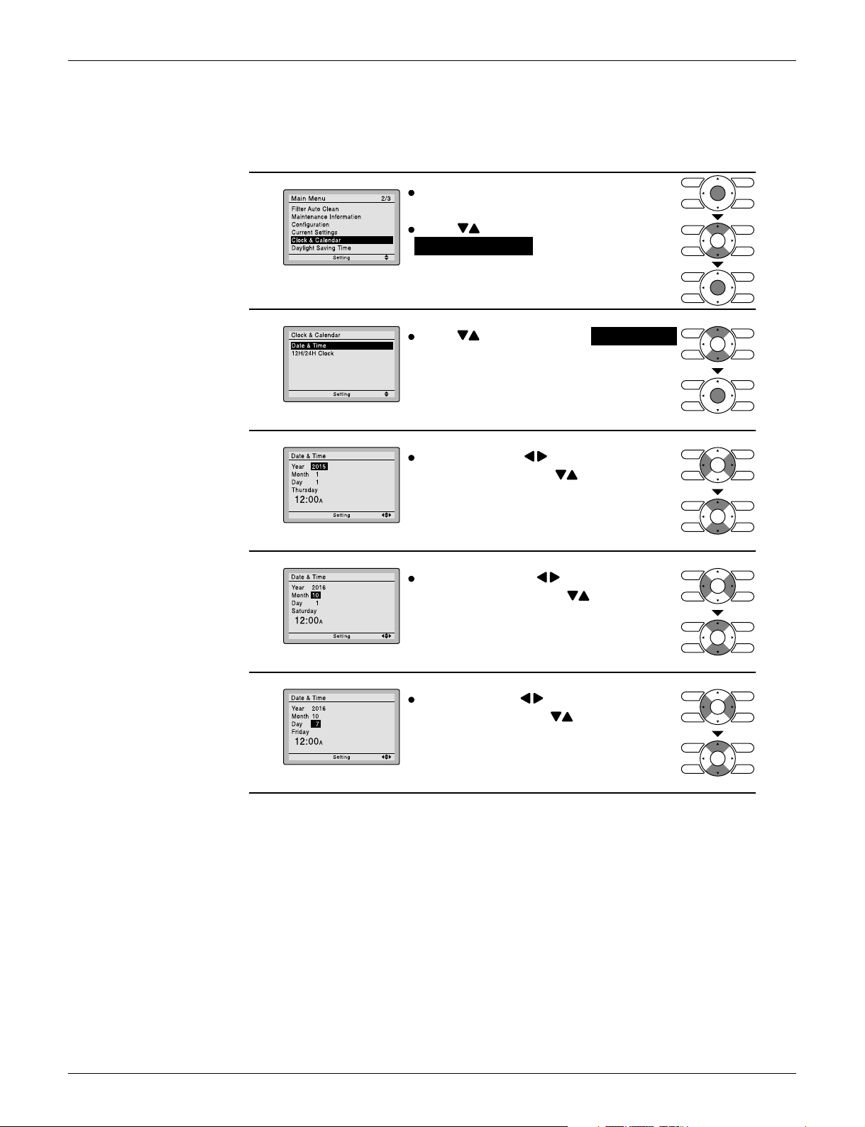
1.6 Clock and Calendar Setting (With Wired Remote Controller
BRC1E73)
1
2
3
4
Press Menu/OK button to
display the main menu screen.
Press buttons to select
Clock & Calendar on the main menu
screen.
Press Menu/OK button to display the
clock & calendar screen.
Press buttons to select Date & Time
on the clock & calendar screen.
Press Menu/OK button to display the
date & time screen.
Select Year with buttons.
Change the year with buttons.
Holding down the button causes the
number to change continuously.
Select Month with buttons.
Change the month with buttons.
Holding down the button causes the
number to change continuously.
Select Day with buttons.
5
17 Functions and Control
Change the day with buttons.
Holding down the button causes the
number to change continuously.
Days of the week change automatically.
(R24368)
SiUS091628EA Main Functions
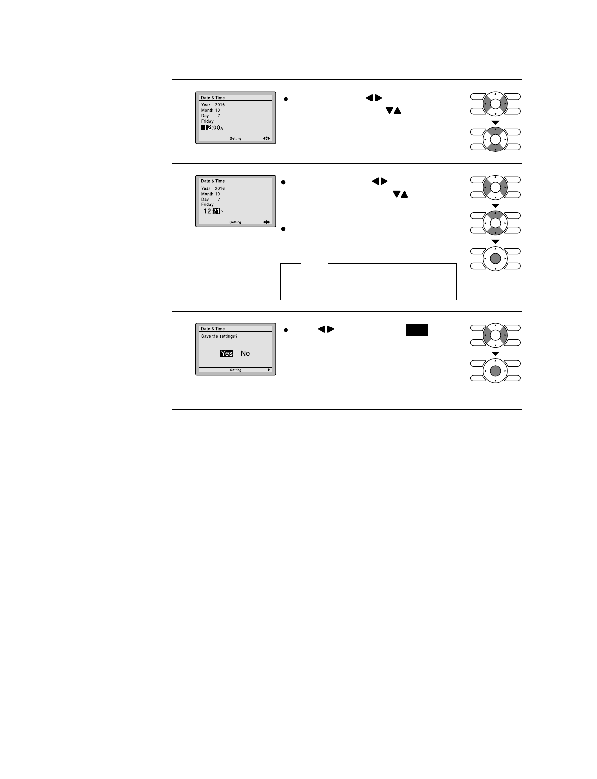
Select Hour with buttons.
6
7
Change the hour with buttons.
Holding down the button causes the
number to change continuously.
Select Minute with buttons.
Change the minute with buttons.
Holding down the button causes the
number to change continuously.
Press Menu/OK button.
The confirmation screen will appear.
Note:
The date can be set between
January 1, 2015 and December 31, 2099.
8
Press button to select Yes on the
confirmation screen.
Press Menu/OK button to confirm the
clock and return to the basic screen.
* When setting the schedule, the display returns to
the settings screen.
(R24072)
Functions and Control 18
Main Functions SiUS091628EA
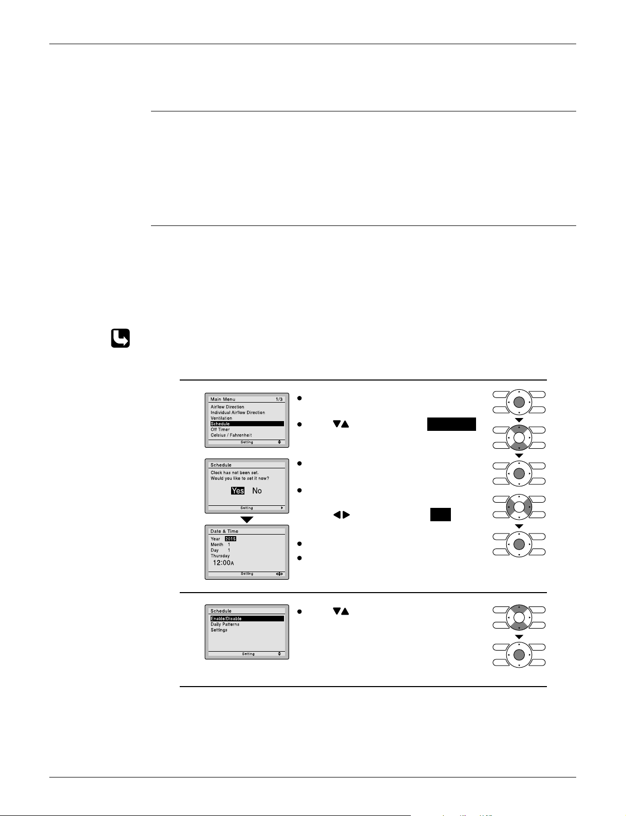
1.7 Schedule TIMER Operation (With Wired Remote Controller
BRC1E73)
Outline Day settings are selected from 4 patterns:
7Days
Weekday/Sat/Sun
Weekday/Weekend
Everyday
Up to 5 actions can be set for each day.
Details Set the startup time and operation stop time.
ON: Startup time, cooling and heating temperature setpoints can be configured.
OFF: Operation stop time, cooling and heating setback temperature setpoints can be
configured.
( --: Indicates that the setback function is disabled for this time period. )
__: Indicates that the temperature setpoint and setback temperature setpoint for this time
period is not specified. The last active setpoint will be utilized.
Refer to Setback function on page 23 for details of setback function.
Setting the schedule
Press Menu/OK button to
1
2
display the main menu screen.
Press buttons to select Schedule .
Press Menu/OK button to display the
schedule screen.
Before setting the schedule, the clock
must be set.
If the clock has not been set, a screen
like the one on the left will appear.
Press buttons to select Yes and
press Menu/OK button.
The date & time screen will appear.
Set the current year, month, day, and
time.
Press buttons to select the desired
function on the schedule screen and
press Menu/OK button.
(R24369)
19 Functions and Control
 Loading...