

Daikin RWEYQ252PCYD, RWEYQ144PCYD, RWEYQ216PCYD, RWEYQ72PCTJ, RWEYQ84PCTJ Installation Manual
...
INSTALLATION MANUAL
System air conditioner
MODEL
RWEYQ72PCYD
RWEYQ84PCYD
RWEYQ144PCYD
RWEYQ168PCYD
RWEYQ216PCYD
RWEYQ252PCYD
Read these instructions carefully before installation.
Keep this manual in a handy place for future reference.
This manual should be left with the equipment owner.
Lire soigneusement ces instructions avant I’installation.
Concerver ce manuel à portée de main pour référence ultérieure.
Ce manuel doit être donné au propriétaire de l’équipement.
RWEYQ72PCTJ
RWEYQ84PCTJ
RWEYQ144PCTJ
RWEYQ168PCTJ
RWEYQ216PCTJ
RWEYQ252PCTJ
English
Français
Español
Lea cuidadosamente estas instrucciones antes de instalar.
Guarde este manual en un lugar a mano para leer en caso de tener alguna duda.
Este manual debe permanecer con el propietario del equipo.
1
2
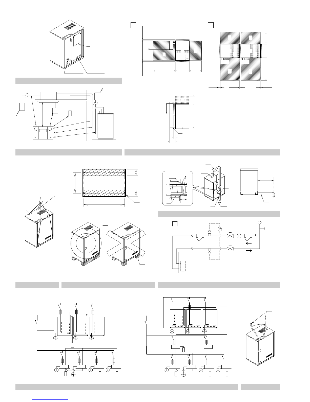
figure 1
2
figure 3
1
≥13/16 (20)
1
(350)
≤13-3/4
[3]
30-11/16 (780)
2 (PCYD)
2 (PCTJ)
≥13/16 (20)
1
2
A
B
5
3
BB
4
A
A
A
A: ≥60 in. (1500 mm)
B: ≥40 in. (1000 mm)
[4]
6
≥35-7/16
(900)
≥13-3/4
≤9-13/16
(250)
(350)
8
≥15-3/8
(390)
21-5/8
≥3-15/16 (100)
(550)
9
5
8
9
≥19-11/16
(500)
(300)
≥11-13/16
39-3/8 (1000)
75
≥13/16
(20)
7 7
5 5
9
8
6 6
≥13/16
(20)
∗10
8
Unit: in. (mm)
9
≥35-7/16 (900) ≥19-11/16 (500)
≥13/16
(20)
figure 2
3
1
4
2
(100)
3-15/16
2
15-3/4 (400)
29-5/16 (744)
3
(100)
3-15/16
12
13
7
14
6
8
2-3/8
(60)
5
11
9
10
[1]
≤15-3/4
(400)
15
Unit: in. (mm)
figure 6
2
4
Unit: in. (mm)
figure 4 figure 5 figure 7
[Heat recovery system][Heat pump system]
3
3
1
2
4
6
1
2
9
3
4
8
3
4
5
1
2
4
3
5
7
6
8
9
10
11
4
6
7
9
2
1
3
8
5
figure 8
figure 9
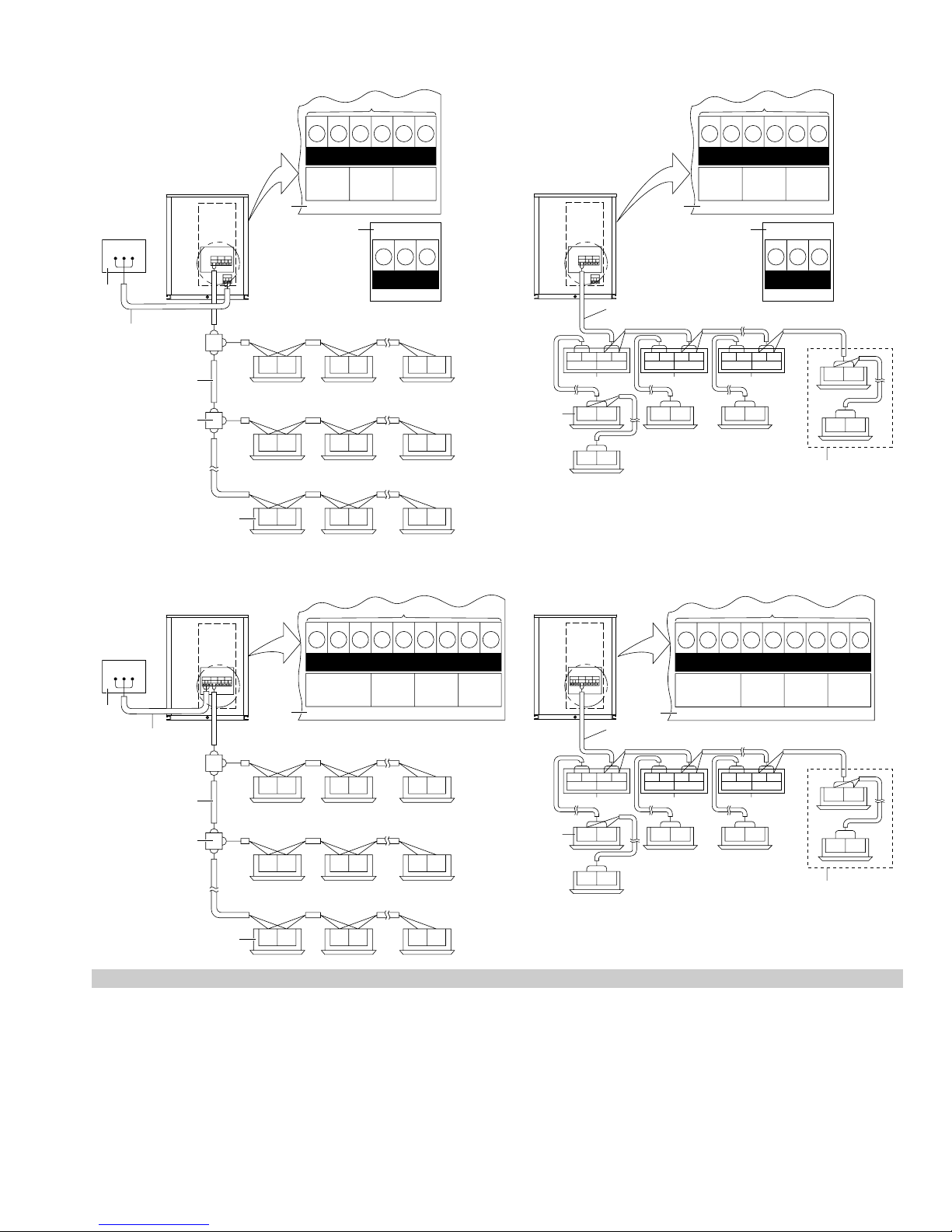
<RWEYQ-PCYD>
7
[Heat recovery system][Heat pump system]
7
A B C
1
3
<RWEYQ-PCTJ>
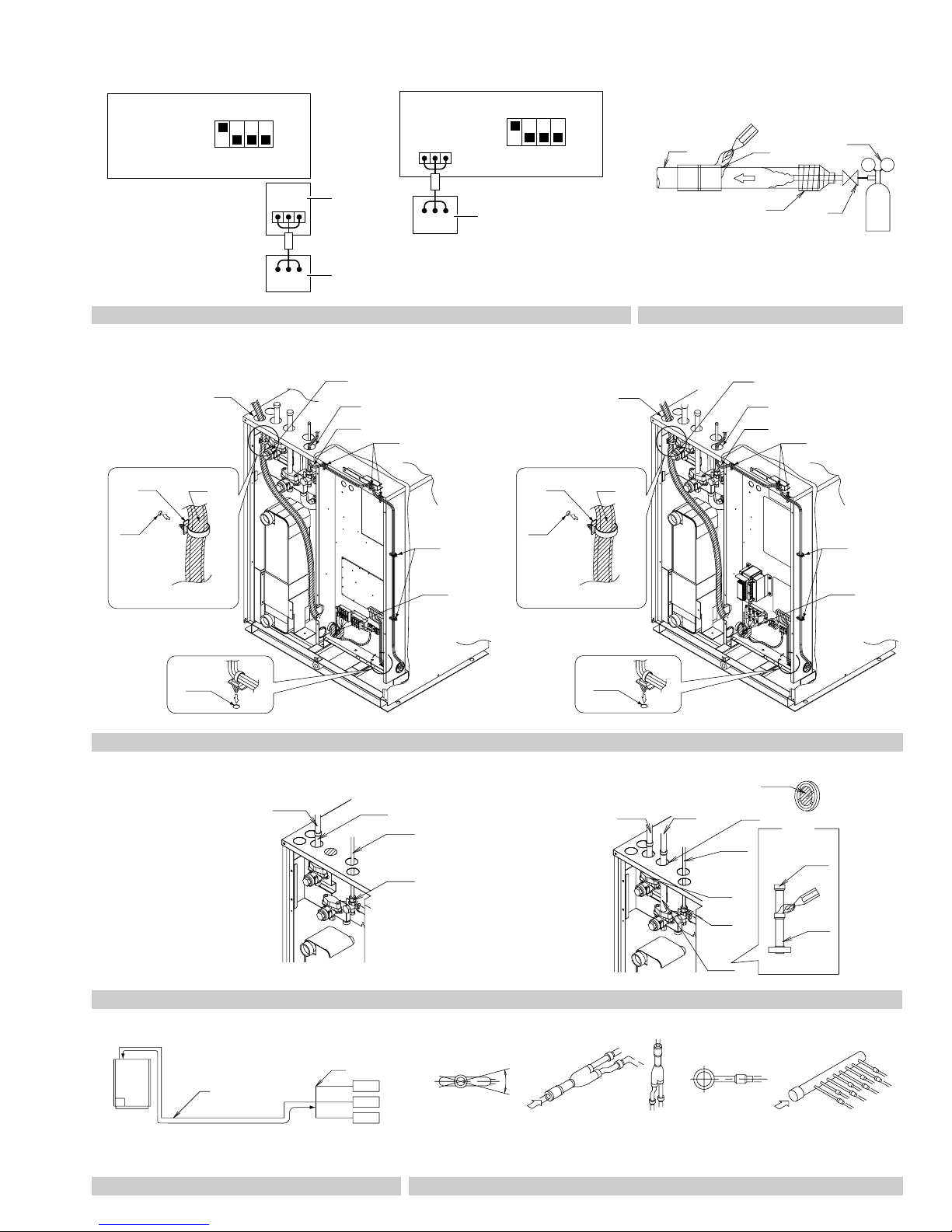
F1 F1F2 F2 Q1 Q2
TO IN/D UNIT
TO OUT/D UNIT TO MULTI UNIT
2
12
A1P
F1F2 F1F2 Q1Q2
ABC ABC
F1 F2 F1 F2 F1 F2
A5P
ABC
C/H SELECTOR
4
5
F1 F2 F1 F2 F1 F2
F1 F2 F1 F2 F1 F2
6
7
[Heat recovery system][Heat pump system]
F1 F1F2 F2
IN/D OUT/D.BS
6
A1P
F1F2 F1F2 Q1Q2
F1 F2
F1 F2
F1 F1F2 F2 Q1 Q2
TO IN/D UNIT
TO OUT/D UNIT TO MULTI UNIT
2
12
A5P
ABC
4
C/H SELECTOR
F1 F1F2 F2
IN/D OUT/D.BS
8
9
F1 F2
F1 F1F2 F2
IN/D OUT/D.BS
10
F1 F2
F1 F2
F1 F2
11
7
A B C
1
figure 10
A1P
ABCF1F2F1F2Q1Q2
A B C F1 F1F2 F2 Q1 Q2
C/H SELECTOR
TO IN/D UNIT
TO OUT/D UNIT TO MULTI UNIT
A1P
ABCF1F2F1F2Q1Q2
2
3
4
F1 F2 F1 F2 F1 F2
5
6
4
F1 F1F2 F2
IN/D OUT/D.BS
8
F1 F2
ABCF1 F1F2 F2 Q1 Q2
C/H SELECTOR
TO IN/D UNIT
2
F1 F1F2 F2
IN/D OUT/D.BS
9
F1 F2
F1 F1F2 F2
IN/D OUT/D.BS
10
F1 F2
TO OUT/D UNIT TO MULTI UNIT
F1 F2
F1 F2
F1 F2 F1 F2 F1 F2
F1 F2 F1 F2 F1 F2
6
F1 F2
11
<RWEYQ-PCYD>
1
A1P
4
F1 F2 F1 F2 Q1 Q2 Q1 Q2 Q1 Q2
8
23
56 6 6
A5P
A BC
9
7
<RWEYQ-PCYD>
1 4
X2M
12
A1P
2
X1M
F1 F2 F1 F2 Q1 Q2
5
A5P
X3M
ABC
43
3
3
<RWEYQ-PCTJ>
1
23
A1P
4
A B C F1 F2 F1 F2 Q1 Q2 Q1 Q2 Q1 Q2
7
56 6 6
9
8
1 23
4
LOW NOISE
TO OUT/D UNIT TO OUT/D UNIT TO OUT/D UNIT
F1 F2
F1
F2
F1 F2 F1 F2
6
5
7
<RWEYQ-PCTJ>
A1P
A B C F1 F2 F1 F2 Q1 Q2
1
12
X1M
X2M
2
X3M
43
3
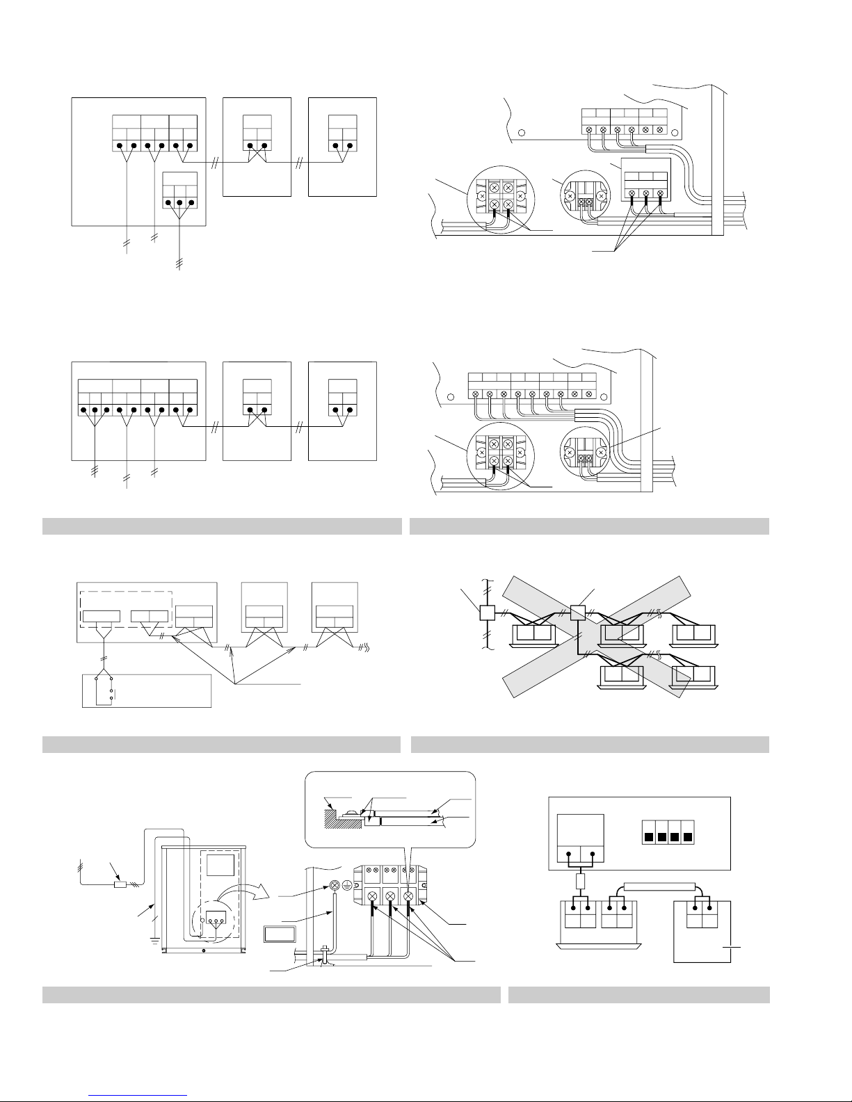
figure 12figure 11
12
F1 F2 F1 F2
F1 F2
4
F1 F2
F1 F2
figure 13
1
2
6
3
8
9
7
figure 15
10
11
12
figure 14
13
14
5
ON
OFF
O
U
T
1
I
N
DS1
234
P1 P2
1
A1P
TO IN/D
UNIT
F1 F2
F1 F2 P1 P2
4
figure 16
<RWEYQ-PCYD>
A1P
ON
OFF
O
U
T
1234
I
N
DS1
A5P
A B C
<RWEYQ-PCTJ>
O
ON
OFF
1
U
T
1234
I
N
DS1
12
3
4
5
6
3
A1P
A B C
2
A B C
figure 17
<RWEYQ-PCTJ>
5
3
A B C
1
figure 18
<RWEYQ-PCYD>
<RWEYQ-PCTJ>
2
2
1
4
6
7
8
9
5
5
3
10
11
3
1
1
4
4
6
6
2
7
7
8
8
9
9
10
10
11
11
figure 19
figure 20
1
figure 21
[Heat pump system]
2
3
[Heat recovery system]
1
2
3
4
78 9
10
[13]
4
14
5
11
5
15
16
∗6
12
∗17
4
1
2
A
3
B
5
[A-arrow view] [B-arrow view]
figure 22
(Fig. A) (Fig. B) (Fig. C)
C
figure 23
1
≤ ±15˚
2
[C-arrow view] [D-arrow view]
[Heat pump system]
1
2
[Heat recovery system]
R410A
1
5
D
3
3
4
11
10 10
12
9
7
3
4
15
5
6
16
18
14
figure 24
5
figure 25
13
1
9
10 10
12
R410A
7
3
2
4
8
15
17
5
4
3
2
[Heat pump system] [Heat recovery system]
1
2
5
3
6
4
1
figure 26 figure 27
6
18
1
2
1
2
4
3
4
3
RWEYQ72PCYD
RWEYQ84PCYD
RWEYQ144PCYD
RWEYQ168PCYD
RWEYQ216PCYD
RWEYQ252PCYD
RWEYQ72 PCTJ
RWEYQ84 PCTJ
RWEYQ14 4PCTJ
RWEYQ168PCTJ
RWEYQ216PCTJ
RWEYQ252PCTJ
VRV-WIV System
air conditioner
Installation
manual
CONTENTS
1. SAFETY CONSIDERATIONS ...................................................... 1
2. INTRODUCTION.......................................................................... 3
2-1 Combination......................................................................... 3
2-2 Standard operation limit ....................................................... 3
2-3 Standard supplied accessories ............................................ 3
2-4 Option accessories............................................................... 3
2-5 Technical specifications ....................................................... 4
2-6 Electrical specifications ........................................................ 4
3. SELECTION OF LOCATION........................................................ 5
4. INSPECTING AND HANDLING THE UNIT.................................. 6
5. UNPACKING AND PLACING THE UNIT ..................................... 6
6. WATER PIPING WORK............................................................... 6
7. HANDLING OF THE BRAZED PLATE-TYPE HEAT
EXCHANGER............................................................................... 7
7-1 When designing the equipment............................................ 7
7-2 Before starting a test run...................................................... 7
7-3 Daily service and maintenance ............................................ 7
7-4 Water quality ........................................................................ 7
7-5 Maintenance of plate-type heat exchanger .......................... 8
8. FIELD WIRING............................................................................. 8
8-1 Optional parts....................................................................... 8
8-2 Power supply circuit and wire requirements......................... 8
8-3 General ................................................................................ 9
8-4 Examples ............................................................................. 9
8-5 In case of a local setting..................................................... 11
9. REFRIGERANT PIPING ............................................................ 11
9-1 Selection of piping material ................................................ 11
9-2 Protection against contamination when installing pipes..... 12
9-3 Pipe connection.................................................................. 12
9-4 Connecting the refrigerant piping ....................................... 12
9-5 Example of connection....................................................... 14
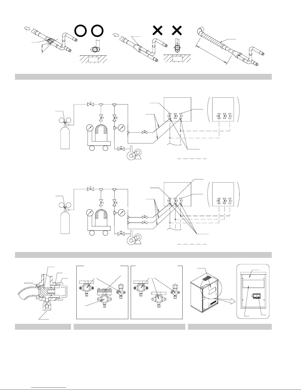
9-6 Air tight test and vacuum drying......................................... 15
9-7 Pipe insulation.................................................................... 15
9-8 Checking of device and installation conditions................... 15
9-9 Additional refrigerant charge .............................................. 15
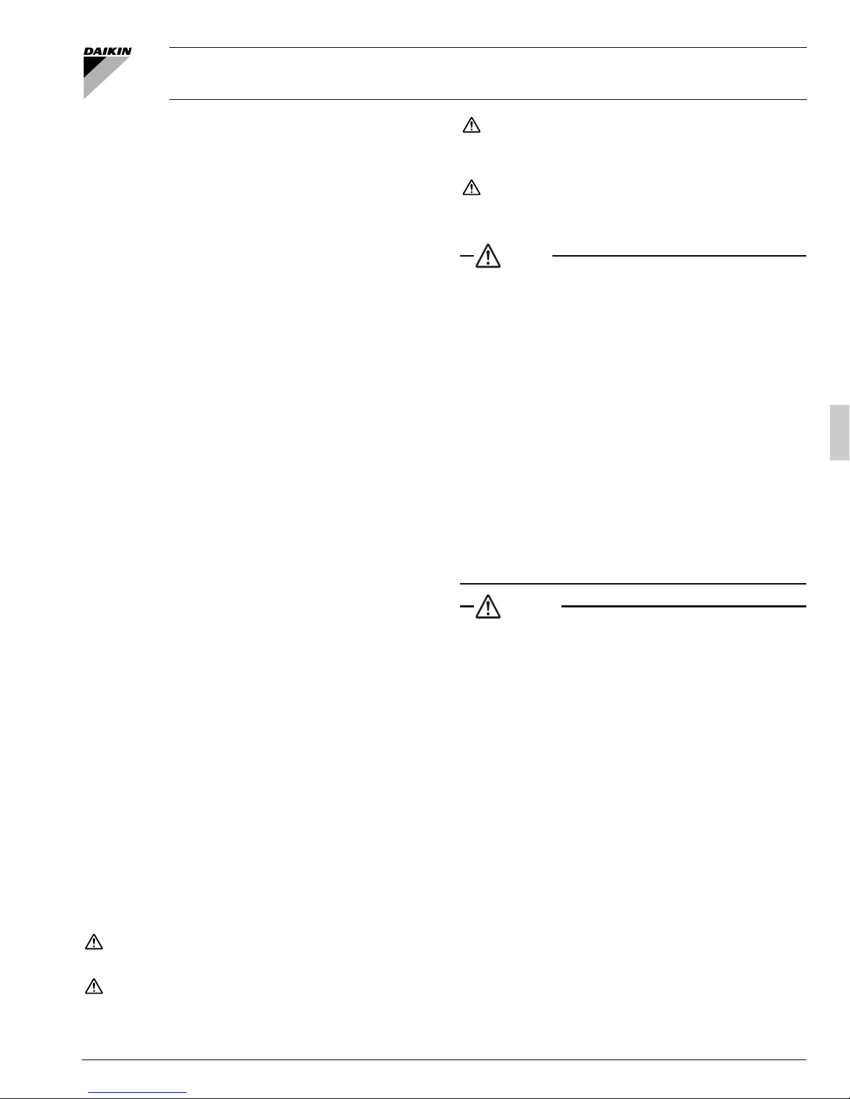
9-10 Stop valve operation procedure ......................................... 16
10. CHECKS AFTER INSTALLATION ............................................. 17
11. TEST RUN ................................................................................. 17
11-1 Air discharge ...................................................................... 17
11-2 Before turn on the power supply ........................................ 17
11-3 Check operation ................................................................. 17
11-4 Check of normal operation ................................................. 18
12. ONSITE SETTINGS ................................................................... 18
12-1 Energy saving and optimum operation............................... 18
13. CAUTION FOR REFRIGERANT LEAKS ................................... 21
1. SAFETY CONSIDERATIONS
Read these SAFETY CONSIDERATIONS for Installation carefully
before installing air conditioning equipment. After completing the installation, make sure that the unit operates properly during the startup operation.
Instruct the customer on how to operate and maintain the unit. Inform
customers that they should store this Installation Manual with the Operation Manual for future reference.
Always use a licensed installer or contractor to install this product.
Improper installation can result in water or refrigerant leakage, electrical
shock, fire, or explosion.
Meanings of DANGER, WARNING, CAUTION, and NOTE Symbols:
DANGER .....................Indicates an imminently hazardous situa-
tion which, if not avoided, will result in
death or serious injury.
WARNING................... Indicates a potentially hazardous situation
which, if not avoided, could result in death
or serious injury.
CAUTION.................... Indicates a potentially hazardous situation
which, if not avoided, may result in minor or
moderate injury. It may also be used to
alert against unsafe practices.
NOTE.......................... Indicates situations that may result in
equipment or property-damage accidents
only.
DANGER
• Refrigerant gas is heavier than air and replaces oxygen. A
massive leak can lead to oxygen depletion, especially in basements, and an asphyxiation hazard could occur leading to serious injury or death.
• Do not ground units to water pipes, gas pipes, telephone
wires, or lightning rods as incomplete grounding can cause a
severe shock hazard resulting in severe injury or death. Additionally, grounding to gas pipes could cause a gas leak and
potential explosion causing severe injury or death.
• If refrigerant gas leaks during installation, ventilate the area
immediately. Refrigerant gas may produce toxic gas if it
comes in contact with fire. Exposure to this gas could cause
severe injury or death.
• After completing the installation work, check that the refrigerant gas does not leak throughout the system.
• Do not install unit in an area where flammable materials are
present due to risk of explosions that can cause serious injury
or death.
• Safely dispose all packing and transportation materials in accordance with federal/state/local laws or ordinances. Packing
materials such as nails and other metal or wood parts, including plastic packing materials used for transportation may
cause injuries or death by suffocation.
WARNING
• Only qualified personnel must carry out the installation work.
Installation must be done in accordance with this installation
manual. Improper installation may result in water leakage,
electric shock, or fire.
• When installing the unit in a small room, take measures to keep
the refrigerant concentration from exceeding allowable safety
limits. Excessive refrigerant leaks, in the event of an accident in
a closed ambient space, can lead to oxygen deficiency.
• Use only specified accessories and parts for installation work.
Failure to use specified parts may result in water leakage,
electric shocks, fire, or the unit falling.
• Install the air conditioner on a foundation strong enough that it
can withstand the weight of the unit. A foundation of insufficient strength may result in the unit falling and causing injuries.
• Take into account strong winds, typhoons, or earthquakes
when installing. Improper installation may result in the unit
falling and causing accidents.
• Make sure that a separate power supply circuit is provided for
this unit and that all electrical work is carried out by qualified
personnel according to local, state and national regulations.
An insufficient power supply capacity or improper electrical
construction may lead to electric shocks or fire.
• Make sure that all wiring is secured, that specified wires are
used, and that no external forces act on the terminal connections or wires. Improper connections or installation may result in fire.
English 1

• When wiring, position the wires so that the control box cover
can be securely fastened. Improper positioning of the control
box cover may result in electric shocks, fire, or the terminals
overheating.
• Before touching electrical parts, turn off the unit.
• This equipment can be installed with a Ground-Fault Circuit
Interrupter (GFCI). Although this is a recognized measure for
additional protection, with the grounding system in North
America, a dedicated GFCI may not be necessary.
• Securely fasten the outside unit terminal cover (panel). If the
terminal cover/panel is not installed properly, dust or water
may enter the outside unit causing fire or electric shock.
• When installing or relocating the system, keep the refrigerant
circuit free from substances other than the specified refrigerant (R410A) such as air. Any presence of air or other foreign
substance in the refrigerant circuit can cause an abnormal
pressure rise or rupture, resulting in injury.
• Do not change the setting of the protection devices. If the
pressure switch, thermal switch, or other protection device is
shorted and operated forcibly, or parts other than those specified by Daikin are used, fire or explosion may occur.
• Indoor and outside units are for indoor installation only.
• Do not install the air conditioner in the following locations:
(a) Where a mineral oil mist or oil spray or vapor is produced,
for example, in a kitchen.
Plastic parts may deteriorate and fall off or result in water
leakage.
(b) Where corrosive gas, such as sulfurous acid gas, is pro-
duced.
Corroding copper pipes or soldered parts may result in
refrigerant leakage.
(c) Near machinery emitting electromagnetic waves.
Electromagnetic waves may disturb the operation of the
control system and cause the unit to malfunction.
(d) Where flammable gas may leak, where there is carbon fiber,
or ignitable dust suspension in the air, or where volatile
flammables such as thinner or gasoline are handled. Operating the unit in such conditions can cause a fire.
• Take adequate measures to prevent the outside unit from be-
ing used as a shelter by small animals. Small animals making
contact with electrical parts can cause malfunctions, smoke,
or fire. Instruct the customer to keep the area around the unit
clean.
CAUTION
• Do not touch the switch with wet fingers. Touching a switch
with wet fingers can cause electric shock.
• Do not allow children to play on or around the unit to prevent
injury.
• Do not touch the refrigerant pipes during and immediately after operation as the refrigerant pipes may be hot or cold, depending on the condition of the refrigerant flowing through
the refrigerant piping, compressor, and other refrigerant cycle
parts. Your hands may suffer burns or frostbite if you touch
the refrigerant pipes. To avoid injury, give the pipes time to return to normal temperature or, if you must touch them, be sure
to wear proper gloves.
• Heat exchanger fins are sharp enough to cut.
To avoid injury wear glove or cover the fins when working
around them.
• Install drain piping to proper drainage. Improper drain piping
may result in water leakage and property damage.
• Insulate piping to prevent condensation.
• Be careful when transporting the product.
• Do not turn off the power supply immediately after stopping
operation. Always wait for at least 5 minutes before turning off
the power supply. Otherwise, water leakage may occur.
• Do not use a charging cylinder. Using a charging cylinder may
cause the refrigerant to deteriorate.
• Refrigerant R410A in the system must be kept clean, dry, and
tight.
(a) Clean and Dry -- Foreign materials (including mineral oils
such as SUNISO oil or moisture) should be prevented from
getting into the system.
(b) Tight -- R410A does not contain any chlorine, does not
destroy the ozone layer, and does not reduce the earth’s protection again harmful ultraviolet radiation. R410A can contribute to the greenhouse effect if it is released. Therefore
take proper measures to check for the tightness of the refrigerant piping installation. Read the chapter Refrigerant Piping and follow the procedures.
• Since R410A is a blend, the required additional refrigerant
must be charged in its liquid state. If the refrigerant is charged
in a state of gas, its composition can change and the system
will not work properly.
• The indoor unit is for R410A. See the catalog for indoor models that can be connected. Normal operation is not possible
when connected to other units.
• Remote controller (wireless kit) transmitting distance can be
shorter than expected in rooms with electronic fluorescent
lamps (inverter or rapid start types). Install the indoor unit far
away from fluorescent lamps as much as possible.
NOTE
• Install the power supply and transmission wires for the indoor
and outside units at least 3.5 feet (1 m) away from televisions
or radios to prevent image interference or noise. Depending
on the radio waves, a distance of 3.5 feet (1 m) may not be sufficient to eliminate the noise.
• Dismantling the unit, treatment of the refrigerant, oil and additional parts must be done in accordance with the relevant local, state, and national regulations.
• Do not use the following tools that are used with conventional
refrigerants: gauge manifold, charge hose, gas leak detector,
reverse flow check valve, refrigerant charge base, vacuum
gauge, or refrigerant recovery equipment.
• If the conventional refrigerant and refrigerator oil are mixed in
R410A, the refrigerant may deteriorate.
• This air conditioner is an appliance that should not be accessible to the general public.
• The wall thickness of field-installed pipes should be selected
in accordance with the relevant local, state, and national regulations.
Codes and Regulations
This product is designed and manufactured to comply with national
codes. Installation in accordance with such codes and/or prevailing
local codes/regulations is the responsibility of the installer. The manufacturer assumes no responsibility for equipment installed in violation of
any codes or regulations. Rated performance is achieved after charge
adjustment (sub-cooling of 14±1°F (8±0.5°C) and superheat of 3±1°F
(1.7±0.5°C)) and 72 hours of operation.
2 English

2. INTRODUCTION
This installation manual concerns VRV inverters of the Daikin
RWEYQ-PC series. These units are designed for indoor installation and
used for cooling and heat pump applications.
The RWEYQ-PC units can be combined with Daikin VRV series indoor
units for air conditioning purposes.
The present installation manual describes the procedures for unpacking, installing and connecting the RWEYQ-PC units. Installation of the
indoor units is not described in this manual. Always refer to the installation manual supplied with these units for their installation.
2-1 Combination
The indoor units can be installed in the following range.
• Always use appropriate indoor units compatible with R410A.
To learn which models of indoor units are compatible with
R410A, refer to the product catalogs.
• The Branch Selector units that combined with RWEYQ-PC units for
changing the refrigerant flow to indoor units are T type (BSQ-TVJ,
BS-Q54TVJ) only, or P type (BSVQ-PVJU, BSV-Q36PVJU) only. Do
not combine the T type and P type in the system. Combination of T
type and P type cause malfunction.
• Total capacity/quantity of indoor units
〈Outside unit〉〈Total capacity index of indoor units〉〈Total quantity of indoor units〉
RWEYQ72PCYD/CTJ
RWEYQ84PCYD/CTJ
RWEYQ144PCYD/CTJ
RWEYQ168PCYD/CTJ
RWEYQ216PCYD/CTJ
RWEYQ252PCYD/CTJ
2-2 Standard operation limit
The figures below assume following operating conditions for indoor and
outside units:
Equivalent pipe length ........................................25 ft. (7.6 m)
Level difference..................................................................... 0
Cooling Heating
120
110
100
90
80
70
60
50
6050 70 80 90 6050 70 80 90
〈In case of antifreeze usage〉
Cooling Heating
120
110
100
90
80
70
60
50
40
30
20
6050 70 80 90 6050 70 80 90
A Entering water temperature (°F)
B Indoor temperature (°FWB)
C Indoor temperature (°FDB)
Range for continuous operation
Range for operation
Range for pull down operation
Range for warming up operation
......... 36-93.5 12 units
......... 42-109 14 units
....... 72-187 24 units
....... 84-218 29 units
..... 108-280 36 units
..... 126-327.5 36 units
AA
120
110
100
90
80
70
60
50
CB
AA
110
100
90
80
70
60
50
40
30
20
10
CB
• Operation range of water flow rate is 13.2-39.6 gpm (50-150 L/min).
(21.2-39.6 gpm (80-150 L/min) in case of antifreeze usage.)
• The unit is designed for the following operation range;
Entering water temperature: 67-95°F (20-35°C)
Water flow rate: 15.9gpm (60L/min) or more
• During cooling operation when the outside temperature is very low, it
is possible that the thermostat switches off automatically in order to
protect the unit from freezing.
• Hold ambient temperature at 35-104°FDB (2-40°CDB).
Heat release from the unit (approx.): RWEYQ72: 2200 Btu/h
(0.64kW), RWEYQ84: 2450 Btu/h (0.71kW)
It is therefore recommended to always ventilate the room.
2-3 Standard supplied accessories
• Make sure that the following accessories are included.
(Check by removing the front panel.)
Name
For discharge
gas
For suction
Quantity 1 pc. 1 pc. 1 pc. 7 pcs. 2 pcs.
(Note)
Shape
Name Conduit mounting plate
Quantity 2 pcs. 2 pcs.
Shape
gas (1)
Accessory pipes
For suction
gas (2)
[Others]
•
Installation manual
•
Operation manual
Clamp (A) Clamp (B)
White
Black
(Refer to figure 1)
1. • Operation manual
• Installation manual
•Clamp (A)
•Clamp (B)
• Conduit mounting plate
2. Accessory pipes
• For discharge gas
• For suction gas (1)
• For suction gas (2)
NOTE
The accessory pipe for discharge gas is used for the heat recovery system. (Not used for the heat pump system.)
2-4 Option accessories
To install the above outside units, the following optional parts are also
required.
• Refrigerant branch kit
(For R410A only: Always use an appropriate kit dedicated for your
system.)
〈Heat pump system〉
REFNET header
REFNET joint
〈Heat recovery system ..... For 3-tube piping〉
REFNET header
REFNET joint
〈Heat recovery system ..... For 2-tube piping〉
REFNET header
REFNET joint
• Outside unit multi connection piping kit
(For R410A only: Always use an appropriate kit dedicated for
your system.)
Number of outside units
connected
Heat pump system BHFP22MA56U BHFP22MA84U
Heat recovery system BHFP26MA56U BHFP26MA84U
∗ To select an optimum kit, refer to 9. REFRIGERANT PIPING
KHRP26M22H9 KHRP26M33H9 KHRP26M72H9
KHRP26A22T9 KHRP26A33T9
KHRP26M72TU9 KHRP26M73TU9
KHRP25M33H9 KHRP25M72H9
KHRP25A22T9 KHRP25A33T9
KHRP26M22H9 KHRP26M33H9
KHRP26A22T9 KHRP26A33T9
KHRP25M72TU9 KHRP25M73TU9
KHRP26M72H9 KHRP26M73HU9
KHRP26M72TU9 KHRP26M73TU9
2 units 3 units
KHRP26M73HU9
KHRP25M73HU9
English 3
 Loading...