

Daikin RCS 06F, RCS 20F Installation Manual
© 2013 Daikin Applied
Installation Manual IM 962-2
Group: Applied Air Systems
Air-Cooled Split System Condensing Units
Models RCS 06F – 20F
6.5 to 20 Tons
R-410A Refrigerant
Part Number: IM 962-2
Date: August 2013
15.0 – 20.0 Tons
6.5 – 7.5 Tons
10.0 – 12.0 Tons

Table of Contents
Introduction .................................3
Hazard Identication Information ................3
Checking Product Received ....................3
Standard Unit Features .......................4
Dimensional and Weight Data ..................6
Physical Data ................................8
Unit Capacity and Physical Data . . . . . . . . . . . . . . . . 8
Electrical Data ...............................9
Power Wiring . . . . . . . . . . . . . . . . . . . . . . . . . . . . . . . 9
Installation .................................10
Order Parts ...............................10
Standard Items .............................10
Crankcase Heaters .........................10
Corrosive Environment ......................10
Installation General .........................10
Rooftop Installation ..........................11
Slab Installation . . . . . . . . . . . . . . . . . . . . . . . . . . . . 11
Installation of Piping .........................12
Typical Piping Recommendations ..............12
Electrical Wiring ............................14
Refrigerant Charge ..........................16
Evaporator Coil ............................17
Evacuation and Charging .....................17
Final Leak Testing ..........................18
Accessory Installation .......................19
Maintenance and Operation ...................20
Charging Charts ............................21
Wiring Diagrams ............................27
Service and Warranty Procedure ...............29
Replacement Parts .........................29
In-Warranty Return Material Procedure ..........29
Warranty Registration Form ...................30
Quality Assurance Survey Form................32
2 IM 962-2
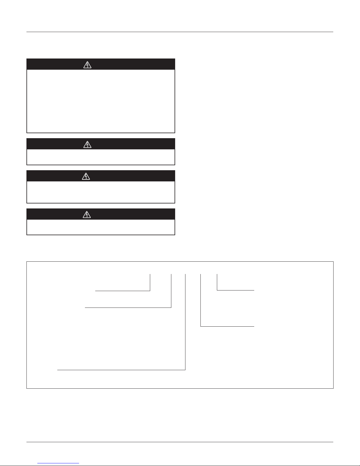
Hazard Identication Information
DANGER
The use of unauthorized components, accessories or devices
may adversely affect the operation of the condensing unit and
may also endanger life and property.
The manufacturer disclaims any responsibility for such loss
or injury and the manufacturer’s warranty does not cover
any damage or defect to the air conditioner caused by the
attachment or use of any components, accessories or devices
(other than those authorized by the manufacturer) into, onto
or in conjunction with the condensing unit.
DANGER
Dangers indicate a hazardous situation which will result in
death or serious injury if not avoided.
WARNING
Warnings indicate potentially hazardous situations, which
canresult in property damage, severe personal injury, or death
ifnot avoided.
Introduction
Introduction
This manual contains the installation and operating
instructions for your split condensing unit. There are a
few precautions that should be taken to derive maximum
satisfaction from it. Improper installation can result in
unsatisfactory operation or dangerous conditions.
Read this manual and any instructions packaged with separate
equipment required to make up the system prior to installation.
Give this manual to the owner and explain its provisions. The
owner should retain this manual for future reference.
Checking Product Received
Upon receiving the unit, inspect it for any damage from
shipment. Claims for damage, either shipping or concealed,
should be led immediately with the shipping company.
Check the unit model number, electrical characteristics, and
accessories to determine if they are correct.
CAUTION
Cautions indicate potentially hazardous situations, which can
result in personal injury or equipment damage if not avoided.
Nomenclature
R C S – 06 – F – 078 – C
Rooftop Condensing System
Nominal capacity (tons)
06 = 6.5
07 = 7.5
10 = 10 (single compressor)
11 = 10 (tandem compressors)
12 = 12
15 = 15
20 = 20
Refrigerant
F = R-410A
Voltage
C = 208/230 - 3 - 60
D = 460 - 3 - 60
Y = 575 - 3 - 60
Compressor
078 = 6.5 ton, single
090 = 7.5 ton, single
120 = 10 ton, single
125 = 10 ton, tandem
150 = 12.5 ton, tandem
180 = 15 ton, tandem
240 = 20 ton, tandem
NOTE: For larger size units (greater than 20 ton), refer to Catalog 222.
IM 962-2 3

Introduction
Introduction
Standard Unit Features
Cabinet — Galvanized steel with a durable powder paint
nish. Stamped louvered panels offer 100% protection for the
condenser coil.
Compressor — Hermetically sealed scroll compressors.
Compressors are mounted on rubber-in-shear pads to reduce
vibration and noise.
Condenser Coil — Constructed with copper tubes and
aluminum ns mechanically bonded to the tubes for
maximum heat transfer capabilities. All coil assemblies are
leak tested at 450 psig internal pressure.
Refrigerant Connections — Field piping connections are made
through a xed panel. This allows complete access or removal of
access panels after piping connections have been made.
Crankcase Heater — Standard, all models.
Low Ambient Control — A pressure sensitive fan cycling
control to allow unit operation to 0°F is standard.
Service Valves — Standard on liquid lines and vapor lines.
Service Access — The control box, as well as the
compressor and other refrigerant controls, is accessible
through access panels. It may be opened without affecting
the normal operation of the unit. Condenser fan motors are
accessible by removing wire grilles.
Filter Drier — Field supplied.
Sight Glass — Optional, eld supplied.
Transformer — Step down type, line to 24 volts.
Contactor — The contactor is an electrical switch which
operates the compressor and condenser fans.
High Pressure Control — Opens the contactor circuit on
high refrigerant pressure; manual reset.
Low Pressure Control — Stops compressor operation in the
event of loss of refrigerant.
Condenser Fan Motor (Direct Drive) — Ball bearing 1075
RPM motors are mounted to minimize vibration and noise
problems.These are permanent split capacitor types and
require the same capacitance for both run and start.
Testing — All units are run tested at the factory prior to
shipment. Units are shipped with a holding pressure of nitrogen.
Figure 1: RCS 06F & 07F Ton Features
4 IM 962-2
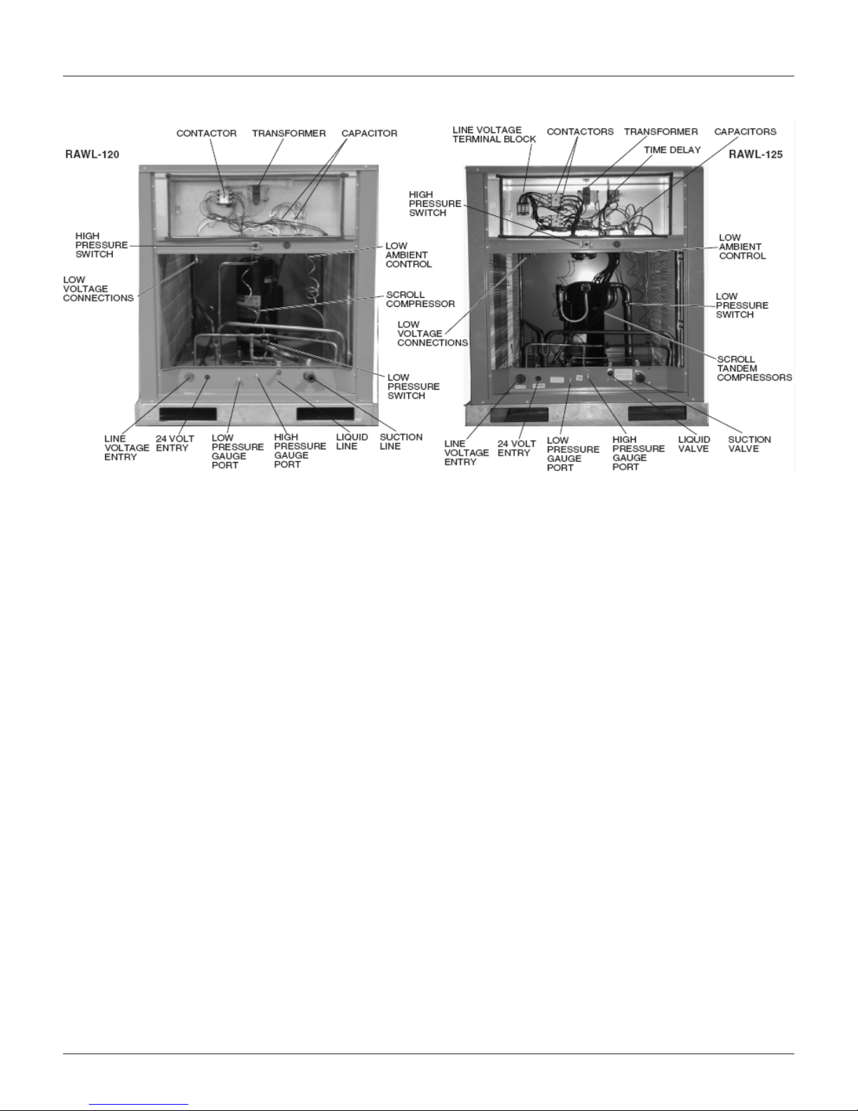
Figure 2: RCS 10F – 20F Ton Features
Introduction
IM 962-2 5
Dimensional and Weight Data
Dimensional and Weight Data
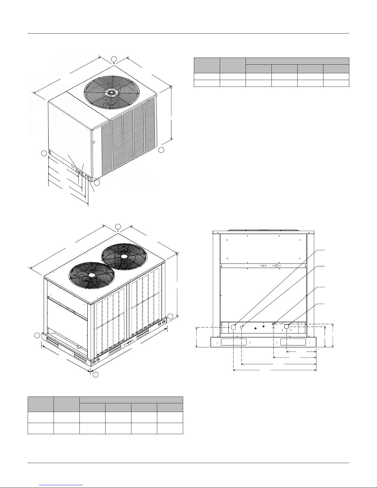
Figure 3: RCS 06F and 07F Dimensions and Weights Table 1: RCS 06F and 07F Operating Weights
43.00
CONTROL
PANEL ACCESS
C
31.06
RCS
model
06F 291 [132] 50 [22.7] 73 [33.1] 69 [31.3] 99 [44.9]
07F 318 [144] 53 [24.0] 84 [38.1] 71 [32.2] 110 [49.9]
32.81
Total
weight
lbs. [kg]
Corner weight lbs. [kg]
A B C D
D
SUCTION
LINE 1
21.69
24.19
26.63
28.44
1/8"
LIQUID
LINE
1/2"
HIGH VOLTAGE
B
3/4"
DIA. HOLE1
LOW VOLTAGE
7/8"
DIA. HOLE
A
Figure 4: RCS 10F and 11F Dimensions and Weights
B
38.375
60.625
CONTROL
PANEL ACCESS
High Voltage
1-3/4" Dia. Hole
Low Voltage
7/8" Dia. Hole
44.75
D
Liquid Line
5/8" Dia. Hole
Suction Line
1-3/8" Dia. Hole
A
39.94
C
Table 2: RCS 10F and 11F Operating Weights
RCS
model
10F
(Single)
11F
(Tandem)
Total
weight
lbs. [kg]
501 [228] 123 [53.9] 132 [60.0] 119 [54.1] 127 [58.0]
586 [266] 144 [65.3] 154 [69.9] 139 [63.2] 149 [67.6]
Corner weight lbs. [kg]
A B C D
6 IM 962-2
62.125
8.75
7.5
11.25
16.25
28.25
31.25
7.875
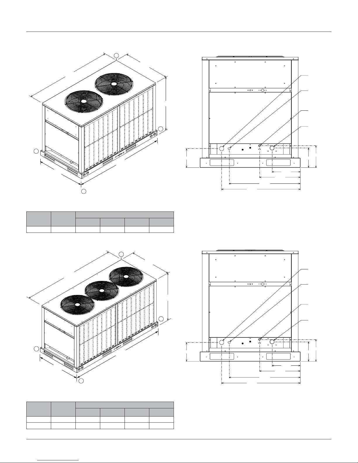
Figure 5: RCS 12F Dimensions and Weights
Dia. I.D. 15 Ton
Dia. I.D. 20 Ton
B
Dimensional and Weight Data
Dimensional and Weight Data
38.375
72.375
CONTROL
PANEL ACCESS
A
73.88
39.94
C
Table 3: RCS 12F Operating Weights
RCS
model
Total
weight
lbs. [kg]
12F 650 [293] 160 [72.0] 171 [78.0] 154 [70.0] 165 [75.0]
Corner weight lbs. [kg
A B C D
Figure 6: RCS 15F – 20F Dimensions and Weights
High Voltage
1-3/4" Dia. Hole
Low Voltage
7/8" Dia. Hole
44.75
D
7.5
11.25
16.25
28.25
31.25
Liquid Line
5/8" Dia. Hole
Suction Line
1-3/8" Dia. Hole
8.75
7.875
B
38.375
87.375
CONTROL
PANEL ACCESS
A
39.94
C
88.88
Table 4: RCS 15F and 20F Operating Weights
RCS
model
Total
weight
lbs. [kg]
15F 746 [338.0] 183 [83.0] 196 [89.0] 177 [80.0] 189 [86.0]
20F 952 [432.0] 234 [106.0] 251 [114.0] 226 [103.0] 241 [110.0]
Corner weight lbs. [kg]
A B C D
High Voltage
1-3/4" Dia. Hole
Low Voltage
7/8" Dia. Hole
44.75
D
7.5
11.25
16.25
28.25
31.25
Liquid Line
Liquid Line
5/8" Dia. Hole
5/8"
7/8"
Suction Line
Suction Line
1-5/8" Dia. Hole
1-3/8" Dia. Hole
8.75
7.875
IM 962-2 7
Physical Data
Physical Data
Unit Capacity and Physical Data
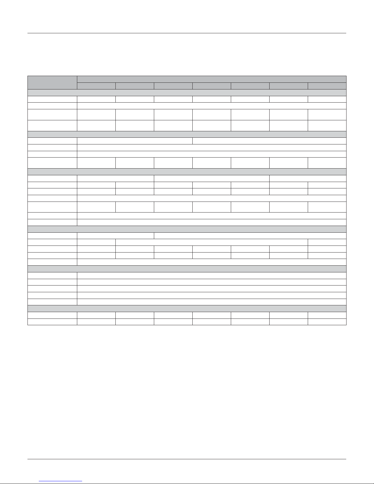
Table 5: RCS 06F – 20F Physical Data
Model
Capacity and Weight
Capacity (tons) [kW] 6.5 [22.9] 7.5 [26.4] 10 [35.2] 10 [35.2] 12 [42.2] 15 [52.8] 20 [70.3]
Number of circuits 1
Operating weight
(lbs) [Kg]
Shipping weight
(lbs) [Kg]
Compressor
Quantity 1 2
Type Scroll
RPM 3500
Refrigerant charge
R410A oz. [g]
Condenser Fans
Quantity 1 2 3
CFM [L/s] 4700 [2218] 4700 [2218] 8100 [3822] 8100 [3822] 8100 [3882] 12,000 [5663] 12,000 [5663]
Diameter (in.) [mm 24 [610] 24 [610] 24 [610] 24 [610] 24 [610] 24 [610] 24 [610]
Drive Direct
Motor horsepower
each [W]
Type PSC
RPM 1075
Condenser Coil
Quantity 1 2
Rows 1-1/2 2 3
Fins per inch 20 22 18 22 22 22 22
Cabinet
Sheet metal Galvanized
Gauge (nominal) top 20
Refrigerant Connection
Vapor sweat (in.) [mm] 1-1/8 [29] 1-1/8 [29] 1-3/8 [35] 1-3/8 [35] 1-3/8 [35] 1-5/8 [41.3] 1-5/8 [41.3]
Liquid sweat (in.) [mm] 1/2 [13] 1/2 [13] 5/8 [16] 5/8 [16] 5/8 [16] 5/8 [16] 7/8 [22]
2
Sq. ft. [m
Fins/tubes Aluminum/Copper
Base rails 14
] 23.0 [2.14] 23.0 [2.14] 27.0 [2.51] 27.0 [2.51] 33.9 [3.05] 40.38 [3.75] 40.38 [3.75]
Finish Powder Coat
Sides 20
06F Single 07F Single 10F Single 11F Tandem 12F Tandem 15F Tandem 20F Tandem
291 [132] 318 [144] 501 [227.3] 586 [265.8] 650 [294.8] 746 [338.4] 952 [431.8]
314 [142.5] 341 [154.7] 541 [245.4] 626 [284.0] 690 [313.0] 786 [356.5] 992 [450.0]
178 [5046] 242 [6861] 339 [9661] 300 [8505] 378 [10,716] 506 [14,345] 655 [18,569]
1/3 [249] 1/3 [249] 1/3 [249] 1/3 [249] 1/3 [249] 1/3 [249] 1/3 [249]
RCS
8 IM 962-2

Electrical Data
Power Wiring
Table 6: RCS 06F – 20F Electrical Data
Model
Compressor Motor
Voltage 208/230 460- 575 208/230 460 575 208/230 460 575 208/230 460 575 208/230 460 575 208/230 460 575 208/230 460 575
Phase and hertz 3 – 60
Number of compressors Single Tandem
Operating Current
Rated load amps (each)
Locked rotor amps (each)
Condenser Fan Motors
Voltage 208/230 460 575 208/230 460 575 208/230 460 575 208/230 460 575 208/230 460 575 208/230 460 575 208/230 460 575
Phase Single
Full load amps (each) 2.2 1.3 1.0 2.2 1.3 1.0 2.4 1.4 1.0 2.4 1.4 1.0 2.4 1.4 1.0 2.4 1.4 1.0 2.4 1.1 0.8
System characteristics
Unit full load amps
Minimum circuit ampacity 31.0 15.0 11.0 34.0 17.0 13.0 43.0 24.0 18.0 45.0 25.0 16.0 56.0 27.0 20.0 64.0 32.0 24.0 83.0 44.0 32.0
Maximum fuse size (amps)
or HACR circuit breaker
ampacity
Disconnect size 60 30 30 60 30 30 60 40 25 60 30 30 60 30 30 100 60 60 200 60 60
Note:
1 Each compressor
2 Conditions at 45° suction and 95° ambient
3 Local codes take precedent over recommended fuse size
1
1
2
3
06F 07F 10F 11F 12F 15F 20F
22.4 10.6 7.7 25.0 12.2 9.0 30.1 16.7 12.2 17.6 9.6 6.1 22.4 10.6 7.7 25.0 12.2 9.0 33.3 17.9 12.8
149 75 54 164 100 78 225 114 80 123 64 40 14 75 54 164 100 78 239 125 80
24.6 11.9 8.7 27.2 13.5 10.0 34.9 19.5 14.2 40.0 22.0 14.2 49.6 24.0 17.4 57.2 28.6 21.0 73.8 39.1 28.0
50 25 15 50 25 20 60 40 25 60 30 20 70 35 25 80 40 30 11 0 60 40
RCS
Electrical Data
Figure 7: Control Box Example – RCS 10F Through 20F
IM 962-2 9
Installation
Installation
Order Parts
When reporting shortages or damaged parts, or when
ordering repair parts, give the complete unit model and serial
numbers which are stamped on the unit rating plate.
Standard Items
The condensing unit consists of a completely assembled
package which includes a compressor pack, condenser coils,
fans, fan motors, outdoor control box, factory wiring, factory
tubing and ttings.
Crankcase Heaters
These units are equipped with a crankcase heater that is
factory wired to operate whenever the main power supply
to the unit is “ON” and compressors are “OFF.” Before
starting the equipment after prolonged shutdown or at the
time of initial spring startup, be sure that the circuits to the
condensing units are closed for at least 24 hours.
DANGER
Disconnect all power to unit before starting maintenance.
Failure to do so can cause electrical shock resulting in severe
personal injury or death.
Regular maintenance will reduce the buildup of contaminants
and help to protect the unit’s nish.
• Frequent washing of the cabinet, fan blade and coil
with fresh water will remove most of the salt or other
contaminants that build up on the unit.
• Regular cleaning and waxing of the cabinet with a good
automobile polish will provide some protection.
• A good liquid cleaner may be used several times a year
to remove matter that will not wash off with water.
Several different types of protective coatings are offered in
some areas. These coatings may provide some benet, but the
effectiveness of such coating materials cannot be veried by
the equipment manufacturer.
Corrosive Environment
The metal parts of this unit may be subject to rust or
deterioration if exposed to a corrosive environment. This
oxidation could shorten the equipment’s useful life. Corrosive
elements include salt spray, fog or mist in seacoast areas,
sulphur or chlorine from lawn watering systems, and various
chemical contaminants from industries such as paper mills
and petroleum reneries.
If the unit is to be installed in an area where contaminants are
likely to be a problem, special attention should be given to the
equipment location and exposure.
• Avoid having lawn sprinkler heads spray directly on the
unit cabinet
• In coastal areas, locate the unit on the side of the
building away from the waterfront.
• Shielding provided by a protection, based on clearances
Installation General
The condensing unit should be installed outdoors. It should be
located as near as possible to the evaporator section to keep
connecting refrigerant tubing lengths to a minimum. The unit
must be installed to allow a free air ow to the condenser coils
If several units are installed adjacent to each other, take care
to avoid recirculation of air from one condenser to another.
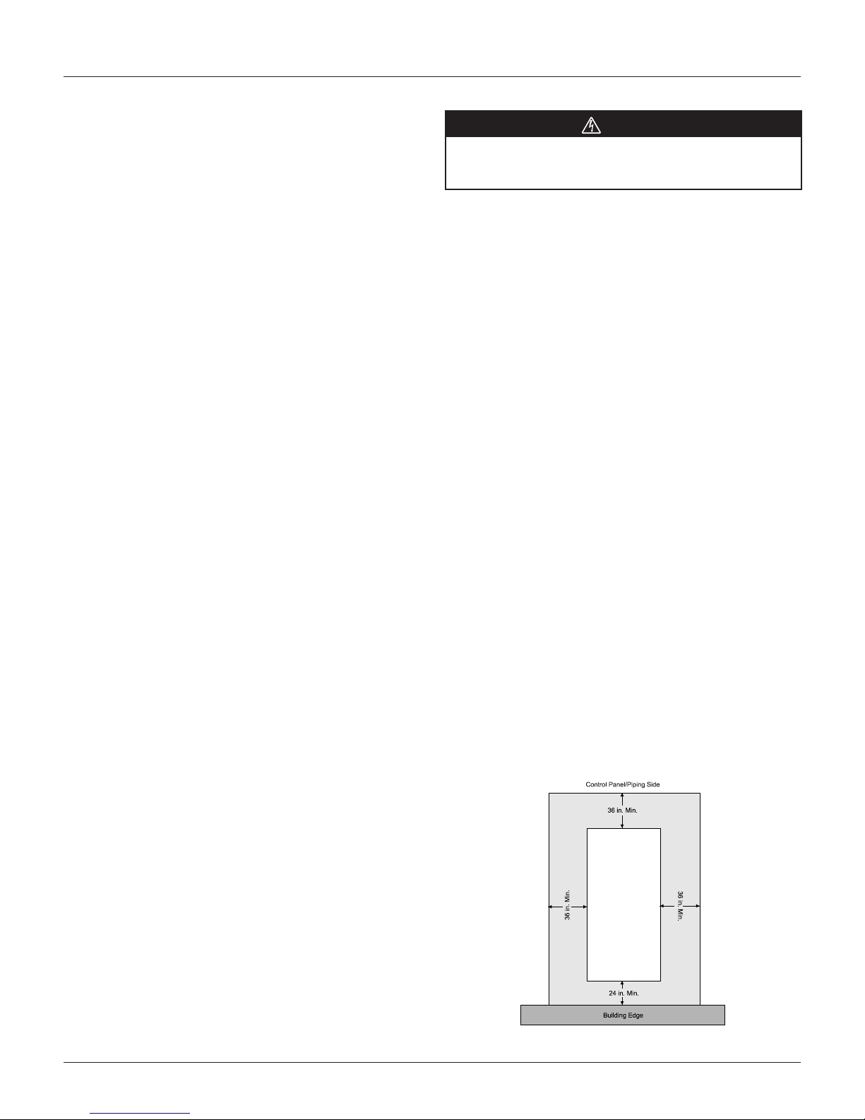
In all installations, adequate space must be provided for
installation and servicing.
The unit must not be connected to any duct work. Do not
locate unit under a roof drip; if necessary, install gutters,
etc., to prevent water runoff onto the unit. To prevent air
recirculation, it is recommended that the unit not be installed
under an overhang. However, if this is necessary, allow a
minimum of 60" above the unit for air discharge
Figure 8: Clearances RCS 06F – 20F Service Clearances
10 IM 962-2
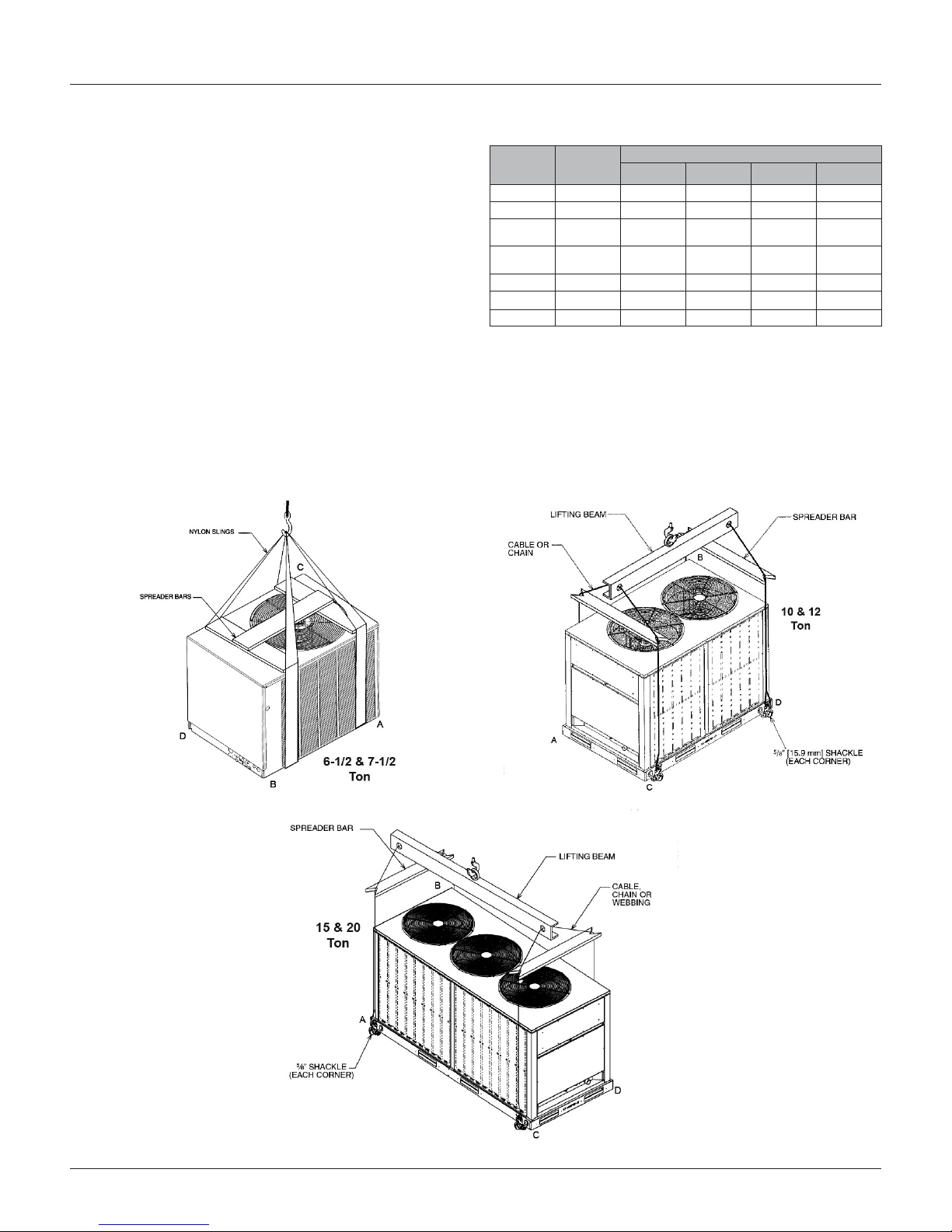
Rooftop Installation
If rooftop installation is required, make certain that the
building construction is adequate for the weight of the
unit. (Table 5 ) Before placing the unit on the roof, make
certain that the nylon rigging slings are of sufcient length
to maintain equilibrium of the unit when lifting. Under no
circumstances should the unit be lifted by only one corner for
rooftop installation.
Slab Installation
Condensing units should be set on a solid level foundation.
When installed at ground level, the unit should be placed on
a 6" cement slab. If the pad is formed at the installation site,
do not pour the pad tight against the structure, otherwise
vibration will be transmitted from the unit through the pad.
Figure 9: Rigging
Installation
Table 7: RCS 06F and 07F Operating Weights
RCS
model
06F 291 [132] 50 [22.7] 73 [33.1] 69 [31.3] 99 [44.9]
07F 318 [144] 53 [24.0] 84 [38.1] 71 [32.2] 110 [49.9]
10F
(Single)
11F
(Tandem)
12F 650 [293] 160 [72.0] 171 [78.0] 154 [70.0] 165 [75.0]
15F 746 [338.0] 183 [83.0] 196 [89.0] 177 [80.0] 189 [86.0]
20F 952 [432.0] 234 [106.0] 251 [114.0] 226 [103.0] 241 [110.0]
Total
weight
lbs. [kg]
501 [228] 123 [53.9] 132 [60.0] 119 [54.1] 127 [58.0]
586 [266] 144 [65.3] 154 [69.9] 139 [63.2] 149 [67.6]
Corner weight lbs. [kg]
A B C D
Installation
IM 962-2 11
 Loading...