

Daikin RFS-040c, RFS-135c, RCS-040c, RPS-045c, RDT-045c Installation And Maintenance Manual
...
Installation and Maintenance Manual IM 738-2
Roof
Pak® Singlezone Roof Mounted
Heating and Cooling Units
RPS/RDT/RFS/RCS 015–135C
Group:
Part Number: IM 738
Date: October 2018
Applied Air Systems

Contents
Introduction . . . . . . . . . . . . . . . . . . . . . . . . . . . . . . . . . . . . . . . 1
Unit Nameplate . . . . . . . . . . . . . . . . . . . . . . . . . . . . . . . . . . . . 1
Compressor Nameplate . . . . . . . . . . . . . . . . . . . . . . . . . . . . . 1
Gas Burner Nameplate . . . . . . . . . . . . . . . . . . . . . . . . . . . . . . 1
Hazard Identification Information . . . . . . . . . . . . . . . . . . . . . . . 1
Unit Description . . . . . . . . . . . . . . . . . . . . . . . . . . . . . . . . . . . . 2
Condenser Fan Arrangement . . . . . . . . . . . . . . . . . . . . . . . . . 4
Refrigeration Piping . . . . . . . . . . . . . . . . . . . . . . . . . . . . . . . . . 5
Control Locations . . . . . . . . . . . . . . . . . . . . . . . . . . . . . . . . . . 8
Control Panel . . . . . . . . . . . . . . . . . . . . . . . . . . . . . . . . . . . . . 10
Controls, Settings, and Functions . . . . . . . . . . . . . . . . . . . . . 18
Mechanical Installation . . . . . . . . . . . . . . . . . . . . . . . . . . . 21
Unit Clearances . . . . . . . . . . . . . . . . . . . . . . . . . . . . . . . . . . . 21
Ventilation Clearance . . . . . . . . . . . . . . . . . . . . . . . . . . . . . . 22
Overhead Clearance . . . . . . . . . . . . . . . . . . . . . . . . . . . . . . . 22
Roof Curb Assembly and Installation . . . . . . . . . . . . . . . . . . 23
Post and Rail Mounting . . . . . . . . . . . . . . . . . . . . . . . . . . . . . 26
Rigging and Handling . . . . . . . . . . . . . . . . . . . . . . . . . . . . . . 26
Reassembly of Split Units . . . . . . . . . . . . . . . . . . . . . . . . . . 29
Unit Piping . . . . . . . . . . . . . . . . . . . . . . . . . . . . . . . . . . . . . . . 44
Steam Coil Piping . . . . . . . . . . . . . . . . . . . . . . . . . . . . . . . . . 45
Damper Assemblies . . . . . . . . . . . . . . . . . . . . . . . . . . . . . . . 47
Cabinet Weather Protection . . . . . . . . . . . . . . . . . . . . . . . . . 49
Installing Ductwork . . . . . . . . . . . . . . . . . . . . . . . . . . . . . . . . 49
Installing Duct Static Pressure Sensor Taps . . . . . . . . . . . . . 50
. . . . . 51
Installing Building Static Pressure Sensor Taps
. . . . .
Electrical Installation . . . . . . . . . . . . . . . . . . . . . . . . . . . . . 52
Field Power Wiring . . . . . . . . . . . . . . . . . . . . . . . . . . . . . . . . 52
Field Control Wiring . . . . . . . . . . . . . . . . . . . . . . . . . . . . . . . . 55
Preparing Unit for Operation . . . . . . . . . . . . . . . . . . . . . 56
Spring Isolated Fans . . . . . . . . . . . . . . . . . . . . . . . . . . . . . . . 56
Relief Damper Tie-Down . . . . . . . . . . . . . . . . . . . . . . . . . . . . 56
Adjusting Scroll Dampers . . . . . . . . . . . . . . . . . . . . . . . . . . . 57
Adjusting Supply Fan Thrust Restraints . . . . . . . . . . . . . . . . 57
Sequences of Operation . . . . . . . . . . . . . . . . . . . . . . . . . . 58
Power-up . . . . . . . . . . . . . . . . . . . . . . . . . . . . . . . . . . . . . . . . 58
Fan Operation . . . . . . . . . . . . . . . . . . . . . . . . . . . . . . . . . . . . 58
Economizer Operation . . . . . . . . . . . . . . . . . . . . . . . . . . . . . . 59
Mechanical Cooling Operation . . . . . . . . . . . . . . . . . . . . . . . 59
Heating . . . . . . . . . . . . . . . . . . . . . . . . . . . . . . . . . . . . . . . . . 60
Wiring Diagrams . . . . . . . . . . . . . . . . . . . . . . . . . . . . . . . . . . 62
Legend . . . . . . . . . . . . . . . . . . . . . . . . . . . . . . . . . . . . . . . . . 62
Unit Options . . . . . . . . . . . . . . . . . . . . . . . . . . . . . . . . . . . . . . 88
Enthalpy Control . . . . . . . . . . . . . . . . . . . . . . . . . . . . . . . . . . 88
Hot Gas Bypass . . . . . . . . . . . . . . . . . . . . . . . . . . . . . . . . . . 89
SpeedTrol™ (N/A Unit Sizes 015C to 030C) . . . . . . . . . . . . 90
External Time Clock . . . . . . . . . . . . . . . . . . . . . . . . . . . . . . . 90
Smoke and Fire Protection . . . . . . . . . . . . . . . . . . . . . . . . . . 90
Freeze Protection . . . . . . . . . . . . . . . . . . . . . . . . . . . . . . . . . 91
Entering Fan Temperature Sensor . . . . . . . . . . . . . . . . . . . . 91
Duct High Pressure Limit . . . . . . . . . . . . . . . . . . . . . . . . . . . . 91
MicroTech II™ Remote User Interface (UI) . . . . . . . . . . . . . . 92
Variable Frequency Drive Operation . . . . . . . . . . . . . . . . . . . 93
. . . . . . . . . . . .93
Convenience Receptacle/Section Lights
DesignFlow™ Outdoor Air Damper Option . . . . . . . . . . . . . .93
Propeller Exhaust Fan Option . . . . . . . . . . . . . . . . . . . . . . . .96
Exhaust Fan On/Off Control . . . . . . . . . . . . . . . . . . . . . . . . . . 98
Ultraviolet Lights Option . . . . . . . . . . . . . . . . . . . . . . . . . . . . .98
Ultraviolet Light Operation . . . . . . . . . . . . . . . . . . . . . . . . . . . 99
. . . .
Check, Test, and Start Procedures . . . . . . . . . . . . . . 100
Servicing Control Panel Components . . . . . . . . . . . . . . . . . 100
Before Start-up . . . . . . . . . . . . . . . . . . . . . . . . . . . . . . . . . . . 100
Power Up . . . . . . . . . . . . . . . . . . . . . . . . . . . . . . . . . . . . . . . 101
Fan Start-up . . . . . . . . . . . . . . . . . . . . . . . . . . . . . . . . . . . . . 101
Economizer Start-up . . . . . . . . . . . . . . . . . . . . . . . . . . . . . . 101
Compressor Startup . . . . . . . . . . . . . . . . . . . . . . . . . . . . . . .102
Scroll Compressor Rotational Directio
Oil Pressure (sizes 115 to 135C only) . . . . . . . . . . . . . . . . . 103
Heating System Startup . . . . . . . . . . . . . . . . . . . . . . . . . . . . 104
Air Balancing . . . . . . . . . . . . . . . . . . . . . . . . . . . . . . . . . . . .104
Sheave Alignment . . . . . . . . . . . . . . . . . . . . . . . . . . . . . . . .105
Drive Belt Adjustment . . . . . . . . . . . . . . . . . . . . . . . . . . . . . 105
Mounting and Adjusting Motor Sheaves . . . . . . . . . . . . . . . 106
n (sizes 15 to 105)
. .102
Final Control Settings . . . . . . . . . . . . . . . . . . . . . . . . . . .109
Keypad accessible menu structure . . . . . . . . . . . . . . . . . . . 110
Maintenance . . . . . . . . . . . . . . . . . . . . . . . . . . . . . . . . . . . . .113
Servicing Control Panel Components . . . . . . . . . . . . . . . . . 113
Planned Maintenance . . . . . . . . . . . . . . . . . . . . . . . . . . . . . 113
Unit Storage . . . . . . . . . . . . . . . . . . . . . . . . . . . . . . . . . . . . . 113
Gas Furnace . . . . . . . . . . . . . . . . . . . . . . . . . . . . . . . . . . . . 114
Bearing Lubrication . . . . . . . . . . . . . . . . . . . . . . . . . . . . . . . 114
Setscrews . . . . . . . . . . . . . . . . . . . . . . . . . . . . . . . . . . . . . . 115
Supply Fan Wheel-to-Funnel Alignment . . . . . . . . . . . . . . . 116
Refrigerant Leaks . . . . . . . . . . . . . . . . . . . . . . . . . . . . . . . . . 117
Refrigerant Charge . . . . . . . . . . . . . . . . . . . . . . . . . . . . . . . 117
Servicing Refrigerant Sensors or Switches
Winterizing Water Coils . . . . . . . . . . . . . . . . . . . . . . . . . . . . 117
Control Panel Components . . . . . . . . . . . . . . . . . . . . . . . . .118
. .
. . . . . . . . . . .117
Replacement Parts List . . . . . . . . . . . . . . . . . . . . . . . . . .121
Service and Warranty Procedure . . . . . . . . . . . . . . . . 122
Replacement Parts . . . . . . . . . . . . . . . . . . . . . . . . . . . . . . . 122
Scroll Compressor (sizes 15 to 105C) . . . . . . . . . . . . . . . . . 122
Reciprocating Compressors (sizes 115 to 135C) . . . . . . . . 122
All Compressors . . . . . . . . . . . . . . . . . . . . . . . . . . . . . . . . . . 123
In-Warranty Return Material Procedure . . . . . . . . . . . . . . . . 123
Limited Product Warranty (North America) . . . . . . 124
Exceptions . . . . . . . . . . . . . . . . . . . . . . . . . . . . . . . . . . . . . . 124
Assistance . . . . . . . . . . . . . . . . . . . . . . . . . . . . . . . . . . . . . . 124
Sole Remedy . . . . . . . . . . . . . . . . . . . . . . . . . . . . . . . . . . . . 124
Rooftop Equipment Warranty
Registration Form . . . . . . . . . . . . . . . . . . . . . . . . . . 125
Quality Assurance Survey Report . . . . . . . . . . . . . . . 128
Daikin and MicroTech II are registered trademarks of Daikin Applied
Microsoft is a registered trademark of Microsoft Corporation.
Windows is a trademark of Microsoft Corporation.
Copyright © 2018 Daikin Applied. All rights reserved throughout the world.

Introduction
Introduction: Unit Nameplate
This manual provides general information about the “C”
vintage Daikin RoofPak applied rooftop unit, models RPS,
RDT, RFS and RCS. In addition to an overall description of
the unit, it includes mechanical and electrical installation
procedures, commissioning procedures, sequence of operation
information, and maintenance instructions. For further
information on the optional forced draft gas-fired furnace,
refer to Bulletin No. IM 684 or IM 685.
The MicroTech II applied rooftop unit controller is available
on “C” vintage applied rooftop units. For a detailed description
of the MicroTech II components, input/output configurations,
field wiring options and requirements, and service procedures,
see IM 696. For operation and information on using and
programming the MicroTech II unit controller, refer to the
appropriate operation manual (see
Table 1).
For a description of operation and information on using the
keypad to view data and set parameters, refer to the
appropriate program-specific operation manual (see Table 1)
.
Table 1: Program specific rooftop u nit op eration literature
Rooftop unit control configuration
VFDs Vendor IM manuals
Discharge Air Control (VAV or CAV) OM 137-2
Space Comfort Con trol
(CAV-Zone temperature control)
Operation manual bulletin
number
OM 138-2
Unit Nameplate
The unit nameplate is located on the outside lower right corner
on the main control box door. It includes the unit model
number, serial number, unit part number, electrical
characteristics, and refrigerant charge.
Compressor Nameplate
On units with a single compressor on each circuit, the
compressor includes one compressor nameplate.
On units that utilize the tandem
compressor design, each
compressor includes an individual nameplate along with a
nameplate identifying the tandem compressors.
Gas Burner Nameplate
On units that include gas heat, the nameplate is located on the
lower right corner on the main control box door. It includes the
burner model number, minimum/maximum input, maximum
temperature rise, and minimum CFM.
On units that utilize the tandem scroll
compressor design, each
compressor includes an individual nameplate along with a
nameplate identifying the tandem compressors.
On units that utilize the tande
m reciprocating design, each
compressor includes an individual nameplate.
Hazard Identification Information
WARNING
Warnings indicate potentially hazardous situations, which can
result in property damage, severe personal injury, or death if
not avoided.
CAUTION
Cautions indicate potentially hazardous situations, which can
result in personal injury or equipment damage if not avoided.
Figure 1. Nomenclature
R P S – 030 C S E
RoofPak
Unit configuration
P = Heating, mechanical cooling
F = Heating, future mechanical cooling
C = Condensing section only
D = Draw through cooling
Blow through cooling = S
Draw through cooling = T
Nominal capacity (tons)
RPS, RFS, RCS, RDT: 015, 018, 020, 025, 030, 036,
040, 045, 050, 060, 070, 075, 080, 090, 105, 115, 125, 135
IM 738-2 1
Heat medium
A = Natural gas
E = Electric
S = Steam
W = Hot water
Y = None (cooling only)
Cooling coil size
S=Standard (low airflow)
L =Large (high airflow)
Design vintage
Introduction: Unit Description
Unit Description
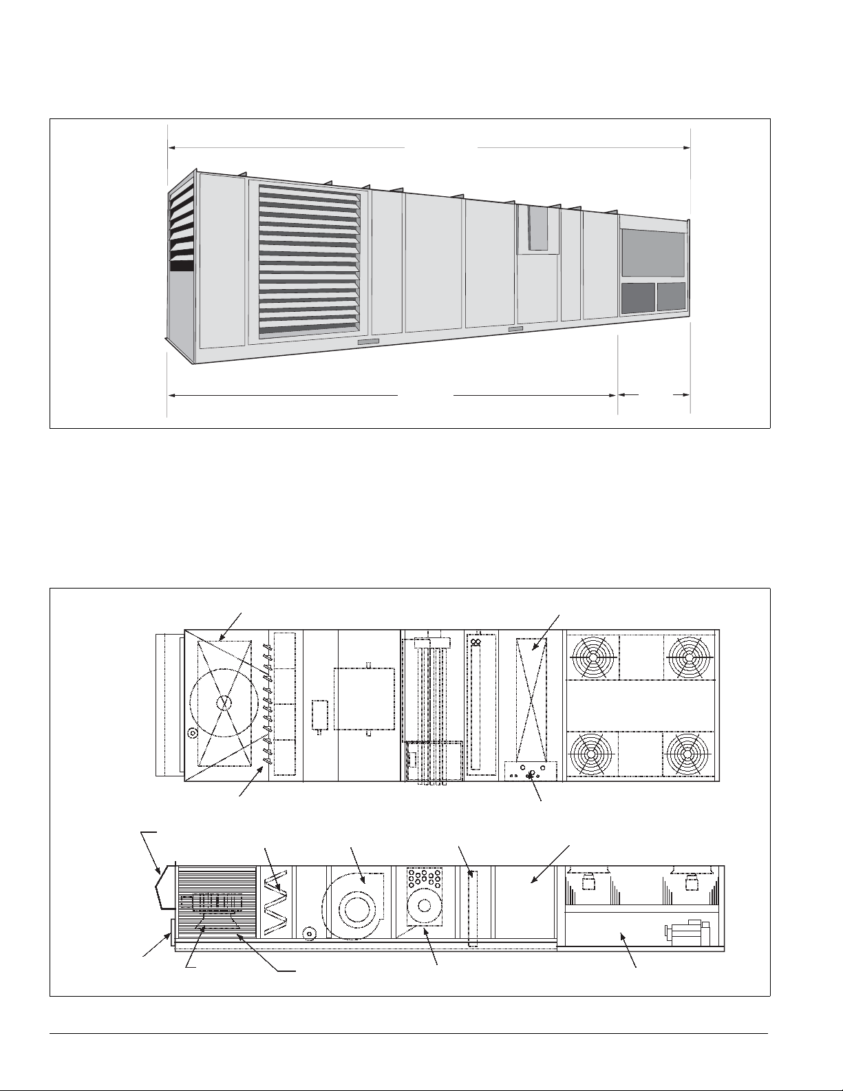
Figure 2. RPS/RDT/RFS/RCS unit
R P S / R D T
Typical Component Locations
Figure 2 shows an RPS/RDT/RFS/RCS unit. Figure 3 shows a
typical RPS unit with the locations of the major components.
Figure 4 on page 3 shows a typical RDT unit with the locations
of the major components. These figures are for general
information on
ly. See the project’s certified submittals for
actual specific dimensions and locations.
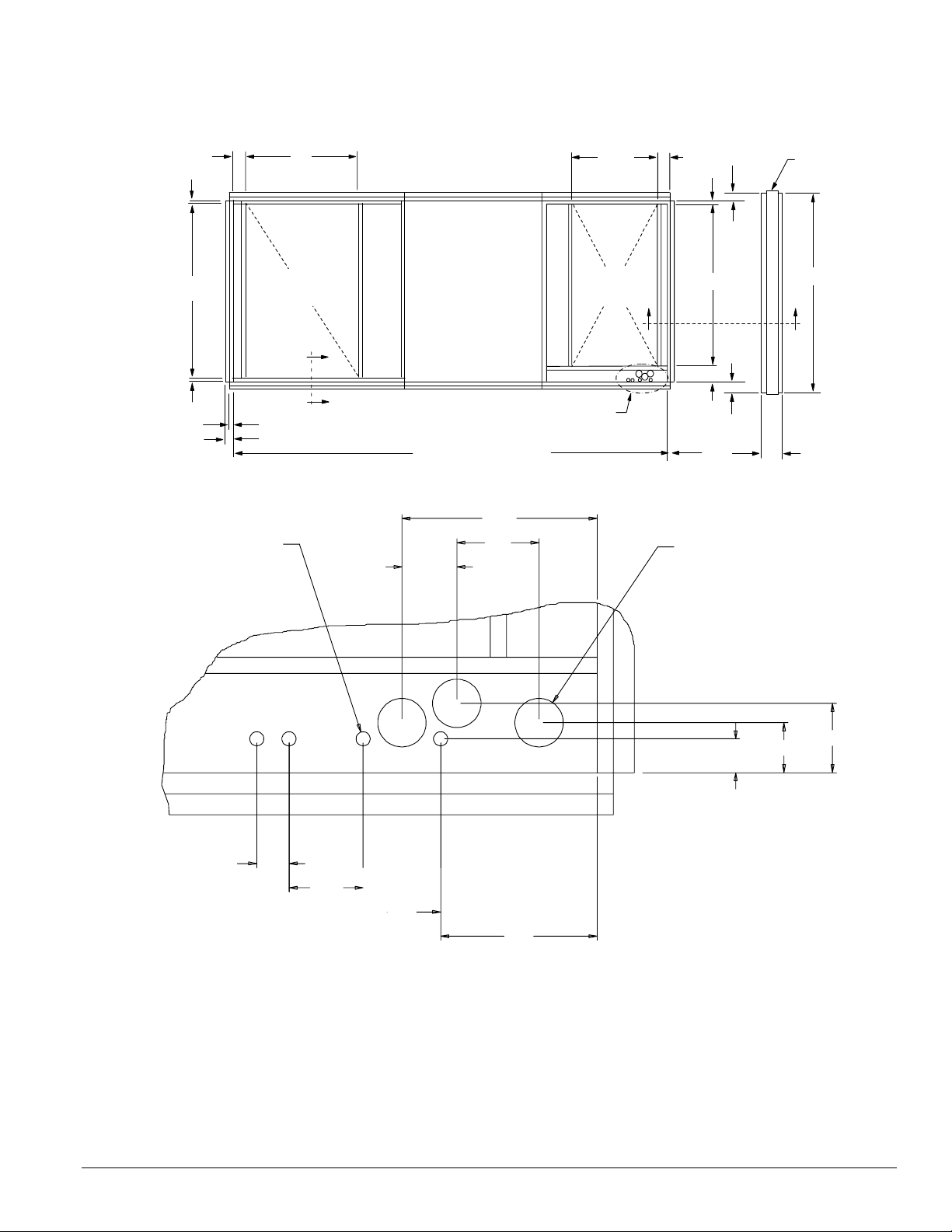
Figure 3. Typical component locations—RPS units
Top View
Bottom return air opening
R F S
R S
Bottom discharge air opening
Outside and return air dampersa
Power and control entrances
Side View
Exhaust
hood
Optional back
return opening
Filter section
Return air
Return airReturn air
fan
Supply air fan
Outside air
louvers
Evaporator coil
Heat section (natural gas, oil,
steam, hot water, electric
Discharge plenum
(main control panel)
Air cooled condenser
2 IM 738-2
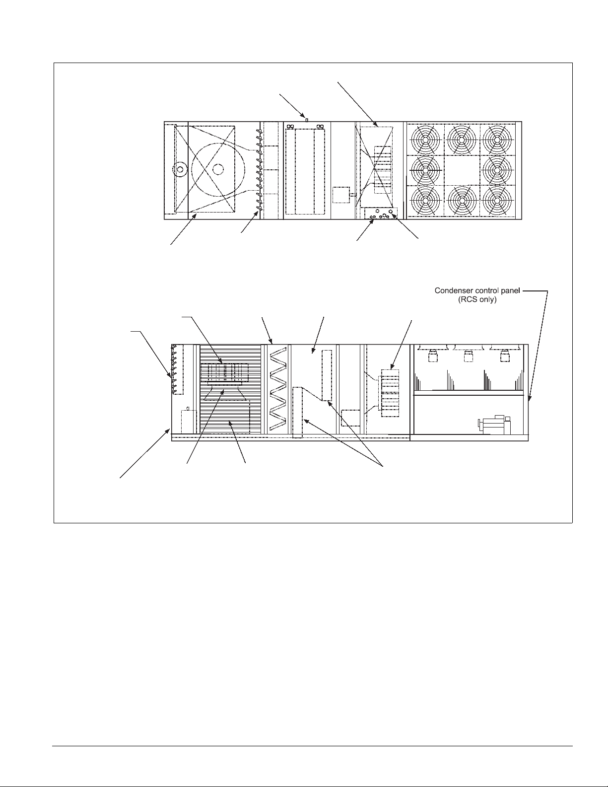
Figure 4. Component locations—RDT units
Top View
Introduction: Unit Description
Bottom supply air opening
1.50 MPT drain
Bottom return opening
Side View
Return air plenum
Exhaust dampers
Optional back return
air opening
Return air fan
Optional outside &
return air dampers
Filter section
Outside air louvers
(both sides)
Control entrances 7/8" dia K.O.
DX coil section
Evaporator coils
Power entrances 3" dia K.O.
Supply fan section
IM 738-2 3
Introduction: Condenser Fan Arrangement
Condenser Fan Arrangement
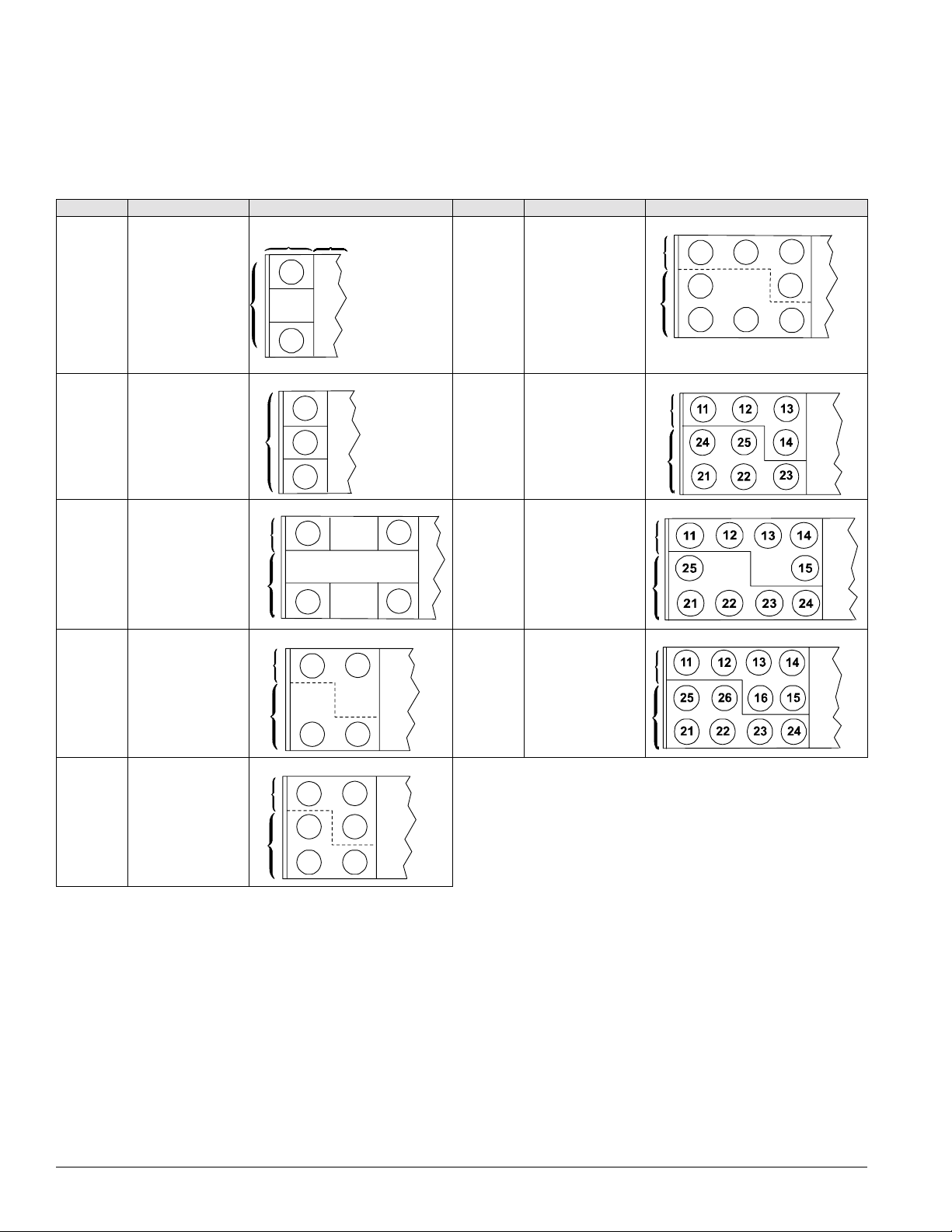
Table 2 below shows the condenser fan numbering
conventions and locations for each unit size.
Table 2: Condenser fan arrangement
Unit size Refrigerant circuit Arrangement Unit size Refrigerant circuit Arrangement
COND
015C
018C
020C
1 or 2
12
11
AHU
075C
080C
090C
1
2
11
24
21
12
22
13
14
23
025C
030C 1 or 2
1
036C
040C
045C
05
0C
060C
0C
07
2
1
2
1
2
13
12
11
11
21
11
21
11
23
21
12
12
13
22
22
12
22
105C
115
125C
5C
13
1
2
1
C
2
1
2
4 IM 738-2
Introduction: Refrigeration Piping
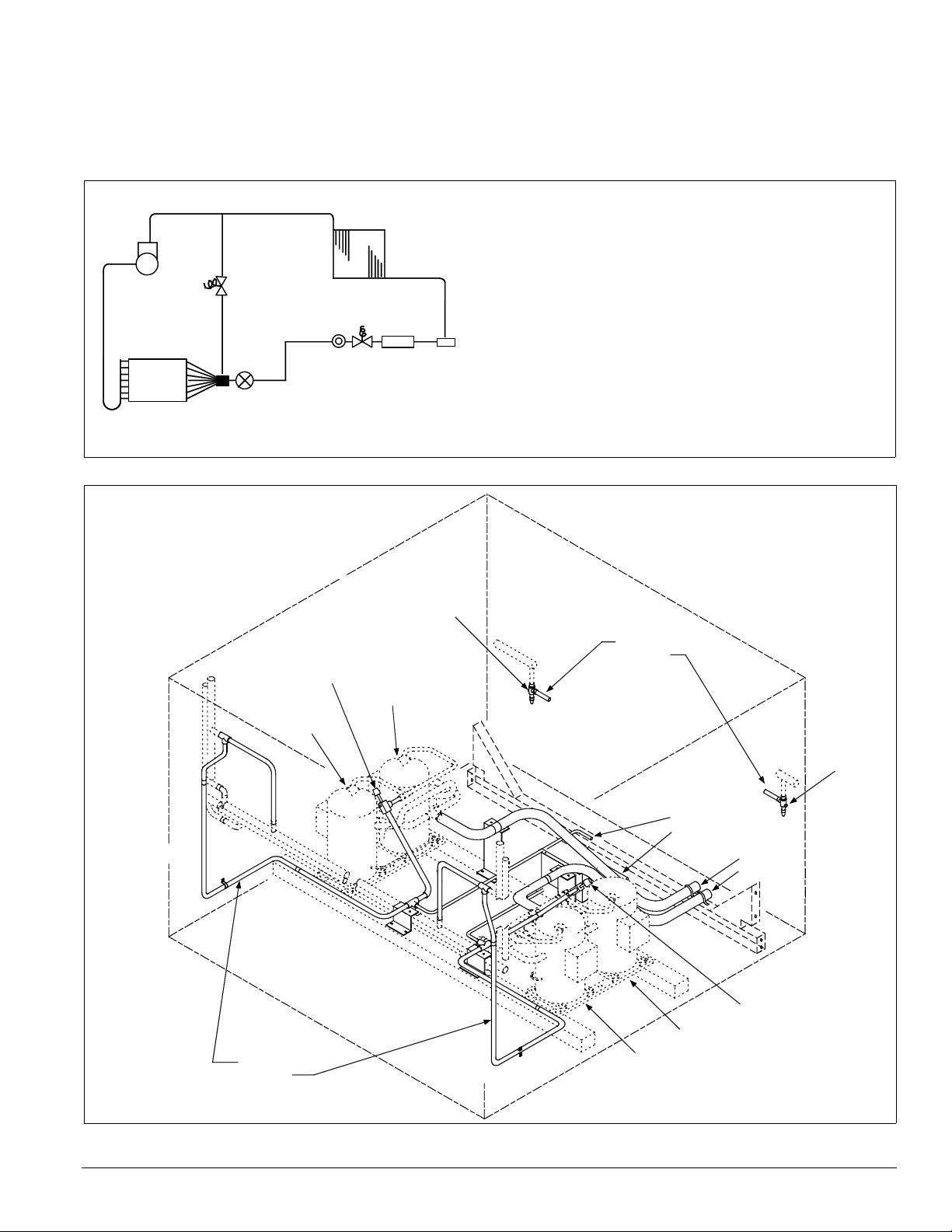
Refrigeration Piping
This section presents the unit refrigeration piping diagrams for
the various available configurations.
Figure 5. Circuit schematic
A Compressor (1, 2, or 3 per circuit)†
B Discharge line †
B
A
M
C
J
N
L
K
G
H
I
F
E
D
Figure 6. Condenser piping, scroll compressors, one to three compressors p er circuit are provided (015 to 105C)
Legend
1 - Discharge shut-off valve—Circuit #1
2 - Liquid shut-off valve—Circuit #1
3 - Liquid shut-off valve—Circuit #2
4 - Discharge shut-off valve—Circuit #2
C Condenser coil †
D Evapo rator coil*
E Manual shutoff valve†
F Filter-drier*
G Liquid line solenoid valve*
H Sightglass*
I Liquid line*†
J Suction line
K Thermal expansion valve*
L Distributor*
M Hot gas bypass and solenoid valve (optional)*†
N Hot gas bypass lines (optional)* †
*Supplied on RFS unit
pplied on RCS units
†Su
s
Compressor #1
Discharge lines
Circuit #1
Circuit #2
1
Compressor #3
2
Liquid lines
Circuit #1
Circuit #2
3
Compressor #4
Compressor #2
Optional
hot gas
bypass
lines
Circuit #1
Circuit #2
Suction
lines
Circuit #1
Circuit #2
4
IM 738-2 5
Introduction: Refrigeration Piping
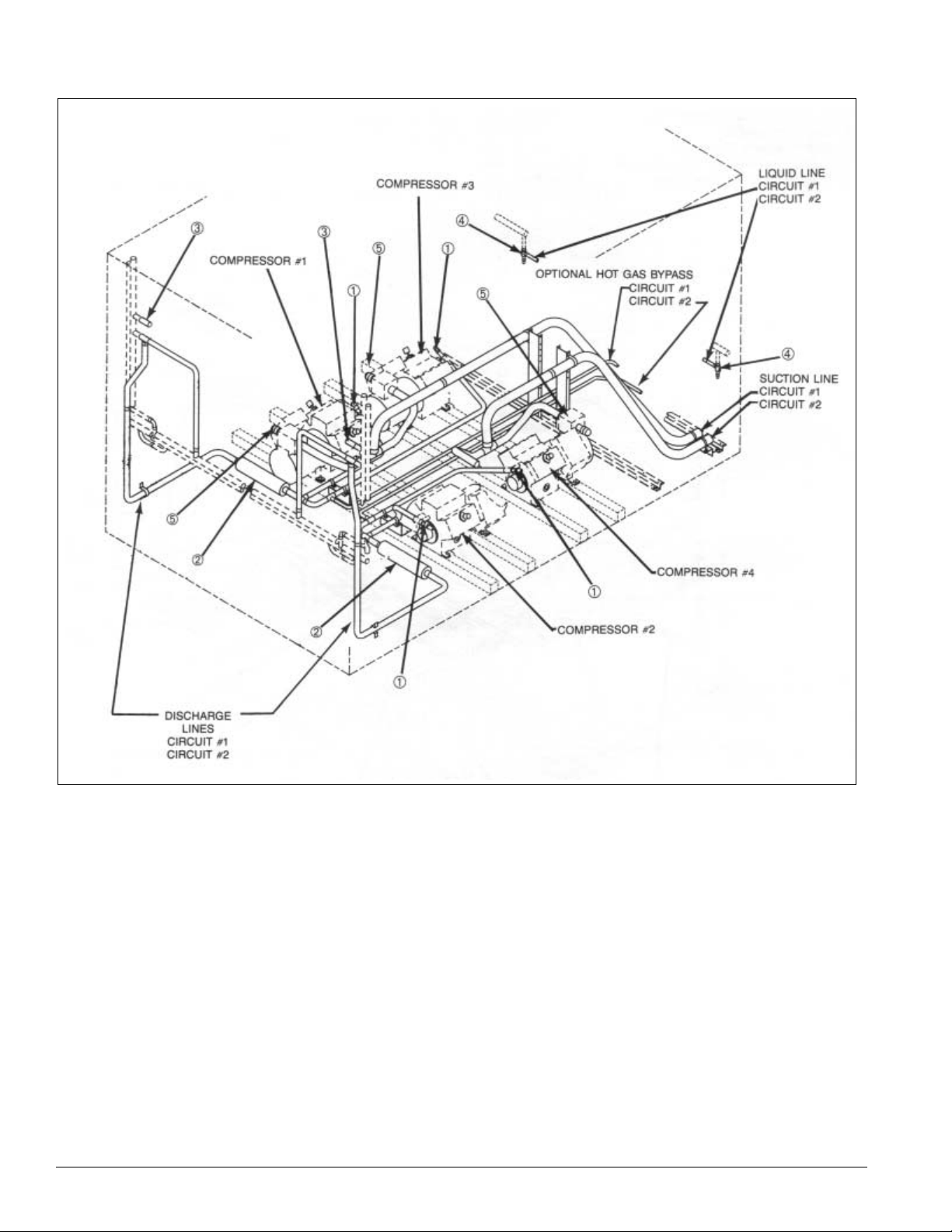
Figure 7. Condenser piping, four reciprocating compressors (115 to 135C)
Legend
1 - Discharge Line Service Valve
2 - Discharge Muffler
3 - High Pressure Relief Valve
4 - Liquid Line Manual Shut-off Valve
5 - Suction Line Service Valve
6 IM 738-2
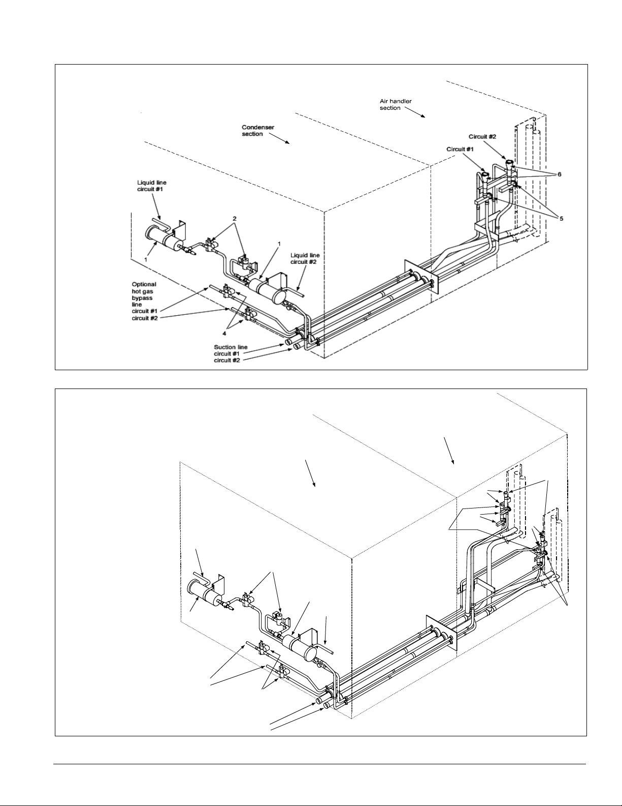
Figure 8. Air handler piping (flat DX)
circu
Legend
1 - Filter-drier
2 - Liquid line solenoid valve
3 - Sightglass
4 - Hot gas bypass
and solenoid valve (optiona l )
5 - Thermostatic
expansion valve
6 - Distributor
Introduction: Refrigeration Piping
Figure 9. Air handler piping (staggered DX)
Legend
1 - Filter-drier
2 - Liquid line solenoid valve
3 - Sightglass
4 - Hot gas bypass and solenoid valve (optional)
5 - Thermostatic expansion valve
6 - Distributor
Liquid line
circuit #1
1
Optional
hot gas
bypass
line
circuit #1
circuit #2
Air handler
section
Condenser
section
Circuit #1
6
5
Circuit #2
2
1
Liquid line
circuit #2
4
6
5
Suction line
circuit #1
it #2
IM 738-2 7
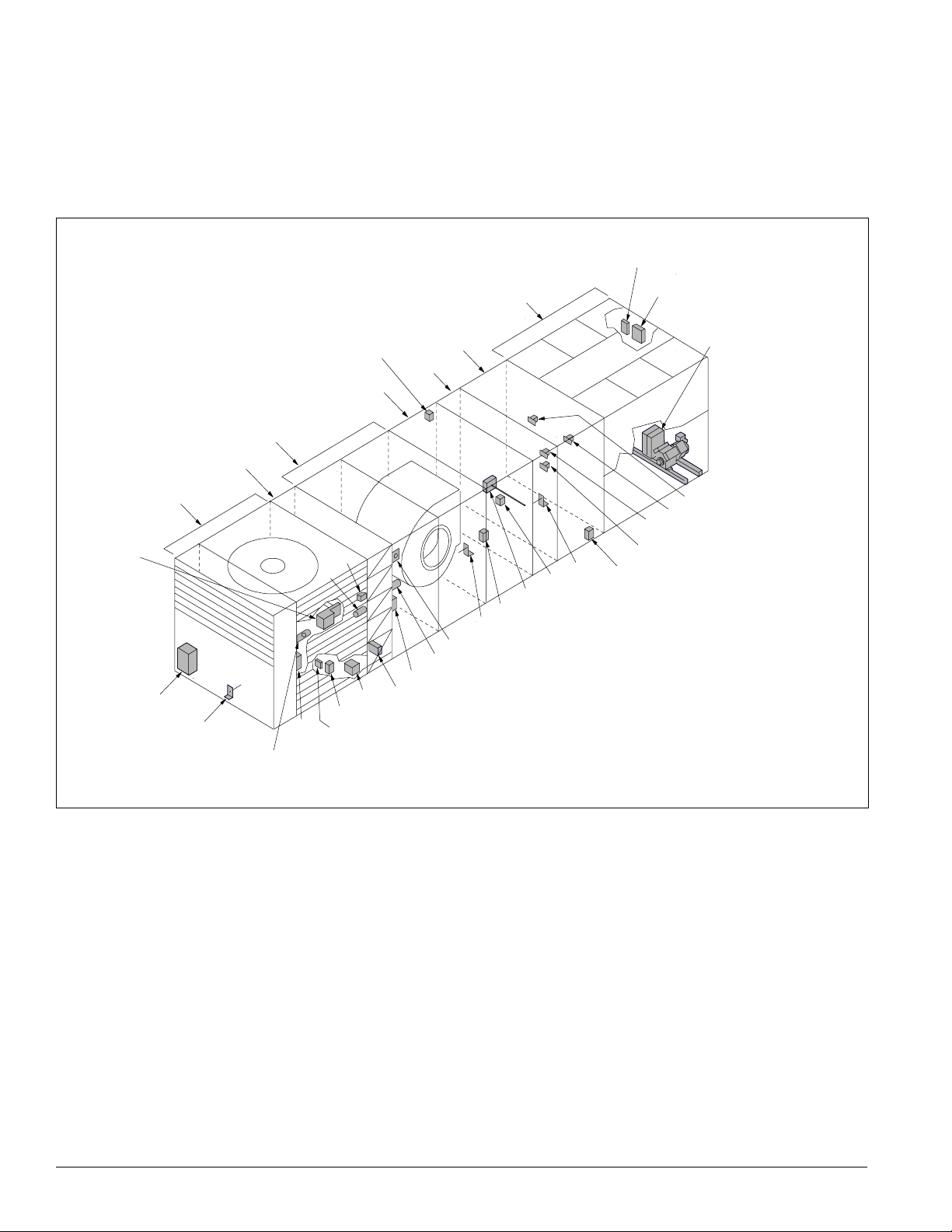
Introduction: Control Locations
Control Locations
Figure 10 (RPS Units) and Figure 11 on page 9 (RDT Units)
show the locations of the various control components mounted
hout the units. See “Control Panel” on page 10 for the
throug
locations of control components mounted in control panels.
Figure 10. Control locations—RPS units
FS1
SD2
(optional)
Return air
economizer
C19
RAT
Filter
section
Supply
fan
section
LT11
(optional)
OAT
S11,
REC11
(optional)
Heat
section
OAE
ACT3
ACT6 (optional)
RAE (optional)
section
S10, REC10
PC5
DX
LT10
ditional information is included in Table 3 on page 18 and
Ad
the wiring diagram legend, which is included in “Wiring
Diagrams” on page 62.
SC11, 12
(optional)
C11, 12
(optional)
SV1
SV5 (optional)
SV6 (optional)
ACT5 (optional)
HP1-2, HP3-4 (optional)
LP1-2
HTR1-2, HTR3-4 (optional)
SV2
Discharge
plenum
section
(optional)
HL22
(optional)
(optional)
Condensor
PC7
EFT
section
SD1
DAT
(optional)
VM1
(optional)
8 IM 738-2
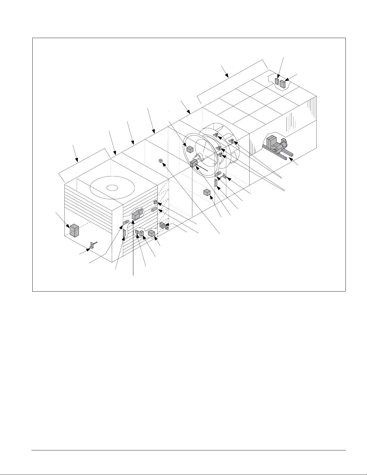
Figure 11. Control locations—RDT units
DX
section
Filter
section
Economizer
return air
Heat
section
Supply fan
discharge
plenum
section
C9
Condenser
section
Introduction: Control Locations
SC11, 21
(optional)
C11, 21
(optional)
HP1-2, LP1-2
HTR1-2, U1/U2
HP3-4 (optional)
HTR3-4 (optional)
SV1, 2
C19, 20
(optional)
RAT
LT11 (optional)
S11, REC11
SD2
(optional)
(optional)
RAE
(optional)
ACT3
ACT6
PC5
OAE
OAT
VM1
(optional)
FS1
(optional)
DAT
LT10 (optional)
S10, REC10 (optional)
SD1 (optional)
SV5, 6 (optional)
IM 738-2 9
Introduction: Control Panel
Control Panel
The unit control panels and their locations are shown in the
following figures. These figures show a typical unit
configuration. Specific unit configurations may differ slightly
Figure 12. Control panel locations
Prop exhaust
(optional)
not shown)
(
VFDs, line reactors, and
manual bypass
(optional)
Electric heat
control panel
(optional)
from these figures depending on the particular unit options.
See “Wiring Diagrams” on page 62 for the legend and
component description.
Supply fan
section
Condenser
section
Main control panel
10 IM 738-2
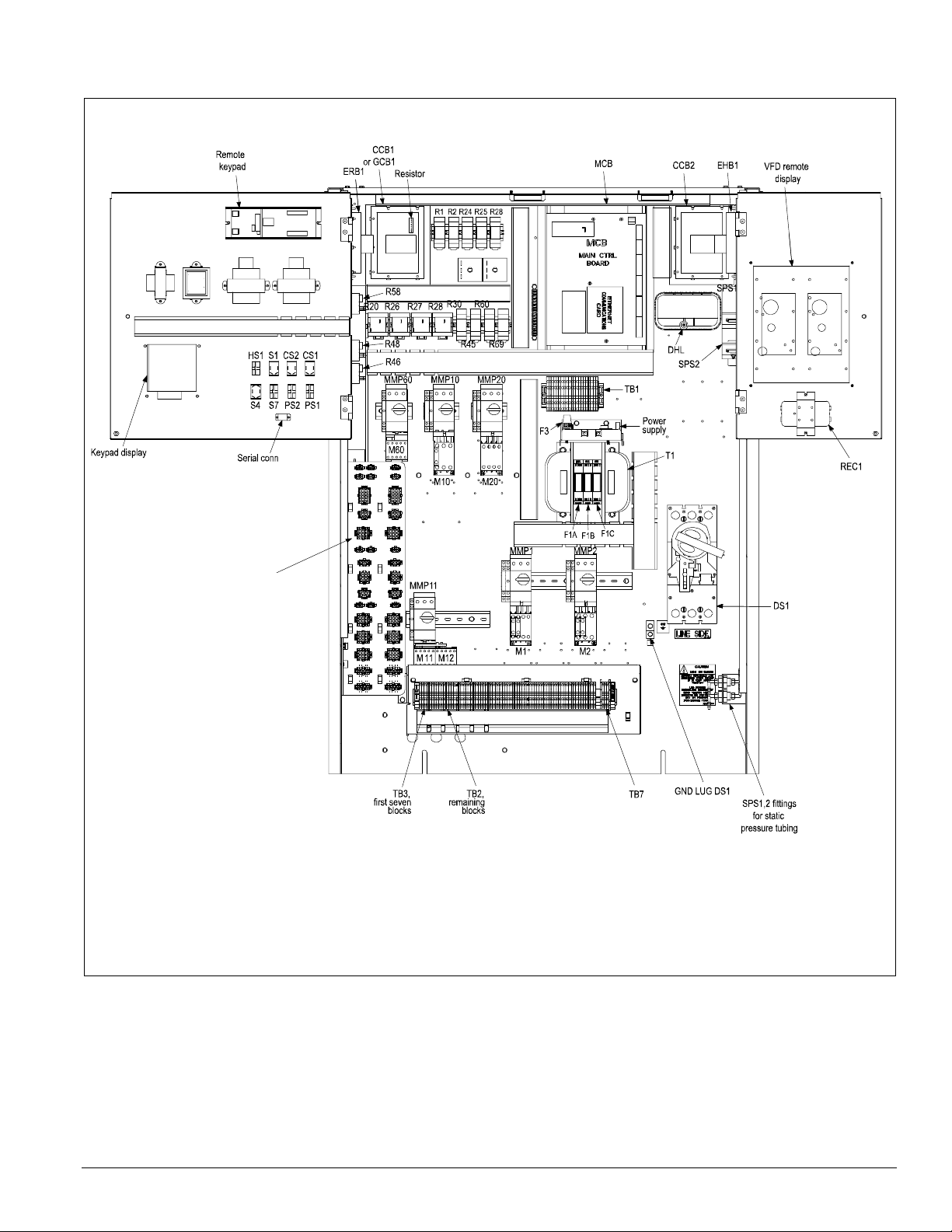
Figure 13. Typical main control panel, 015 to 040, 460 volt
Introduction: Control Panel
See separate
detail, page 17.
IM 738-2 11
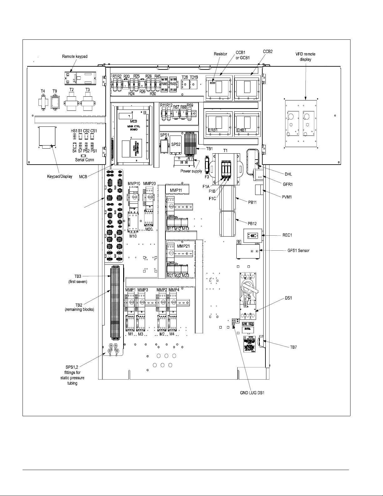
Introduction: Control Panel
Figure 14. Typical main control panel, 045 to 075, 460 volt
See separate
detail, page 17.
12 IM 738-2
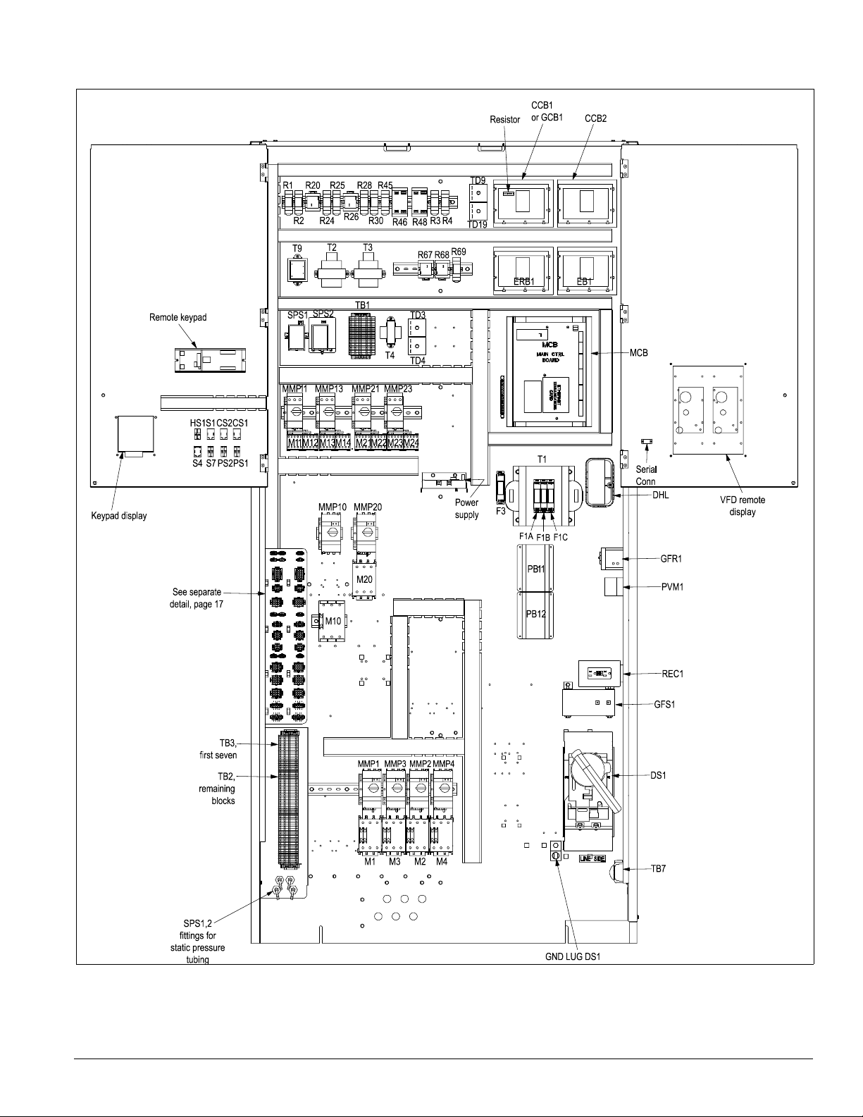
Figure 15. Typical main control panel, 080 to 135, 460 volt
Introduction: Control Panel
IM 738-2 13
Introduction: Control Panel
A
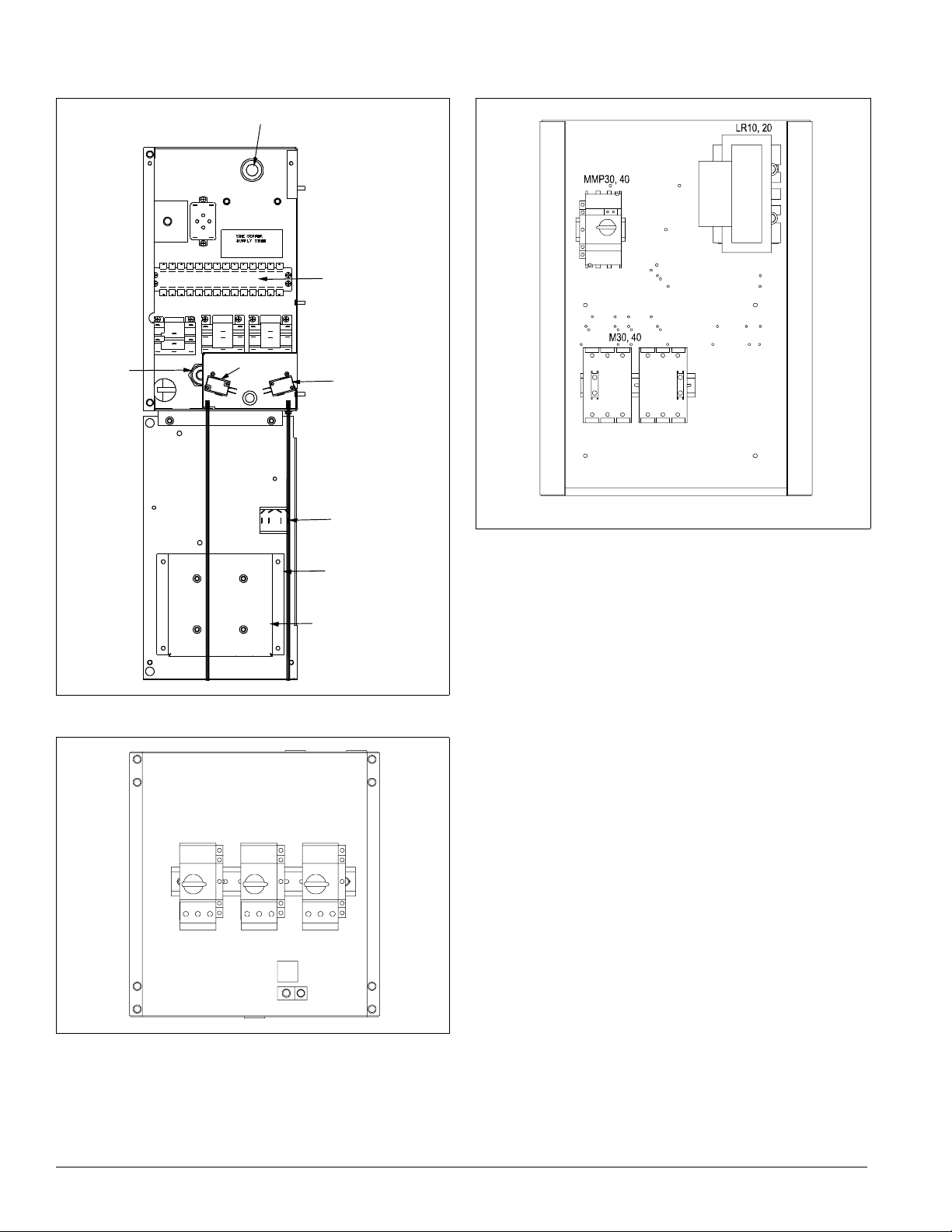
Figure 16. Typical gas heat panel, 1000 MBH
IT
R22
TD10
TB11
R20
S
R23 R21
LS2
LS1
S3
Figure 18. VFD bypass panel, 40 HP , 460 volt)
FSG
FSG Time
Figure 17. Typical propeller exhaust panel, three fans, 460
vo
lt
M51 M52 M53
AFD20 GND
14 IM 738-2
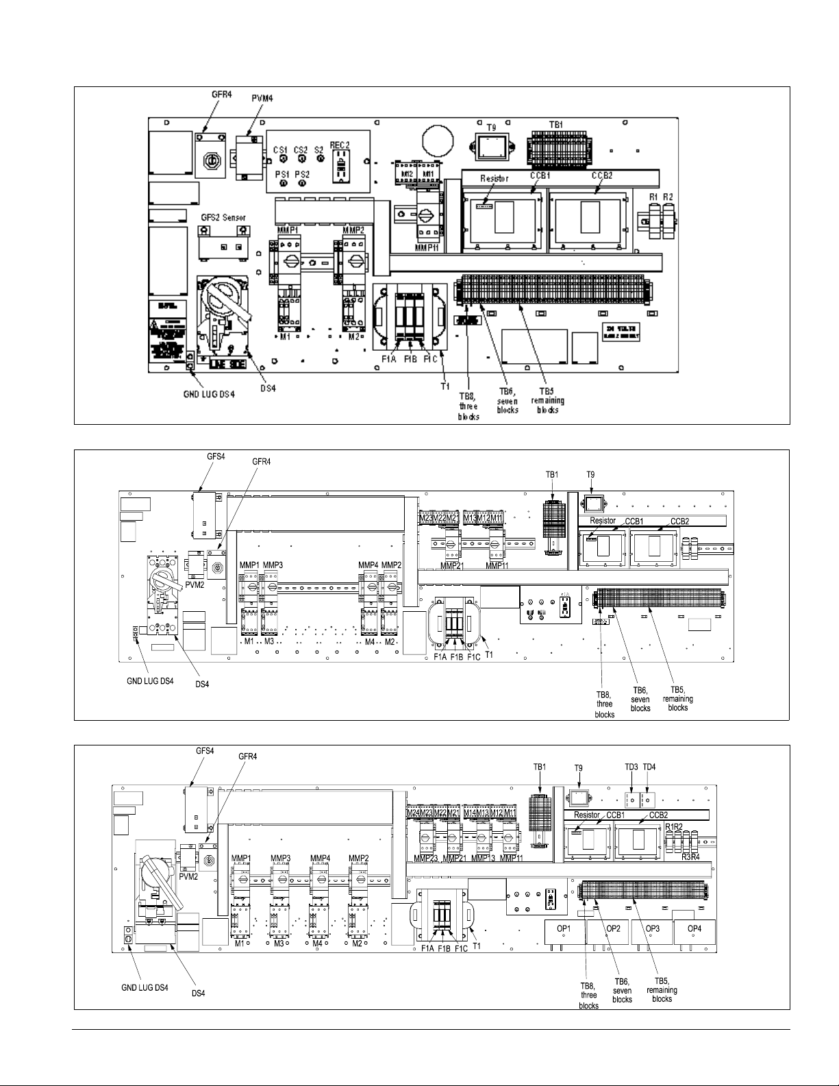
Figure 19. RCS control panel with MicroTech II, 015 to 040C
Introduction: Control Panel
Figure 20. RCS control panel with MicroTech II, RPS 045 to 075C
Figure 21. RCS control panel with MicroTech II, RPS 080 to 135C
IM 738-2 15
Introduction: Control Panel
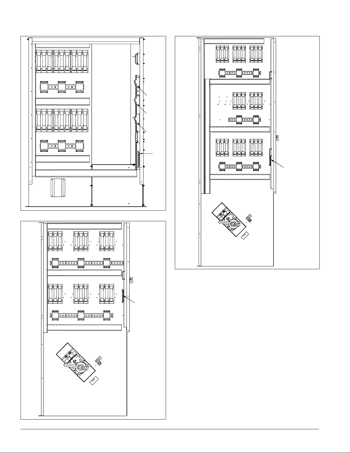
Figure 22. Electric heat panel, sizes 15 to 40C
FB33 FB32 FB31
M33 M32 M31
FB43 FB42 FB41
M41 M42 M41
SR2
SR3
SR1
TB11
Figure 24. Electric heat panel, sizes 80 to 135
FB31FB32FB33
M31M32M33
FB34FB44
M34M44
FB41FB42FB43
M41M42M43
H53
TB11
PB3
Figure 23. Electric heat panel, sizes 45 to 75C
FB31FB32FB33
M31M32M33
FB41FB42FB43
M42
M41M43
GLG3
DS3
H53
TB11
GLG3
DS3
16 IM 738-2
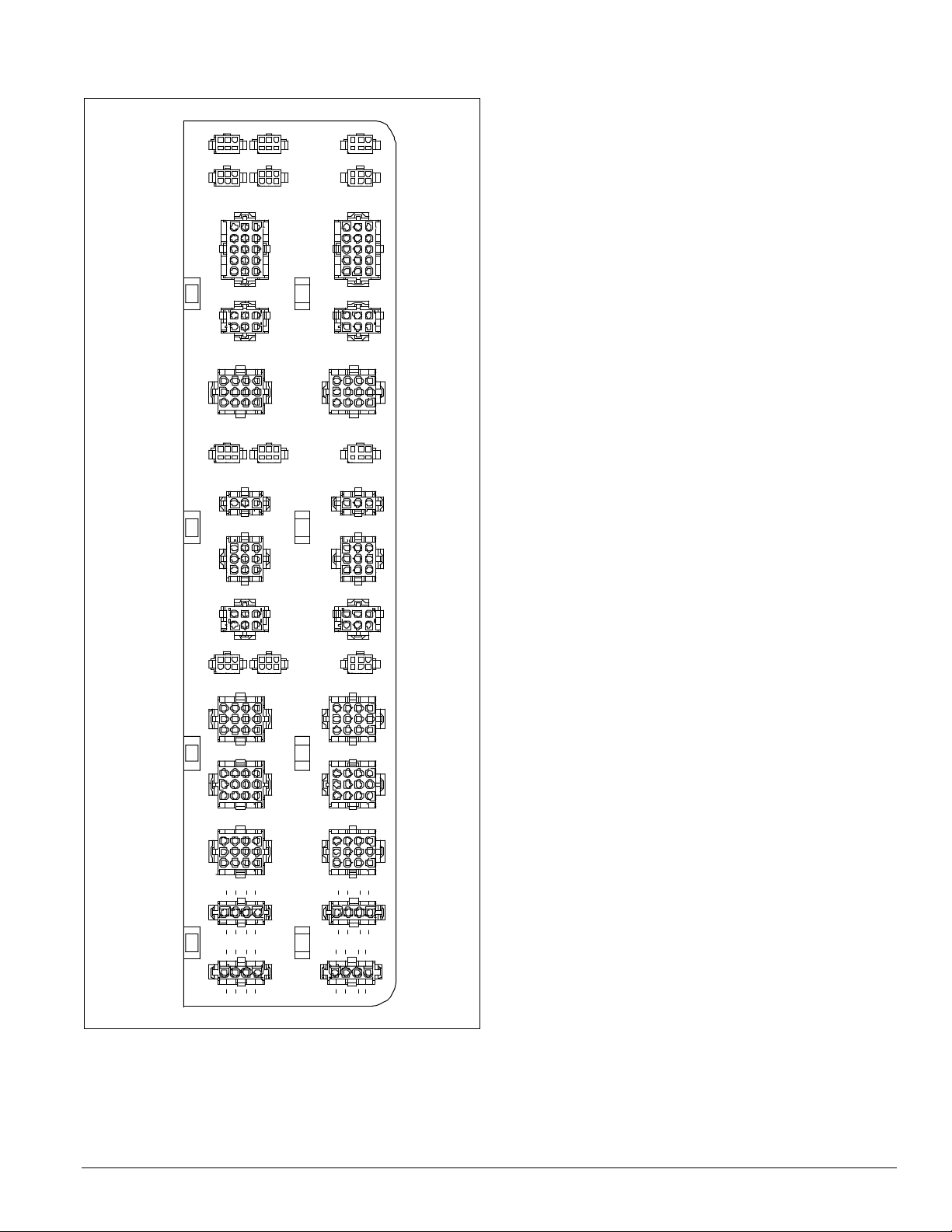
Figure 25. Harness plug connector detail
RATS OATSDATS
FP1 OPEN1EPTS
AFD10 AFD20
SV12 SV56
ACT3 OPEN2
OAE PC7PC5
Introduction: Control Panel
HL22 OPEN3
GSHT1 GSHT2
SD1 SD2
DFRH DFLH OPEN4
COMP1 COMP2
COMP3 COMP4
COMP6COMP5
LT11LT10
LT OP1 LT OP2
IM 738-2 17
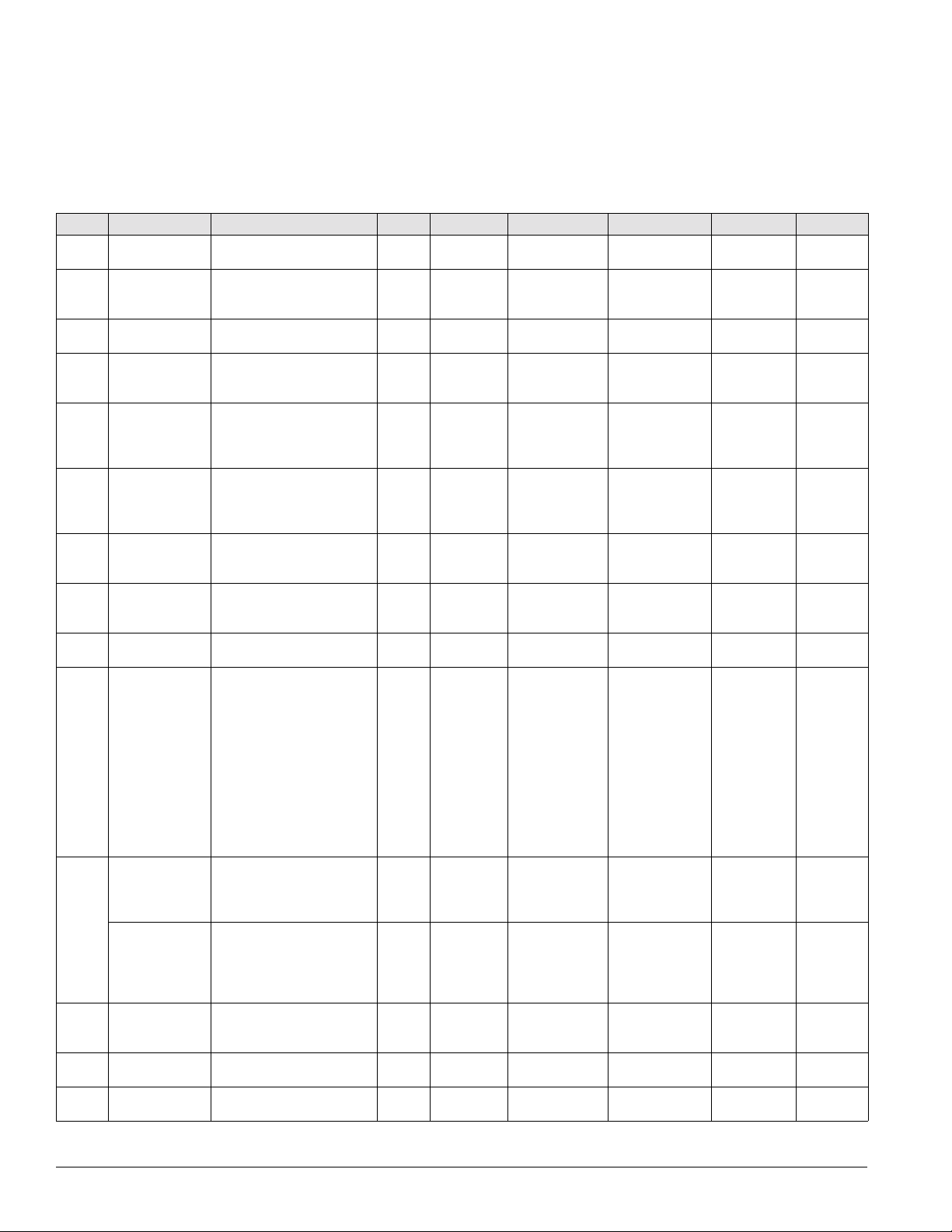
Introduction: Controls, Settings, and Functio ns
Controls, Settings, and Functions
Table 3 below lists all of the unit control devices. Included in
the table are the device symbol, a descrip
tion of the device, its
setting, any setting ranges, differentials, and the device part
number.
function, and any reset information, its location, any device
Table 3: Controls, settings, and functions
Symbol Description Function Reset Location Setting Range Differential Part no.
CS1 & 2 Switch (toggle),
HP1, 2,
MP1–6 Compressor
refrigerant circuit
DAT Discharge air
temperature
sensor
DHL Duct high limit
switch
EFT Entering fan air
temperature
sensor
FP1, 2 Evaporator frost
protection
FS1 Freezestat Shuts off fans, opens heating
High pressure
3 & 4
control
LP1, 2 Low pressure
control
MCB Main control board Processes input information N/A Main control
motor protector
OAE Enthalpy control
(electromechanical)
Enthalpy control
(electronic)
OAT Outside air
temperature
sensor
PC5 Dirty filter switch Senses filter pressure drop Auto First filter
PC6 Dirty filter switch Senses filter pressure drop Auto Final filter
Shut
s off compressor control
circuits manually
Senses discharge air
temperature
Prevents excessive VAV duct
pressures; shuts off fan
Senses entering fan air
temperature
Senses low refrigerant
temperature
valve, and closes outdoor
damper if low air temperature
at coil is detected
tops compressor when
S
refrigerant discharge pressure
is too high
Stops compressor when
suction pressure is too low
(used for pumpdown)
Senses motor winding
temperature, shuts off
compressor on high
temperature.
Notes:
1.Unit size 018C compressors
include internal moto
pr
otector.
2.Unit sizes 020C–036
circuit #1
internal motor protector (r ef er
to unit wiring diagram)
Returns outside air dampers to
minimum position when
enthalpy is too high
Returns outside air dampers to
minimum position when
outside air enthalpy is higher
than return air empalthy
(use RAE)
Senses outside air
temperature
compressors include
r
C,
.
N/A Main control
N/A Discharge air
Auto Main control
N/A Inlet of supply
N/A Return bends
Auto Heating
Manual
(relay
latched)
Auto Compressor See page 117. N/A 25 psi
Auto at
3400
ohms
Auto Economizer
Auto Economizer
N/A N/A N/A 060004705
panel
section
panel
fan
of
evaporative
coil
section
Compressor See page 117. N/A 100 psi
box
Compressor
junction box
section
section
section
section
N/A N/A N/A 01355000
N/A N/A 060004705
3.5" w.c
(871.8 Pa)
N/A N/A 060004705
Opens at 30°F
Closes at 45°F
38°F (3°C)
or as required
N/A N/A N/A 060006101
9 K–18 K ohms 700 ohms cold N/A 044691509
“B” or as required A–D Temperature:
Fully CW past “D”
(when used
with RAE)
As required .05-5" w.c.
As required .05-5" w.c.
0.05–5.0" w.c.
(12.5–1245.4 Pa)
N/A N/A 072501901
35°F–45°F
(2°C–7°C)
A–D N/A 049262201
(12.5–1245.4 Pa)
(12.5–1245.4 Pa)
.05" w.c.
(12.5 Pa), fixed
12°F (7°C),
fixed
(689 kPa)
(172 kPa)
3.5°F (2°C)
Humidity:
5% fixed
.05" w.c.
(12.5 Pa)
.05" w.c.
(12.5 Pa)
065493801
065830001
047356120
047356111
030706702
065493801
065493801
18 IM 738-2
Introduction: Controls, Settings, and Functio ns
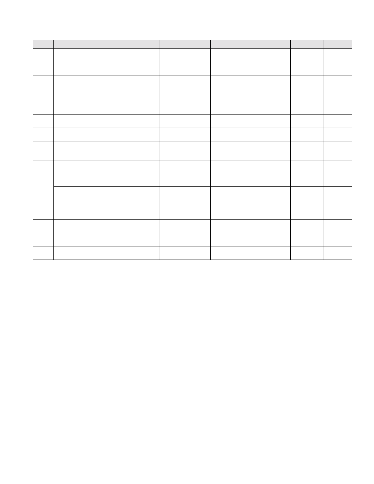
Table 3: Controls, settings, and functions (continued)
Symbol Description Function Reset Location Setting Range Differential Part no.
PC7 A i r flow proving
switch
PS1, 2 Pumpdown switch Used to manually pump down
RAE Return air
enthalpy sensor
RAT Return air
temperature
sensor
SD1 Smoke detector,
supply air
SD2 Smoke detector,
return air
SPS1 Static pressure
sensor duct #1
SPS2 Static pressure
sensor duct #2
Static pr essure
sensor: building
(space) pressure
SV1, 2
Solenoid valve
(liquid line)
Solenoid valve
SV5, 6
(hot gas bypass)
System switch
S1
S7 ON-OFF-AUTO
switch
Senses supply fan pressure to
prove airflow
compressor
Used to compare return air
enthalpy to outside air
enthalpy (used with OAE)
Senses return air temperature N/A Return air
Initiates unit shutdown if
smoke is detected
Initiates unit shutdown if
smoke is detected
Converts static pressure
signals to voltage signals
Converts static pressure
signals to voltage signals and
sends them to MicroTech II
controller
Converts static pressure
signals to voltage signals.
Closes liquid line for
pumpdown
Closes hot gas bypass line for
pump-down
Shuts off entire control circuit
(except crankcase heaters)
Used to manually switch unit N/A Main control
Auto Supply fan
section
N/A Condenser
control box
N/A Economizer
section
section
Manual Discharge air
section
Manual Return air
section
N/A Main control
box
N/A Main control
box
N/A Main control
box
N/A Condenser
section
N/A Condenser
section
N/A Main control
box
box
.10" w.c. (25 Pa) .05-5" w.c.
N/A N/A N/A 01355000
N/A N/A N/A 049262202
N/A N/A 060004705
N/A N/A N/A 04925001
N/A N/A N/A 04925001
N/A 0–5" w.c.
N/A 0–5" w.c.
N/A -025–0.25" w.c.
N/A N/A N/A See parts
N/A N/A N/A 111011001
N/A N/A N/A 001355000
N/A N/A N/A
(12.5–1245.4 Pa)
(0–1245.4 Pa)
1–6 VDC out
(0–1245.4 Pa)
1–6 VDC out
(-62.3–62.3 Pa
VDC out
1–5
.05" w.c.
(12.5 Pa), fixed
N/A 049545007
N/A 049545007
N/A 049545006
)
060015801
catalog
IM 738-2 19
Introduction: Controls, Settings, and Functio ns
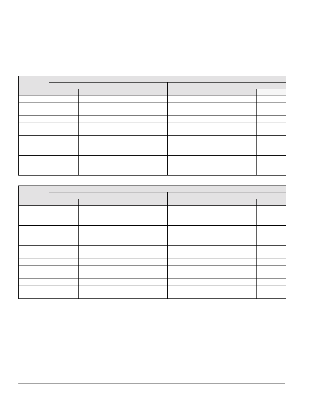
FanTrol
The FanTrol, provided on all units, is a method of head
pressure
control that automatically cycles the condenser fans
in response to ambient air temperature. This feature maintains
head pressure and allows the unit to run at low ambient air
temperatures.
Table 4: R-22 FanTrol setpoints in °F with MicroTech II controls
RPS RCS
RDT RPR
Setpoint Differential Setpoint Differential Setpoint Differential Setpoint Differential
015 to 020C0 5605 ————
025 to 030C0 5655 ————
0360 5705 ————
045 to 045C0 5655 ————
0500 5605 ————
0600 5255705——
0700 5405705——
075 to 090C 0 5 65 5 75 5 0 5
1050505585705
1150505555755
1250 5655355805
1350 5555255655
B05 B06 B07 B08
RPS/RDT and RCS units have two independent refrigerant
s with one to four condenser fans being controlled
circuit
independently by the ambient air temperature of each circuit.
See the following sections for sequence of operation for
condenser fans with FanTrol.
Degrees Farenheit
Table 5: R-407C FanTrol setpoints in °F with MicroTech II controls
Degrees Farenheit
RPS, RCS, RDT
Setpoint Differential Setpoint Differential Setpoint Differential Setpoint Differential
015 0 5 60 5
018 to 020C0505————
025 to 036C0 5655 ————
040 0 5 60 6
0450 5555 ————
050 0 5 50 5 — —
0600 5155705——
0700 5305705——
0750 5655755 0 5
080 to 090C 0 5 65 5 75 5 0 5
1050505525705
1150505455755
1250 5555305805
1350 5455205655
B05 B06 B07 B08
20 IM 738-2
Mechanical Installation
Mechanical Installation: Receiving Inspection
The installation of this equipment shall be in accordance with
the regulations of authorities having jurisdiction and all
applicable codes. It is the responsibility of the installer to
determine and follow the applicable codes.
Note: Low head pressure may lead to poor, erratic refrigerant
feed control at the thermostatic expansion valve. The
units have automatic control of the condenser fans
which should provide adequate head pressure control
down to 50°F (10°C) provided the unit is not exposed to
windy conditions. The system designer is responsible
for assuring the condensing section is not exposed to
excessive wind or air recirculation.
CAUTION
Sharp edges on sheet metal and fasteners can c ause
personal injury.
This equipment must be installed, opera
only by an experienced installation company and fully
trained personnel.
Figure 26. Service clearances
ted, and serviced
Receiving Inspection
When the equipment is received
, all items s
hould be carefully
checked against the bill of lading to be sure all crates and
cartons have been received. If the unit has become dirty
during shipment (winter road chemicals are of particular
concern), clean it when received.
All units should be carefully
inspected for damage when
received. Report all shipping damage to the carrier and file a
claim. In most cases, equipment is shipped F.O.B. factory and
claims for freight damage should be filed by the consignee.
Before unloading the unit, check the unit nameplate to make
the voltage complies with the power supply available.
sure
Unit Clearances
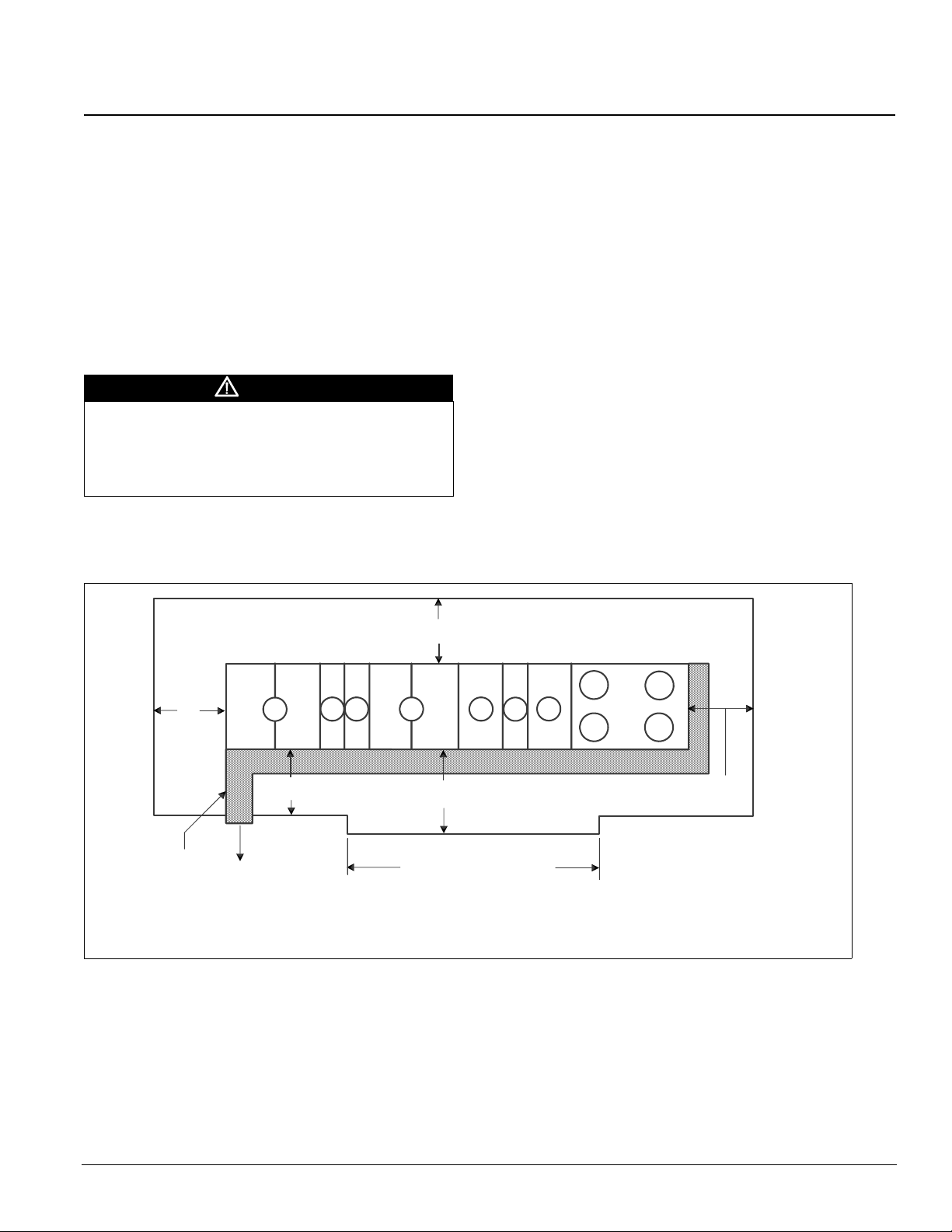
Service Clearance
Allow service clearance approximately as indicated in Figure
26. Also, Daikin recommends providing a roof walkway to
the rooftop unit as well as along at least the two sides of the
unit that provide access to most controls and serviceable
components.
60"
(1524 mm)
Roof walkway
To roof
access
location
A
60"
(1524 mm)
BC
72"
(1829 mm)
DE
96"
(2438 mm)
Varies with unit arrangement
Refer to certified drawing & note.
C
F
60"
(1524 mm)
Legend:
A = Return air section
B = Filter section
C = Cooling section
D = Cooling/supply fan section
E = Heat section
F = Discharge plenum section
IM 738-2 21
Mechanical Installation: Ventilation Clearance
V entilation Clearance
Below are minimum ventilation clearance recommendations.
The system designer must consider each application and
provide adequate ventilation. If this is not done, the unit will
not perform properly.
Unit(s) surrounded by a screen or a fence:
The bottom of the screen or fence should be at least 1 ft.
1
(305 mm) above the roof surface.
2 The distance between the unit and a screen or fence should
be as described in “Service Clearance” on page 21. See also
Figure 26 on page 21.
3 The distance between any two units within a screen or
fence should be at least 120" (3048 mm).
Unit(s) surrounded by solid walls:
1 If there are walls on one or two adjacent sides of the unit,
the walls may be any height. If there are walls on more than
two adjacent sides of the unit, the walls should not be
higher than the unit.
2 The distance between the unit and the wall should be at
least 96" (2438 mm) on all sides of the unit.
3 The distance between any two units within the walls should
be at least 120" (3048 mm).
Do not locate outside air intakes near exhaust vents or other
sources
of contaminated air.
If the unit is installed where windy conditions are common,
in
stall wind screens around the unit, maintaining the
clearances specified (see Figure 27). This is particularly
important to prevent blowing snow from entering outside air
take and to maintain adequate head pressure control when
in
mechanical cooling is required at low outdoor air
temperatures.
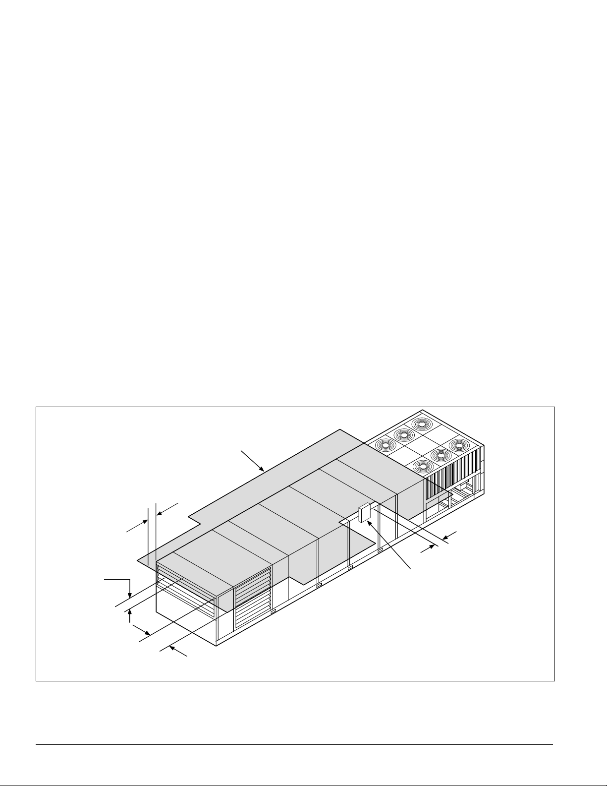
Overhead Clearance
1 Unit(s) surrounded by screens or solid walls must have no
overhead obstructions over any part of the unit.
2 The area above the condenser must be unobstructed in all
installations to allow vertical air discharge.
3 The following restrictions must be observed for overhead
obstructions above the air handler section (see Figure 27):
a There must be no overhead obstructions above the
furnace flue, or within 9" (229 mm) of the flue box.
b Overhead obstructions must be no less than 96"
(2438 mm) above the top of the unit.
c There must be no overhead obstructions in the areas
above the outside air and exhaust dampers that are
farther than 24" (610 mm) from the side of the unit.
Figure 27. Overhead clearance
24" (610 mm)
maximum
96" (2438 mm)
minimum,
top of unit to
permanent
overhead
obstruction
Overhead
canopy
9" (229 mm)
minimum to flue box,
typical all sides
Flue box
24" (610 mm)
maximum
22 IM 738-2
Roof Curb Assembly and Installation
Mechanical Installation: Roof Curb Assembly and Installation
Locate the roof curb and unit on a portion of the roof that can
support the weight of the unit. The unit must be supported to
prevent bending or twisting of the machine.
If building construction allows sound and vibration into the
occupied s
pace, locate the unit over a non-critical area. It is
the responsibility of the system designer to make adequate
provisions for noise and vibration in the occupied space.
WARNING
Mold can cause personal injury. Some materials such as
gypsum wall board can promote mold growth when damp.
Such materials must be protected from moisture that can enter
units during maintenance or normal operation.
Install the curb and unit level to
allow the condensate drain to
flow properly and allow service access doors to open and close
without binding.
Integral supply and return air duct flanges are provided with
the RPS/
RFS roof curb, allowing connection of duct work to
the curb before the unit is set. The gasketed top surface of the
duct flanges seals against the unit when it is set on the curb.
These flanges must not support the total weight of the duct
work. See “Installing Ductwork” on page 49 for details on duct
connections. It is critical that the con
densate drain side of the
unit be no higher than the opposite side.
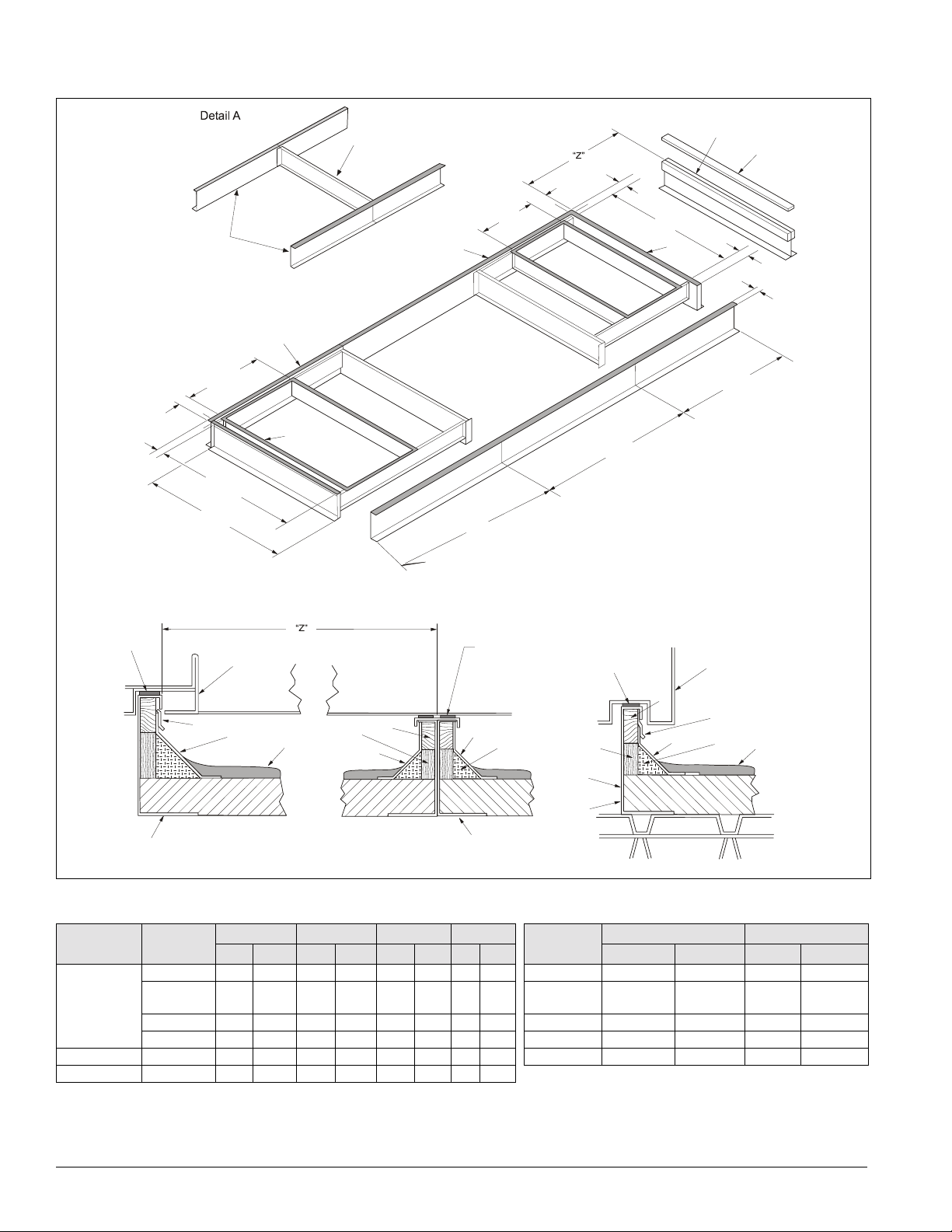
Assembly of a typical RPS/RDT roof curb is shown in
Figure 29 on page 24. Parts A through K are common to all
units having bottom return openings. Depending on the unit
th, Parts L and M may be included with the roof curb kit to
leng
create the correct overall curb length. Figure 28 shows the
assembly of the RCS roof curb.
RPS/RDT Assembly instructions (Figure 29 on
page 24)
1 Set curbing parts A through K per dimensions shown over
roof opening or on a level surface. Note location of return
and supply air openings.
2 If applicable, set other curbing parts (D, L, M, etc.) in place
making sure that the orientation complies with the
assembly instructions. Check alignment of all mating bolt
holes. See Detail A.
3 Bolt curbing parts together using fasteners provided.
Tighten all bolts finger tight.
4 Square entire curbing assembly and securely tighten all
bolts.
5 Position curb assembly over roof openings. Curb must be
level from side to side and over its length. Check that top
surface of the curb is flat with no bowing or sagging.
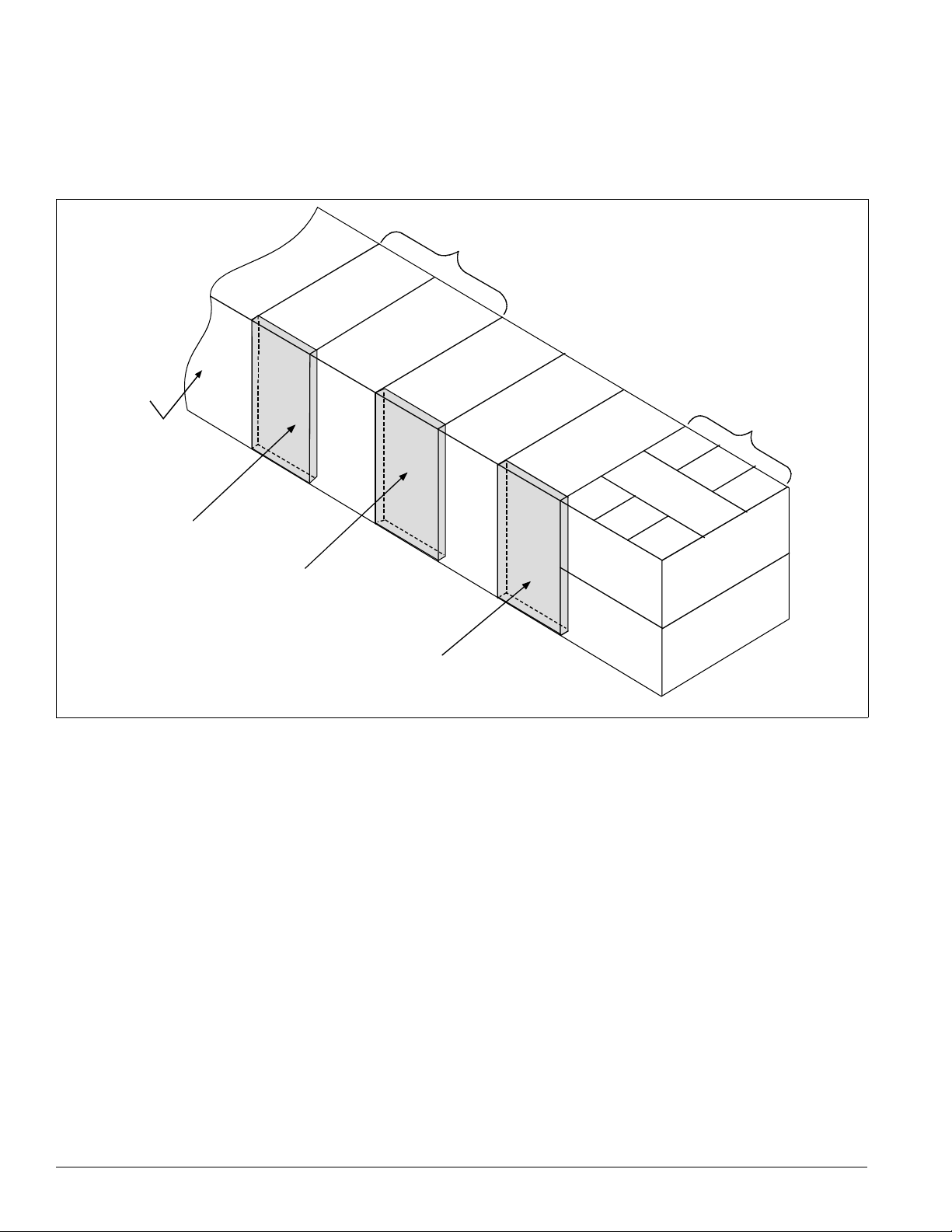
6 W eld curbing in place. Caulk all seams watertight. Remove
backing from 0.25" (6 mm) thick × 1.50" (38 mm) wide
gasketing and
7 Flash curbing into roof as shown in Detail B.
8 Parts E and F are not required on units with no return shaft
apply to surfaces shown by cross-hatching.
within the curb perimeter.
9 Parts G and H are not required on units with no supply shaft
within the curb perimeter.
10 Be sure that electrical connections are coordinated (see
Figure 30).
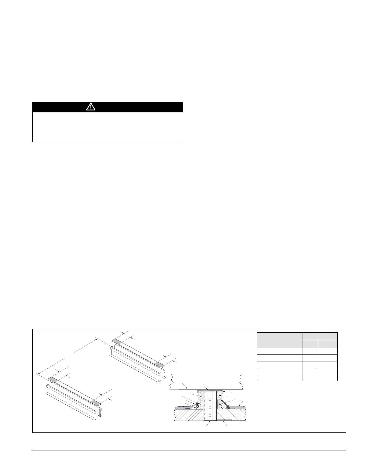
RCS Assembly instructions (Figure 28)
1 Set curbing parts (A) in place making sure that the
orientation complies with the assembly instructions. Check
alignment of all mating bolt holes.
2 Bolt curbing parts together using fasteners provided.
3 Curb must be level from side to side and over its length.
4 Weld curbing in place. Caulk all seams watertight and
insulate between channels.
5 Flash curbing into roof as shown in Detail C.
Figure 28. RCS roof curb assembly
6 "
" Z Z "
6 "
B
A
A
4 . x 4 N a i l e r S t r i p
6 "
6 . a n t S t r i p ( n o t f u r n i s h e d )
8 . u r b G a s k e t i n g
9 . I n s u l a t i o n b e t w e e n
G a l v a n i z e d u r b ( n o t f u r n i s h e d )
B
A
A
. U n i t B a s e
. G a l v a n i z e d u r b
. G a l v a n i z e d u i r b o v e r
. R i g i d I n s u l a t i o n ( n o t f u r n i s h e d )
. F l a s h i n g ( n o t f u r n i s h e d )
0 . R o o f i n g M a t e r i a l ( n o t f u r n i s h e d )
6 "
D e t a i
8
4
6
9
4
0
RCS unit size
015C–030C 31.0 787
036C & 040C 94.0 2057
045C–060C 62.0 1575
070C–105C 100.0 2540
115C–135C 120.0 3048
ZZ
in. mm
IM 738-2 23
Mechanical Installation: Roof Curb Assembly and Installation
Figure 29. RPS/RFS roof curb assembly
Using remaining side supports
in this area, align lengths on
opposite sides of assembly
M
and install a cross support
“D” at each side.
2
“Y”
Equal Length
Side Supports
“X”
8
Inside
“Y”
Inside
85"
L
“X”
E
A
1
9
B
F
Detail B
6
D
L
Return
Air
M
D
F
E
3
7
9
B
C
62.8"
Condenser
section
support
(RPS only)
9
“W”
inside
5
Condenser
Section Support
K
1.5"
6.8"
76"
G
Supply
H
Air
D
See Detail “A”
Inside
H
A
G
C
38.8"
1. Unit Base
2. Curb Gasketing
3. 2 x 4 Nailer Strip
4. Galvanized Curb
5. Cant Strip (not furnished)
6. Roofing Material (not furnished)
7. Rigid Insulation (not furnished)
8. Counterflashing (not furnished)
9. Flashing (not furnished)
7.5"
2"
Detail C
2
3
7
4
1
8
9
5
6
Main
unit curb
4
Height of perimeter curb and
Note:
condensing section support are not equal.
4
Table 6: Roof curb assembly dimensionsRPS/RFS dimensions
Unit size Fan
X Y XX YY
in mm in mm in mm in mm in mm in mm
Unit size
015–040C None 24.0 610 82.0 2083 6.8 173 1.5 38 015C–030C 45.9 1165 20.0 508
(2)15” FC 24.0 610 82.0 2083 6.8 173 1.5 38 036C and
040C
30" AF 30.0 762 76.0 1930 6.8 173 4.5 114 045C–075C 77.0 1956 28.0 712
40" AF 36.0 914 78.0 1981 14.8 376 3.5 89 80C–90C 113 2870 38.0 965
045C–075C All units 38.0 965 87.0 2210 8.8 222 3.5 89 105C—135C 113 2870 46.0 1168
80C–135C All units 62.0 1575 87.0 2210 8.8 222 3.5 89
Note: These dimensions do not apply to units with energy recovery wheels.
Z W
94.0 2388 20.0 508
24 IM 738-2
Mechanical Installation: Roof Curb Assembly and Installation
Figure 30. Typical power wire entrance, curb view (RPS/RFS 015C to 040C shown, see project certified drawings)
D
B
D
Detail A
C
2Typ
4Typ
0.9 Dia.
K.O.
A
RA
OPNG
A
A
See Detail A
Unit length minus 6.4
12.1
5.1
3.4
20.0
SA
OPNG
6.0
6.8
1.5
76.0
B
7.5
6.0
E
3.0 Dia.
K.O.
RPS only
97.0
B
8.0
4.3
2.0
4.6
4.8
9.7
2.1
3.1
IM 738-2 25
Mechanical Installation: Post and Rail Mounting
Post and Rail Mounting
When mounting by post and rail, run the structural support the
full length of the unit. Locate the structural member at the base
of the unit as shown in Figure 31, assuring the I-beam is well
supported by the structural member.
CAUTION
The unit must be level side to side
and over the entire length.
Equipment damage can result if the unit is not level.
If resilient material is placed between the unit and the
rail,
insert a heavy steel plate between the unit and the resilient
material to distribute the load. Seal cabinet penetrations
(electrical, piping, etc.) properly to protect against moisture
and weather.
Figure 31. Post and rail mounting
W
" *
3 Provide proper drainage around the unit to prevent flooding
of the equipment.
4 Provide adequate protection from vandalism, mechanical
contact, etc.
5 Securely close the doors.
6 If there are isolation dampers, make sure they are properly
installed and fully closed to prevent the entry of animals
and debris through the supply and return air openings.
7 Cover the supply and return air openings on units without
isolation dampers.
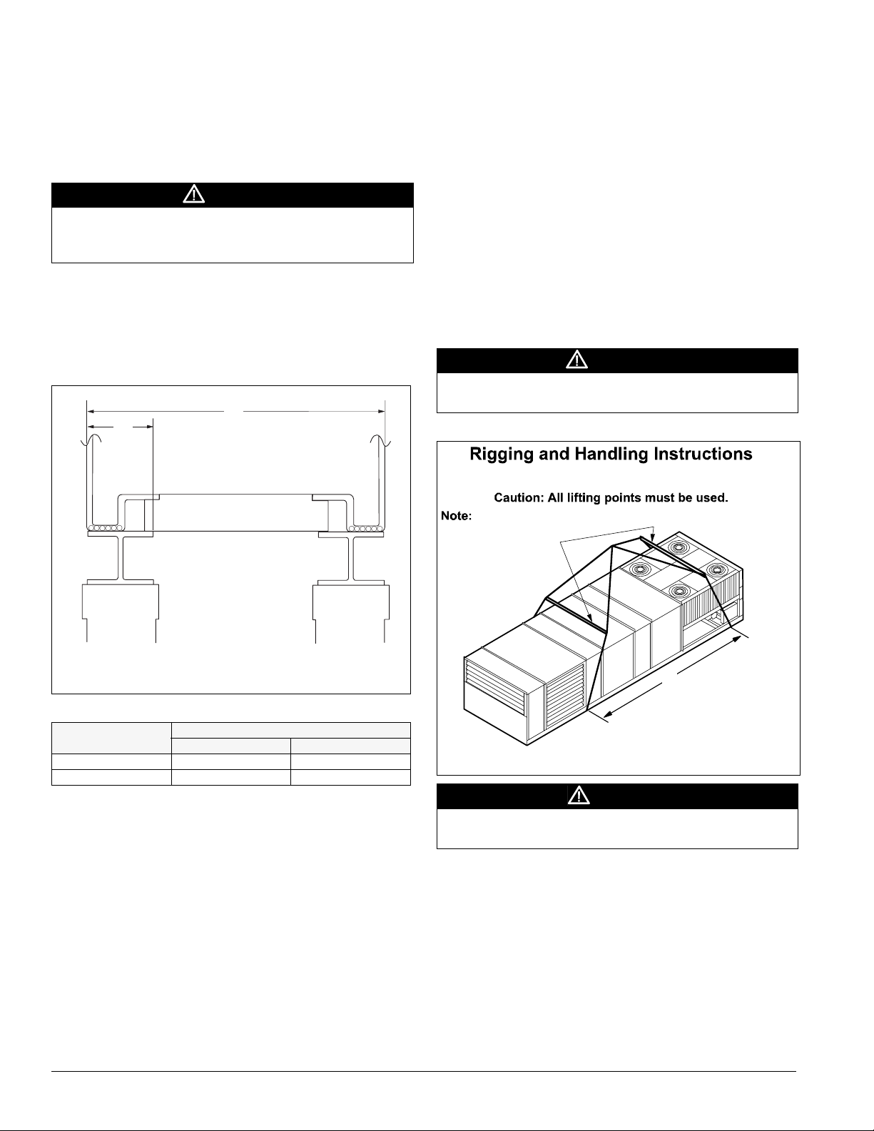
Figure 32 shows an example of the rigging instruction label
shipped with each unit.
WARNING
Use all lifting points. Improper lifting can cause severe personal
injury and property damage.
Figure 32. Rigging and handling instruction lab el
Unit has either four or six lifting points (four-point shown below).
Rigging cables must be at least as long as distance “A.”
Spreader bars
required
Maximum recommended width for structural member is 5" (127 mm) to
allow for adequate space for duct connections and electrical entry.
Table 7: W dimension (Figure 31)
Unit
015C-040C 94 2388
045C-135C 99 2538
inches mm
Dimension W
Rigging and Handling
Lifting brackets with 2" (51 mm) diameter holes are provided
on the sides of the unit.
Use spreader bars, 96" to 100" (2438 to 2540 mm) wide to
prev
ent damage to the unit cabinet. Avoid twisting or uneven
lifting of the unit. The cable length from the bracket to the
hook should always be longer than the distance between the
outer lifting points.
If the unit is stored at the constru
period, take these additional precautions:
1 Support the unit well along the length of the base rail.
2 Level the unit (no twists or uneven ground surface).
ction site for an intermediate
A
Caution: Lifting points may not
be symmetrical to center of
gravity of unit. Balast or unequal
Lift only as indicated
cable lengths may be required.
CAUTION
Lifting points may not be symmetrical to the center of gravity of
the unit. Ballast or unequal cable lengths may be required.
26 IM 738-2
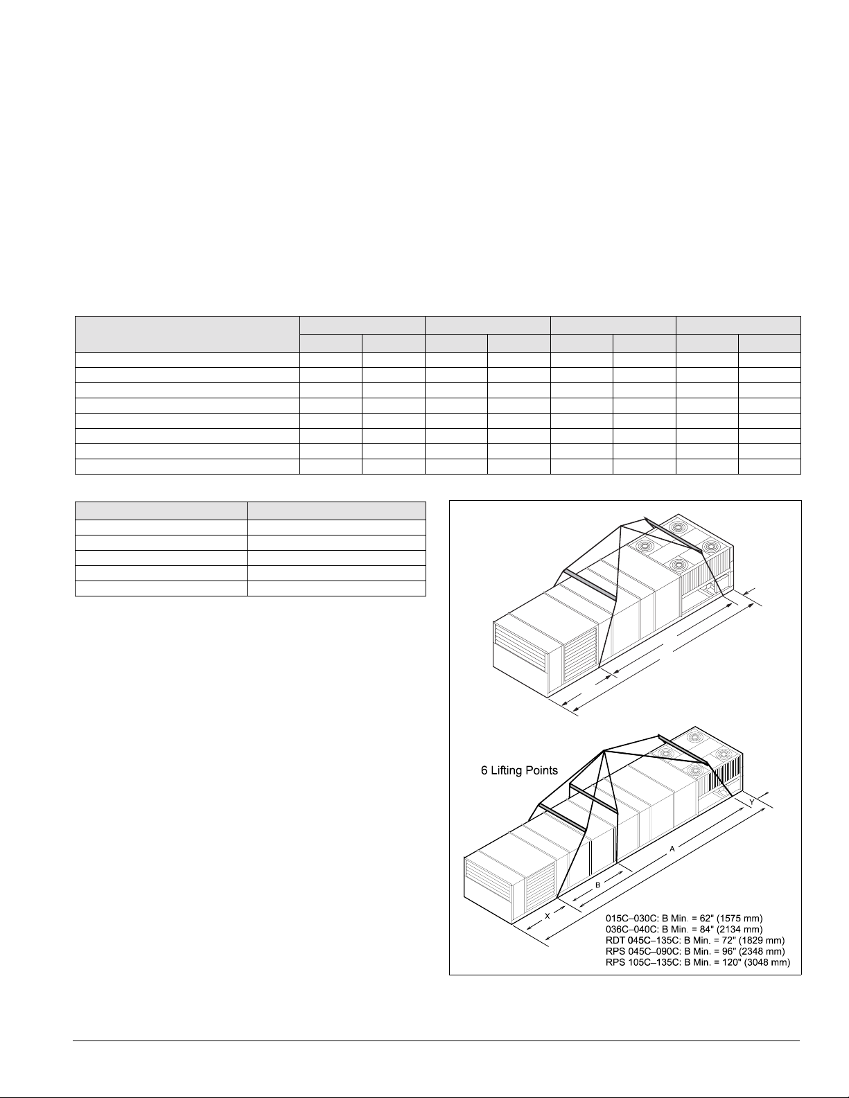
Mechanical Installation: Rigging and Handling
Lifting Points
To determine the required lifting cable lengths and whether
fo
ur-or six-point lifting is required, use Tables 8 and 9 and
Figures 33 and 34.
Referring to Figure 33 and Figure 34, note that dimension A is
the distance between the outer lift
ing points. The four outer
rigging cables must be equal to or longer than dimension A.
Dimension B shows the minimum distance between the outer
and the inner lifting points for six-point lifting. Use this to
roughly determine the required length of the middle cables for
six-point lifting. Determine dimension A by subtracting
Where:
Z = Total unit length in inches
(refer to certified drawings for this di
mension).
X = Outdoor/return air section length (refer to Table 8for this
dimension).
Y = Refer to Table 9 for this dimension (see Figure 33 and
Figure 34).If A ≤
288" (7315 mm), 4-point lifting is sufficient.
If A > 288" (7315 mm), 6-point lifting is required.
dimensions X and Y from dimension Z (e.g., A = Z – X – Y).
Table 8: X dimension (Figure 33 and Figure 34)
Outdoor/return air section
100 O.A. 000 00000
Plenum 40 1016 52 1321 48 1259 72 1829
0–30% O.A. 40 1016 52 1321 48 1259 72 1829
0–100% economizer 40 1016 52 1321 72 1829 96 2438
0–100% economizer with 15” return fan 62 1575 — — — — — —
0–100% economizer with 30” return fan 52 1321 52 1321 — — — —
0–100% economizer with 40” return fan — — 80 2032 — — — —
0–100% economizer with return fan — — — — 72 1829 96 2438
015C–030C 036C–040C 045C–075C 080C–135C
in mm in mm in mm in mm
Table 9: Y dimension (Figure 33 and Figure 34)
RPS unit size Dimension Y
015C–030C 49.5" (1257 mm)
036C & 040C 38.2" (970 mm)
045C–090C 39.5" (1003 mm)
105C 30.5" (775 mm)
115C–135C 39.5‘” (1003 mm)
Figure 33. Unit type RPS/RDT lifting points
4 L i f t i n g P o i n t s
Y
A
Z
X
IM 738-2 27
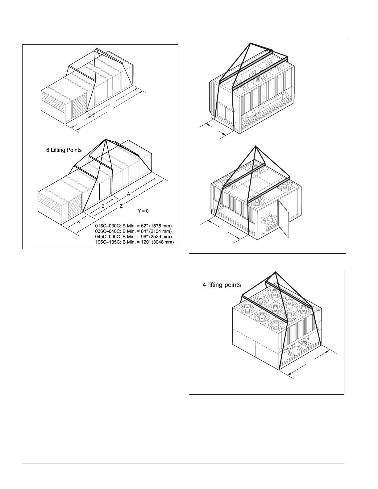
Mechanical Installation: Rigging and Handling
(
)
Figure 34. Unit type RFS or RPS/RDT factory split at
condenser
4 L i f t i n g P o i n t s
A
Z
Y = 0
X
Figure 35. Unit type RCS
4 L i f t i n g P o i n t s
A
0 - 0 0 : A M i n . = . 9 " ( 8 6 m m )
4 L i f t i n g P o i n t s
A
0 6 & 0 4 0 : A M i n . = 8 . 6 " ( 4 m m )
Figure 36. Unit type RCS or condenser section from RPS/
RDT
factory split at condenser
B
0 4 5 C – 0 6 0 C : B ( mi n .) = 5 7 " ( 1 4 4 8 m m )
0 7 0 C : B ( mi n .) = 9 3 " ( 2 3 6 2 m m )
C – 105
115C – 135C: B
min.) = 113" (2870 cm
28 IM 738-2
 Loading...