

Daikin RBRP069A61 Installation manuals
Installation manual
ROTEX LAN adapter
RBRP069A61
Installation manual
ROTEX LAN adapter
English
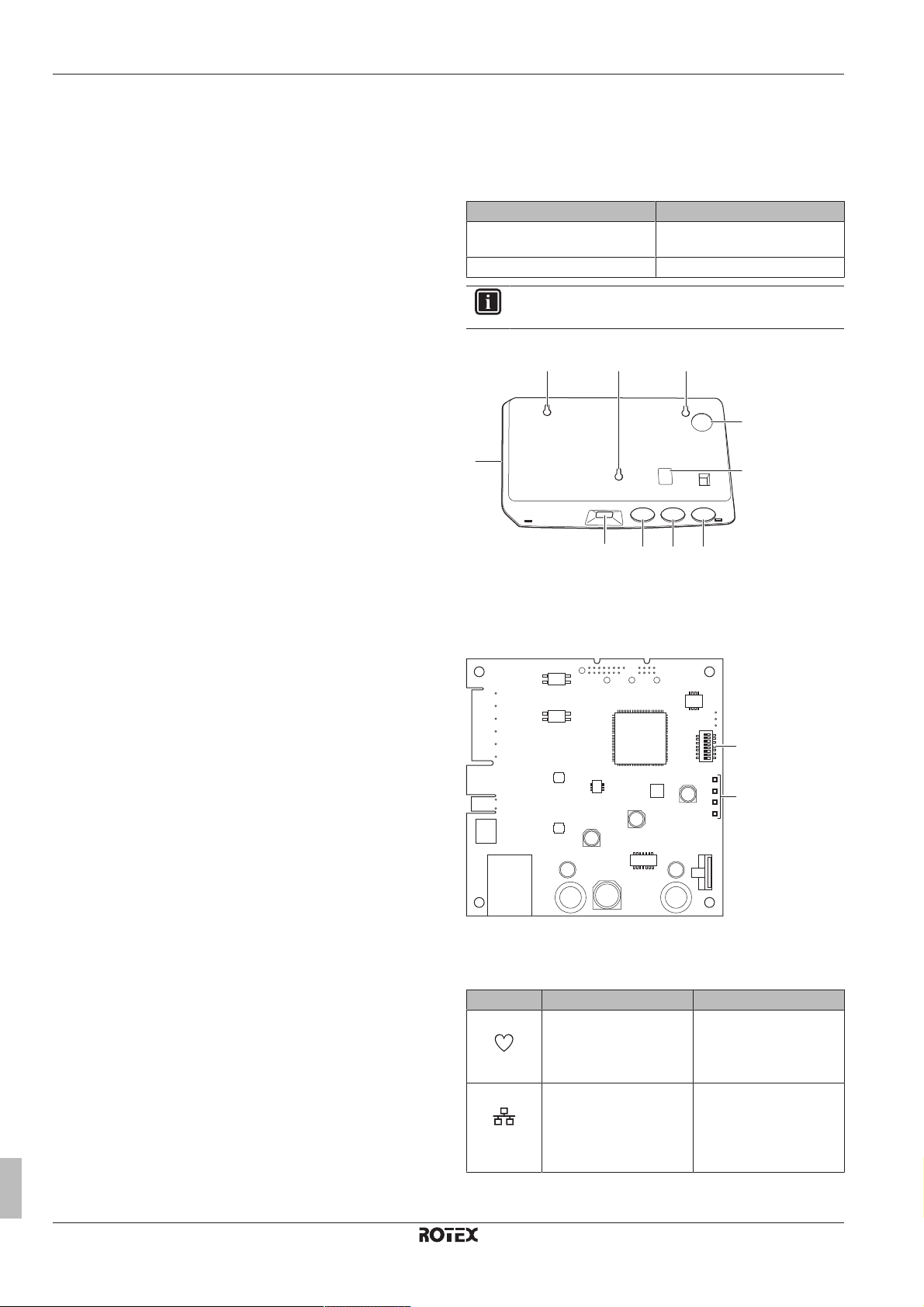
Table of contents
a a
bd b b
a
c
c
e
X1A
X2A
X3A
X4A
b
a
LD1
LD2
LD3
LD4
Table of contents
1 About the documentation 2
1.1 About this document.................................................................. 2
2 About the product 2
2.1 Compatibility.............................................................................. 3
2.2 System requirements ................................................................ 3
3 About the box 3
3.1 To unpack the LAN adapter ...................................................... 3
4 Preparation 4
4.1 Installation site requirements..................................................... 4
4.2 Overview of electrical connections ............................................ 4
4.2.1 Router ......................................................................... 4
4.2.2 Indoor unit ................................................................... 4
4.2.3 Electricity meter .......................................................... 5
4.2.4 Solar inverter/energy management system ................ 5
5 Installation 5
5.1 Mounting the LAN adapter ........................................................ 5
5.1.1 To mount the rear casing to the wall........................... 6
5.1.2 To mount the PCB to the rear casing.......................... 6
5.2 Connecting the electrical wiring................................................. 6
5.2.1 To connect the indoor unit .......................................... 7
5.2.2 To connect the router.................................................. 7
5.2.3 To connect the electricity meter .................................. 7
5.2.4 To connect the solar inverter/energy management
system......................................................................... 7
5.3 Finishing the LAN adapter installation....................................... 8
5.3.1 LAN adapter serial number ......................................... 8
5.3.2 To close the LAN adapter ........................................... 8
6 Starting up the system 8
2 About the product
The ROTEX LAN adapter allows for app control of the ROTEX heat
pump system and, depending on the model, allows for the
integration of the heat pump system in a Smart Grid application.
The LAN adapter is available in 2 versions:
Model Functionality
RBRP069A61 App control + Smart Grid
application
RBRP069A62 App control only
INFORMATION
Not all models are available in all sales regions.
Components: casing
a Wall mounting holes
b Knockout holes (wiring from the bottom)
c Knockout holes (wiring from the rear)
d Ethernet connection
e Status LEDs
Components: PCB
1 About the documentation
1.1 About this document
Target audience
Authorised installers
Documentation set
This document is part of a documentation set. The complete set
consists of:
▪ General safety precautions
▪ Safety instructions that you must read before installing
▪ Format: Paper (in the box of the indoor unit)
▪ Installation manual:
▪ Installation instructions
▪ Format: Paper (supplied in the kit)
▪ Installer reference guide:
▪ Installation instructions, configuration, application guidelines,…
▪ Format: Digital files on the ROTEX homepage
Latest revisions of the supplied documentation may be available on
the regional ROTEX website or via your dealer.
The original documentation is written in English. All other languages
are translations.
Installation manual
2
X1A~X4A Connectors
a DIP switch
b Status LEDs
Status LEDs
LED Description Behaviour
LD1
Indication of power to the
adapter, and of normal
operation.
▪ LED flashing: normal
operation.
▪ LED NOT flashing: no
operation.
LD2
Indication of TCP/IP
communication with the
router.
▪ LED ON: normal
communication.
▪ LED flashing:
communication
problem.
4P509999-1B – 2018.10
RBRP069A61
ROTEX LAN adapter
3 About the box
a
b
c
a
a
a
2× 1× 1×
a b c
1×
d
3× 3× 3×
f
1×
e f g h4×i
1× 1×
j k
LED Description Behaviour
LD3
LD4
Indication of
communication with the
indoor unit.
(a)
Indication of Smart Grid
activity.
(a) This LED is ONLY active for RBRP069A61 (present for
RBRP069A62, but ALWAYS inactive).
▪ LED ON: normal
communication.
▪ LED flashing:
communication
problem.
▪ LED ON: Smart Grid
functionality of the
indoor unit is controlled
by the LAN adapter.
▪ LED OFF: system
operating in normal
operation conditions
(space heating/cooling,
production of domestic
hot water), or running in
the "Normal
operation"/"Free
running" Smart Grid
operation mode.
2.1 Compatibility
Make sure your ROTEX system is compatible for use with the LAN
adapter (app control and/or Smart Grid applications). For more
information, see the installer reference guide of the ROTEX system.
INFORMATION
For instructions on how to perform a software update, see
the installer reference guide.
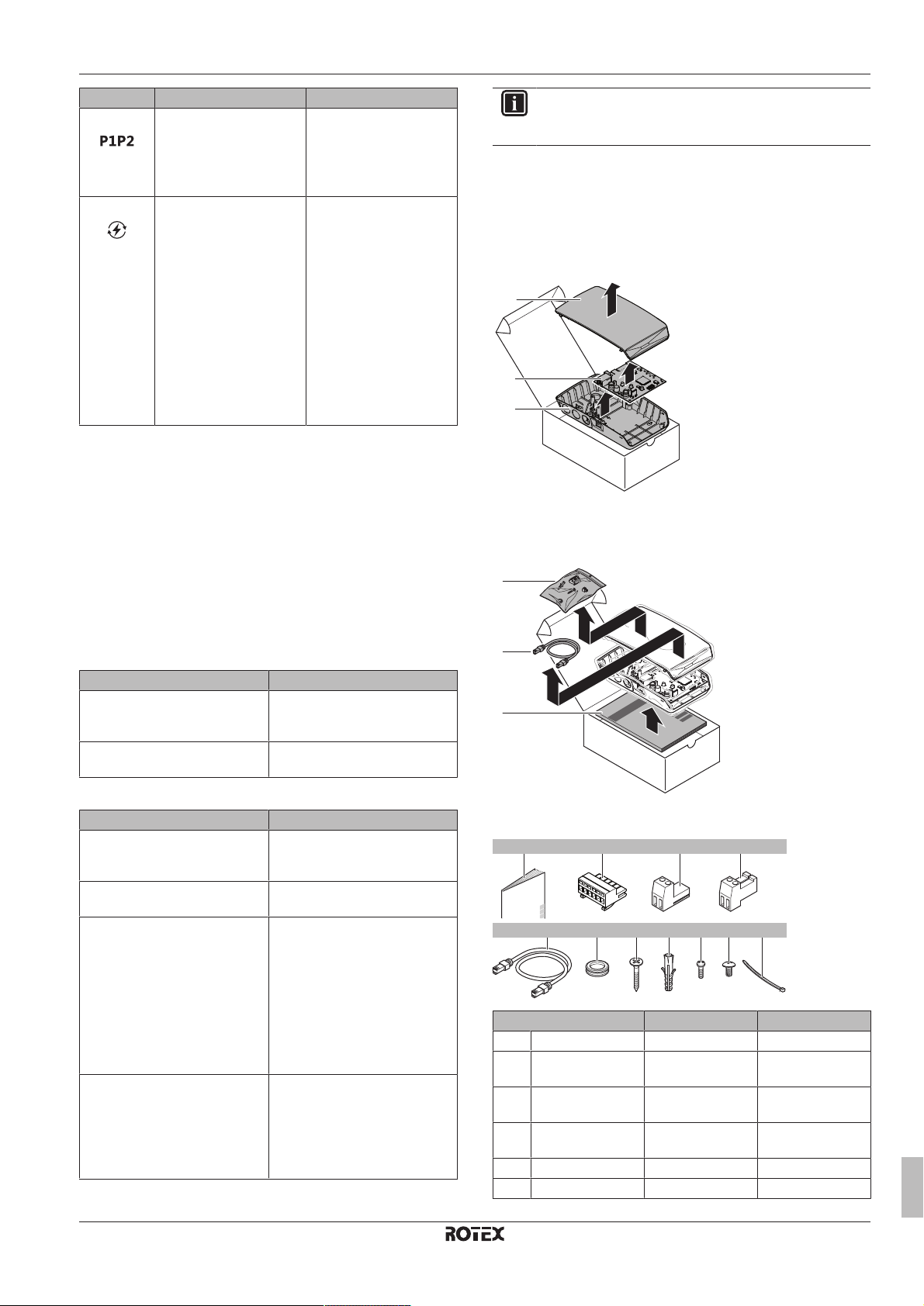
3 About the box
3.1 To unpack the LAN adapter
1 Unpack the LAN adapter.
a Front casing
b PCB
c Rear casing
2 Separate the accessories.
2.2 System requirements
The requirements posed on the ROTEX system depend on the LAN
adapter application/system layout.
App control
Item Requirement
LAN adapter software It is recommended to ALWAYS
Unit control method Make sure user interface setting
Smart Grid application
Item Requirement
LAN adapter software It is recommended to ALWAYS
Unit control method Make sure user interface setting
Domestic hot water settings To allow for energy buffering in
Power consumption control
settings
keep the LAN adapter software
up-to-date.
[C‑07] is set to 2:RTControl.
keep the LAN adapter software
up-to-date.
[C‑07] is set to 2:RTControl.
the domestic hot water tank:
▪ Domestic hot water setting
[E-05] (DHW operation) MUST
be set to "DHW" ([E-05]=1).
▪ Domestic hot water setting
[E-06] (DHW tank type.) MUST
be set to "DHW
tank" ([E-06]=1).
▪ Power consumption control
setting [4‑08] (Mode) MUST be
set to "Continuous" ([4‑08]=1).
▪ Power consumption control
setting [4‑09] (Type) MUST be
set to "Power" ([4‑09]=1).
a Accessories
Accessories: RBRP069A61
Accessory RBRP069A61 RBRP069A62
a Installation manual O O
b 6‑pole slide
connector for X1A
c 2‑pole slide
connector for X2A
d 2‑pole slide
connector for X3A
e Ethernet cable O O
f Grommets O O
O —
O —
O O
RBRP069A61
ROTEX LAN adapter
4P509999-1B – 2018.10
Installation manual
3
4 Preparation
>30 mm >30 mm
>90 mm
(a)
>160 mm
(b)
X4A
4
N
L
3
2
1
2
1
X1A
X2A
X3A
a1
A
b
c
a2
d
Accessory RBRP069A61 RBRP069A62
g Screws to mount
O O
rear casing
h Plugs to mount rear
O O
casing
i Screws to mount
O O
PCB
j Screw to close
O O
front casing
k Cable tie O —
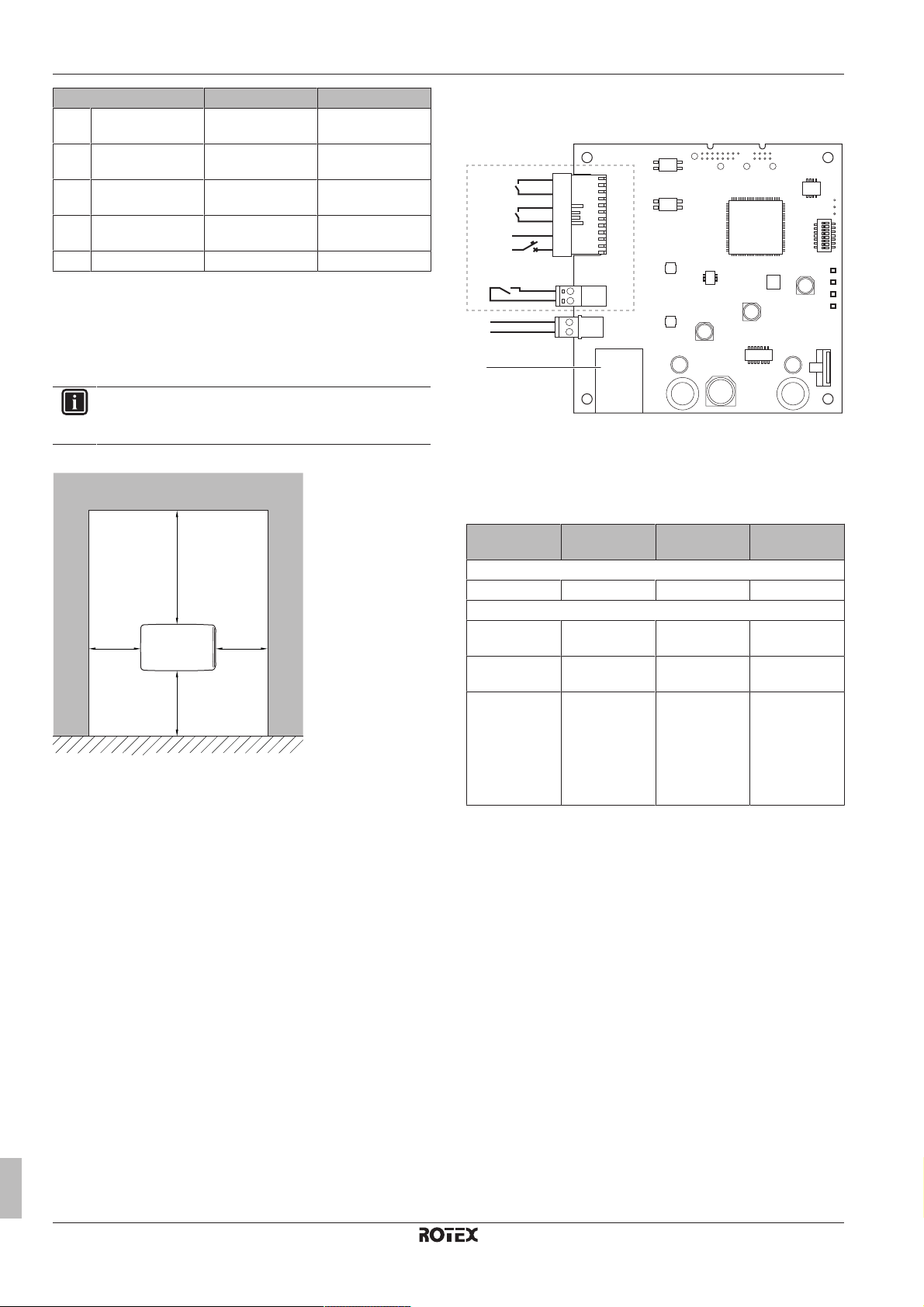
4 Preparation
4.1 Installation site requirements
INFORMATION
Also read the maximum cable length requirements set out
in "4.2Overview of electrical connections"on page4.
▪ Mind the following spacing installation guidelines:
(a) Provide enough space to connect the Ethernet cable
without exceeding its minimum bend radius (typically
90mm)
(b) Provide enough space to open the casing with a flat-blade
screwdriver (typically 160mm)
▪ The LAN adapter is designed to be wall-mounted in dry, indoor
locations only. Make sure the installation surface is a flat and
vertical non-combustible wall.
▪ The LAN adapter is designed to be mounted in the following
orientation only: with the PCB on the right-hand side in the casing,
and the Ethernet connector facing the floor.
▪ The LAN adapter is designed to operate in ambient temperatures
ranging from 5~35°C.
4.2 Overview of electrical connections
Connectors
A RBRP069A61 only
a1 To solar inverter/energy management system
a2 230VAC detection voltage
b To electricity meter
c To indoor unit (P1/P2)
d To router
Connections
Connection Cable section Wires Maximum
Accessory cables
Router (X4A) — — 50/100m
Field-supplied cables
Indoor unit (P1/
0.75~1.25mm
2
(b)
2
P2) (X3A)
Electricity meter
0.75~1.25mm
2
(c)
2
(X2A)
Solar inverter/
energy
0.75~1.5mm2Depends on
application
management
system +
230VAC
detection
voltage (X1A)
(a) The Ethernet cable delivered as an accessory is 1m long.
It is, however, possible to use a field-supplied Ethernet
cable. In this case, respect the maximum allowed distance
between LAN adapter and router, which is 50m in case of
Cat5e cables, and 100m in case of Cat6 cables.
(b) These wires MUST be sheathed. Recommended strip
length: 6mm.
(c) These wires MUST be sheathed. Recommended strip
length: 6mm.
(d) All wiring to X1A MUST be H05VV. Required strip length:
7mm. For more information, see "4.2.4Solar inverter/
energy management system"on page5.
(d)
cable length
(a)
200m
100m
100m
Installation manual
4
4.2.1 Router
Make sure the LAN adapter can be connected via a LAN connection.
The minimum category for the Ethernet cable is Cat5e.
4.2.2 Indoor unit
For power and communication with the indoor unit, the LAN adapter
is connected to the indoor unit's P1/P2 terminals via a 2‑wire cable.
There is NO separate power supply: the adapter gets its power from
the indoor unit's P1/P2 terminals.
RBRP069A61
ROTEX LAN adapter
4P509999-1B – 2018.10
 Loading...