

Page 1
Operation manual
Wall-mounted condensing boiler
R2CND024A4AA
R2TND012A4AA
R2TND018A4AA
R2TND024A4AA
Operation manual
Wall-mounted condensing boiler
English
Page 2

Table of Contents
Table of Contents
1 Introduction 2
1.1 About the unit ............................................................................ 2
1.2 About the documentation .......................................................... 2
1.2.1 Meaning of warnings and symbols.............................. 2
2 Safety instructions 2
2.1 Installation ................................................................................. 2
2.2 Smell of gas............................................................................... 3
2.3 Modifications on the unit............................................................ 3
2.4 Gas conversion ......................................................................... 3
2.5 For the user ............................................................................... 3
3 Operation 3
3.1 User interface ............................................................................ 3
3.1.1 Buttons and dials ........................................................ 4
3.1.2 LCD screen ................................................................. 4
3.1.3 Status indicator ........................................................... 4
3.2 Operating the unit...................................................................... 4
3.2.1 To switch ON the unit.................................................. 4
3.2.2 About the low water temperature function .................. 4
3.2.3 About the electronic gas adaptive system calibration. 4
3.3 Basic usage............................................................................... 4
3.3.1 About the home screen............................................... 4
3.3.2 To select the operation mode ..................................... 5
3.3.3 Possible operation modes........................................... 5
3.3.4 Changing temperature setpoints................................. 5
3.3.5 Possible central heating operation modes.................. 6
3.3.6 About the central heating ECO mode ......................... 6
3.3.7 About the domestic hot water operation ..................... 6
3.3.8 About the domestic hot water comfort mode .............. 7
3.3.9 About the boiler frost protection.................................. 7
3.4 Error handling............................................................................ 7
3.5 Menu functions .......................................................................... 7
3.5.1 To use menu level 1.................................................... 7
3.5.2 Info menu .................................................................... 7
3.5.3 User settings menu ..................................................... 8
3.5.4 Installer settings menu ................................................ 9
4 Maintenance and cleaning 9
4.1 To clean the outer surface of the unit........................................ 9
5 Energy saving tips 9
6 Contact 9
7 Error codes 9
Model Type Domestic hot water
supply
R2TND018A4AA R2TND018 Storage tank External
R2TND024A4AA R2TND024 Storage tank External
A control unit, which contains a user interface, controls the ignition,
safety systems, and other actuators. User interaction is provided via
that user interface, which is composed of an LCD screen, push
buttons, and two dials, and which is located on the front cover of the
unit.
Filling loop
1.2 About the documentation
The instructions contained in this document are intended to guide
you through the operation of the unit. Damage caused by nonobservance of these instructions are not under the responsibility of
ROTEX.
▪ The original documentation is written in English. All other
languages are translations.
▪ The precautions described in this document are written for users
and cover very important topics, follow them carefully.
▪ Please read the instructions in the manual carefully, for your
safety and health.
▪ Please keep this manual for future reference throughout the unit's
period of use.
▪ Request the installer to inform you about the settings that he
made to configure your system.
1.2.1 Meaning of warnings and symbols
DANGER
Indicates a situation that results in death or serious injury.
WARNING
Indicates a situation that could result in death or serious
injury.
CAUTION
Indicates a situation that could result in minor or moderate
injury.
NOTICE
Indicates a situation that could result in equipment or
property damage.
INFORMATION
Indicates useful tips or additional information.
1 Introduction
1.1 About the unit
This ROTEX unit is a wall-mounted gas-fired condensing boiler that
can supply heat to central heating systems, as well as supply
domestic hot water. Depending on settings, it is possible to use the
unit solely for hot water or solely for central heating. Hot water
supply type can be instantaneous or by means of a hot water
storage tank. The type of the boiler can be recognised from the
model name written on the identification label, which is located at the
right cover of the unit. See table below:
Model Type Domestic hot water
supply
R2CND024A4AA R2CND024 Instantaneous External
R2TND012A4AA R2TND012 Storage tank External
Operation manual
2
Filling loop
2 Safety instructions
Always observe the following safety instructions and regulations.
2.1 Installation
WARNING
Installation, service, maintenance and repair of the boiler
can only be carried out by suitably qualified competent
persons, in accordance with the applicable legislation,
regulations, rules and guidelines.
WARNING
The unit may only be operated with its casing properly
mounted. Otherwise, in unfavourable conditions, material
damage or even injury or death can result.
R2CND024A4AA + R2TND012~024A4AA
Wall-mounted condensing boiler
3P469438-4D – 2017.07
Page 3
3 Operation
a
e f g
cb
d
CAUTION
A discharge pipe must be connected to the condensate
trap in order to prevent contact with the condensate.
In case your skin comes into contact with condensate, the contact
location should be washed with plenty of water. Condensate liquid
must never be used for purposes of cleaning, watering plants, or
drinking.
2.2 Smell of gas
DANGER
This is a gas unit. Gas leaks might lead to poisoning and
explosions.
If you smell gas:
▪ Do not use any electrical switches, including light switches.
▪ Do not use telephones in the affected area.
▪ Do not use naked flames, such as matches or lighters.
▪ Do not smoke.
▪ Turn off the main gas supply.
▪ Open windows and doors.
▪ Warn other people in the building.
▪ Get out of the building.
▪ Inform your gas supplier, service agent or other competent
person.
2.3 Modifications on the unit
DANGER
Malfunctions can lead to poisoning and explosions. Never
put the safety devices out of operation, nor tamper with
them so as to impair their function.
CAUTION
An inappropriate modification may cause damage. Never
tamper with the boiler or other parts of the system. Never
attempt to perform maintenance or repair yourself. Call a
qualified service agent.
This unit is able to be operated with both natural gas and LPG. The
preset gas type is indicated on the identification label of your unit. If
you desire to use your unit with the other fuel type, contact your
service agent.
2.5 For the user
CAUTION
Any misuse is forbidden. The manufacturer is not
responsible for any malfunctions and/or damage that may
occur due to misuse.
▪ Your unit is intended as a heater for central heating systems and
for domestic hot water generation. Any other use is considered as
"misuse".
▪ If you are not sure how to operate the unit, contact your service
agent.
▪ This appliance can be used by children aged from 8 years and
above and persons with reduced physical, sensory or mental
capabilities or lack of experience and knowledge if they have been
given supervision or instruction concerning use of the appliance in
a safe way and understand the hazards involved. Children shall
not play with the appliance. Cleaning and user maintenance shall
not be made by children without supervision.
CAUTION
Do not rinse the unit. This may cause electric shocks or
fire.
NOTICE
▪ Do not place any objects or equipment on top of the
unit.
▪ Do not sit, climb or stand on the unit.
3 Operation
3.1 User interface
CAUTION
Do not use sprays, solvents, chlorinated cleaning agents,
paint, and adhesives in the vicinity of the unit. These
substances can cause corrosion, even in the flue system.
DANGER
Do not damage or remove any seals on components. Only
qualified persons are allowed to alter sealed components.
Do not make any modifications on:
▪ Boiler
▪ Gas, water or power supply
▪ Flue system
2.4 Gas conversion
WARNING
Never attempt to do gas conversion yourself. Only qualified
persons can do gas conversion. Contact your service
agent.
R2CND024A4AA + R2TND012~024A4AA
Wall-mounted condensing boiler
3P469438-4D – 2017.07
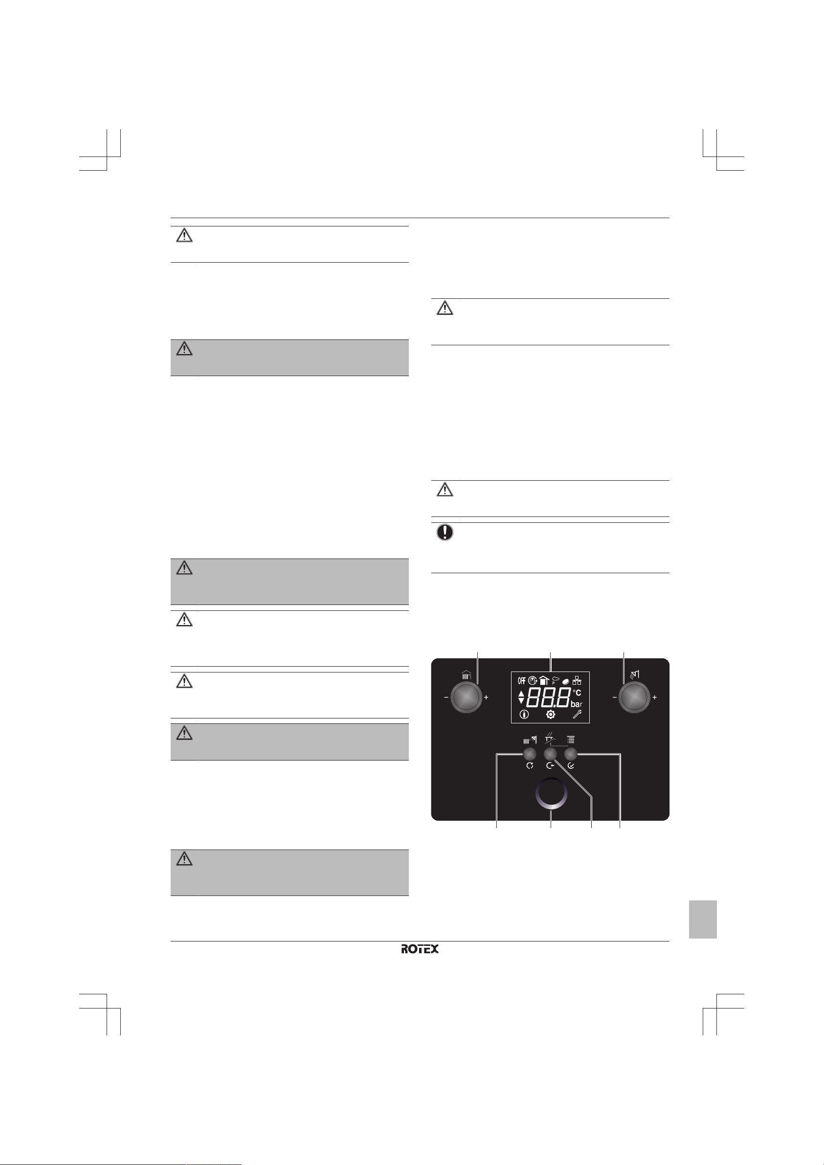
a Left dial
b LCD screen
c Right dial
d Mode / Reset
e Status indicator
f Cancel / Back
g Menu / Enter
Operation manual
3
Page 4
3 Operation
3.1.1 Buttons and dials
The three buttons and two dials on the user interface have various
functions according to different situations, which are stated in the
table below:
Button/Dial Function Description
Mode /
Reset
Cancel /
Back
Menu / Enter Menu Enter the menu function.
Left dial User
Right dial User
Mode Change mode between summer,
winter, central heating only, standby
and full-off.
Reset Reset the lockout error.
Cancel Cancel changes.
Back Go back to the parent menu.
Enter Passing on to the next level in the
menu structure.
Confirm Confirmation of changes.
Central heating temperature setpoint.
interaction
level
Menu level Selection of info, user, service menu.
interaction
level
Menu level ▪ Selection parameter index.
This is either the central heating flow
temperature, the room temperature,
or the virtual room temperature,
depending on the system
configuration.
Domestic hot water temperature
setpoint.
▪ Change parameter values.
3.1.2 LCD screen
LCD screen is the monitor of the user interface. You can see the
boiler operation mode, setpoints, information about actuators and
menu parameters on this screen.
The LCD screen has a sleeping function. After one minute of noninteraction with the user interface, the screen darkens. Pressing any
button or rotating any dial awakens the display.
When you interact with the user interface, the LCD screen will show
the home screen of the active operation mode and the related
setpoint, depending on the system configuration (see "3.3.3Possible
operation modes"on page5).
Status icons
Meaning of icons that appear on the LCD screen:
Icon Description
Operation mode: Standby mode
Domestic hot water operation enabled
Domestic hot water comfort mode is enabled
Central heating operation enabled
Room temperature
Outdoor sensor connection
Central heating ECO mode enabled
Network connection
Info menu
User settings menu
Service settings menu
3.1.3 Status indicator
The status indicator gives first level feedback on the operation mode
and status of the boiler.
Status Description
Standby When there is no heat demand, the status
indicator shows this with a kind of breathing
pulsation of the blue and white LED.
Flame At the moment flame ignites for central heating or
domestic hot water, the ring flashes to its
maximum, then constantly keeps glowing during
burner operation.
Error The status indicator will go into error mode when a
warning, lockout or blocking error occurs (see
"3.4Error handling"on page7). During the error
condition the status indicator continuously shows
the red blinking LED.
NOTICE
In warning error, the status indicator colour turns to blue
while the boiler is operating.
3.2 Operating the unit
3.2.1 To switch ON the unit
1 Connect the unit to the main power supply.
2 Press the "Mode" button for 5seconds to switch ON the unit.
3 After that, you can select an operation mode by pressing the
"Mode" button shortly.
Use of the unit is explained in following parts of this manual.
3.2.2 About the low water temperature function
The low water temperature function is a safety function that takes
place at first central heating operation after each power supply
interruption and at first central heating operation after each 90 days.
When this function is active, boiler operates according to a defined
set value for around 15 minutes and the icon blinks. After this
function is ended, normal operation goes on.
INFORMATION
Low water temperature function is a safety function and it
cannot be disabled.
3.2.3 About the electronic gas adaptive system calibration
The electronic gas adaptive system calibrates itself in predetermined time intervals. First calibration takes place just after first
burner activation after each power ON. Calibration process duration
is around 60 seconds and the icon blinks. After calibration is
ended, boiler modulates to required capacity. Calibration process
has no effect on boiler operation.
3.3 Basic usage
3.3.1 About the home screen
It is the screen that is displayed after activating the LCD screen with
one of the dials or buttons. You can use the home screen to read out
settings that are meant for daily use. What you can see on the home
screen depends on your system configuration.
The following home screens may be possible:
▪ Room temperature (ROTEX room thermostat connected)
▪ Central heating set temperature
Operation manual
4
R2CND024A4AA + R2TND012~024A4AA
Wall-mounted condensing boiler
3P469438-4D – 2017.07
Page 5

3 Operation
(5 s)
(5 s)
a
c
b
d
e
▪ Virtual room temperature (with outdoor sensor)
▪ Domestic hot water set temperature
▪ System pressure (at standby mode)
3.3.2 To select the operation mode
The operation mode can be changed by pressing the "Mode" button
( ).
a Central heating only mode
b Standby mode
c Summer mode
d Winter mode
e Full-off mode
3.3.3 Possible operation modes
Operation mode Description
Central heating only mode ▪ Only central heating operation mode
is enabled.
▪ The central heating temperature
setpoint (which setpoint is shown
depends on the system
configuration; see "3.3.5 Possible
central heating operation modes"on
page 6) and the icon is shown
on the home screen.
▪ The icon blinks if central heating
operation is active.
Standby mode ▪ Both central heating and domestic
hot water operation modes are
disabled.
▪ The protection functions such as
frost protection are still active at
standby mode.
▪ The home screen shows the system
pressure, as well as the icon.
Summer mode ▪ Only domestic hot water operation
mode is enabled. Central heating
operation mode is disabled. The
boiler will only produce heat for
domestic hot water.
▪ The domestic hot water setpoint,
and the icon is shown on the
home screen.
▪ The icon blinks if domestic hot
water operation is active.
Operation mode Description
Winter mode ▪ Both domestic hot water operation
mode and central heating operation
mode are enabled. The boiler can
produce domestic hot water, as well
as produce heat for central heating.
▪ The central heating temperature
setpoint (which setpoint is shown
depends on the system
configuration; see "3.3.5 Possible
central heating operation modes"on
page 6), and the icon, as well
as the icon are shown on the
home screen. When domestic hot
water operation is active, domestic
hot water setpoint is shown on the
home screen.
▪ The icon blinks if domestic hot
water operation is active.
▪ The icon blinks if central heating
operation is active.
Full-off mode ▪ Both central heating and domestic
hot water operation modes are
disabled.
▪ LCD display will be darkened and
will not be activated with any user
interaction.
▪ The protection functions such as
frost protection are still active at fulloff mode.
▪ Full-off mode is activated and
deactivated if "Mode" button is
pressed for 5seconds while boiler is
in any mode.
3.3.4 Changing temperature setpoints
Temperature setpoints can be changed with the Right/Left dials.
To change the central heating temperature setpoint
1 Turn the left dial while you are at the home screen. The setpoint
screen will appear as shown below and the setpoint can be
adjusted by turning the left dial. Note: The icon means you are
at the setpoint screen.
2 To apply changes done, wait for 3seconds or press the "Enter"
button. Pressing the "Cancel" button cancels the changes done.
R2CND024A4AA + R2TND012~024A4AA
Wall-mounted condensing boiler
3P469438-4D – 2017.07
Operation manual
5
Page 6

3 Operation
To change the domestic hot water setpoint
1 Turn the right dial while you are at the home screen. The
setpoint screen will appear as shown below and the setpoint
can be adjusted by turning the right dial. Note: The icon
means you are at the setpoint screen.
2 To apply changes done, wait for 3seconds or press the "Enter"
button. Pressing the "Cancel" button cancels the changes done.
NOTICE
To be able to change the setpoint of central heating or
domestic hot water, the corresponding operation mode
must be enabled. If it is not, the related dial has no
function.
3.3.5 Possible central heating operation modes
Mode Description
Boiler only The case that the system only
contains the boiler. No room
thermostat or outdoor sensor are
connected. The central heating water
temperature setpoint is displayed. The
setpoint can be adjusted with the left
dial.
The icon is shown on the screen
when the central heating operation
mode is enabled.
Combination with ROTEX
Opentherm room
thermostat (DOTT )
The case that ROTEX Opentherm
room thermostat is connected to the
boiler. Room temperature setpoint is
displayed. The room temperature
setpoint can be adjusted from the user
interface by means of the left dial or
from the ROTEX room thermostat.
The icon is shown on the screen
instead of the icon when central
heating operation mode is enabled.
Mode Description
Boiler + outdoor sensor
(Weather compensation)
NOTICE
To enable weather compensation, the heating slope value
must be higher than "5" (see "User settings menu:
Parameters (short)"on page8).
INFORMATION
If an outdoor sensor is connected to the boiler together
with an Opentherm room thermostat (whether DOTT or
not), the rules of the case "Combination with Opentherm
room thermostat" are applicable. The outdoor sensor only
provides outdoor temperature data to the room thermostat
for water temperature calculation.
The case that outdoor sensor is
connected to the boiler. In this case,
the central heating water temperature
is regulated according to the outdoor
temperature. The virtual room
temperature setpoint is diplayed. The
virtual room temperature setpoint can
be adjusted by means of left dial.
Increasing or decreasing the setpoint
value reflects to the central heating
water temperature and the room
temperature, respectively.
The and icons are shown on the
screen when central heating operation
mode is enabled.
3.3.6 About the central heating ECO mode
The central heating ECO mode provides more economic central
heating. Main purpose of the ECO mode is to operate the boiler at
the condensing temperature range so to increase the efficiency.
ECO mode can be activated at any central heating operation mode
explained above.
ECO mode can be enabled from the user settings menu (see "User
settings menu: Parameters (short)"on page8).
INFORMATION
ECO mode is only for central heating, it has no effect to
domestic water heating.
When central heating ECO mode is enabled, icon is shown on the
screen while the central heating operation mode is enabled.
3.3.7 About the domestic hot water operation
This unit supplies domestic hot water by way of a plate heat
exchanger (instantaneous) or by way of a hot water storage tank
according to model of the boiler.
If the boiler is instantaneous type, domestic hot water operation is
activated when water is being tapped. Water flow rate must be at
least 2.5l/min.
If it is storage tank type, domestic hot water operation is activated
according to storage tank temperature value.
The icon blinks when domestic hot water operation is active.
Operation manual
6
INFORMATION
Domestic hot water operation mode must be enabled for
the boiler to be able to produce domestic hot water. (i.e.
summer mode or winter mode).
R2CND024A4AA + R2TND012~024A4AA
Wall-mounted condensing boiler
3P469438-4D – 2017.07
Page 7

3 Operation
3.3.8 About the domestic hot water comfort mode
The domestic hot water comfort mode includes a domestic hot water
pre-heat function and a domestic hot water post-heat function. When
the comfort mode is enabled, both pre-heat and post-heat functions
are enabled.
The pre-heat function is a self-learning algorithm according to which
the boiler will heat up the domestic hot water, before the tapping
demand. The algorithm is based on your personal use pattern of the
last 24hours.
Note: Independent of personal use pattern, comfort mode
preheating function could be adjusted to operate continuously from
the user settings.
The post-heat function heats up the domestic hot water heat
exchanger after tapping, when the flow temperature of the boiler is
below the domestic hot water temperature setpoint.
Comfort mode can be enabled from the user settings menu (see
"User settings menu: Parameters (short)"on page8).
INFORMATION
Domestic hot water comfort mode is only valid for
instantaneous type hot water supply types.
When the domestic hot water comfort mode is enabled, the icon is
shown on the screen.
The icon blinks when the burner is on for comfort mode.
Error
type
Lockout Blocked and a
In case of a warning or a blocking error, the user interface will leave
error mode and return to the home screen when the cause of the
error disappears.
In case of a lockout error, the boiler needs to be reset. Press the
"Reset" button to remove the error, if the cause of the error is gone.
If the cause of the error is still there, the user interface will enter
error mode again. When the error is solved, the user interface
returns to the home screen.
If you turn any dial or press any button (except the "Reset" button)
during an error, the user interface will display the home screen. After
the timeout without any interaction, instead of darkening, the user
interface will enter error mode.
Boiler operation User interface and status
indicator
The status indicator enters error
reset is required
NOTICE
A table with all error codes, the reasons for their
appearance, and possible solutions, is located at the very
end of this manual.
mode. The LCD screen stays active
and displays the error code. Also,
the icon starts blinking, indicating
that a reset is required.
3.5 Menu functions
3.3.9 About the boiler frost protection
Frost protection safety system: This function protects the unit and
heating installation from frost damages. This protection activates the
boiler pump when the water temperature drops below 13°C and it
activates the burner when the water temperature drops below 8°C
(factory setting). The unit keeps running until the temperature
reaches 30°C. To enable this function, the unit must be connected to
the power supply and its main gas valve must be open. Any damage
caused by frost is not covered by the warranty. Frost Protection is
enabled in all modes, including standby mode and full-off mode.
WARNING
If the boiler is not connected to the power supply, frost
protection is not active. Consequently, the water may
freeze and cause cracks. The manufacturer is not
responsible for any damage that may occur this way.
NOTICE
When not using the boiler, we strongly recommend not to
cut off the electric supply to the boiler.
3.4 Error handling
When an error occurs, the normal behaviour of the user interface is
interrupted, and the status of the status indicator is affected.
However, be aware that not all errors have the same effect on the
user interface and the status indicator.
3.5.1 To use menu level 1
1 Press the "Menu" button while you are at home screen to go the
Menu screen. This is menu level 1 screen.
2 To switch between info, user settings and service settings, turn
the left dial.
3 To leave the menu and return to the home screen, press "Back"
for 2seconds.
When there is no user interaction for one minute, the user interface
will leave the menu and switch to the blank screen.
Error
type
Warning Continue The status indicator does not enter
Blocking Blocked, turns back
R2CND024A4AA + R2TND012~024A4AA
Wall-mounted condensing boiler
3P469438-4D – 2017.07
Boiler operation User interface and status
indicator
error mode if the burner is on. It
turns to red when the burner is off.
The LCD screen stays active and
displays the error code.
The status indicator enters error
to operation if
cause disappears
mode. The LCD screen stays active
and displays the error code.
3.5.2 Info menu
Info menu: Parameters
The info menu ( ) covers all possible information that is made
available to the end user and to the installer. This parameters are
read only and cannot be changed.
# Description (short) Unit
A00 Actual flow temperature °C
A01 Actual return temperature °C
Operation manual
7
Page 8

3 Operation
a
# Description (short) Unit
A02 Actual domestic hot water temperature °C
A03 Actual flue temperature °C
(a)
A04
Actual outdoor temperature (if outdoor
°C
sensor is connected, otherwise "--")
(a)
A05
Actual solar temperature (if solar sensor is
°C
connected, otherwise "--")
A06 Actual water pressure bar
A07 Actual domestic hot water flow rate l/min
(b)
A08
A09
Current set point of burner capacity %
(b)
Actual capacity of boiler in relation to
%
nominal capacity
(c)
A10
A11 Status of On-Off room thermostat,
Actual phase of the burner —
—
indicate heat demand (HC1)
A12 Actual error code of boiler —
A13 Actual fan speed (rpm/100) rpm
A14 Current setpoint of boiler pump %
(a) Not applicable if the sensor is not connected.
(b) Maximum value for central heating = 91%
Maximum value for domestic hot water = 100%
(c) A10=0: Standby mode, burner is not active
A10=1: Start-up, preparation to ignition
A10=2: Ignition and flame stabilisation phase
A10=3: Release control (burner is on, operation phase)
A10=4: Post-purge phase
To use the info menu
1 Press the "Enter" button when the icon is displayed on the
menu level 1 screen.
2 Select an index between 00 and 14 with the right dial. Press the
"Back" button to return to menu level 1 screen.
a Index
3.5.3 User settings menu
User settings menu: Parameters (short)
The user settings menu ( ) comprises parameters that can be
changed and adjusted by users. You can read out and adjust the
parameters according to your preferences.
NOTICE
If you are not sure about the function of the parameter, do
not change it. Contact your service agent.
# Description Unit Default Range
U00 Summer-winter switch over
temperature
U01 Heating slope — 0 0~40
U02 Central heating ECO mode — 0 0~1
U03 Domestic hot water comfort
mode
U04 Domestic hot water set value °C 50 35~60
U05 Set value for the room
thermostat at day mode
U06 Set value for the room
thermostat at reduced mode
°C 20 10~30
— 0 0~1
°C 21 10~30
°C 18 10~30
# Description Unit Default Range
U07 Set value for the flow
°C 50 35~80
temperature at day mode
U08 Set value for the flow
°C 35 35~80
temperature at reduced mode
U09 Domestic hot water comfort
— 1 1, 2 or
mode user record dependency
U10 Room temperature setpoint
°C 18 10~30
used by ROTEX Opentherm
room thermostat during night
User settings menu: Parameters (detailed)
# Description
U00 When using outdoor sensor, above this parameter
value of outside temperature, the boiler senses the
season as summer and does not activate central
heating although there is demand. Summer-winter
switching has a hysteresis of ±1ºC.
i.e: When this parameter is adjusted to 20ºC, the boiler
switches to summer mode at 21ºC and switches back
to winter mode at 19ºC.
U01 This value is used when only outside sensor is
connected to the boiler (No Opentherm room
thermostat connection). The parameter heating slope is
important to adapt the weather compensation to the
individual heating system, the building and the thermal
insulation. The heating slope can be adjusted from 0
to 40. The heating slope needs to be increased to
increase the boiler central heating set temperature.
Colder regions require a higher heating slope value.
Note: To activate weather compensation, the heating
slope value must be higher than "5".
U02 Enabling / disabling central heating ECO mode.
1 = enabled, 0 = disabled
U03 Enabling / disabling domestic hot water comfort mode.
1 = enabled, 0 = disabled
U04 Domestic hot water set value (Same function that can
be done via the right dial when domestic hot water
mode is enabled).
U05 When On-Off room thermostat and outdoor sensor are
both connected, this parameter value is the virtual room
temperature setpoint when there is a heat demand.
U06 When On-Off room thermostat and outdoor sensor are
both connected, this parameter value is the virtual room
temperature setpoint when there is no heat demand.
Note: For this parameter value to be active, reducing
mode has to be enabled by your service agent,
otherwise central heating mode will not be activated
when there is no heat demand.
U07 When On-Off room thermostat is connected and
outdoor sensor is not connected, this parameter value
is the central heating water temperature setpoint when
there is a heat demand.
U08 When On-Off Room thermostat is connected and
outdoor sensor is not connected, this parameter value
is the central heating water temperature setpoint when
there is not a heat demand.
Note: For this parameter value to be active, reducing
mode has to be enabled by your service agent,
otherwise central heating mode will not be activated
when there is no het demand.
24
Operation manual
8
R2CND024A4AA + R2TND012~024A4AA
Wall-mounted condensing boiler
3P469438-4D – 2017.07
Page 9

4 Maintenance and cleaning
a b c
# Description
U09 If parameter is 1, comfort mode preheating will depend
on the user record. It will preheat the water according to
the previous day user records.
If parameter is 2, comfort mode preheating will be
independent of the user record, and at the highest
comfort level (3-star comfort according to EN13302).
If parameter is 24, comfort mode preheating will be
independent of the user record.
Note: If you increase the comfort level, the energy
consumption increases.
U10 Room temperature setpoint used by ROTEX
Opentherm room thermostat during night mode. Only
visible in case ROTEX Opentherm room thermostat is
connected.
To use the user settings menu
1 Press the "Enter" button when the icon is displayed on the
menu level 1 screen.
Result: You can see the parameter values on menu level 2.
2 Select an index between "00" and "10" with the right dial.
3 Press the "Enter" button when the parameter that you want to
change is displayed.
Result: You can see the menu level 3 screen. Up and down
arrows will appear.
4 Change the parameter with the right dial.
5 Press the "Enter" button to confirm or the "Cancel" button to
cancel. You will return to menu level 2 after pressing "Enter" or
"Back"
a Menu level 1
b Menu level 2
c Menu level 3
3.5.4 Installer settings menu
Only qualified persons are allowed to enter the installer settings
menu.
4.1 To clean the outer surface of the unit
Clean the outer surface of your boiler with a damp cloth and a little
solvent-free soap.
CAUTION
Sprays, solvents or cleaning agents containing chlorine
can damage the exterior, the fittings or the control unit. Do
not use them for cleaning purposes.
5 Energy saving tips
▪ Operating the unit in central heating ECO mode provides the most
economical central heating operation conditions.
▪ Do not run the boiler in domestic hot water comfort mode.
Domestic hot water comfort mode involves pre- and post-heating,
which is luxury, not necessity.
▪ Close the thermostatic radiator valves when ventilating the rooms.
▪ The largest heat loss occurs through windows and outer doors.
Check windows and doors for air-tightness. Close any blinds at
night.
▪ Do not hide radiators behind large furniture (i.e. couch, desk, etc.).
Minimum 50cm of clearance must remain, otherwise the heated
air cannot be circulated and the room will not heat up efficiently.
▪ Do not let your room become too hot. Decreasing the room
temperature during the day saves energy.
▪ Have your combi boiler's maintenance performed at least
annually.
▪ Provide your building with sufficient heat insulation.
▪ Thermostatic valves should be used. Each room should be
adjusted according to comfort conditions. For reception rooms,
this is 20°C, living rooms 22°C, kitchens 18°C and bedrooms
18°C.
▪ Prevent radiators from getting covered by curtains.
6 Contact
Contact a local competent service agent if you have any questions
regarding the maintenance and repair of your system. You can find
the contact information of our competent services at www.rotexheating.com
4 Maintenance and cleaning
WARNING
The boiler should be maintained by authorised persons
every year.
Annual maintenance cycle is very important for safe operation of
your boiler and to ensure reliable, efficient and long lasting operation
of it.
Contact your service agent for details.
DANGER
Incorrect maintenance and repairs can lead to injury and
material damage.
▪ Never attempt to perform maintenance work or repairs
on the unit yourself.
▪ Contact your service agent.
R2CND024A4AA + R2TND012~024A4AA
Wall-mounted condensing boiler
3P469438-4D – 2017.07
7 Error codes
# Problem Solution
10-64 Gas valve circuit error Perform reset. If problem repeats,
contact your service agent.
10-65 Gas valve current
error
11-64 Ignition does not take
place
11-65 Flame stabilisation
fault
11-66 Flame signal loss in
safety time
11-67 Flame loss during
operation
Perform reset. If problem repeats,
contact your service agent.
Make sure valve on the gas line is
opened. Perform reset after third
unsuccessful ignition trial.
Wait for boiler's ignition trial.
Perform reset after third
unsuccessful ignition trial. If problem
repeats, contact your service agent.
Temporary error. Wait for boiler to
re-ignite.
Operation manual
9
Page 10

7 Error codes
# Problem Solution
12-64 Ion control deviation
is too big
12-65 Ignition SCOT
actuators fault does
not take place
12-66 Ion base value
exceeds lower factory
limit
12-67 Ion base value
exceeds upper
factory limit
12-68 Ion base value differs
excessively from
previous value
12-69 Offset adaption at
limit
12-70 Offset adaption not
executable
13-64 Fan speed error Perform reset if needed. If problem
13-65 Fan speed error Perform reset. If problem repeats,
16-64 Flue temperature
signalise overheating
1J-64 High limit thermostat
signalise overheating
80-01 Return temperature
sensor fault
81-01 Flow temperature
sensor fault
81-65 Domestic hot water
solar temperature
sensor fault
8A-46 Freeze protection Unit does not operate if flow
8H-64 Flow temperature
steep rise
8H-65 Flow-return
temperature
difference too much
E1-64 Flame detection
before burner
operation
E1-65 Internal SCOT
system error
E1-66 Calibration conditions
fault
E1-67 Missing calibration Perform reset. If problem repeats,
Perform reset if needed. If problem
repeats, contact your service agent.
Perform reset if needed. If problem
repeats, contact your service agent.
Perform reset. If problem repeats,
contact your service agent.
Perform reset. If problem repeats,
contact your service agent.
Perform reset if needed. If problem
repeats, contact your service agent.
Boiler continues operation but
contact your service agent.
Boiler continues operation but
contact your service agent.
repeats, contact your service agent.
contact your service agent.
Check flue gas discharge path.
Perform reset if needed. If problem
repeats, contact your service agent.
▪ Check the valves of the radiators
in the heating circuit.
▪ Check the combi boiler water
pressure. If it is low, fill the heating
circuit with water.
▪ Perform reset. If problem repeats,
contact your service agent.
Perform reset. If problem repeats,
contact your service agent.
Perform reset. If problem repeats,
contact your service agent.
Boiler continues operation but solar
sensor is defective. Contact your
service agent.
temperature sensor reads value less
than 1°C. Wait until the error code is
removed from the screen.
Make sure radiator valves are open
enough to circulate water. Your
boiler will operate again after a while.
If problem repeats, contact your
service agent.
Make sure radiator valves are open
enough to circulate water. If problem
repeats, contact your service agent.
Perform reset. If problem repeats,
contact your service agent.
Perform reset if needed. If problem
repeats, contact your service agent.
No reset needed. Wait burner to
restart. If problem repeats, contact
your service agent.
contact your service agent.
# Problem Solution
E1-68 Ion base value is
outside the factory
limits or saved
incorrectly
E1-69 Parameter CRC error Perform reset. If problem repeats,
E1-70 Parameter CRC error Perform reset. If problem repeats,
E1-71 EK lockout failure Permanent error. Contact your
E1-72 SCOT flame amplifier Perform reset if needed. If problem
E1-73 Internal PCB error Perform reset if needed. If problem
H9-01 Outside sensor fault Boiler continues operation but
HC-01 Domestic hot water
temperature sensor
fault
HJ-08 High system pressure Discharge water down to 0.8bar.
HJ-09 Low system pressure Increase the system pressure to
HJ-10 Water pressure
sensor fault
J6-01 Flow temperature
sensor overheating
(Can be a blocking
error or a lockout
error)
J6-20 Return temperature
sensor overheating
(Can be a blocking
error or a lockout
error)
J6-21 Return temperature is
higher than flow
temperature
JJ-64 Flue temperature
sensor fault
U2-01 Supply voltage is
below low limit
U2-01 Supply voltage is
above high limit
U4-65 Opentherm room
thermostat
connection is
defective
U4-66 CAN-bus timeout If problem repeats, contact your
U4-67 Remote reset
supervision
UA-64 Blocking during BCC
update process
UA-65 PCB requires a BCC
update
Perform reset. If problem repeats,
contact your service agent.
contact your service agent.
contact your service agent.
service agent.
repeats, contact your service agent.
repeats, contact your service agent.
outside sensor is defective. Contact
your service agent.
Boiler continues operation but you
must contact your service agent.
(You can bleed the radiators.)
0.8bar
Contact your service agent.
▪ Check the valves of the radiators
in the heating circuit.
▪ Check the combi boiler water
pressure. If it is low, fill the heating
circuit with water.
▪ Perform reset if needed. If problem
repeats, contact your service
agent.
Perform reset if needed. If problem
repeats, contact your service agent.
No reset needed, burner operates
itself after a small amount of time. If
problem repeats, contact your
service agent.
Perform reset. If problem repeats,
contact your service agent.
Contact your service agent.
Your boiler will continue operation
but you must contact your service
agent.
Your boiler will continue operation
but Opentherm room thermostat is
out of operation. Contact your
service agent.
service agent.
Switch off - switch on power mains. If
problem repeats, contact your
service agent.
Contact your service agent.
Contact your service agent.
Operation manual
10
R2CND024A4AA + R2TND012~024A4AA
Wall-mounted condensing boiler
3P469438-4D – 2017.07
Page 11

# Problem Solution
UA-66 BCC-ID of internal
EEPROM is
inconsistent
UA-67 BCC is missing Contact your service agent.
UA-68 BCC is not
compatible with PCB
(BCC-ID)
UA-69 BCC is not
compatible with PCB
(firmware)
UA-70 BCC update error Contact your service agent.
Contact your service agent.
Contact your service agent.
Contact your service agent.
7 Error codes
R2CND024A4AA + R2TND012~024A4AA
Wall-mounted condensing boiler
3P469438-4D – 2017.07
Operation manual
11
Page 12

ROTEX Heating Systems GmbH
Langwiesenstraße 10
D-74363 Güglingen
www.rotex-heating.com
Unsere Partner im Ausland
Our partners abroad • Unsere Partner im Ausland
Nos partenaires à l’étranger • Le nostre sedi all'estero
Neustros representantes en el extranjero
Nasi partnerzy za granicą • Naši partneři v zahraničí
http://de.rotex-heating.com > ueber-rotex > international
© ROTEX ∙ Subject to change and correction
3P469438-4D 2017.07
 Loading...