

Daikin R25GV1G6, RE12LV2S, R35GV1G6, RE09LV2S, R35GV1G Service Manual
...
REMOVAL
PROCEDURE
SERVICE MANUAL
Outdoor Unit
Non-inverter
Pair Type
2.5/3.5 kW Class
9000/12000 Btu/h Class
Si011083

Service Manual
Removal Procedure
Outdoor Unit
zCooling Only
R25GV1G6
R35GV1G6
RE09LV2S
RE12LV2S

Si011083
Removal Procedure 1
Table of Contents
1. Removal of Outer Panels / Fan Motor.....................................................2
2. Removal of Electrical Components ASSY ..............................................8
3. Removal of Sound Blanket......................................................................9
4. Removal of Compressor .......................................................................10
Note:
The illustrations may be slightly different depending on the model.
Removal of Outer Panels / Fan Motor Si011083
2 Removal Procedure
1. Removal of Outer Panels / Fan Motor
Procedure Warning Be sure to wait 10 minutes or more after turning off all power supplies
before disassembling work.
Step Procedure Points
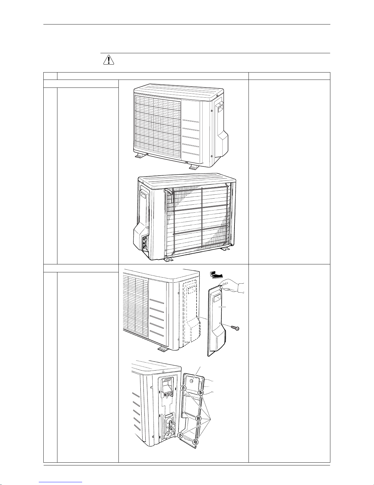
1. External appearance
Take care not to cut your
finger by the fins of the
outdoor heat exchanger.
2. Remove the panels.
The stop valve cover is
united with the shield plate.
When reassembling, make
sure to fit the 5 hooks.
1
Remove the screw of
the stop valve cover.
Pull down the stop
valve cover and remove
it.
DAIKIN
INVERTER
(R7186)
(R3236)
Stop
valve
cover
(R7188)
Shield plate
Hook
(R7189)
Si011083 Removal of Outer Panels / Fan Motor
Removal Procedure 3
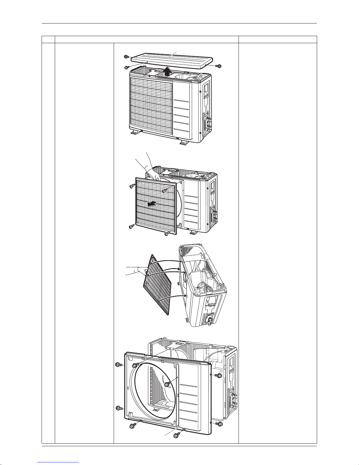
2
Remove the 3 screws
and remove the top
panel.
3
Remove the 4 screws
and remove the
discharge grille.
The discharge grille has 4
hooks.
4
Remove the 8 screws
and remove the front
panel.
Step Procedure Points
DAIKIN
INVERTER
Top panel
(R8290)
DAIKIN
INVERTER
(R8291)
(R8292)
DAIKIN
INVERTER
(R8294)
Front panel
 Loading...