


OPERATION AND INSTALLATION
INSTRUCTIONS MANUAL
DUCTED AIR-CONDITIONING UNIT
Unit Model:
Indoor unit
FDM24PEV1K
FDM30PEV1K
FDM36PEV1K
FDM42PEV1K
FDM48PEV1K
FDYM24PEV1K
FDYM30PEV1K
FDYM36PEV1K
FDYM42PEV1K
FDYM48PEV1K
English
(7.0-14.0kW)
Outdoor unit
R24PEV1K
R30PEV1K
R36PEY1K
R42PEY1K
R48PEY1K
RY24PEV1K
RY30PEV1K
RY36PEY1K
RY42PEY1K
RY48PEY1K

User Notice
Ensure unified power supply for each indoor unit.
Never install wired controller in wet place or under sunlight directly.
Shielding twisted pair line must be adopted as signal line or wiring (communication) of
wired controller once the unit is installed in the place where there is electromagnetic
interference.
Make sure communication line is connected into correct port to avoid communication
error.
Never knock, throw or frequently disassemble the wired controller.
Never operate the wired controller with wet hand.

Contents
I
SAFETY PRECAUTIONS ....................................................................................................................... 2
II DISPLAYING PART ................................................................................................................................ 6
2.1 LCD Display of Wired Controller ............................................................................................................................................ 6
2.2 Instruction to LCD Display ..................................................................................................................................................... 7
III BUTTONS ............................................................................................................................................... 8
3.1 Silk Screen of Buttons ........................................................................................................................................................... 8
3.2 Instruction to Function of Buttons .......................................................................................................................................... 8
IV INSTALLATION OF WIRED CONTROLLER ................................................. ........................................ 9
V INSTRUCTION TO OPERATION .......................................................................................................... 10
5.1 On/Off .................................................................................................................................................................................. 10
5.2 Mode Setting ....................................................................................................................................................................... 10
5.3 Temperature Setting ............................................................................................................................................................ 11
5.4 Fan Speed Setting ............................................................................................................................................................... 11
5.5 Swing Control Function* ...................................................................................................................................................... 12
5.6 Timer Setting ....................................................................................................................................................................... 12
5.7 Air Exchange Setting* .......................................................................................................................................................... 14
5.8 Sleep Setting ....................................................................................................................................................................... 15
5.9 Turbo Function Setting ......................................................................................................................................................... 16
5.10 Save Function Setting ....................................................................................................................................................... 16
5.11 E-heater Setting* ............................................................................................................................................................... 18
5.12 Blow Function Setting ....................................................................................................................................................... 19
5.13 Quiet Function Setting ....................................................................................................................................................... 20
5.14 Field Setting.............. ......................................................................................................................................................... 20
5.15 Other Functions ................................................................................................................................................................. 21
V I ERROR DISPLAY ................................................................................................................................. 22
II UNIT FUNCTION .................................................................................................................................. 23
V
7.1 Setting of Double Indoor Room Sensors ............................................................................................................................. 23
7.2 Checking of Outdoor Ambient Temperature ........................................................................................................................ 23
7.3 Fresh Air Control ................................................................................................................................................................. 24
7.4 The head of delivery of the condensate drainage pump* .................................................................................................... 24
VIII INSTALLATION INSTRUCTIONS ................... .................................................................................... 25
8.1 Dimensions of Indoor Unit ................................................................................................................................................... 25
8.2 Dimensions of Outdoor Unit ................................................................................................................................................ 27
8.3 Precautions on Installation of Outdoor Unit ......................................................................................................................... 27
8.4 Precautions on Installation of Indoor Unit ............................................................................................................................ 28
8.5 Level Check of the Indoor Unit ............................................................................................................................................ 29
8.6 Installation of Rectangular Air Pipe ..................................................................................................................................... 29
8.7 Installation of Drainage Pipeline .......................................................................................................................................... 30
8.8 Testing of Drainage System ................................................................................................................................................. 3
8.9 Selection of the Refrigerant Pipe ........................................................................................................................................ 31
8.10 Connection of the Refrigerant Pipe ................................................................................................................................... 31
8.11 Installation of Protective Layer of Pipe ..................................................................................................... 33
8.12 Position and Method of Installing Wired Controller ............................................................................................................ 33
8.13 Connection of Signal Line of Wired Controller ................................................................................................................... 34
8.14 Electri Installation ................................... ....................................................................................................................... 35
8.15 Power Cable Connection .................................................................................................................................................. 36
8.16 Cable Connecting Diagram .................................................................................................................................... 36...........
8.17 Troubleshooting and Maintenance ..................................................................................................................................... 39
8.18 Routine Maintenance ........................................................................................................................................................ 39
c..
.
the Refrigerant
IX SPECIFICATIONS ................................................................................................................................ 4
1
2
English
Notes: The functions with * are reserved for other models and are not applicable
for the models listed in this manual.
1
I SAFETY PRECAUTIONS
To gain full advantage of the air conditioner’s functions and to avoid malfunction due to mishandling, we
recommend that you read this instruction manual carefully before use.
This air conditioner is classified under “appliances not accessible to the general public”.
Please read these “SAFETY PRECAUTIONS” carefully before installing air conditioning equipment and be
sure to install it correctly.
After completing installation, conduct a trial operation to check for faults and explain to the user how to
operate the air conditioner and take care of it with the aid of the operation manual. Ask the user to store
the installation manual along with the operation manual for future reference.
The precautions described herein are classified as WARNING and CAUTION. They both contain important
information regarding safety. Be sure to observe all precautions without fail.
Meaning of WARNING and CAUTION notices.
WARNING .......... Failure to follow these instructions properly may result in personal injury or loss of life.
CAUTION ........... Failure to observe these instructions properly may result in property damage or
personal injury, which may be serious depending on the circumstances.
After reading, keep this manual in a convenient place so that you can refer to it whenever necessary. If the
equipment is transferred to a new user, be sure also to hand over the manual.
WARNING
• Be aware that prolonged, direct exposure to cool or warm air from the air conditioner, or to air that is too
cool or too warm can be harmful to your physical condition and health.
• When the air conditioner is malfunctioning (giving off a burning odour, etc.) turn off power supply to the unit
and contact our local dealer.
Continued operation under such circumstances may result in a failure, electric shocks or fi re hazards.
• Consult our local dealer about installation work.
Doing the work yourself may result in water leakage, electric shocks or fi re hazards.
• Consult our local dealer regarding modification, repair and maintenance of the air conditioner.
Improper workmanship may result in water leakage, electric shocks or fi re hazards.
• Do not place objects, including rods, your fingers, etc., in the air inlet or outlet.
Injury may result due to contact with the air conditioner’s highspeed fan blades.
ware of fire in case of refrigerant leakage.
• Be
If the air conditioner is not operating correctly, i.e. not generating cool or warm air, refrigerant leakage could
be the cause.
Consult our dealer for assistance.
The refrigerant within the air conditioner is safe and normally does not leak.
However, in the event of a leakage, contact with a naked burner, heater or cooker may result in generation
of noxious gas.
Do not use the air conditioner until a qualified service person confirms that the leakage has been
repaired.
• Consult our local dealer regarding what to do in case of refrigerant leakage.
When the air conditioner is to be installed in a small room, it is necessary to take proper measures so that
the amount of any leaked refrigerant does not exceed the concentration limit in the event of a leakage.
Otherwise, this may lead to an accident due to oxygen depletion.
• Contact professional personnel about attachment of accessories and be sure to use only accessories
specified by the manufacturer.
If a defect results from your own workmanship, it may result in water leaks, electric shock or fi re.
• Consult our local dealer regarding relocation and reinstallation of the air conditioner.
Improper installation work may result in leakage, electric shocks or fi re hazards.
• Be sure to use fuses with the correct ampere reading.
Do not use improper fuses, copper or other wires as a substitute, as this may result in electric shock, fi re,
injury or damage to the unit.
any longer
2
English

• Be sure to earth the unit.
Do not earth the unit to a utility pipe, lightning conductor or telephone earth lead. Imperfect earthing may
result in electric shocks or fi re.
A high surge current from lightning or other sources may cause damage to the air conditioner.
• Be sure to install an earth leakage breaker.
Failure to install an earth leakage breaker may result in electric shocks or fi re.
• Consult the dealer if the air conditioner submerges owing to a natural disaster, such as a flood or typhoon.
Do not operate the air conditioner in that case, or otherwise a malfunction, electric shock, or fire may result.
• Do not start or stop operating the air conditioner with the power supply breaker turned ON or OFF.
Otherwise, fire or water leakage may result. Furthermore, the fan will rotate abruptly if power failure compensation is enabled, which may result in injury.
Do not use the product in the atmosphere contaminated with oil vapor, such as cooking oil or machine oil vapor.
•
Oil vapor may cause crack damage, electric shocks, or fi re.
• Do not use the product in places with excessive oily smoke, such as cooking rooms, or in places with
flammable gas, corrosive gas, or metal dust.
Using the product in such places may cause fire or product failures.
• Do not use flammable materials (e.g., hairspray or insecticide) near the product.
Do not clean the product with organic solvents such as paint thinner.
The use of organic solvents may cause crack damage to the product, electric shocks, or fi re.
• Be sure to use a dedicated power supply for the air conditioner.
The use of any other power supply may cause heat generation, fire, or product failures.
• Ask our dealer or qualified personnel to carry out installation work.
Do not attempt to install the air conditioner yourself. Improper installation may result in water leakage,
electric shocks or fi re.
• Install the air conditioner in accordance with the instructions in this installation manual.
Improper installation may result in water leakage, electric shocks or fi re.
• Be sure to use only the specified accessories and parts for installation work.
Failure to use the specified parts may result in the unit falling, water leakage, electric shocks or fi re.
• Install the air conditioner on a foundation strong enough to withstand the weight of the unit.
A foundation of insufficient strength may result in the equipment falling and causing injury.
• Carry out the specified installation work after taking into account strong winds, typhoons or earthquakes.
Failure to do so during installation work may result in the unit falling and causing accidents.
• Make sure that a separate power supply circuit is provided for this unit and that all electrical work is carried
out by qualified personnel according to local laws and regulations and this installation manual.
An insufficient power supply capacity or improper electrical construction may lead to electric shocks or fi re.
• Make sure that all wiring is secured, the specified wires are used, and that there is no strain on the terminal
connections or wires.
Improper connections or securing of wires may result in abnormal heat build-up or fi re.
• When wiring the power supply and connecting the wiring between the indoor and outdoor units, position the
wires so that the control box lid can be securely fastened.
Improper positioning of the control box lid may result in electric shocks, fire or overheating terminals.
• If refrigerant gas leaks during installation, ventilate the area immediately.
Toxic gas may be produced if the refrigerant comes into contact with fi re.
• After completing installation, check for refrigerant gas leakage.
Toxic gas may be produced if the refrigerant gas leaks into the room and comes into contact with a source
of fire, such as a fan heater, stove or cooker.
• Be sure to cut off the power supply before touching any electrical parts.
English
3

CAUTION
• Do not use the air conditioner for purposes other than those for which it is intended.
Do not use the air conditioner for cooling precision instruments, food, plants, animals or works of art as this
may adversely affect the performance, quality and/or longevity of the object concerned.
• Do not remove the outdoor unit’s fan guard.
The guard protects against the unit’s high speed fan, which may cause injury.
• Do not place objects that are susceptible to moisture directly beneath the indoor or outdoor units.
Under certain conditions, condensation on the main unit or refrigerant pipes, air filter dirt or drain blockage
may cause dripping, resulting in fouling or failure of the object concerned.
• To avoid oxygen depletion, ensure that the room is adequately ventilated if equipment such as a burner is
used together with the air conditioner.
• After prolonged use, check the unit stand and its mounting situation
If left in a damaged condition, the unit may fall and cause injury.
• Do not place flammable sprays or operate spray containers near the unit as this may result in fi re.
• Before cleaning, be sure to stop unit operation, turn the breaker off or remove the power cord.
Otherwise, an electric shock and injury may result.
• To avoid electric shocks, do not operate with wet hands.
• Do not place appliances that produce naked flames in places exposed to the air flow from the unit as this
may impair combustion of the burner.
• Do not place heaters directly below the unit, as resulting heat can cause deformation.
• Do not allow a child to mount on the outdoor unit or avoid placing any object on it.
Falling or tumbling may result in injury.
• Do not block air inlets or outlets.
Impaired air flow may result in insufficient performance or trouble.
• Be sure that children, plants or animals are not exposed directly to airflow from the unit, as adverse effects
may ensue.
• Do not wash the air conditioner with water, as this may result in electric shocks or fi re.
• Do not install the air conditioner at any place where there is a danger of flammable gas leakage.
In the event of a gas leakage, build-up of gas near the air conditioner may result in fi re hazards.
• Do not put flammable containers, such as spray cans, within 1 m from the air outlet.
The containers may explode because the warm air output of the indoor or outdoor unit will affect them.
• Arrange the drain to ensure complete drainage.
If proper drainage from the outdoor drain pipe does not occur during air conditioner operation, there could
be a blockage due to dirt and debris build-up in the pipe.
This may result in a water leakage from the indoor unit.
Under these circumstances, stop air conditioner operation and consult your dealer for assistance.
• The appliance is not intended for use by unattended young children or infi rm persons.
Impairment of bodily functions and harm to health may result.
• Children should be supervised to ensure that they do not play with the unit or its remote controller.
Accidental operation by a child may result in impairment of bodily functions and harm health.
• Do not let children play on or around the outdoor unit.
If they touch the unit carelessly, injury may be caused.
• Consult our dealer regarding cleaning the inside of the air conditioner.
Improper cleaning may cause breakage of plastic parts, water leakage and other damage as well as
electric shocks.
• To avoid injury, do not touch the air inlet or aluminium fins of the unit.
Do not place objects in direct proximity of the outdoor unit and do not let leaves and other debris accumulate
•
around the unit.
Leaves are a hotbed for small animals which can enter the unit. Once get in the unit, such animals can
cause malfunctions, smoke or fire when making contact with electrical parts.
• Never touch the internal parts of the controller.
Do not remove the front panel. Touching certain internal parts will cause electric shocks and damage to the
unit. Please consult our dealer about checking and adjustment of internal parts.
• Do not leave the remote controller wherever there is a risk of wetting.
If water gets into the remote controller there is a risk of electrical leakage and damage to electronic components.
4
English

• Watch your steps at the time of taking out or put back the air filter for cleaning or inspection.
High-place work is required, to which utmost attention must be paid.
If the scaffold is unstable, you may fall or topple down, thus causing injury.
• While following the instructions in this installation manual, install drain piping to ensure proper drainage and
insulate piping to prevent condensation.
Improper drain piping may result in indoor water leakage and property damage.
• Install the indoor and outdoor units, power cord and connecting wires at least 1 meter away from televisions
or radios to prevent picture interference and noise.
(Depending on the incoming signal strength, a distance of 1 meter may not be sufficient to eliminate noise.)
• Remote controller (wireless) transmitting distance can be shorter than expected in rooms with electronic
fluorescent lamps (inverter or rapid start types).
Install the indoor unit as far away from fluorescent lamps as possible.
• Do not install the air conditioner in the following locations:
1. Where there is a high concentration of mineral oil spray or vapour (e.g. a kitchen).
Plastic parts will deteriorate, parts may fall off and water leakage could result.
2. Where corrosive gas, such as sulphurous acid gas, is produced.
Corroding of copper pipes or soldered parts may result in refrigerant leakage.
3. Near machinery emitting electromagnetic radiation.
Electromagnetic radiation may disturb the operation of the control system and result in a malfunction of
the unit.
4. Where flammable gas may leak, where there is carbon fibre or ignitable dust suspensions in the air, or
where volatile flammables such as paint thinner or gasoline are handled.
Operating the unit in such conditions may result in fi re.
English
5
II DISPLAYING PART
Fig.2.1 Outline of wired controller
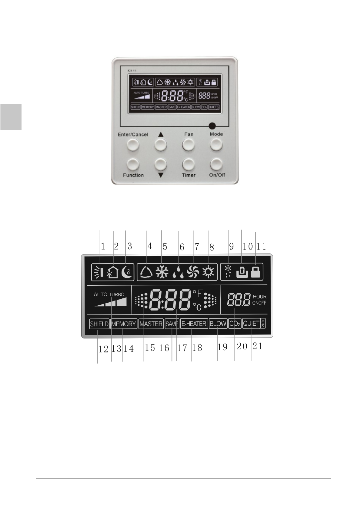
2.1 LCD Display of Wired Controller
Fig.2.2 LCD display
6
English
2.2 Instruction to LCD Display
No. Description Instruction to Displaying Contents
1 Swing* Swing function
2 Air* Air exchange function
3 Sleep Sleeping states
4 Running mode Each kind of running mode of indoor unit (auto mode)
5 Cooling Cooling mode
6 Dry Dry mode
7 Fan Fan
8 Heating Heating mode
9 Defrost Defrosting state
Gate-control
10
card*
11 Lock Lock state
12 Shield
13 Turbo Turbo function state
14 Memory
15 Twinkle Flicking when unit is on without operation of buttons
16 Save Energy-saving state
17 Temperature Ambient/setting temperature value
18 E-Heater E-HEAT display means electric-heater is available
19 Blow Blow mark
20 Timer Timer-displayed location
21 Quiet Quiet state (two types: quiet and auto quiet)
Notes:
The functions with * are reserved for other models and are not applicable
for the models listed in this manual.
*
Gate control
Shielding state (buttons, temperature, on/off, mode or save is shielded by
long-distance monitoring
Memory state (Indoor unit resumes original setting state after power failure and
then power recovery)
ER
English
Table.2.1
7
III BUTTONS
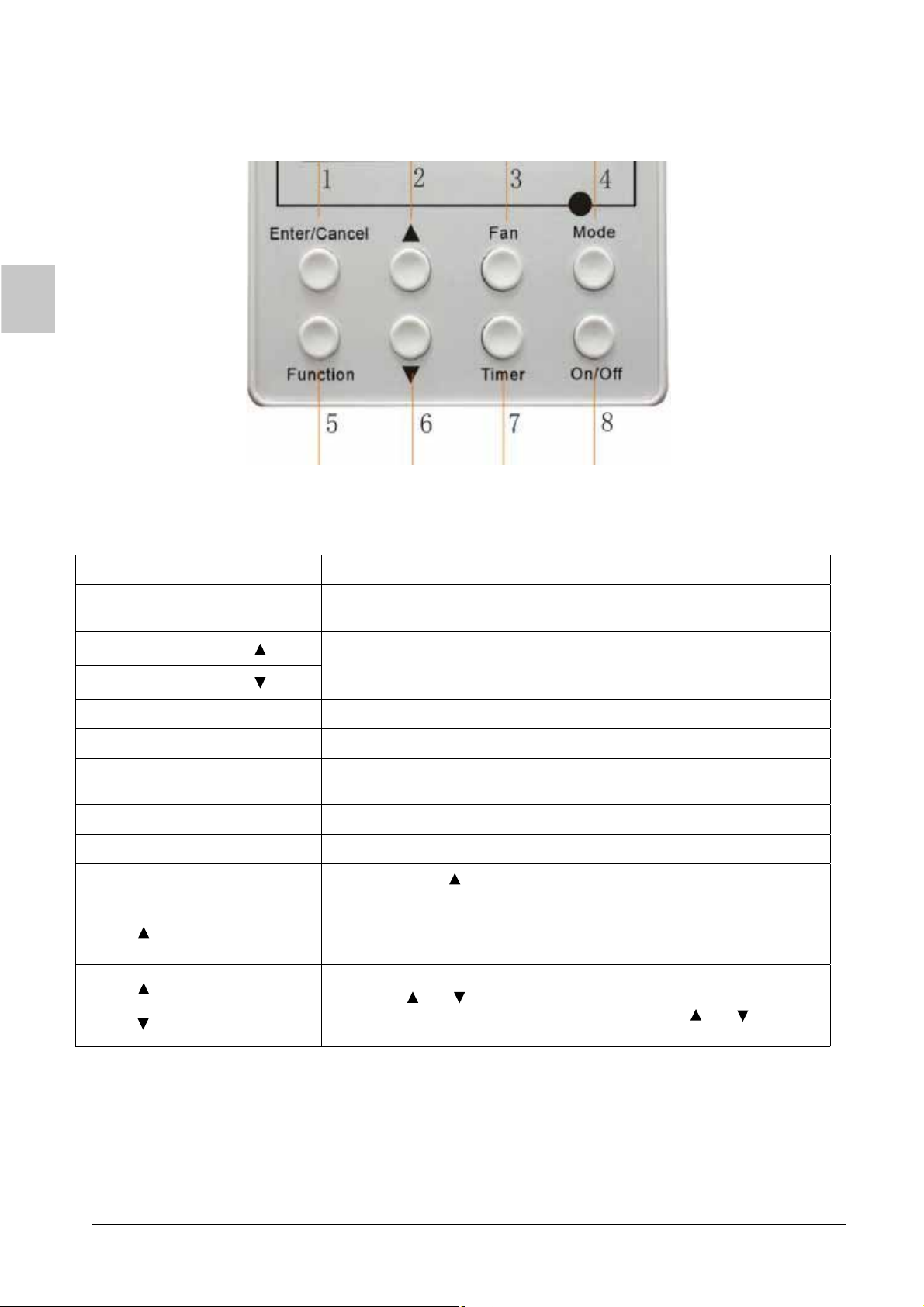
3.1 Silk Screen of Buttons
Fig.3.1 Silk screen of buttons
3.2 Instruction to Function of Buttons
No. Description Function of Button
1 Enter/Cancel
2
6
3 Fan Setting of high/middle/low/auto fan speed
4 Mode Setting of cooling/heating/fan/dry mode of indoor unit
5 Function
7 Timer Timer setting
8 On/off Turn on/off indoor unit
4 Mode
and
2
2
and
6
Memory
function
Lock
(1) Function selection and canceling;
(2) Press it for 5s to enquiry the outdoor ambient temperature.
(1) Running temperature setting of indoor unit, range :16 ∼ 30°C
(2) Timer setting, range:0.5-24hr
(3) Switchover between quiet/auto quiet
Switchover among the functions of air/sleep/turbo/save/E-heater/blow/
quiet
Press and for 5s under off-state of the unit to enter/cancel key
Mode
memory function (If memory is set, indoor unit will resume original
setting state after power failue and then power recovery. If not, indoor
unit is defaulted to be off after power recovery. Memory function is
defaulted to be off before outgoing.)
Upon startup of the unit without malfunction or under off-state of the
unit, press and at the same time for 5s into lock state. In this case,
any other buttons won’t respond the press. Repress and for 5s to
quit lock state.
8
Table.3.1
English
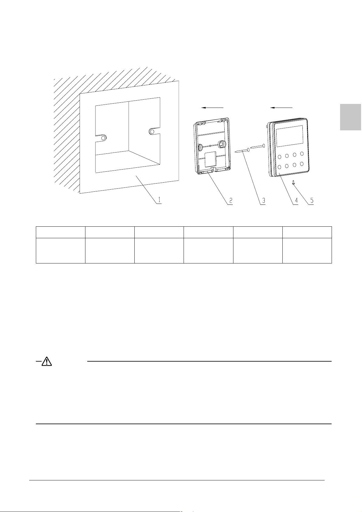
IV INSTALLATION OF WIRED CONTROLLER
Fig.4.1 Sketch for Installation of Wired Controller
No. 1 2 3 4 5
Socket’s base
Description
Fig.4.1: Sketch for Installation of Wired Controller. Pay attention to the following items during the installation of
wired controller:
1. Cut off power supply before installation. It
2. Pull out 4-core twisted pair line in mounting hole and then make it through the rectangle hole at the
back of controller’s soleplate.
3. Joint the controller’s soleplate on wall face and then fix it in mounting hole with screws M4X25.
4. Insert the 4-core twisted pair into controller’s slot through rectangle hole and buckle the front panel and
soleplate of controller together.
5. At last, fix the controller’s front panel and soleplate with screws ST2.2X6.5.
CAUTION
During connection of wirings, pay special attention to the following items to avoid interference of electromagnetism to unit and even failure of it.
1. To ensure normal communication of the unit, signal line and wiring (communication) of wired controller
should separate from power cord and indoor/outdoor connection lines. The min distance between them
should be 20cm.
2. If the unit is installed at the place where there is interference of electromagnetism, signal line and wiring
(communication) of wired controller must be shielding twisted pair lines.
box installed in
the wall
Soleplate of
controller
is prohibited to perform the whole procedure with electricity.
Screw M4X25
Front panel of
controller
.
Screw
ST2.2X6.5
English
9
V INSTRUCTION TO OPERATION
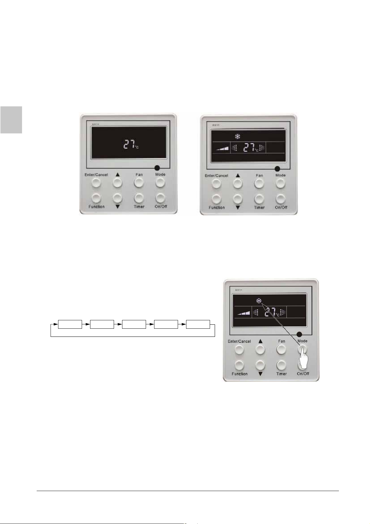
5.1 On/Off
Press On/Off button to turn on the unit.
Repress this button to turn off the unit.
Note:The state shown in Fig.5.1 indicates off-state of the unit after energization. The state shown in Fig.5.2
indicates on-state of the unit after energization.
Fig.5.1 Off-state of the unit Fig.5.2 On-state of the unit
5.2 Mode Setting
Under on-state of the unit, press Mode button to switch the operation modes as the following sequence:
Auto Cooling Dry Fan Heating
10
English
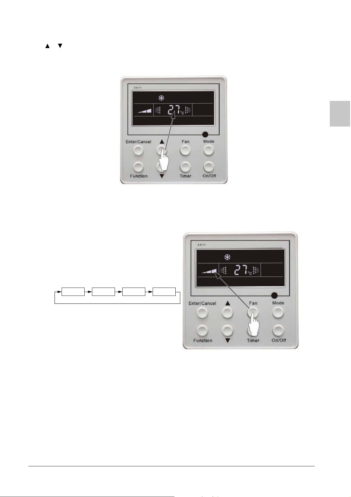
5.3 Temperature Setting
Press or button for increase or decrease of setting temperature under on-state of the unit. If press either
of them continuously, temperature will be increased or decreased by 1°C every 0.5s.
In Cooling, Dry, Fan and Heating mode, temperature setting range is 16 ∼ 30°C.
In Auto mode, the setting temperature is un-adjustable.
As shown in Fig.5.3
Fig.5.3
5.4 Fan Speed Setting
Press button, fan speed of indoor unit will change as below:
Fan
As shown in Fig.5.4
Auto Low Middle High
Fig.5.4
English
11
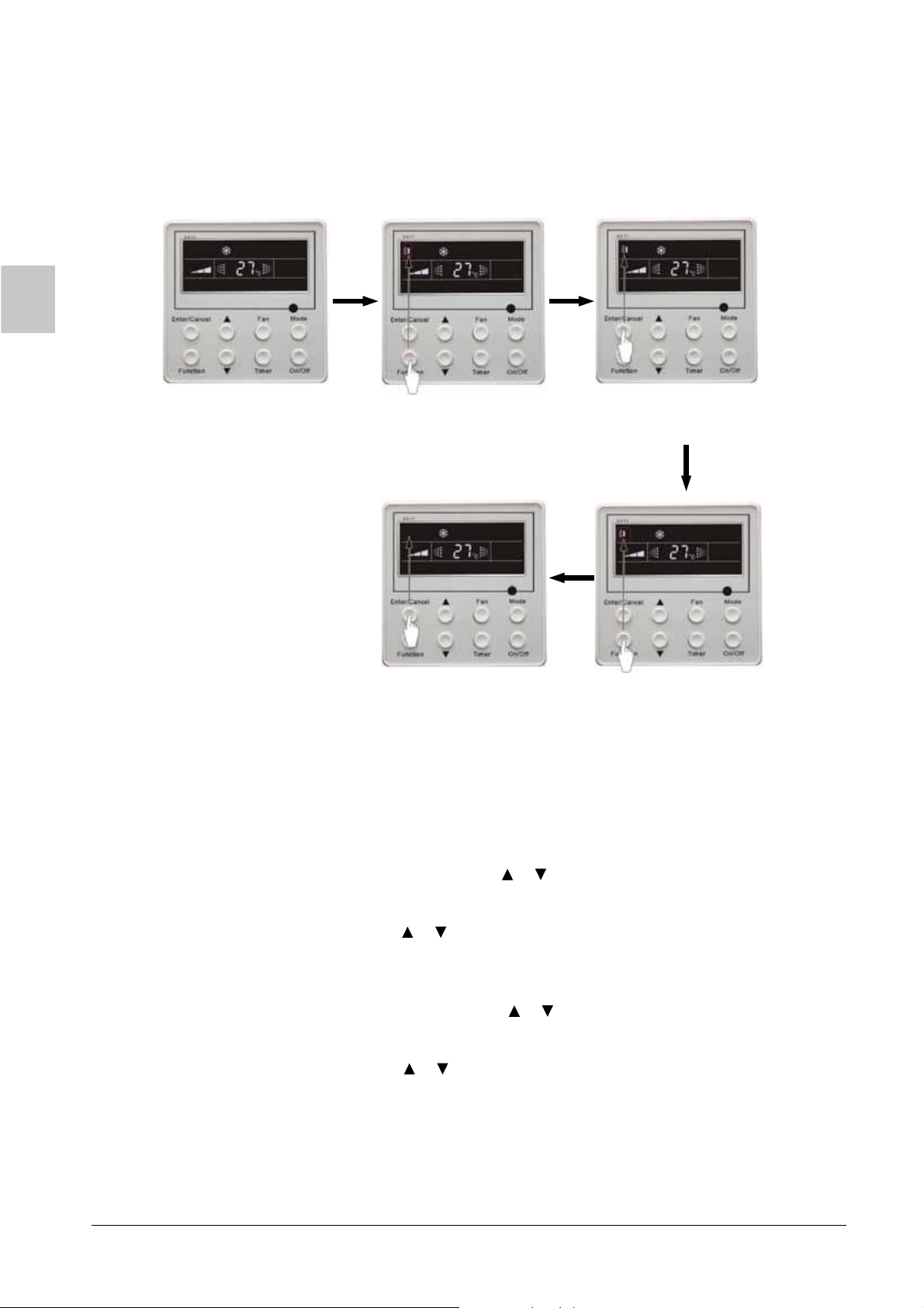
5.5 Swing Control Function *
Under on-state of unit, press Function button till the unit enters swing control function and then press Enter/
Cancel button to turn on s control function.
During swing function, press Function button till the unit enters swing control function and then press Enter/
Cancel button to cancel swing control function.
Swing control function setting is shown in Fig.5.5
wing
Turn on the unit, without
turning on swing function
Press “Function” button
into swing function
Press “Enter/Cancel” button Press “Function” button
to turn off swing function into swing function
Press “Enter/Cancel” button
to turn on swing function
Fig.5.5
5.6 Timer Setting
Timer button to set timer off of the unit. Under off-state of the unit, press Press
on of the unit in the same way.
Timer on setting: Under off-state of the unit without timer setting, if Timer button is pressed, LCD will display
xx. Hour, ON blinking. In this case, press or button to adjust timer on and then press
Timer to confi rm. If Mode button is pressed before pressing Timer button to confi rm, timer
mode will be switched to timer off setting mode. In this case, LCD displays xx. Hour, OFF
blinking. In this case, press or button to adjust timer off and then press Timer to confi rm.
When LCD displays xx. Hour On Off, xx. Hour means time of timer on, but time of timer off
won’t be displayed.
Timer off setting: Under on state of the unit without timer setting, if Timer button is pressed, LCD will display
-
xx. Hour, OFF blinking. In this case, press or button to adjust timer on and then press
Timer to confi rm. If Mode button is pressed before pressing Timer button to confi rm, timer
mode will be switched to timer on setting mode. In this case, LCD displays xx. Hour, ON
blinking. In this case, press
or button to adjust timer on and then press Timer button to
confirm. When LCD displays xx. Hour On Off, xx. Hour means time of timer off, but time of
timer on won’t be displayed.
Cancel timer: After setting of timer, if Timer button is pressed, LCD won’t display xx. Hour so that timer setting
is canceled.
Timer button to set timer
12
English

Timer off setting under on state of the unit is shown as Fig.5.6
-
Turn on the unit, without
setting timer
Press “Timer” to confirm
timer setting
Press “Timer” to set Press “ ” or “ ”
button to adjust time
Press “ ” or “ ”
button to adjust time
Press “Mode” button into
timer on setting interface
Fig.5.6 Timer setting under on-state of the unit
Timer range: 0.5-24hr. Every press of
or button will make setting time increased or decreased by 0.5hr.
If press either of them continuously, setting time will automatically increase/decrease by 0.5hr
every 0.5s.
Note:
1. If both timer on and timer off are set in on-state, the wired controller only displays time of timer off.
If both of them are set in unit off-state, only time of timer on is displayed.
2. Timer on in on-state is timed from the time of unit off and timer off in unit off-state is timed
from
the time of unit on.
English
13

5.7 Air Exchange Setting*
Tu r n n air exchange function:
-o
Under on-state of the unit, press
blinks). AIR 1 displayed at the ambient temperature-displayed location (888) is defaulted
(the last type of AIR will be displayed after adjustment). Press
e
xchange type. Press
turning on
There are 10 types of ir xchange, but only 1-2 types are for wireless remote control. Refer to the following
ae
this function, the air mark shows.
Enter/Cancel button to turn on/off air exchange function. After
details:
1 —— The unit continuously runs for 60min, and fresh air valve opens for 6 min.
2 —— The unit continuously runs for 60min, and fresh air valve opens for 12 min.
3 —— The unit continuously runs for 60min, and fresh air valve opens for 18 min.
4 —— The unit continuously runs for 60min, and fresh air valve opens for 24 min.
5 —— The unit continuously runs for 60min, and fresh air valve opens for 30 min.
6 —— The unit continuously runs for 60min, and fresh air valve opens for 36 min.
7 —— The unit continuously runs for 60min, and fresh air valve opens for 42 min.
8 —— The unit continuously runs for 60min, and fresh air valve opens for 48 min.
9 —— The unit continuously runs for 60min, and fresh air valve opens for 54 min.
10 —— The unit continuously runs for 60min, and fresh air valve always opens.
Turn off air exchange function:
-
During air exchange function, press
In this case, air mark is blinking, and then press
this function. Air mark will subsequently disappear.
Air exchange setting is shown as Fig.5.7:
Function button into this function setting (Air mark
or button to adjust air
Function button into air exchange function.
Enter/Cancel button to turn off
Turn on the unit, without
ning on air exchange tur
function
Press “Enter/Cancel” button Press “Function” button Press “Enter/Cancel” button
to turn off air exchange function to turn on air exchange
Press “Function” button
into air exchange function
into air exchange function
Press “ ” or “ ”
button to adjust the type of air
exchange
function
Fig.5.7 Air exchange device
Note:In air exchange mode, press button or there is no any operation within 5s after the last button
operation, the system will quit from air exchange setting ,and current setting data won’t be
“Function”
memoried.
14
English

5.8 Sleep Setting
Sleep on: Press Function button under on-state of the unit into Sleep function and then press Enter/Cancel
button to turn on sleeping function.
Sleep off: During sleep on state, press Function button into leep function and then press Enter/Cancel
button to turn off this function.
Sleep setting is shown as Fig.5.8:
S
Turn on the unit, without
turning on sleep function
Press “Function” button
into sleep function
Press “Enter/Cancel” button
to turn off sleep function
Press “Enter/Cancel” button
to turn on sleep function
Press “Function” button
into sleep function
Fig.5.8 Sleep setting
Sleep ed after power failure and then power recovery. There is no sleep function in fan and auto
setting is clear
mode.
Note:In cooling and dry mode, if the unit with sleep function has run for 1 hour, the preset temperature will be
increased by 1°C and 1°C in another 1 hour. After that, the unit will run at this temperature. In heating
mode, if the unit with sleep function has run for 1 hour, the preset temperature will be decreased by 1°C
and 1°C in another 1 hour. After that, the unit will run at this temperature.
English
15

5.9 Turbo Function Setting
Turbo function: The unit at high fan speed can realize quick cooling or heating so that room temperature can
quickly approach setting temperature.
In cooling or heating mode, press Function button till the unit enters turbo function and then
press Enter/Cancel button to turn on turbo function.
During turbo function, press Function button till the unit enters turbo function and then press
Enter/Cancel button to cancel turbo function.
Turbo function setting is shown in Fig.5.9:
Turn on the unit, without
turning on urbo function
t
Press “Function” button
into turbo function
Press “Enter/Cancel” button
to turn off turbo function
Press “Enter/Cancel” button
to turn on turbo function
Press “Function” button
into turbo function
Fig.5.9 Turbo Function Setting
Note:
1. Turbo function will be turned off after power failure and then recovery. In dry, fan and auto mode, turbo
function can not be set and T mark won’t be displayed.
URBO
2. Turbo function will be automatically canceled after setting of quiet function.
5.10 Save Function Setting
Energy Saving Function: Energy saving result that the air conditioner runs in smaller temperature range is
realized by setting lower limited value of setting temperature in cooling or dry mode
and upper limited value in heating mode.
Energy Saving Setting for Cooling
Under on-state and in cooling or dry mode of the unit, press Function button into energy saving function,
SAVE blinking. Press
After that press Enter/Cancel button to turn on energy saving function for cooling.
Energy Saving Setting for Heating
Under on state and in heating mode of the unit, press Function button into energy saving function, SAVE
blinking. Press Mode button into energy saving function for heating and then press or button to adjust
upper limited value of setting temperature in heating mode. After that, press Enter/Cancel button to turn on
energy saving function for heating.
16
or button to adjust lower limited value of setting temperature in cooling mode.
English

After energy saving function is turned on, press Function button into energy saving function and press
Enter/Cancel to cancel this function.
button
The energy saving setting is shown in the Fig.5.10.
Turn on the unit, without
turning on save function
Press “Enter/Cancel” button
to turn off save function
Press “Function” button
into cooling save function
Press “ ” or “ ”
button to change the upper
limit of heating
Press “ ” or “ ”
button to change the lower
limit of cooling
Press “Mode” button into
heating save function
Fig.5.10 Energy Saving Setting
Note:
1. In auto running mode with save function on, the unit will forcibly quit auto running mode and change to
current
2. In save mode, if button is pressed or there is not any operation within 5s after the last button
operation mode. After setting of SAVE, sleep function will be canceled.
Function
operation, the system will quit from save function setting and current data won’t be memorized.
3. After power failure and then recovery, save function setting will be memorized.
4. The lower limited value in cooling mode is 16°C and the upper limited value in heating mode is 30°C.
5. After save setting, if the setting temperature is out of the range in the mode, the limited value will prevail.
English
17

5.11 E-heater etting *
S
E-heater: In heating mode, E-heater is allowed to be turned on for improvement of effi ciency.
the
If heating mode is turned on by button operation, auxiliary electric heating function will be automatically turned on.
Press Function button in heating mode into auxiliary electric heating function, E-HEATER blinking,
and press Enter/Cancel button to turn on this function. In this case, E-HEATER will be displayed,
which means E-heater is allowed to be turned on.
If auxiliary electric heating function is on, press Function button to confirm or press Enter/Cancel
button to cancel. In this case, E-HEATER won’t be displayed, which means E-heater is prohibited to
be turned on.
The setting of this function is shown as Fig.5.11 below:
Auxiliary electric heating
function will be automatically
turn on under heating mode
Press “Function” button
into E-Heater function
Press “Enter/Cancel” button
to turn off E-Heater function
Press “Enter/Cancel” button
to turn on E-Heater function
Press “Function” button
into E-Heater function
Fig.5.11 Auxiliary Electric Heating Function Setting
Note:
E-heater can not be set in cooling, dry and fan mode, E-HEATER mark won’t be displayed. The setting
shown in Fig.5.11. is
18
English

5.12 Blow Function Setting
Blow function: After the unit is turned off, water in evaporator of indoor unit will be automatically evaporated to
avoid mildew.
In cooling and dry mode, press Function button till the unit enters dry function, BLOW blinking,
and then press Enter/Cancel button to turn on this function.
In blow mode, press Function button till the unit enters blow function and then press Enter/
Cancel button to cancel this function.
Blow function setting is shown in Fig.5.12
Turn on the unit, without
turning on blow function
Press “Function” button
into blow function
Press “Enter/Cancel” button
to turn off blow function
Press “Enter/Cancel” button
to turn on blow function
Press “Function” button
into blow function
Fig.5.12 Blow function setting
Note:
1. After setting blow function, turn off the unit by pressing On/Off button or remote controller, indoor fan will
run at low fan speed for 10 min. (BLOW shows). Meanwhile, if blow function is canceled, indoor fan will be
turned off directly.
2. There is no BLOW function in fan or heating mode.
English
19

5.13 Quiet Function Setting
Quiet function consists of two : quiet and auto quiet.
Press Function button till the unit enters quiet function setting state, Q or A QUIET mark blinks. In this
case, press
or button to switch between Q and AUTO QUIET and then press Enter/Cancel button to
types
UIET UTO
UIET
turn on this function.
In quiet mode, press Function button till the unit enters quiet function. In this case, Q or AUTO QUIET icon
UIET
blinks and then press Enter/Cancel button to cancel this function.
Quiet function setting is shown in Fig.5.13
Turn on the unit, without
turning on quiet function
Press “Function” button
into quiet function
Press “ ” or “ ”
button switch to auto quiet
function
Press “Enter/Cancel” button
to turn off the quiet function
Press “Function” button
into quiet function
Press “Enter/Cancel” button
to turn on the type of quiet
function
Fig.5.13 Quiet function setting
Note:
1. During quiet function, fan speed is un-adjustable.
2. When turning on auto quiet function, the unit will enter quiet running state according to temperature
difference between room temperature and setting temperature. In this case, fan speed is adjustable. If
temperature difference between room temperature and setting temperature ≥ 4°C, fan will keep its
current speed; if 2°C ≤ temperature difference ≤ 3°C ; fan speed will be reduce one grade ,but if it is at
min. grade, it is un-adjustable.; if temperature difference ≤ 1°C, fan speed will be at min.
3. In auto quiet mode, fan speed can not be raised but reduced. If high fan speed is manually adjusted,
auto quiet mode will quit.
4. There is not auto quiet function in fan or dry mode. Quiet off is default after power failure and then
power recovery.
5. If quite function is set, turbo function will be canceled.
5.14 Field Setting
Under off state of the unit, press Function and Timer buttons continuously for 5s into debugging menu. Press
Mode button to adjust the setting items and or button to set the actual value.
-
20
English

5.14.1 Ambient Temperature Sensor Setting
In field mode, press Mode button to adjust the temperature displayed location displaying 00, and press
5.14.2 Three Grades of Speed for Indoor Fan
In field setting mode, press Mode button to adjust the temperature displayed location displaying 01 and press
Three low grades indicate high, medium and low grades and 3 high grades indicate super-high, high and
medium grades.
Press Enter/Cancel button to save the setting and quit after setting. If there is not any operation within 20s
after the system responds the latest button operation in this interface, the system will quit this menu and
display normal off state; meanwhile, current setting won’t be saved.
setting
or button to adjust setting state at timer displayed location. There are 3 types for selection:
(1) Indoor ambient temperature is that at return air inlet (01 is displayed at timer displayed location)
(2) Indoor ambient temperature is that at the place of wired controller (02 is displayed at timer
displayed location)
(3)
Return air inlet temperature sensor shall be selected for cooling, dry and fan modes and wired controller
temperature sensor shall be selected for heating and auto modes (03 is played at timer display location).
or button to adjust setting state at timer displayed location. There are 2 types for selection:
(1) 3 low grades (LCD displays 01)
(2) 3 high grades (LCD displays 02)
-
5.15 Other Functions
5.15.1 Lock Function
Upon startup of the unit without malfunction or under off state of the unit, press time for 5s till the wired controller enters lock state. In this case, LCD displays . After that, repress these two
uttons at the same time for 5s to quit lock-state.
b
Under lock state, any other buttons won’t give any response to the press.
-
-
and buttons at the same
5.15.2 Memory Function
Memory switchover: Under off state of the unit, press Mode and -
memory modes. During setting memory mode,
is not set, the unit will be under off-state after power failure and then power recovery.
Memory recovery: If memory mode has been set for wired controller, the wired controller after power failure
will resume its original running state upon power recovery.
Note:
1. It will take about 5s to save all the information. Please don’t cut down the power after content changed
in 5 second, or it may be fail to save the content.
5.15.
3 Enquiry of Outdoor Ambient Temperature
Under on off state of the unit, press Enter/Cancel button for 5s, outdoor ambient temperature will be
displayed at temperature displaying area after a sound of click. Pressing any button, this enquiry state will quit.
If there is not any operation for 20s, it will automatically quit.
Note:
1. This function will be shielded after energization of 12hr for some models of the units without outdoor
2. If malfunction of outdoor ambient sensor occurs, this function will be shielded in 12hr.
5.15.
Under off state of the unit, press Mode and
and Fahrenheit.
/-
ambient sensors. Please refer to Instruction for details.
4 Selection of Centigrade and Fahrenheit
-
at the same time for 5s, the LCD will switch between Centigrade
buttons at the same time for 5s to switch
MEMORY will be displayed. If this function
English
21

VI ERROR DISPLAY
If there is error during running of the system, LCD will
display error code at temperature–displayed location. Once many
error
s, error
multiple circuit systems, the circuit number of failed system will be
displayed before the colon (not for single circuit system).
If error occurs, please turn off the unit and ask professionals for help.
As shown in Fig.6.1, it means high pressure protection of system
2 under unit on.
Error code meaning:
Error code Error
codes will be displayed circularly. If there are
E1 High pressure protection of compressor
E2 Indoor anti-freezing protection
E3 Low pressure protection of compressor
E4 High discharge temperature protection of compressor
E5 Compressor overload protection
E6 Communication
E9 Water overfl ow protection
F0 Indoor unit ambient sensor error at air return opening
F1 Evaporator sensor error
F2 Condenser sensor error
F3 Outdoor unit ambient temperature sensor error
F4 Discharge temperature sensor error
F5 Ambient sensor error on Displayer (or LED board)
error
Fig.6.1
22
English

VII UNIT FUNCTION
Setting of Indoor Room Sensor and hecking of utdoor Ambient
Temperature
CO
7.1 Setting of Double Indoor Room Sensors
This series of ducted air-conditioning unit has two indoor room sensors. One is located at the air intake of the
indoor unit and the other one is located inside the wired controller.
User can select one from the two indoor room sensors on the basis of the engineering requirement.
(Refer to the section of wired controller instructions for detailed operation.)
Indoor Room Sensor A
Indoor Room Sensor B
Fig.7.1
7.2 Checking of Outdoor Ambient Temperature
The outdoor ambient temperature can be checked on the wired controller for the convenience of users
before going out. (Refer to the section of wired controller instructions for detailed operation.)
Indoor Side
Outdoor Side
Outdoor Room
Sensor
English
Fig.7.2
23

7.3 Fresh Air Control*
11-levels control can be realized for the amount of fresh air taken in. The function not only facilitates the health
of users, but also controls the electricity consumption loss because of taking in fresh air. This kind of control
can be carried out through the wire controller. The function can set at any time, goes into effect at any time,
and features very simple operation. (Refer to the section of wired controller instructions for detailed operation.)
d
Fresh Air
Air Intake Pipe Air Supply Pipe
Outdoor
Fresh Air
Indoor Side
Air Damper
Fig.7.3
7.4 The head of delivery of the condensate drainage pump*
It can reach 1.1m, so that the engineering
installation is very convenient and prompt.
Before starting up
the unit, please remove
all the sealing film on the
healthy fi lter block
Head of
Delivery of
Pump is
1100mm
or:
F
FDM24PEV1K
FDM30PEV1K
FDM36PEV1K
FDM42PEV1K
FDM48PEV1K
FDYM24PEV1K
FDYM30PEV1K
FDYM36PEV1K
FDYM42PEV1K
FDYM48PEV1K
Fig.7.4
24
English

VIII
INSTALLATION INSTRUCTIONS
8.1 Dimensions of Indoor Unit
Profile Dimensions of Indoor Unit & Outdoor Unit
8.1.1 Dimensions of Indoor Unit
G as pipe
Liquid pipe
A
C
D
E
G
Air Intake
26
B
I
Drainage Pipe
F
Air Supply
H
J
E l ectric Box
Item
Model
FDM24PEV1K
FDYM24PEV1K
FDM30PEV1K
FDYM30PEV1K
FDM36PEV1K
FDYM36PEV1K
FDM42PEV1K
FDYM42PEV1K
FDM48PEV1K
FDYM48PEV1K
Fig.8.1
For:
FDM24PEV1K FDYM24PEV1K
FDM30PEV1K FDYM30PEV1K
FDM36PEV1K FDYM36PEV1K
FDM42PEV1K FDYM42PEV1K
FDM48PEV1K FDYM48PEV1K
A B C D E F G H I J
1101 515 820 1159 1270 530 1002 160 235 268
1011 748 820 1115 1226 775 979 160 231 290
the Refrige-
rant Pipe
(Liquid Pipe)
φ
9.52
φ
12.7
the Refrige-
rant Pipe
(Gas Pipe)
φ
15.9
φ
19.05
Unit: mm
Drainage Pipe
(Outer Diameter ×
Wall Thickness)
φ
20 × 1.2
φ
20 × 1.2
English
25

8.1.2 Dimension Requirement of the Installation Space of Indoor Unit
Nut with
Washer
250 250
Nut Spring Washer
Fig.8.2
F
or:
FDM24PEV1K FDYM24PEV1K
FDM30PEV1K FDYM30PEV1K
FDM36PEV1K FDYM36PEV1K
FDM42PEV1K FDYM42PEV1K
FDM48PEV1K FDYM48PEV1K
WARNING
The height of installation for the indoor unit should be above 2.5m.
26
English

8.2 Dimensions of Outdoor Unit
8.2.1 Dimensions of Outdoor Unit
C
B
E
D
A
Fig.8.3
Unit: mm
Model
R42PEY1K
R24PEV1K R30PEV1K R36PEY1K RY42PEY1K
RY24PEV1K RY30PEV1K RY36PEY1K R48PEY1K
Item
A 1018 980 1018
RY48PEY1K
1107
B 412 427 412 440
C 695 790
110
8
40
0
D 572 610 572 631
E378 395 378 400
8.2.2 Dimension Requirement of the Installation Space of Outdoor Unit
1m
0.5m
0.5m
2m
0.5m
2m
0.5m
Fig.8.4
8.3 Precautions on Installation of Outdoor Unit
To ensure the unit in proper function, selection of installation location must be in accordance with following
principles:
(1) Outdoor unit shall be installed so that the air discharged by outdoor unit will not return and that suffi cient
space for repair shall be provided around the machine.
(2) The installation site must have good ventilation, so that the outdoor unit can take in and exhaust enough
air. Ensure that there is no obstacle for the air intake and exhaust of the outdoor unit. If there is any obstacle blocking the air intake or exhaust, remove it.
(3) Place of installation shall be strong enough to support the weight of outdoor unit, and it shall be able to
insulate noise and prevent vibration. Ensure that the wind and noise from the unit will not affect your
neighbors.
(4) Avoid direct sunshine over the unit. It is better to set up a sun shield as the protection.
(5) Place of installation must be able to drain the rainwater and defrosting water.
English
27

(6) Place of installation must ensure the machine will not be buried under snow or subject to the influence of
rubbish or oil fog.
(7) The installation site must be at a place where the air exhaust outlet does not face strong wind.
8.4 Precautions on Installation of Indoor Unit
8.4.1 Selection of Installation Site
(1) Ensure the top hanging piece has strong strength to withstand the weight of the unit.
(2) The drainage pipe has convenient flow of water.
(3) There is no obstacle blocking the air intake and exhaust outlet, so as to ensure sound air circulation.
(4) The installation spaces required by the drawing must be ensured, so as to provide enough space for the
service and maintenance.
(5) The installation site must be far away from heat source, leakage of inflammable gas or smoke.
(6) The indoor unit is of ceiling mount (indoor unit is hidden inside the ceiling).
(7) The indoor and outdoor units, the power cable and the connecting electrical lines must be at least 1 meter
from any TV set or radio. This is to avoid image interference or noise of the TV set or radio. (Even if the
distance is 1 meter, noise can also exist if there is strong electric wave.)
8.4.2 Installation of Indoor Unit
(1) Insert a M10 expansion bolt into the hole. Drive a nail into the bolt. Refer to the profile dimensions drawing
of the indoor unit for the distance between the holes. Refer to Fig.8.5 for the installation of the expansion
bolt.
Ceiling-mount
Screw
Fig.8.5 Fig.8.6
(2) Install the onto the indoor unit as Fig.8.6 shows. hook
(3) Install the indoor unit at the ceiling as Fig.8.7 shows.
)
Air Intake
Screw
Hook
Nut
Air Supply
Air-conditioning Unit
Hook
a48mma48mm
) Enlargement
28
Fig.8.7
English

PRECAUTIONS
1. The preparation of all pipes ( pipes and drainage pipes) and cables (connecting lines of wired
the refrigerant
controller, indoor unit and outdoor unit) must be ready before the installation, so as to achieve smooth
installation.
2. Drill an opening on the ceiling. Maybe it is required to support the ceiling to ensure the evenness of it and
avoid the vibration of it. Consult the user or a construction company for details.
3. In case the strength of ceiling is not enough, use angle iron sections to set up a beam support. Place the
unit at the beam and fi x it.
8.5 Level Check of the Indoor Unit
After the indoor unit is installed, it is required to check the level of the whole unit. The unit must be placed
horizontally, but the condensate pipe shall be installed obliquely, so as to facilitate the drainage of condensate.
Level Instrument
i
Air Intake
Condensate Drainpipe
Air Supply
8.6 Installation of Rectangular Air Pipe
Air Intake
Ceiling Mount
5 3 6 7
Air Intake
1
2
3
4
Enlarged View
Condensate Drainpipe
Fig.8.8
Air Supply
Air Supply
As the inside of the unit is in
the negative pressure
status, it is required to set
up a backwater elbow. The
requirements is:
A=BqP/10+20(mm)
B
P is the absolute pressure
inside the unit. The unit of
the pressure is Pa.
No. Name No. Name
1 Hook 5 Filter
Air Intake
2
Pipe
Canvas Air
3
Pipe
Main Air
6
Supply Pipe
Air Supply
7
Outlet
4 Air Intake
English
Fig.8.9
29

CAUTION
• The air supply pipe, the air intake pipe and the fresh air pipe must be covered with a layer of thermal
insulation, so as to avoid thermal leakage and condensation. Firstly apply liquid nail on the pipes, then
,
attach the thermal insulation cotton with a layer of tinfoil. Use the liquid nail cover to fix it. Lastly use tinfoil
adhesive tape to carefully seal the joints. Other good thermal insulation materials can also be used.
• The air supply pipes and the air intake pipes shall be fixed to the prefabricated boards of the ceiling by
using iron supports. The joints of the pipes must be sealed by glue so as to avoid leakage.
• The design and installation of air pipes must be in conformity with the relevant state engineering criteria.
• The edge of the air intake pipe must be at least 150mm away from the wall. The air intake must be covered
with fi lter.
• Silencing and shock absorption shall be considered in the design and installation of the air pipes. Additionally, the noise source must be far away from where people stay. The air intake shall not be located above
the place where users stay (offices and rest places, etc.).
8.7 Installation of Drainage Pipe line
(1) The drainage pipeline shall be installed with an inclining angel of 5 ~ 10°, so as to facilitate the drainage of
condensate. The joints of the drainage pipeline must be covered by thermal insulation materials to avoid
generation of exterior condensate. (As shown in Fig. 8.10)
(2) A drainage outlet is located at both the left and right sides of the indoor unit. After selecting one drainage
outlet, the other outlet shall be blocked by rubber plug. Bundle the blocked outlet with string to avoid
leakage, and also use thermal insulation materials to wrap the blocked outlet.
(3) When shipped out from factory, both the drainage outlets are blocked by rubber plugs.
(4) When connecting the drainage pipeline with the unit, do not apply excessive force to the pipeline at the
side of the unit. The fixing position of the pipeline shall be near the unit.
(5) Purchase general-purpose hard PVC pipe locally to be used as the drainage pipeline. When carrying out
connection, place the end of the PVC pipeline into the drainage hole. Use flexible drainage tube and
tighten it with thread loop. Never use adhesive to connect the drainage hole and the flexible drainage tube.
(6) When the laid drainage pipeline is used for multiple units, the common pipe shall be about 100mm lower
then
the drainage outlet of each set of unit. A pipe with thicker wall shall be used for such purpose.
CAUTION
The joint of rainage pipeline must not have leakage. d
Thermal Insulation
Materials of Drainage
Pipeline
Drainage Pipeline
Fig.8.10 Thermal Insulation of Drainage Pipeline
30
English

8.8 Testing of Drainage System
(1) After the electrical installation is completed, conduct the testing of the drainage system.
(2) During the test, check if the water correctly flows through the pipelines. Carefully check the joints to
ensure that there is no leakage. If the unit is to be installed in a new house, carry out testing before decorating the ceiling.
8.9 Selection of Refrigerant Pipe
Item
Model
the
Size of the Refri-
gerant Pipe
Gas
Pipe
(inch)
Liquid
Pipe
Max.
Pipe
Length
(m)
Max. Height
Difference between
Indoor Unit and
Outdoor Unit (m)
Amount of Additional
Refrigerant to be Filled
(For Extra Length of
Pipe)
R24PEV1K+FDM24PEV1K
RY24PEV1K+FDYM24PEV1K
5/8 3/8 30 15 60g/m
R30PEV1K+FDM30PEV1K
RY30PEV1K+FDYM30PEV1K
R36PEY1K+ FDM36PEV1K
RY36PEY1K+ FDYM36PEV1K
R42PEY1K+ FDM42PEV1K
RY42PEY1K+ FDYM42PEV1K
3/4
1/2
50 30 120g/m
R48PEY1K+ FDM48PEV K1
RY48PEY1K+ FDYM48PEV1K
Note:
1. The standard pipe length is 5m. When the length (L) of the refrigerant pipe is less than or equals 5m,
there is no need to add refrigerant. If the pipe is longer than 5m, it is required to add refrigerant.
In the above table, the amounts of refrigerant to be added for the models are listed for each additional
meter of pipe length.
2. The pipe thickness shall be 0.5-1.0 mm and the pipe shall be able to withstand the pressure of
thickness
6.0 MPa.
3. The longer the pipe, the lower the cooling effect and the heating effect.
efrigerantr
8.10 Connection of
the Refrigerant Pipe
1. Align the flared end of the copper pipe with the center of the thread joint. Manually tighten the fl ared end
nut.
2. Use torque spanner to tighten the flared end nut until the spanner clatters (Fig.8.12).
One-Way
Valve
Valve Cap
Valve
Stem
Fitting Pipe for
Indoor Unit
Spanner
Flaring
Nuts
Fittng Pipe
Torque Spanner
Liquid Valve
Inner Hexagon Spanner
Gas Valve
Screwdriver
Fig.8.11 Fig.8.12
English
31

The following table describes the torques for tightening nuts of different pipe diameters.
Pipe Diameter Tightening Torque
1/4” (inch) 15-30 (N·m)
3/8” (inch) 35-40 (N·m)
5/8” (inch) 60-65 (N·m)
1/2” (inch) 45-50 (N·m)
3/4” (inch) 70-75 (N·m)
7/8” (inch) 80-85 (N·m)
3. The bending angle of the refrigerant pipe shall not be too small, otherwise the pipe may break. Please use
a bender when bending the pipes.
refrigerant
4. Use sponge to wrap the refirgerant pipe and joint without thermal insulation, and use plastic tape to
bundle the sponge.
5. Remove the caps of the liquid valve and the gas valve.
6. Use an inner hexagon spanner to loose off the spool of the liquid valve for 1/4 circle. At the same time,
n
use a screwdriver to lift the spool. Then there is discharge of gas.
7. Refrigerant gas shall come out in 15 seconds. Then, close the one way valve
immediately and tighten the bonnet.
8. Fully open the spools of the liquid valve and the gas valve (refer to Fig. 8.12).
9. Tighten the caps of valves. Then use soap water or leakage detector to check if there is leakage at the
position where the indoor unit or the outdoor unit is connected with the refrigerant pipes.
10. If possible, use a vacuum pump to remove air out the valve. Refer to Fig. 8.13.
Pressure Gage
of
Pressure Gage
“LO” Knob
Liquid Valve
Connecting Hose
Gas Valve
“HI” Knob
Vacuum Pump
Fig.8.13
CAUTION
1. When connecting the indoor unit with the refrigerant pipe, do not pull the big and small joints of the indoor
unit forcefully, so as to prevent the capillary of the indoor unit and other pipes from breaking and leaking.
2. The pipe shall be supported by proper bracket.
refrigerant
The weight of the pipe shall not be withstand
by the unit.
32
English

8.11 Installation of Protective Layer of Pipe
the Refrigerant
1. To avoid generation of condensate on the pipe and leakage, the big pipe and the small
pipe of the refrigerant pipe must be covered by thermal insulation materials, be bundled by adhesive tape,
and be isolated from air.
2. The joint connecting to the indoor unit must be wrapped by thermal insulation material. There shall be no
gap between the refrigerant pipe joint and the wall of the indoor unit. Refer to Fig. 8.14.
No Gap
Fig.8.14 Fig.8.15
CAUTION
After the pipes are wrapped by protective materials, never bend the pipes to form very small angle, and
otherwise the pipes may crack or break.
3. Use adhesive tape to wrap the pipes:
Use adhesive tape to bundle the refrigerant pipe and the cables together. To prevent condensate from
(1)
overflowing out from the drainage pipe, separate the drainage pipe from the pipe and the cables.
(2) Use thermal insulation tape to wrap the pipes from the bottom of the outdoor unit until the upper end of
the pipe where the pipe enters the wall. When wrapping thermal insulation tape, the later circle of tape
must cover half of the front circle of tape (Refer to Fig. 8.15).
(3) Wrapped pipe must be fixed to wall using pipe clamps.
refrigerant
refrigerant
CAUTION
(1) Do not wrap the protective tape too tight, otherwise the efficiency of thermal insulation may be
decreased. Ensure that the condensate drainage flexible tube is separated from the bundled pipes.
(2) After the protective work is completed and the pipes are wrapped, use seal material to block the hole in
the wall, so as to prevent rain and wind from entering the room.
8.12 Position and Method of Installing Wired Controller
1. One end of the controlling wire of the wired controller is connected with electricbox mainboard of indoor
unit inside, it should be tightened by wire clamp, the other end should be connected with the wired controller (installation sketch map as shown in below). The special control wire used for the indoor unit and wired
controller is 8 meters.
2. The material adopted for the control wire should be metallic. The wired controller could not be disassembled
and the control wire used for the wired controller should not be changed by users' option, the installation and
should be carried out by the professional personnel.
3. First select an installation position. Leave a recess or an embedded wire hole to bury the control wire
according to the size of the control wire of the wired controller.
4. If the control wire between the wired controller and the indoor unit is surface-mounted, use 1# metallic pipe
and make matching recess in the wall (refer to Fig. 8.16). If concealed installation is adopted, mount as
Fig.8.17.
5. No matter surface mounting or concealed mounting is selected, it is required to drill 2 holes (in the same
level) distance of which shall be the same as the distance (60mm) of installation holes in the bottom plate of
the wire controller. Then insert a wood plug into hole . Fix the bottom plate of the wired controller to the
wall according the two holes. Plug the control wire onto the wired controller. Then, install the panel of the
wired controller (Refer to Fig.8.18).
d
sthe
English
33

CAUTION
During the installation of the bottom plate of the wired controller, pay attention to the direction of the bottom
plate. The plate’s side with two notches must be at the lower position, otherwise, the panel of the wired
controller cannot be correctly installed.
Electric box cover
PCB
sketch map for indoor unit
communication wire
Wire clamp
Control wire
1# metallic pipe
Cable-cross loop
Communication wire
1
32 4
Fig.8.16 Surface Mounting Fig.8.17 Concealed mounting Fig.8.18 Sketch for Installation of Wired
of Cable of Cable Controller
No. 1 2 3 4
Description Wall Surface
Bottom Plate of
Wired Controller
Screw M4X10
Front panel of
Wired Controller
8.13 Connection of Signal Line of Wired Controller
1. Open the cover of the electric box of the indoor unit.
2. Pull the signal cable of the wired controller through the rubber ring.
3. Plug the signal line of the wired controller onto the 4-bit pin socket at the circuit board of the indoor unit.
(CN10 of the wired controller connect with CN3 of the indoor unit)
4. Use cable fastener to bundle and fix the signal cable of the wired controller.
CAUTION
1. The communication distance between the main board and the wired controller is 8m.
2. The wired controller shall not be installed in a place where there is water drop or large amount of water
vapor.
34
English

8.14 Electric Installation
CAUTION
Before installing the electrical equipment, please pay attention to the following matters which have been
specially pointed out by our designers:
1. Check if the power supply used conforms to the rated power supply specified on the nameplate.
2. The capacity of the power supply must be large enough. The section area of fitting line in the room shall
be larger than 2.5mm².
3. The lines must be installed by professional personnel.
An electricity leakage protection switch and an air switch with gap between electrode heads larger than 3mm
shall be installed in the fi xed line.
1. Connection of single wire
(1) Use wire stripper to strip the insulation layer (25mm long) from the end of the single wire.
(2) Remove the screw at the terminal board of the air-conditioning unit.
(3) User pliers to bend the end of the single wire so that a loop matching the screw size is formed.
(4) Put the screw through the loop of the single wire and fix the loop at the terminal board.
2. Connection of multiple twisted wires
(1) Use wire stripper to strip the insulation layer (10mm long) from the end of the multiple twisted wires.
(2) Remove the screw at the terminal board of the air-conditioning unit.
(3) Use crimping pliers to connect a terminal (matching the size of the screw) at the end of the multiple
twisted wires.
(4) Put the screw through the terminal of the multiple twisted wires and fix the terminal at the terminal
board.
WARNING
If the power supply flexible line or the signal line of the equipment is damaged, only use special flexible line to
replace it.
1. Before connecting lines, read the voltages of the relevant parts on the nameplate. Then carry out line
connection according to the schematic diagram.
2. The air-conditioning unit shall have special power supply line which shall be equipped with electricity
leakage switch and air switch, so as to deal with overload conditions.
3. The air-conditioning unit must have grounding to avoid hazard owing to insulation failure.
4. All fitting lines must use crimp terminals or single wire. If multiple twisted wires are connected to terminal
board, arc may arise.
5. All line connections must conform to the schematic diagram of lines. Wrong connection may cause abnormal operation or damage of the air-conditioning unit.
6. Do not let any cable contact the refrigerant pipe, the compressor and moving parts such as fan.
7. Do not change the internal line connections inside the air-conditioning unit. The manufacturer shall not be
liable for any loss or abnormal operation arising from wrong line connections.
English
35

8.15 Power Cable Connection:
1. Air-conditioning unit with single-phase power supply
(1) Remove the front panel of the outdoor unit.
(2) Attach rubber ring to the cable-cross hole of the
outdoor unit.
(3) Pass the cable though rubber ring.
(4) Connect the power supply cable to the “L, N” terminals and
the grounding screw on the metal electric box.
(5) Use cable fastener to bundle and fix the cable.
2. Air-conditioning unit with 3-phase power supply
(1) Remove the front panel of the outdoor unit.
(2) Attach rubber ring to the cable-cross hole of the
outdoor unit.
(3) Pass the cable though rubber ring.
(4) Connect the power cable to the terminal and
earthing screws marked “L1, L2, L3 & N”. Connect
the earth wire to the earthed terminal screw on the
electric box.
( ) Use cable fastener to bundle and fix the cable.
5
CAUTION
Take great care when carrying out the following
connections, so as to avoid malfunction of the
air-conditioning unit because of electromagnetic
interference.
(1) The signal line of the wired controller must
be separated from the power line and the
connecting line between the indoor unit and
the outdoor unit.
(2) In case the unit is installed in a place
vulnerable by electromagnetic interference,
it is better to use shielded cable or doubletwisted cable as the signal line of the wired
controller.
8.16 Cable Connecting Diagram
1. The section area of cables selected by users must not be smaller than the specifications shown in the
diagram. The signal wire between indoor and outdoor unit shall be installed in the shielded bushing, and
the unshielded twisted pair cable (UTP) shall be used, the cross sectional area of the cables must be
0.75mm².
Schematic Diagram of Unit Line Connection:
FDM24PEV1K+R24PEV1K
FDYM24PEV1K+RY24PEV1K
FDM30PEV1K+ R30PEV1K
FDYM30PEV1K+RY30PEV1K
Outdoor Unit
N N
L
N L N 1
(1) (2)
LN
PE L N PE
(3)
Indoor Unit
2 2
23
breaker breaker
36
Power: 220-240V~50Hz Power: 220-240V~50Hz
(1) Power cord 3×4mm² (H07RN-F)
(2) Power cord 3×1. mm² (H05VV-F) 0
(3) Communication cords
2×0.75mm² (H05 F)RN-
English

FDM36PEV1K+R36PEY1K
FDYM36PEV1K+RY36PEY1K
FDM42PEV1K+R42PEY1K
FDYM42PEV1K+RY42PEY1K
FDM48PEV1K+R48PEY1K
FDYM48PEV1K+RY48PEY1K
Outdoor Unit
N
2
L1 L2 L3 N
(3)
Indoor Unit
N
2
L N 1
23
(1) (2)
breaker breaker
L1 L2 L3 N PE L N PE
Power: 380-415V 3N~50Hz Power: 220-240V~50Hz
(1) Power cord 5×4mm² (H07RN-F)
(2) Power cord 3×1.5mm² (H05VV-F)
(3) Communication cords
× mm² (H0 RN-F)2 0.75 5
Communication cords
English
Power cords
37

Specification of Power Supply Wire and Air Switch
Outdoor Unit:
Model
RY24PEV1K
R24PEV1K
RY30PEV1K
R30PEV1K
RY36PEY1K
R36PEY1K
RY42PEY1K
R42PEY1K
RY48PEY1K
R48PEY1K
Indoor Unit:Duct Type
Model
Power Supply
(V, Ph, Hz)
220-240, 1, 50 25 4.0 4.0
220-240, 1, 50 25 4.0 4.0
380-415, 3, 50 20 4.0 4.0
380-415, 3, 50
380-415, 3, 50
Power Supply
(V, Ph, Hz)
Capability of Air
Switch
(A) (mm²) (mm²)
25
25
Capability of Air
Switch
(A) (mm²) (mm²))
Minimum Sectional
Area of Earth Wire
4.0 4.0
4.0 4.0
Minimum Sectional
Area of Earth Wire
Minimum Sectional
Area of Power
Supply Wire
Minimum Sectional
Area of Power
Supply Wire
FDYM24PEV1K
FDM24PEV1K
FDYM30PEV1K
FDM30PEV1K
FDYM36PEV1K
FDM36PEV1K
FDYM42PEV1K
FDM42PEV1K
FDYM48PEV1K
FDM48PEV1K
220-240, 1, 50 6 1.0 1.0
220-240, 1, 50 6 1.0 1.0
220-240, 1, 50 10 1.5 1.5
220-240, 1, 50 10 1.5 1.5
220-240, 1, 50 10 1.5 1.5
38
English

8.17 Troubleshooting and Maintenance
If your air-conditioning unit suffers from abnormal operation or failure, please first check the following points
before repair:
Failure Possible Reasons
1.
The power supply is not connected.
Electrical leakage of air-conditioning unit causes tripping of leakage switch.
2.
The unit cannot be started.
The unit operates for a
while and then stops.
Poor cooling effect.
Poor heating effect.
The voltage of electrical line is too low.
3.
The operating keys are locked.
4.
The control loop has failure.
5.
1.
There is obstacle in front of the condenser.
2.
The control loop is abnormal.
3.
Cooling operation is selected when the outdoor ambient temperature
is above 52°C.
1.
The air filter is dirty or blocked.
2.
There is heat source or too many people inside the room.
3.
The door or window is open.
4.
There is obstacle at the air intake or outlet.
5.
The set temperature is too high thus cooling is hindered.
6.
There is refrigerant leakage.
7.
The performance of room temperature sensor becomes worse.
1.
The air filter is dirty or blocked.
2.
The door or window is not fi rmly closed.
3.
The set room temperature is too low thus heating is hindered.
4.
There is refrigerant leakage.
5.
The outdoor ambient temperature is lower than -7°C.
Control line is abnormal.
6.
1.
The indoor fan does not
start under the heating
mode.
Note:After carrying out the check of the above items and taking relevant measures to solve the problems
found but the air-conditioning unit still does not function well, please stop the operation of the unit
immediately and contact the local service agency. Only ask professional serviceman to check and
repair the unit.
The installation site of the tube sensor is not proper.
2.
Tube sensor is not correctly plugged.
3.
The connecting line of the tube sensor is broken.
4.
The capacitance has leakage.
8.18 Routine Maintenance
8.18.1 Cleaning the Air Filter
(1) Do not disassemble the air filter when cleaning it. Otherwise failure may be caused.
(2) If the air-conditioning unit is used in an environment with much dust, you should clean the air fi lter fre-
quently (once every two weeks).
CAUTION
You shall pay attention to the following matters when cleaning the air-conditioning unit.
1) Cut off all power supply before contacting the line connecting equipment.
2) Only clean the air-conditioning unit after the unit is shut off and the power supply is disconnected. Otherwise electrical shock or injury may be caused.
3) Do not use water to clean the air-conditioning unit. Otherwise there may be electrical shock.
4) Take care when cleaning the air-conditioning unit. Use a steady stepping stand.
English
39

8.18.2 Maintenance at the Beginning of Operating Season
(1) Check the air inlet and outlet of the indoor and outdoor units to confirm there is no blockage.
(2) Check if the grounding wire is in good condition;
(3) Check f the line connection is in good condition;
i
(4) Check if there is any word displaying on the LCD of the wired controller after connecting the unit to power
supply.
Note:If there is any abnormal condition, ask after sales personnel to offer guidance.
8.18.3 Maintenance at the End of the Operational Season
(1) When the weather is clear, operate the unit under fan mode for half a day, so as to dry the inside of the
unit.
(2) If not to use the air-conditioning unit for a long time, please disconnect the power supply. Now the words
on the LCD of the wired controller shall disappear.
WARNING
• Please seek an authorized repair station for installation work. Improper installation might cause water
leakage, electric shock or fi re.
• Please install at a place strong enough to support the weight of air conditioner unit. If not, the air conditioner unit might fall down and cause human injury or death.
• To ensure proper drainage, the drainage pipe shall be correctly installed according to installation instructions. Take proper measures for heat preservation to prevent condensing. Improper installation of pipes
might cause leakage and wet the articles in the room.
• Do not use or store flammable, explosive, poisonous or other dangerous substances beside the air conditioner.
• In case of trouble (e.g. burnt smell), please immediately cut off the main power of air conditioner unit.
• Keep air flow to avoid shortage of oxygen in the room.
• Never insert your finger or any objects into air outlet and inlet grill.
• Never plug or unplug the power cable directly to start or stop the air-conditioning unit.
• Please take constant care to check if the mounting rack is damaged after long use.
• Never modify the air conditioner. Please contact the dealer or professional installation workers for repair or
relocation of the air conditioner.
• The appliance shall not be installed in the laundry.
40
English

Appendix:
Air conditioner nominal working condition and working range:
Test condition
Indoor side Outdoor side
DB(°C) WB(°C) DB(°C) WB(°C)
Nominal cooling 27 19 35 24
Nominal heating 20 – 7 6
Rated cooling 32 23 52 31
Low temp. cooling 21 15
18
–
Rated heating 27 – 24 18
Low temp. heating 20 – –7 –8
Note:
1. The design of this unit conforms to the requirements of ISO13253 standard.
2. The air volume is measured at the relevant standard external static pressure.
3. Cooling (heating) capacity stated above is measured under nominal working conditions corresponding
to standard external static pressure. The parameters are subject to change with the improvement of
products, in which case the values on nameplate shall prevail.
WARNING
• This appliance is not intended for use by persons (including children) with reduced physical sensory or
capabilities, or l of experience and knowledge, unless they have been given supervision on instruction
ack
concerning use of appliance by a person responsible for their safety.
• Children should be supervised to ensure that they do not play with the appliance.
This product must not be disposed together with the
domestic waste. This product has to be disposed at an
authorized place for recycling of electrical and electronic
appliances.
English
41

IX SPECIFICATIONS
42
INDOOR UNIT FDM24PEV1K FDM30PEV1K FDM36PEV1K FDM42PEV1K FDM48PEV1K
OUTDOOR UNIT R24PEV1K R30PEV1K R36PEY1K R42PEY1K R48PEY1K
RATED VOLTAGE V 220-240 220-240 380-415 380-415 380-415
RATED FREQUENCY Hz 50 50 50 50 50
RATED POWER INPUT kW 2.50 2.92 3.90 4.60 5.40
RATED CURRENT INPUT A 11.9 13.5 7.1 8.9 10.4
kW 6.8 7.7 9.7 11.3 13.0
Btu/h 23200 26300 33000 38600 44400
EER (Btu/h)/W 9.28 9.01 8.46 8.39 8.22
CAPACITY
COOLING(T1)
REFRIGERANT R22 R22 R22 R22 R22
RATED POWER INPUT kW 2.45 3.30 3.45 4.15 4.75
RATED CURRENT INPUT A 12.4 16.8 6.7 8.1 9.1
kW 7.5 9.4 12.0 13.5 14.1
CAPACITY
HEATING
Btu/h 25500 32100 41000 46100 48200
COP W/W 3.06 2.85 3.48 3.25 2.97
REFRIGERANT R22 R22 R22 R22 R22
WEIGHT OF OUTDOOR UNIT kg 67 74 90 96 108
COUNTRY OF ORIGIN MADE IN CHINA
WEIGHT OF INDOOR UNIT kg 36 36 53 53 55
MASS OF REFRIGERANT CHARGE kg 2.50 3.403.603.05 5.00
kW 6.8 7.7 9.7 11.3 13.0
Btu/h 23200 26300 33000 38600 44400
RATED POWER INPUT kW 2.50 2.95 3.90 4.80 5.50
RATED CURRENT INPUT A 11.9 14.5 7.2 9.3 10.2
WEIGHT OF INDOOR UNIT kg 36 36 53 53 55
WEIGHT OF OUTDOOR UNIT kg 66 73 89 94 107
MASS OF REFRIGERANT CHARGE kg 2.50 3.40 3.60 3.05 5.00
COUNTRY OF ORIGIN MADE IN CHINA
INDOOR UNIT FDYM24PEV1K FDYM30PEV1K FDYM36PEV1K FDYM42PEV1K FDYM48PEV1K
OUTDOOR UNIT RY24PEV1K RY30PEV1K RY36PEY1K RY42PEY1K RY48PEY1K
RATED VOLTAGE V 220-240 220-240 380-415 380-415 380-415
RATED FREQUENCY Hz 50 50 50 50 50
EER (Btu/h)/W 9.28 8.92 8.46 8.04 8.07
CAPACITY
COOLING(T1)
English
 Loading...