

Daikin FTXR-T Series, RX09RMVJU9, FTXR12TVJUW, FTXR09TVJUW, FTXR12TVJUS Service Manual
...
Service
Manual
SiUS041829E
Inverter Pair
Wall Mounted Type FTXR-T Series
[Applied Models]
Inverter Pair : Heat Pump

SiUS041829E
Introduction .......................................................................................1
1. Safety Cautions...........................................................................................2
1.1 Warnings and Cautions Regarding Safety of Workers................................. 2
1.2 Warnings and Cautions Regarding Safety of Users..................................... 4
2. Icons Used ..................................................................................................7
3. Revision History ..........................................................................................8
Part 1 General Information ...............................................................9
1. Applicable Models .....................................................................................10
1.1 Heat Pump ................................................................................................. 10
2. Functions...................................................................................................11
Part 2 Specifications....................................................................... 13
1. Specifications ............................................................................................14
Part 3 Printed Circuit Board Connector Wiring Diagram................ 17
1. Indoor Unit.................................................................................................18
1.1 FTXR09/12/18TVJUW(S)........................................................................... 18
2. Outdoor Unit..............................................................................................20
2.1 RX09/12RMVJU9 ....................................................................................... 20
2.2 RX18RMVJU9 ............................................................................................ 21
Part 4 Functions and Control .......................................................... 22
1. Main Functions..........................................................................................23
1.1 Temperature Control .................................................................................. 23
1.2 Frequency Principle.................................................................................... 23
1.3 Airflow Direction Control............................................................................. 25
1.4 Fan Speed Control for Indoor Unit ............................................................. 26
1.5 Program Dry Operation .............................................................................. 27
1.6 Automatic Cooling/Heating Changeover .................................................... 28
1.7 Thermostat Control..................................................................................... 29
1.8 NIGHT SET Mode ...................................................................................... 30
1.9 ECONO Operation .................................................................................... 31
1.10 2-Area INTELLIGENT EYE Operation ....................................................... 32
1.11 POWERFUL Operation .............................................................................. 34
1.12 Multi-Monitor Lamp/TIMER Lamp .............................................................. 35
1.13 Clock Setting .............................................................................................. 36
1.14 WEEKLY TIMER Operation ....................................................................... 37
1.15 Other Functions.......................................................................................... 43
2. Thermistor Functions ................................................................................44
3. Control Specification .................................................................................45
3.1 Mode Hierarchy .......................................................................................... 45
3.2 Frequency Control...................................................................................... 46
3.3 Controls at Mode Changing/Start-up.......................................................... 48
i Table of Contents

SiUS041829E
3.4 Discharge Pipe Temperature Control......................................................... 50
3.5 Input Current Control.................................................................................. 51
3.6 Freeze-up Protection Control ..................................................................... 52
3.7 Heating Peak-cut Control ........................................................................... 52
3.8 Outdoor Fan Control................................................................................... 53
3.9 Liquid Compression Protection Function.................................................... 53
3.10 Defrost Control ........................................................................................... 54
3.11 Electronic Expansion Valve Control ........................................................... 55
3.12 Malfunctions ............................................................................................... 58
Part 5 Remote Controller ................................................................59
1. Applicable Remote Controller ...................................................................60
2. ARC466A36 ..............................................................................................61
Part 6 Service Diagnosis ................................................................. 63
1. General Problem Symptoms and Check Items .........................................65
2. Troubleshooting with LED .........................................................................66
2.1 Indoor Unit.................................................................................................. 66
2.2 Outdoor Unit ............................................................................................... 66
3. Service Diagnosis ..................................................................................... 67
3.1 Method 1 .................................................................................................... 67
3.2 Method 2 .................................................................................................... 68
4. Troubleshooting ........................................................................................70
4.1 Error Codes and Description ...................................................................... 70
4.2 Indoor Unit PCB Abnormality ..................................................................... 71
4.3 Freeze-up Protection Control/Heating Peak-cut Control ............................ 73
4.4 Indoor Fan Motor (DC Motor) or Related Abnormality ............................... 74
4.5 Thermistor or Related Abnormality............................................................. 77
4.6 Front Panel Open/Close Fault.................................................................... 78
4.7 Low-voltage Detection or Over-voltage Detection...................................... 79
4.8 Signal Transmission Error (Between Indoor Unit and Outdoor Unit).......... 81
4.9 Unspecified Voltage (Between Indoor Unit and Outdoor Unit) ................... 83
4.10 Outdoor Unit PCB Abnormality................................................................... 84
4.11 OL Activation (Compressor Overload) ....................................................... 85
4.12 Compressor Lock ....................................................................................... 88
4.13 DC Fan Lock .............................................................................................. 90
4.14 Input Overcurrent Detection ....................................................................... 91
4.15 Four Way Valve Abnormality...................................................................... 93
4.16 Discharge Pipe Temperature Control......................................................... 95
4.17 High Pressure Control in Cooling ............................................................... 96
4.18 System Shutdown due to Temperature Abnormality in Compressor ......... 98
4.19 Compressor System Sensor Abnormality .................................................. 99
4.20 Position Sensor Abnormality .................................................................... 100
4.21 DC Voltage/Current Sensor Abnormality.................................................. 103
4.22 Thermistor or Related Abnormality (Outdoor Unit)................................... 104
4.23 Electrical Box Temperature Rise.............................................................. 106
4.24 Radiation Fin Temperature Rise .............................................................. 107
Table of Contents ii

SiUS041829E
4.25 Output Overcurrent Detection .................................................................. 109
5. Check ......................................................................................................112
5.1 Thermistor Resistance Check .................................................................. 112
5.2 Indoor Fan Motor Connector Check......................................................... 113
5.3 Power Supply Waveform Check............................................................... 113
5.4 Electronic Expansion Valve Check........................................................... 114
5.5 Four Way Valve Performance Check ....................................................... 115
5.6 Inverter Unit Refrigerant System Check................................................... 115
5.7 Inverter Analyzer Check........................................................................... 116
5.8 Rotation Pulse Check on the Outdoor Unit PCB ...................................... 117
5.9 Installation Condition Check..................................................................... 118
5.10 Discharge Pressure Check....................................................................... 119
5.11 Outdoor Fan System Check ..................................................................... 119
5.12 Main Circuit Short Check.......................................................................... 120
5.13 Power Module Check ............................................................................... 122
Part 7 Trial Operation and Field Settings ..................................... 124
1. Pump Down Operation............................................................................125
2. Forced Cooling Operation .......................................................................126
3. Trial Operation ........................................................................................127
4. Field Settings .......................................................................................... 129
4.1 Temperature Display Switch .................................................................... 129
4.2 When 2 Units are Installed in 1 Room...................................................... 129
4.3 Jumper and Switch Settings..................................................................... 130
4.4 Facility Setting (cooling at low outdoor temperature) ............................... 131
5. Silicone Grease on Power Transistor/Diode Bridge................................ 132
Part 8 Appendix ............................................................................. 133
1. Piping Diagrams......................................................................................134
1.1 Indoor Unit................................................................................................ 134
1.2 Outdoor Unit ............................................................................................. 135
2. Wiring Diagrams......................................................................................136
2.1 Indoor Unit................................................................................................ 136
3. Outdoor Unit............................................................................................137
4. Operation Limit........................................................................................139
iii Table of Contents

SiUS041829E
Introduction
1. Safety Cautions...........................................................................................2
1.1 Warnings and Cautions Regarding Safety of Workers................................. 2
1.2 Warnings and Cautions Regarding Safety of Users..................................... 4
2. Icons Used ..................................................................................................7
3. Revision History ..........................................................................................8
Introduction 1
Safety Cautions SiUS041829E
Warning
1. Safety Cautions
Be sure to read the following safety cautions before conducting repair work.
After the repair work is complete, be sure to conduct a test operation to ensure that the equipment
operates normally, and explain the cautions for operating the product to the customer.
This manual is for the
person in charge of
maintenance and
inspection.
Caution Items The caution items are classified into Warning and Caution. The Warning items are
especially important since death or serious injury can result if they are not followed closely. The
Caution items can also lead to serious accidents under some conditions if they are not
followed. Therefore, be sure to observe all the safety caution items described below.
Pictograms This symbol indicates an item for which caution must be exercised.
The pictogram shows the item to which attention must be paid.
This symbol indicates a prohibited action.
The prohibited item or action is shown in the illustration or near the symbol.
This symbol indicates an action that must be taken, or an instruction.
The instruction is shown in the illustration or near the symbol.
1.1 Warnings and Cautions Regarding Safety of Workers
Do not store equipment in a room with fire sources (e.g., naked
flames, gas appliances, electric heaters).
Be sure to disconnect the power cable from the socket before
disassembling equipment for repair.
Working on equipment that is connected to the power supply may cause
an electrical shock.
If it is necessary to supply power to the equipment to conduct the repair or
inspect the circuits, do not touch any electrically charged sections of the
equipment.
If refrigerant gas is discharged during repair work, do not touch the
discharged refrigerant gas.
Refrigerant gas may cause frostbite.
When disconnecting the suction or discharge pipe of the
compressor at the welded section, evacuate the refrigerant gas
completely at a well-ventilated place first.
If there is gas remaining inside the compressor, the refrigerant gas or
refrigerating machine oil discharges when the pipe is disconnected, and it
may cause injury.
If refrigerant gas leaks during repair work, ventilate the area.
Refrigerant gas may generate toxic gases when it contacts flames.
2 Introduction

SiUS041829E Safety Cautions
Caution
Warning
Be sure to discharge the capacitor completely before conducting
repair work.
The step-up capacitor supplies high-voltage electricity to the electrical
components of the outdoor unit.
A charged capacitor may cause an electrical shock.
Do not turn the air conditioner on or off by plugging in or
unplugging the power cable.
Plugging in or unplugging the power cable to operate the equipment may
cause an electrical shock or fire.
Be sure to wear a safety helmet, gloves, and a safety belt when
working in a high place (more than 2 m (6.5 ft)).
Insufficient safety measures may cause a fall.
In case of R-32 / R-410A refrigerant models, be sure to use pipes,
flare nuts and tools intended for the exclusive use with the R-32 / R410A refrigerant.
The use of materials for R-22 refrigerant models may cause a serious
accident, such as a damage of refrigerant cycle or equipment failure.
Do not mix air or gas other than the specified refrigerant (R-32 / R410A / R-22) in the refrigerant system.
If air enters the refrigerant system, an excessively high pressure results,
causing equipment damage and injury.
Do not repair electrical components with wet hands.
Working on the equipment with wet hands may cause an electrical shock.
Do not clean the air conditioner with water.
Washing the unit with water may cause an electrical shock.
Be sure to provide an earth / grounding when repairing the
equipment in a humid or wet place, to avoid electrical shocks.
Be sure to turn off the power switch and unplug the power cable
when cleaning the equipment.
The internal fan rotates at a high speed, and may cause injury.
Be sure to conduct repair work with appropriate tools.
The use of inappropriate tools may cause injury.
Introduction 3

Safety Cautions SiUS041829E
Caution
Warning
Be sure to check that the refrigerating cycle section has cooled
down enough before conducting repair work.
Working on the unit when the refrigerating cycle section is hot may cause
burns.
Conduct welding work in a well-ventilated place.
Using the welder in an enclosed room may cause oxygen deficiency.
1.2 Warnings and Cautions Regarding Safety of Users
Do not store the equipment in a room with fire sources (e.g., naked
flames, gas appliances, electric heaters).
Be sure to use parts listed in the service parts list of the applicable
model and appropriate tools to conduct repair work. Never attempt
to modify the equipment.
The use of inappropriate parts or tools may cause an electrical shock,
excessive heat generation or fire.
If the power cable and lead wires are scratched or have deteriorated,
be sure to replace them.
Damaged cable and wires may cause an electrical shock, excessive heat
generation or fire.
Do not use a joined power cable or extension cable, or share the
same power outlet with other electrical appliances, since it may
cause an electrical shock, excessive heat generation or fire.
Be sure to use an exclusive power circuit for the equipment, and
follow the local technical standards related to the electrical
equipment, the internal wiring regulations, and the instruction
manual for installation when conducting electrical work.
Insufficient power circuit capacity and improper electrical work may cause
an electrical shock or fire.
Be sure to use the specified cable for wiring between the indoor and
outdoor units.
Make the connections securely and route the cable properly so that there
is no force pulling the cable at the connection terminals.
Improper connections may cause excessive heat generation or fire.
When wiring between the indoor and outdoor units, make sure that
the terminal cover does not lift off or dismount because of the cable.
If the cover is not mounted properly, the terminal connection section may
cause an electrical shock, excessive heat generation or fire.
Do not damage or modify the power cable.
Damaged or modified power cables may cause an electrical shock or fire.
Placing heavy items on the power cable, or heating or pulling the power
cable may damage it.
4 Introduction
SiUS041829E Safety Cautions
Caution
Warning
Do not mix air or gas other than the specified refrigerant (R-32 / R410A / R-22) in the refrigerant system.
If air enters the refrigerant system, an excessively high pressure results,
causing equipment damage and injury.
If the refrigerant gas leaks, be sure to locate the leaking point and
repair it before charging the refrigerant. After charging the
refrigerant, make sure that there is no leak.
If the leaking point cannot be located and the repair work must be
stopped, be sure to pump-down, and close the service valve, to prevent
refrigerant gas from leaking into the room. Refrigerant gas itself is
harmless, but it may generate toxic gases when it contacts flames, such
as those from fan type and other heaters, stoves and ranges.
When relocating the equipment, make sure that the new installation
site has sufficient strength to withstand the weight of the
equipment.
If the installation site does not have sufficient strength or the installation
work is not conducted securely, the equipment may fall and cause injury.
Check to make sure that the power cable plug is not dirty or loose,
then insert the plug into a power outlet securely.
If the plug is dusty or has a loose connection, it may cause an electrical
shock or fire.
When replacing the coin battery in the remote controller, be sure to
dispose of the old battery to prevent children from swallowing it.
If a child swallows the coin battery, see a doctor immediately.
Installation of a leakage breaker is necessary in some cases
depending on the conditions of the installation site, to prevent
electrical shocks.
Do not install the equipment in a place where there is a possibility of
combustible gas leaks.
If combustible gas leaks and remains around the unit, it may cause a fire.
Check to see if parts and wires are mounted and connected
properly, and if connections at the soldered or crimped terminals
are secure.
Improper installation and connections may cause excessive heat
generation, fire or an electrical shock.
If the installation platform or frame has corroded, replace it.
A corroded installation platform or frame may cause the unit to fall,
resulting in injury.
Check the earth / grounding, and repair it if the equipment is not
properly earthed / grounded.
Improper earth / grounding may cause an electrical shock.
Introduction 5
Safety Cautions SiUS041829E
Caution
Be sure to measure insulation resistance after the repair, and make
sure that the resistance is 1 M or higher.
Faulty insulation may cause an electrical shock.
Be sure to check the drainage of the indoor unit after the repair.
Faulty drainage may cause water to enter the room and wet the furniture
and floor.
Do not tilt the unit when removing it.
The water inside the unit may spill and wet the furniture and floor.
6 Introduction
SiUS041829E Icons Used
2. Icons Used
The following icons are used to attract the attention of the reader to specific information.
Icon Type of
Information
Warning Warning is used when there is danger of personal injury.
Warning
Caution Caution is used when there is danger that the reader,
Caution
Note Note provides information that is not indispensable, but
Note
Reference Reference guides the reader to other places in this binder
Reference
Description
through incorrect manipulation, may damage equipment,
lose data, get an unexpected result or have to restart (part
of) a procedure.
may nevertheless be valuable to the reader, such as tips
and tricks.
or in this manual, where he/she will find additional
information on a specific topic.
Introduction 7

Revision History SiUS041829E
3. Revision History
Month/Year Version Revised contents
01 / 2019 SiUS041829E First edition
8 Introduction

SiUS041829E
Part 1
General Information
1. Applicable Models .....................................................................................10
1.1 Heat Pump ................................................................................................. 10
2. Functions...................................................................................................11
Part 1 General Information 9

Applicable Models SiUS041829E
1. Applicable Models
1.1 Heat Pump
Indoor Unit
FTXR09TVJUW
FTXR09TVJUS
FTXR12TVJUW
FTXR12TVJUS
FTXR18TVJUW
FTXR18TVJUS
Outdoor Unit
RX09RMVJU9
RX12RMVJU9
RX18RMVJU9
10 Part 1 General Information
SiUS041829E Functions
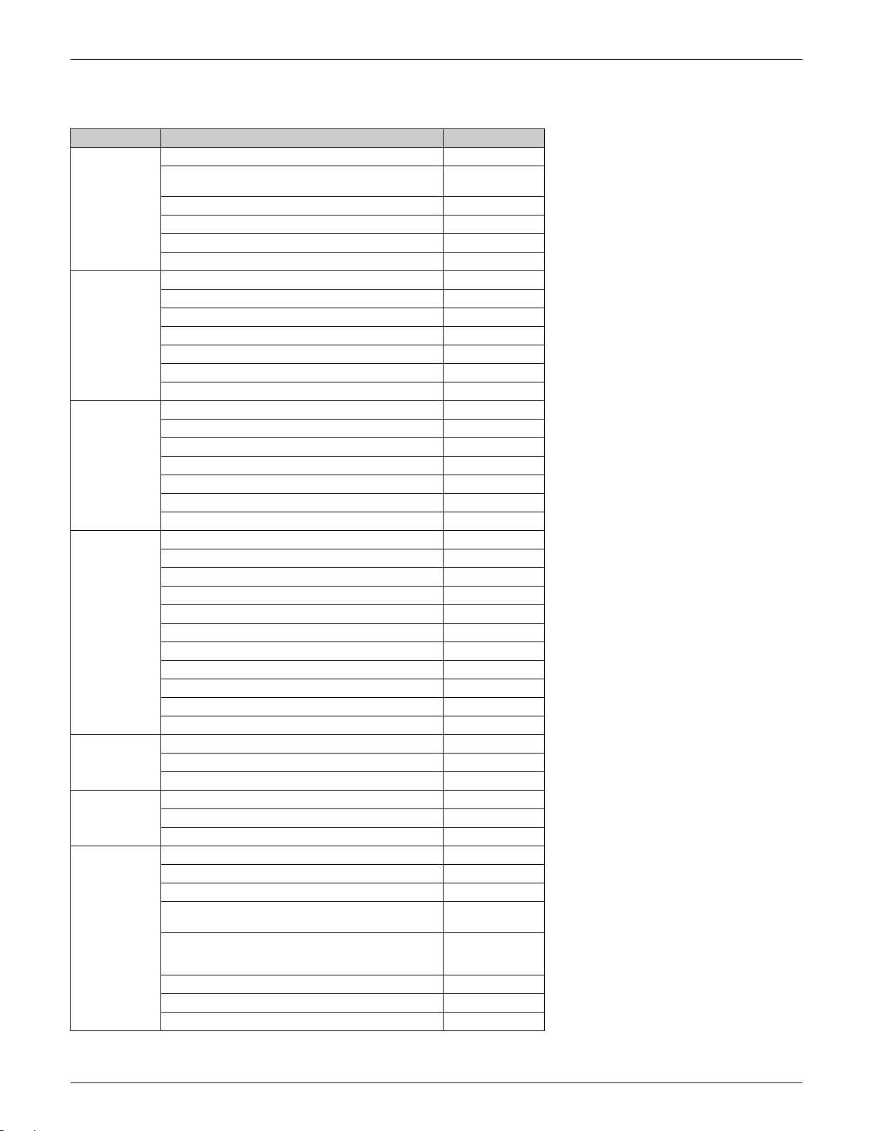
2. Functions
Category Functions FTXR Series
Basic Function Inverter (with inverter power control)
Operation limit Refer to page
PAM control
Swing compressor
Reluctance DC motor
Standby electricity saving —
Comfortable
Airflow
Comfort
Control
Lifestyle
Convenience
Health and
Cleanliness
Timer WEEKLY TIMER operation
Specifications,
Construction
and Service
Power-airflow dual flaps
Wide-angle louvers
Auto-swing (up and down)
Auto-swing (right and left)
3-D airflow
COMFORT AIRFLOW mode
Auto fan speed
Hot-start function
Quick warming function
Automatic defrosting
Automatic cooling/heating changeover
Fan stop when thermo-off in cooling
Program dry function
Fan only operation
Intelligent Eye (auto energy saving)
2-area Intelligent Eye (comfort)
ECONO mode
Inverter POWERFUL operation
Indoor unit quiet operation
OUTDOOR UNIT QUIET operation
Indoor unit ON/OFF switch
Multi-colored indicator lamp
Multi-colored lamp brightness setting
Signal reception indicator
Auto-restart (after power failure)
Titanium apatite deodorizing filter
Mold proof air filter
Wipe-clean flat panel
24-hour ON/OFF TIMER
NIGHT SET mode
Either side drain (right/left)
Self-diagnosis (R/C, LED)
Anti-corrosion treatment of outdoor heat exchanger
Low outdoor temperature cooling operation
(–15°C) (5°F)
Low outdoor temperature cooling operation
(–20°C) (4°F) Requires wind baffle and field
settings
Address setting
Multi-split/split type compatible indoor unit
Chargeless 10 m (32.8 ft)
139
Part 1 General Information 11
Functions SiUS041829E
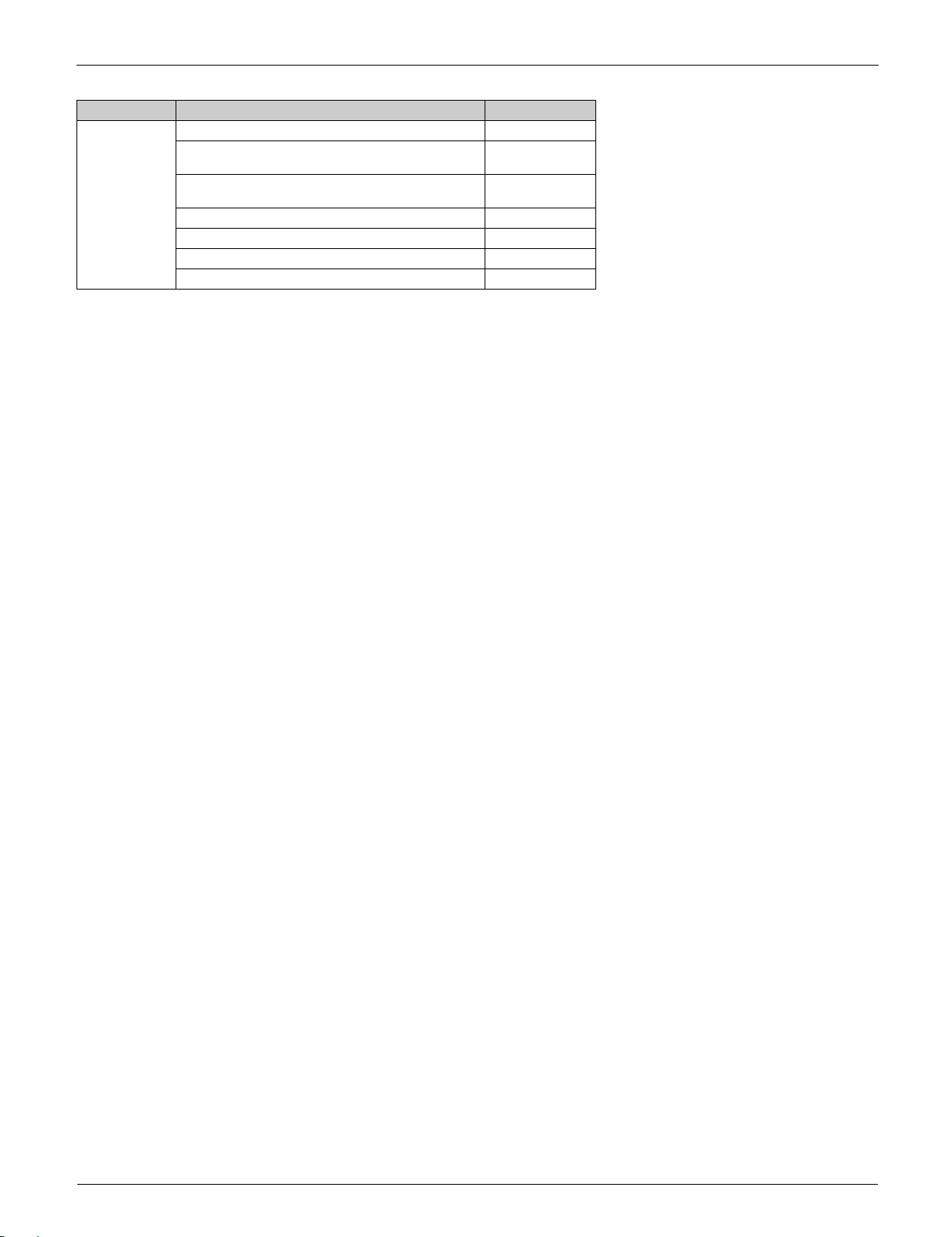
Category Functions FTXR Series
Remote
Control
—: Available
: Not available
R/C with back light
°F/°C changeover R/C temperature display
(factory setting: °F)
Remote control adaptor (normal open pulse
contact)
Remote control adaptor (normal open contact) Option
DIII-NET compatible Option
Wireless LAN connection Option
Wired remote controller Option
Option
12 Part 1 General Information

SiUS041829E
Part 2
Specifications
1. Specifications ............................................................................................14
Part 2 Specifications 13
Specifications SiUS041829E
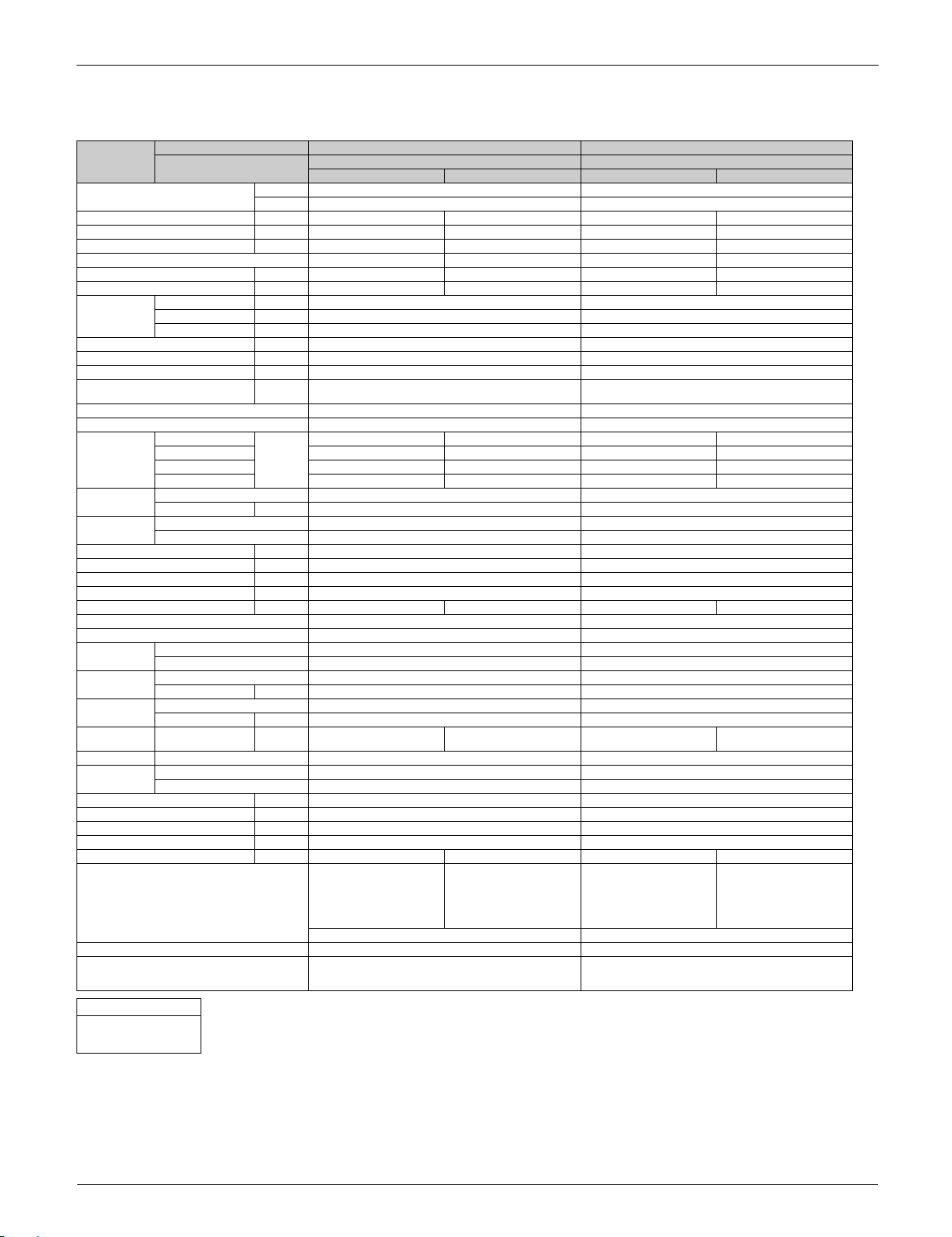
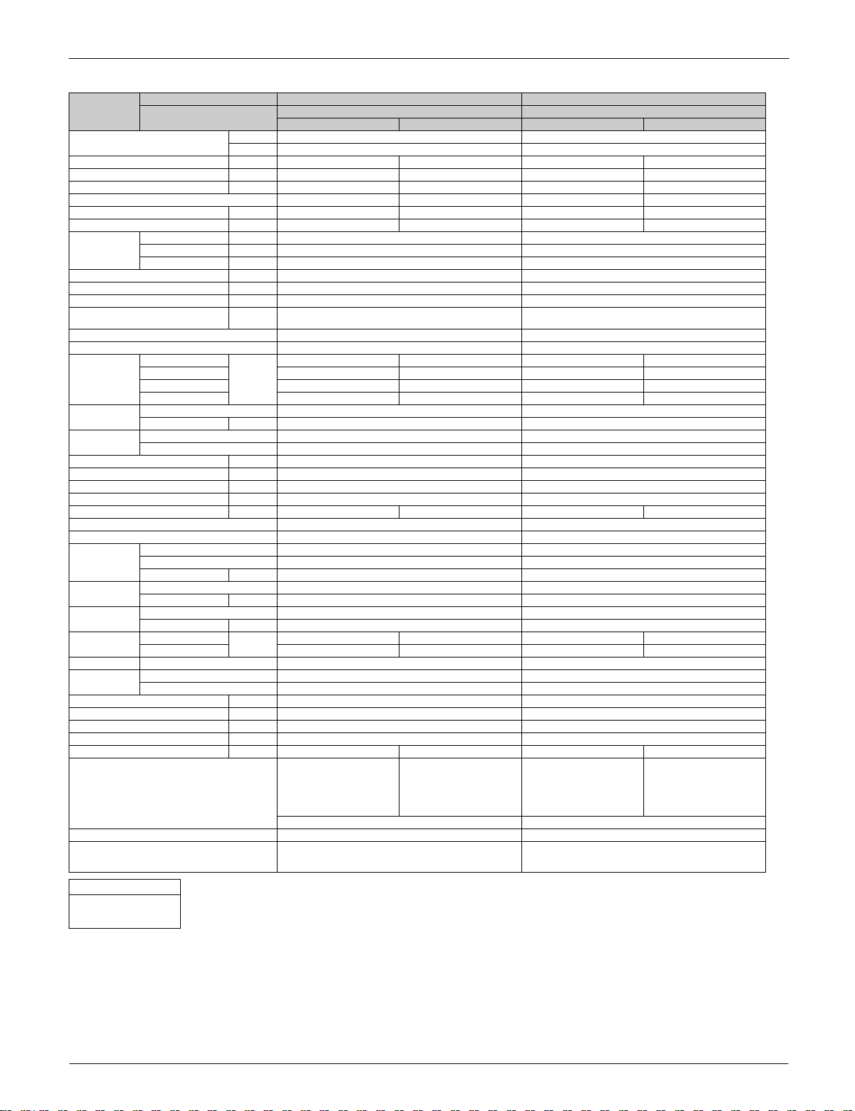
1. Specifications
Model Indoor Unit FTXR09TVJUW FTXR09TVJUS
Power Supply Phase 1 1
Capacity Rated (Min. - Max.) Btu/h 9,000 (4,500 ~ 10,600) 10,000 (4,100 ~ 14,600) 9,000 (4,500 ~ 10,600) 10,000 (4,100 ~ 14,600)
Power Consumption (Rated) W 819 733 819 733
Power Factor (Rated) % 92.0 - 92.0 92.0 - 92.1 92.0 - 92.0 92.0 - 92.1
SEER / HSPF 18.00 9.30 18.00 9.30
EER (Rated) Btu/Wh 11.00 — 11.00 —
COP (Rated) W/W — 4.00 — 4.00
Piping
Connection
Max. Interunit Piping Length ft (m) 65.6 (20) 65.6 (20)
Max. Interunit Height Difference ft (m) 49.2 (15) 49.2 (15)
Chargeless ft (m) 32.8 (10) 32.8 (10)
Amount of Additional Charge of
Refrigerant
Indoor Unit FTXR09TVJUW FTXR09TVJUS
Front Panel Color White Silver
Airflow Rates H
Fan Type Cross Flow Fan Cross Flow Fan
Heat
Exchanger
Dimensions (H × W × D) in. (mm) 11-15/16 × 39-5/16 × 8-3/8 (303 × 998 × 212) 11-15/16 × 39-5/16 × 8-3/8 (303 × 998 × 212)
Packaged Dimensions (H × W × D) in. (mm) 12-11/16 × 43-3/8 × 15-5/16 (322 × 1,101 × 389) 12-11/16 × 43-3/8 × 15-5/16 (322 × 1,101 × 389)
Weight (Mass) Lbs (kg) 27 (12) 27 (12)
Gross Weight (Gross Mass) Lbs (kg) 36 (16) 36 (16)
Sound Pressure Level (H / M / L / SL) dB(A) 38 / 32 / 25 / 19 41 / 34 / 28 / 19 38 / 32 / 25 / 19 41 / 34 / 28 / 19
Outdoor Unit RX09RMVJU9 RX09RMVJU9
Casing Color Ivory White Ivory White
Compressor Type Hermetically Sealed Swing Type Hermetically Sealed Swing Type
Refrigerant Oil Type FVC50K FVC50K
Refrigerant Type R-410A R-410A
Airflow Rates H cfm
Fan Type Propeller Propeller
Heat
Exchanger
Dimensions (H × W × D) in. (mm) 21-5/8 × 26-9/16 × 11-3/16 (550 × 675 × 284) 21-5/8 × 26-9/16 × 11-3/16 (550 × 675 × 284)
Packaged Dimensions (H × W × D) in. (mm) 24-3/4 × 32-11/16 × 16 (629 × 830 × 407) 24-3/4 × 32-11/16 × 16 (629 × 830 × 407)
Weight (Mass) Lbs (kg) 60 (27) 60 (27)
Gross Weight (Gross Mass) Lbs (kg) 71 (32) 71 (32)
Sound Pressure Level (H) dB(A) 46 50 46 50
Conditions Based on Indoor;
Drawing No. 3D120044 3D120044
Notes 1. SL: The quiet fan level of the airflow rate setting.
Conversion Formulae
kcal/h = kW × 860
Btu/h = kW × 3412
cfm = m³/min × 35.3
Outdoor Unit RX09RMVJU9 RX09RMVJU9
Hz, V 60 Hz, 208 - 230 V 60 Hz, 208 - 230 V
Liquid in. (mm) 1/4 (6.4) 1/4 (6.4)
Gas in. (mm) 3/8 (9.5) 3/8 (9.5)
Drain in. (mm) 11/16 (18) 11/16 (18)
oz/ft
(g/m)
M 208 (5.9) 258 (7.3) 208 (5.9) 258 (7.3)
L 162 (4.6) 201 (5.7) 162 (4.6) 201 (5.7)
SL 134 (3.8) 117 (3.3) 134 (3.8) 117 (3.3)
Speed Steps 5 Steps, Quiet, Auto 5 Steps, Quiet, Auto
Type Multi Slit Fin Multi Slit Fin
Rows × Stages, Fin per Inch 2 × 18, 21 2 × 18, 21
Model 1YC23AUXD 1YC23AUXD
Charge oz (L) 12.68 (0.375) 12.68 (0.375)
Charge Lbs (kg) 2.09 (0.95) 2.09 (0.95)
Type Waffle Fin Waffle Fin
Rows × Stages, Fin per Inch 2 × 24, 17 2 × 24, 17
cfm
3
/min)
(m
3
/min)
(m
Cooling Heating Cooling Heating
0.21 (20) 0.21 (20)
272 (7.7) 346 (9.8) 272 (7.7) 346 (9.8)
985 (27.9) 1,130 (32) 985 (27.9) 1,130 (32)
80.0°FDB (26.7°CDB) /
67.0°FWB (19.4°CWB)
Outdoor;
95.0°FDB (35°CDB) /
75°FWB (23.9°CWB)
2. When connected with multi-system outdoor unit, refer to
the specifications of the multi outdoor unit to be connected.
Piping Length: 25 ft Piping Length: 25 ft
Indoor;
80.0°FDB (26.7°CDB) /
67.0°FWB (19.4°CWB)
Outdoor;
95.0°FDB (35°CDB) /
75°FWB (23.9°CWB)
1. SL: The quiet fan level of the airflow rate setting.
2. When connected with multi-system outdoor unit, refer to
the specifications of the multi outdoor unit to be connected.
Indoor;
80.0°FDB (26.7°CDB) /
67.0°FWB (19.4°CWB)
Outdoor;
95.0°FDB (35°CDB) /
75°FWB (23.9°CWB)
Indoor;
80.0°FDB (26.7°CDB) /
67.0°FWB (19.4°CWB)
Outdoor;
95.0°FDB (35°CDB) /
75°FWB (23.9°CWB)
14 Part 2 Specifications

SiUS041829E Specifications
Model Indoor Unit FTXR12TVJUW FTXR12TVJUS
Power Supply Phase 1 1
Capacity Rated (Min. - Max.) Btu/h 12,000 (4,500 ~ 12,800) 13,500 (4,100 ~ 15,800) 12,000 (4,500 ~ 12,800) 13,500 (4,100 ~ 15,800)
Power Consumption Rated W 1,091 1,106 1,091 1,106
Power Factor Rated % 96.1 - 96.0 95.0 - 95.0 96.1 - 96.0 95.0 - 95.0
SEER / HSPF 17.00 10.00 17.00 10.00
EER Rated Btu/Wh 11.00 — 11.00 —
COP Rated W/W — 3.58 — 3.58
Piping
Connection
Max. Interunit Piping Length ft (m) 65.6 (20) 65.6 (20)
Max. Interunit Height Difference ft (m) 49.2 (15) 49.2 (15)
Chargeless ft (m) 32.8 (10) 32.8 (10)
Amount of Additional Charge of
Refrigerant
Indoor Unit FTXR12TVJUW FTXR12TVJUS
Front Panel Color White Silver
Airflow Rates H
Fan Type Cross Flow Fan Cross Flow Fan
Heat
Exchanger
Dimensions (H × W × D) in. (mm) 11-15/16 × 39-5/16 × 8-3/8 (303 × 998 × 212) 11-15/16 × 39-5/16 × 8-3/8 (303 × 998 × 212)
Packaged Dimensions (H × W × D) in. (mm) 12-11/16 × 43-3/8 × 15-5/16 (322 × 1,101 × 389) 12-11/16 × 43-3/8 × 15-5/16 (322 × 1,101 × 389)
Weight (Mass) Lbs (kg) 27 (12) 27 (12)
Gross Weight (Gross Mass) Lbs (kg) 36 (16) 36 (16)
Sound Pressure Level (H / M / L / SL) dB(A) 45 / 34 / 26 / 20 45 / 37 / 29 / 20 45 / 34 / 26 / 20 45 / 37 / 29 / 20
Outdoor Unit RX12RMVJU9 RX12RMVJU9
Casing Color Ivory White Ivory White
Compressor Type Hermetically Sealed Swing Type Hermetically Sealed Swing Type
Refrigerant Oil Type FVC50K FVC50K
Refrigerant Type R-410A R-410A
Airflow Rates H
Fan Type Propeller Propeller
Heat
Exchanger
Dimensions (H × W × D) in. (mm) 21-5/8 × 26-9/16 × 11-3/16 (550 × 675 × 284) 21-5/8 × 26-9/16 × 11-3/16 (550 × 675 × 284)
Packaged Dimensions (H × W × D) in. (mm) 24-3/4 × 32-11/16 × 16 (629 × 830 × 407) 24-3/4 × 32-11/16 × 16 (629 × 830 × 407)
Weight Lbs (kg) 60 (27) 60 (27)
Gross Weight Lbs (kg) 71 (32) 71 (32)
Sound Pressure Level (H) dB(A) 49 51 49 51
Conditions Based on Indoor; 80.0°FDB
Drawing No. 3D120044 3D120044
Notes 1. SL: The quiet fan level of the airflow rate setting.
Conversion Formulae
kcal/h = kW × 860
Btu/h = kW × 3412
cfm = m³/min × 35.3
Outdoor Unit RX12RMVJU9 RX12RMVJU9
Hz, V 60 Hz, 208 - 230 V 60 Hz, 208 - 230 V
Liquid in. (mm) 1/4 (6.4) 1/4 (6.4)
Gas in. (mm) 3/8 (9.5) 3/8 (9.5)
Drain in. (mm) 11/16 (18) 11/16 (18)
oz/ft
(g/m)
M 219 (6.2) 290 (8.2) 219 (6.2) 290 (8.2)
L 169 (4.8) 226 (6.4) 169 (4.8) 226 (6.4)
SL 131 (3.7) 131 (3.7) 131 (3.7) 131 (3.7)
Speed Steps 5 Steps, Quiet, Auto 5 Steps, Quiet, Auto
Type Multi Slit Fin Multi Slit Fin
Rows × Stages, Fin per Inch 2 × 18, 21 2 × 18, 21
Model 1YC23AUXD 1YC23AUXD
Motor Output W — —
Charge oz (L) 12.68 (0.375) 12.68 (0.375)
Charge Lbs (kg) 2.09 (0.95) 2.09 (0.95)
SL ————
Type Waffle Fin Waffle Fin
Rows × Stages, Fin per Inch 2 × 24, 17 2 × 24, 17
cfm
3
/min)
(m
cfm
3
/min)
(m
Cooling Heating Cooling Heating
0.21 (20) 0.21 (20)
335 (9.5) 395 (11.2) 335 (9.5) 395 (11.2)
1,105 (31.3) 1,130 (32) 1,105 (31.3) 1,130 (32)
(26.7°CDB) / 67.0°FWB
(19.4°CWB)
Outdoor; 95.0°FDB
(35°CDB) / 75°FWB
(23.9°CWB)
2. When connected with multi-system outdoor unit, refer to
the specifications of the multi outdoor unit to be connected.
Piping Length: 25 ft Piping Length: 25 ft
Indoor; 70.0°FDB
(21.1°CDB) / 60.0°FWB
(15.6°CWB)
Outdoor; 47°FDB
(8.33°CDB) / 43.0°FWB
(6.11°CWB)
Indoor; 80.0°FDB
(26.7°CDB) / 67.0°FWB
(19.4°CWB)
Outdoor; 95.0°FDB
(35°CDB) / 75°FWB
(23.9°CWB)
1. SL: The quiet fan level of the airflow rate setting.
2. When connected with multi-system outdoor unit, refer to
the specifications of the multi outdoor unit to be connected.
Indoor; 70.0°FDB
(21.1°CDB) / 60.0°FWB
(15.6°CWB)
Outdoor; 47°FDB
(8.33°CDB) / 43.0°FWB
(6.11°CWB)
Part 2 Specifications 15
Specifications SiUS041829E
Model Indoor Unit FTXR18TVJUW FTXR18TVJUS
Power Supply Phase 1 1
Capacity Rated (Min. - Max.) Btu/h 18,000 (5,100 ~ 18,500) 20,000 (5,800 ~ 21,200) 18,000 (5,100 ~ 18,500) 20,000 (5,800 ~ 21,200)
Power Consumption Rated W 1,875 1,755 1,875 1,755
Power Factor Rated % 97.0 - 97.0 97.0 - 97.0 97.0 - 97.0 97.0 - 97.0
SEER / HSPF 14.50 9.80 14.50 9.80
EER Rated Btu/Wh 9.60 — 9.60 —
COP Rated W/W — 3.34 — 3.34
Piping
Connection
Max. Interunit Piping Length ft (m) 98.4 (30) 98.4 (30)
Max. Interunit Height Difference ft (m) 65.6 (20) 65.6 (20)
Chargeless ft (m) 32.8 (10) 32.8 (10)
Amount of Additional Charge of
Refrigerant
Indoor Unit FTXR18TVJUW FTXR18TVJUS
Front Panel Color White Silver
Airflow Rates H
Fan Type Cross Flow Fan Cross Flow Fan
Heat
Exchanger
Dimensions (H × W × D) in. (mm) 11-15/16 × 39-5/16 × 8-3/8 (303 × 998 × 212) 11-15/16 × 39-5/16 × 8-3/8 (303 × 998 × 212)
Packaged Dimensions (H × W × D) in. (mm) 12-11/16 × 43-3/8 × 15-5/16 (322 × 1,101 × 389) 12-11/16 × 43-3/8 × 15-5/16 (322 × 1,101 × 389)
Weight (Mass) Lbs (kg) 27 (12) 27 (12)
Gross Weight (Gross Mass) Lbs (kg) 36 (16) 36 (16)
Sound Pressure Level (H / M / L / SL) dB(A) 46 / 40 / 35 / 30 47 / 41 / 35 / 30 46 / 40 / 35 / 30 47 / 41 / 35 / 30
Outdoor Unit RX18RMVJU9 RX18RMVJU9
Casing Color Ivory White Ivory White
Compressor Type Hermetically Sealed Swing Type Hermetically Sealed Swing Type
Refrigerant Oil Type FVC50K FVC50K
Refrigerant Type R-410A R-410A
Airflow Rates H
Fan Type Propeller Propeller
Heat
Exchanger
Dimensions (H × W × D) in. (mm) 28-15/16 × 34-1/4 × 12-5/8 (735 × 870 × 320) 28-15/16 × 34-1/4 × 12-5/8 (735 × 870 × 320)
Packaged Dimensions (H × W × D) in. (mm) 31-7/8 × 41-9/16 × 17-1/2 (810 × 1,056 × 464) 31-7/8 × 41-9/16 × 17-1/2 (810 × 1,056 × 464)
Weight Lbs (kg) 97 (44) 97 (44)
Gross Weight Lbs (kg) 115 (52) 115 (52)
Sound Pressure Level (H) dB(A) 54 55 54 55
Conditions Based on Indoor; 80.0°FDB
Drawing No. 3D120048A 3D120048A
Notes 1. SL: The quiet fan level of the airflow rate setting.
Conversion Formulae
kcal/h = kW × 860
Btu/h = kW × 3412
cfm = m³/min × 35.3
Outdoor Unit RX18RMVJU9 RX18RMVJU9
Hz, V 60 Hz, 208 - 230 V 60 Hz, 208 - 230 V
Liquid in. (mm) 1/4 (6.4) 1/4 (6.4)
Gas in. (mm) 1/2 (12.7) 1/2 (12.7)
Drain in. (mm) 11/16 (18) 11/16 (18)
oz/ft
(g/m)
M 275 (7.8) 332 (9.4) 275 (7.8) 332 (9.4)
L 226 (6.4) 275 (7.8) 226 (6.4) 275 (7.8)
SL 208 (5.9) 208 (5.9) 208 (5.9) 208 (5.9)
Speed Steps 5 Steps, Quiet, Auto 5 Steps, Quiet, Auto
Type Multi Slit Fin Multi Slit Fin
Rows × Stages, Fin per Inch 2 × 18, 21 2 × 18, 21
Model 2YC36PXD 2YC36PXD
Motor Output W — —
Charge oz (L) 21.98 (0.650) 21.98 (0.650)
Charge Lbs (kg) 2.49 (1.13) 2.49 (1.13)
SL ————
Type Waffle Fin Waffle Fin
Rows × Stages, Fin per Inch 1 × 32, 18 1 × 32, 18
cfm
3
/min)
(m
cfm
3
/min)
(m
Cooling Heating Cooling Heating
0.21 (20) 0.21 (20)
350 (9.9) 413 (11.7) 350 (9.9) 413 (11.7)
2,461 (69.7) 2,553 (72.3) 2,461 (69.7) 2,553 (72.3)
(26.7°CDB) / 67.0°FWB
(19.4°CWB)
Outdoor; 95.0°FDB
(35°CDB) / 75°FWB
(23.9°CWB)
2. When connected with multi-system outdoor unit, refer to
the specifications of the multi outdoor unit to be connected.
Piping Length: 25 ft Piping Length: 25 ft
Indoor; 70.0°FDB
(21.1°CDB) / 60.0°FWB
(15.6°CWB)
Outdoor; 47°FDB
(8.33°CDB) / 43.0°FWB
(6.11°CWB)
Indoor; 80.0°FDB
(26.7°CDB) / 67.0°FWB
(19.4°CWB)
Outdoor; 95.0°FDB
(35°CDB) / 75°FWB
(23.9°CWB)
1. SL: The quiet fan level of the airflow rate setting.
2. When connected with multi-system outdoor unit, refer to
the specifications of the multi outdoor unit to be connected.
Indoor; 70.0°FDB
(21.1°CDB) / 60.0°FWB
(15.6°CWB)
Outdoor; 47°FDB
(8.33°CDB) / 43.0°FWB
(6.11°CWB)
16 Part 2 Specifications

SiUS041829E
Part 3
Printed Circuit Board
Connector Wiring Diagram
1. Indoor Unit.................................................................................................18
1.1 FTXR09/12/18TVJUW(S)........................................................................... 18
2. Outdoor Unit..............................................................................................20
2.1 RX09/12RMVJU9 ....................................................................................... 20
2.2 RX18RMVJU9 ............................................................................................ 21
Part 3 Printed Circuit Board Connector Wiring Diagram 17
Indoor Unit SiUS041829E
Caution
S42
S41
S32
JB
JC
S200
H3H2FG
S46
S21F2U S25
LED A
V1
F1U
H1
2P357399-6
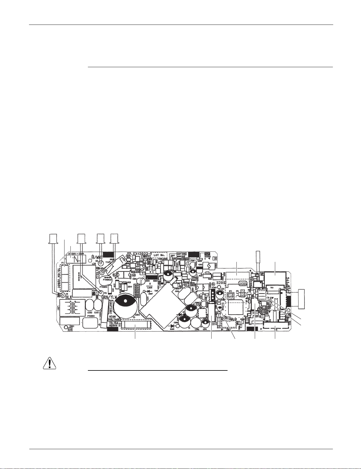
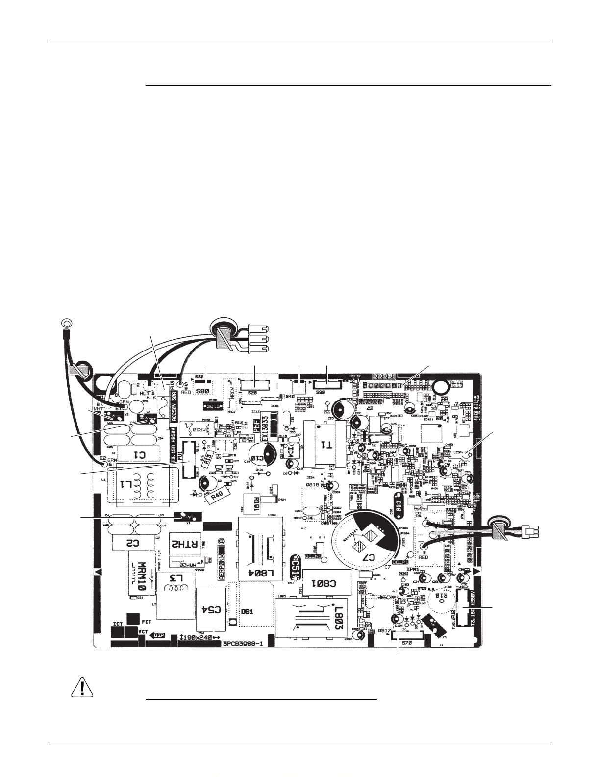
1. Indoor Unit
1.1 FTXR09/12/18TVJUW(S)
Control PCB
(A1P)
1) S21 Connector for centralized control (HA)
2) S25 Connector for INTELLIGENT EYE sensor PCB (A3P)
3) S32 Indoor heat exchanger thermistor
4) S41 Connector for swing motors
5) S42 Connector for reduction motor (front panel mechanism) and limit
switch
6) S46 Connector for display/signal receiver PCB (A2P)
7) S200 Connector for DC fan motor
8) H1, H2, H3 Connector for terminal strip (indoor - outdoor transmission)
9) FG Connector for terminal strip (frame ground)
10) JB Jumper for fan speed setting when compressor stops for
thermostat OFF
Refer to page 130 for details.
11) JC Jumper for power failure recovery function (auto-restart)
Refer to page 130 for details.
12) LED A LED for service monitor (green)
13) F1U, F2U Fuse (3.15 A, 250 V)
14) V1 Varistor
Replace the PCB if you cut a jumper unintentionally.
Jumpers are necessary for electronic circuit. Improper operation may occur if you cut any of them.
18 Part 3 Printed Circuit Board Connector Wiring Diagram
SiUS041829E Indoor Unit
Caution
S52
S51
S1W
JA
H2P
H1P
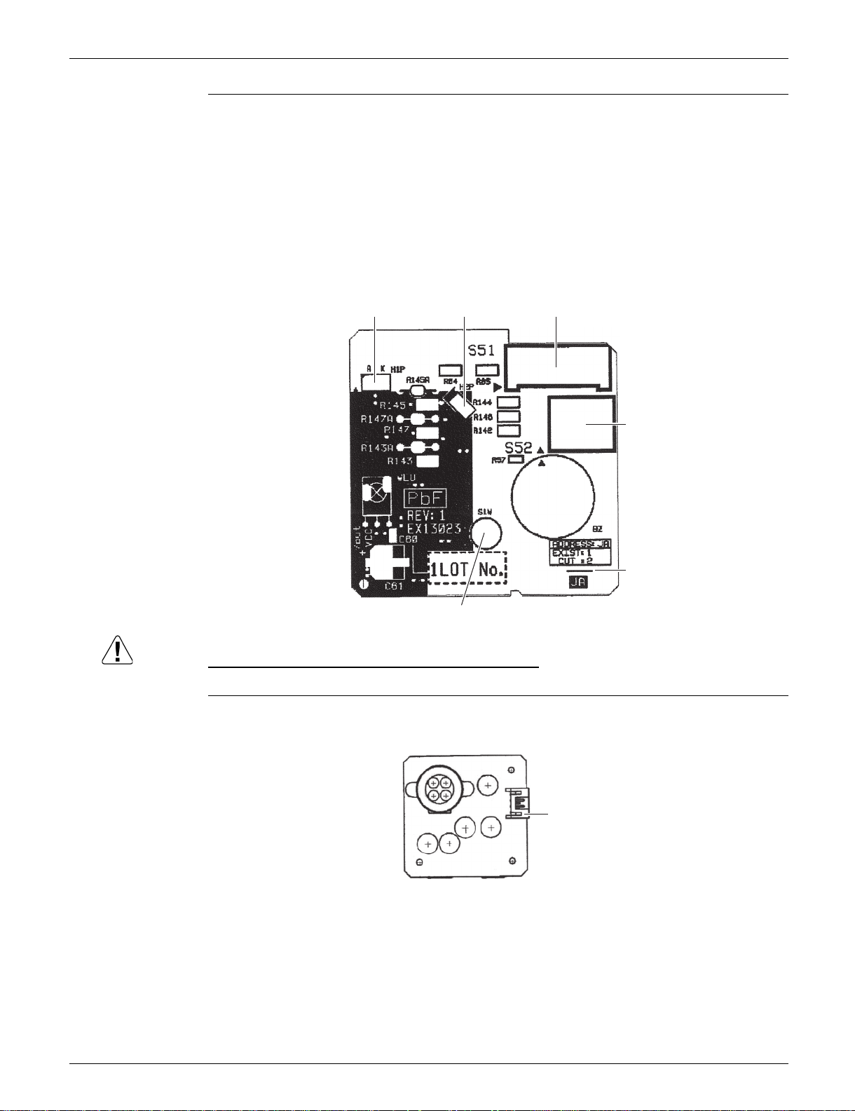
3P357402-2
Display/Signal
Receiver PCB
(A2P)
1) S51 Connector for control PCB (A1P)
2) S52 Connector for room temperature thermistor
3) S1W Indoor unit ON/OFF switch
(Forced cooling operation ON/OFF switch)
Refer to page 126 for details of forced cooling operation.
4) H1P LED for operation (multi-color)
5) H2P LED for INTELLIGENT EYE (green)
6) JA Address setting jumper
Refer to page 129 for details.
Replace the PCB if you cut a jumper unintentionally.
Jumpers are necessary for electronic circuit. Improper operation may occur if you cut any of them.
INTELLIGENT
EYE Sensor PCB
1) S36 Connector for control PCB (A1P)
(A3P)
Part 3 Printed Circuit Board Connector Wiring Diagram 19
S36
3E860004-1
Outdoor Unit SiUS041829E
Caution
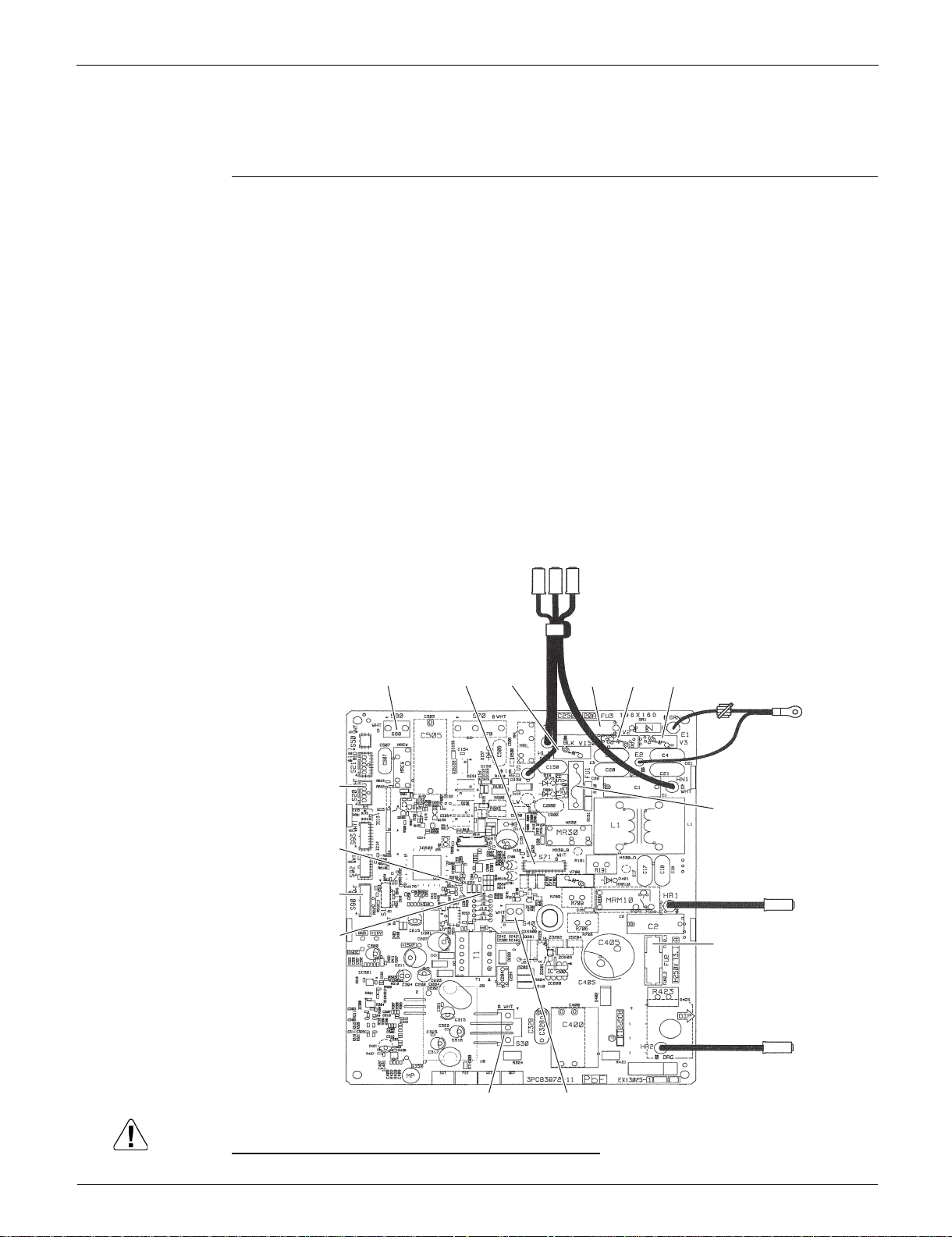
2. Outdoor Unit
2.1 RX09/12RMVJU9
Main PCB (PCB1)
1) S20 Connector for electronic expansion valve coil
2) S30 Connector for compressor
3) S40 Connector for overload protector
4) S71 Connector for DC fan motor
5) S80 Connector for four way valve coil
6) S90 Connector for thermistors
(outdoor temperature, outdoor heat exchanger, discharge pipe)
7) HL1, HN1, S Connector for terminal block
8) E1, E2 Terminal for ground wire
9) HR1, HR2 Connector for reactor
10) FU1, FU2 Fuse (3.15 A, 250 V)
11) FU3 Fuse (20 A, 250 V)
12) J6 Jumper for facility setting
Refer to page 131 for details.
12) LED A LED for service monitor (green)
13) V2, V3, V150 Varistor
S20
LED A
S90
J6
S80 S71
V150
HL1, HN1, S
FU3
V2
V3
E1, E2
FU1
HR1
FU2
HR2
S30
S40
2P504947-90
Replace the PCB if you cut a jumper unintentionally.
Jumpers are necessary for electronic circuit. Improper operation may occur if you cut any of them.
20 Part 3 Printed Circuit Board Connector Wiring Diagram
SiUS041829E Outdoor Unit
Caution
2.2 RX18RMVJU9
Main PCB
1) S20 Connector for electronic expansion valve coil
2) S40 Connector for overload protector
3) S70 Connector for DC fan motor
4) S80 Connector for four way valve coil
5) S90 Connector for thermistors
(outdoor temperature, outdoor heat exchanger, discharge pipe)
6) HL1, HN1, S Connector for terminal block
7) E1, E2 Terminal for ground
8) U, V, W Connector for compressor
9) FU1, FU2 Fuse (3.15 A, 250 V)
10) FU3 Fuse (30 A, 250 V)
11) J6 Jumper for facility setting
Refer to page 131 for details.
12) LED A LED for service monitor (green)
13) V1, V2, V3 Varistor
V2
FU1
V1
E1, E2
V3
HL1, HN1, S
FU3
S80 S20 S40 S90 J6
LED A
U, V, W
FU2
S70
2P443814-55
Replace the PCB if you cut a jumper unintentionally.
Jumpers are necessary for electronic circuit. Improper operation may occur if you cut any of them.
Part 3 Printed Circuit Board Connector Wiring Diagram 21

SiUS041829E
Part 4
Functions and Control
1. Main Functions..........................................................................................23
1.1 Temperature Control .................................................................................. 23
1.2 Frequency Principle.................................................................................... 23
1.3 Airflow Direction Control............................................................................. 25
1.4 Fan Speed Control for Indoor Unit ............................................................. 26
1.5 Program Dry Operation .............................................................................. 27
1.6 Automatic Cooling/Heating Changeover .................................................... 28
1.7 Thermostat Control..................................................................................... 29
1.8 NIGHT SET Mode ...................................................................................... 30
1.9 ECONO Operation .................................................................................... 31
1.10 2-Area INTELLIGENT EYE Operation ....................................................... 32
1.11 POWERFUL Operation .............................................................................. 34
1.12 Multi-Monitor Lamp/TIMER Lamp .............................................................. 35
1.13 Clock Setting .............................................................................................. 36
1.14 WEEKLY TIMER Operation ....................................................................... 37
1.15 Other Functions.......................................................................................... 43
2. Thermistor Functions ................................................................................44
3. Control Specification .................................................................................45
3.1 Mode Hierarchy .......................................................................................... 45
3.2 Frequency Control...................................................................................... 46
3.3 Controls at Mode Changing/Start-up.......................................................... 48
3.4 Discharge Pipe Temperature Control......................................................... 50
3.5 Input Current Control.................................................................................. 51
3.6 Freeze-up Protection Control ..................................................................... 52
3.7 Heating Peak-cut Control ........................................................................... 52
3.8 Outdoor Fan Control................................................................................... 53
3.9 Liquid Compression Protection Function.................................................... 53
3.10 Defrost Control ........................................................................................... 54
3.11 Electronic Expansion Valve Control ........................................................... 55
3.12 Malfunctions ............................................................................................... 58
22 Part 4 Functions and Control
SiUS041829E Main Functions
Target temperature
Set temperature
Room temperature
Room thermistor temperature
(R12321)
1. Main Functions
1.1 Temperature Control
Definitions of
Temperatures
Temperature
Control
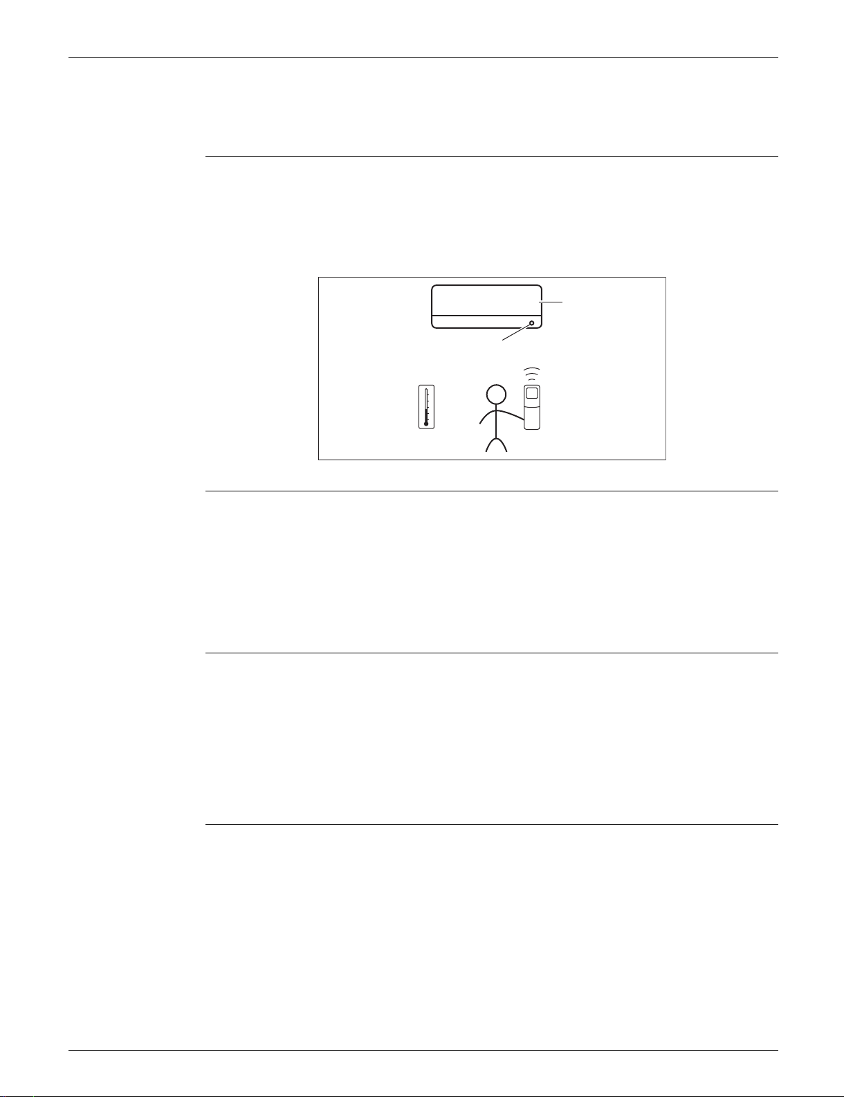
The definitions of temperatures are classified as following.
Room temperature: temperature of lower part of the room
Set temperature: temperature set by remote controller
Room thermistor temperature: temperature detected by room temperature thermistor
Target temperature: temperature determined by microcomputer
The temperature of the room is detected by the room temperature thermistor. However, there is a
difference between the temperature detected by room temperature thermistor and the temperature
of lower part of the room, depending on the type of the indoor unit or installation condition. In
practice, the temperature control is done by the target temperature appropriately adjusted for the
indoor unit and the temperature detected by room temperature thermistor.
1.2 Frequency Principle
Control
Parameters
Inverter Principle To regulate the capacity, a frequency control is needed. The inverter makes it possible to control
The frequency of the compressor is controlled by the following 2 parameters:
The load condition of the operating indoor unit
The difference between the room thermistor temperature and the target temperature
The target frequency is adapted by additional parameters in the following cases:
Frequency restrictions
Initial settings
Forced cooling operation
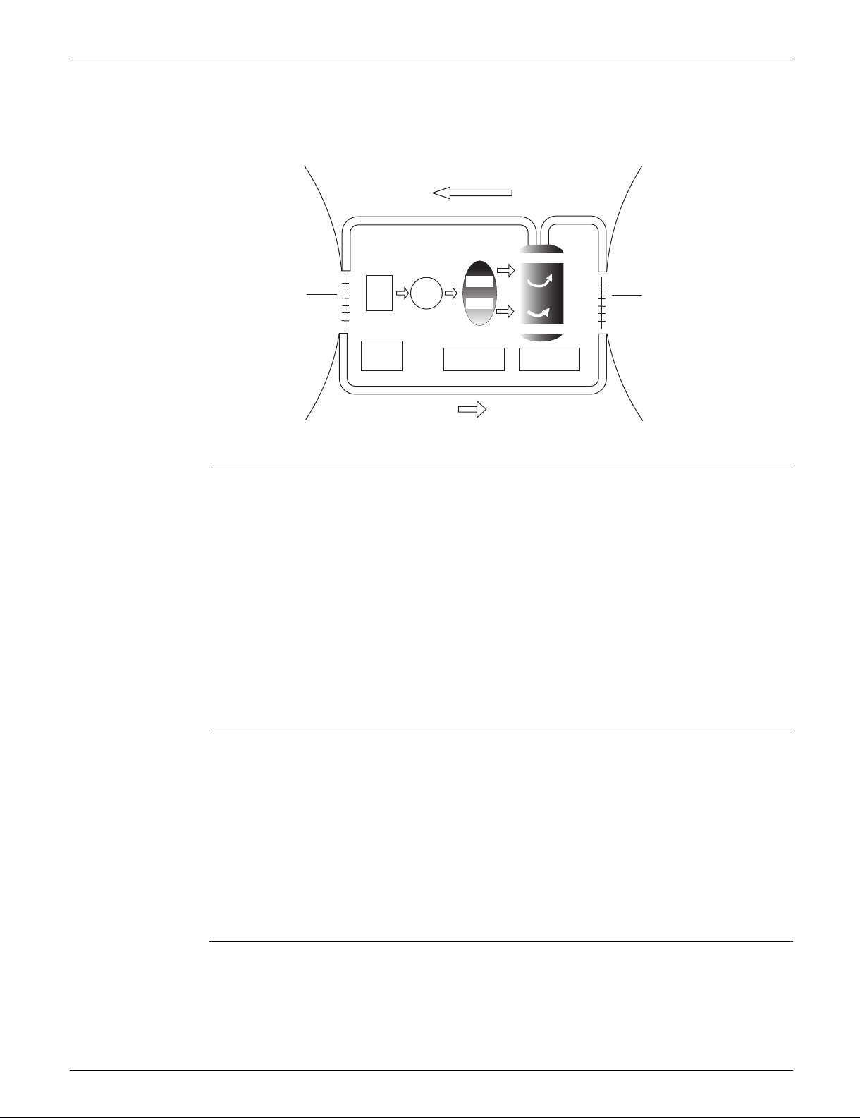
the rotation speed of the compressor. The followings explain the inverter principle:
Phase 1
The supplied AC power source is converted into the DC power source for the present.
Phase 2
The DC power source is reconverted into the three phase AC power source with variable
frequency.
When the frequency increases, the rotation speed of the compressor increases resulting in an
increase of refrigerant circulation. This leads to a larger amount of heat exchange per unit.
Part 4 Functions and Control 23
Main Functions SiUS041829E
Refrigerant circulation rate (high)
high f
low f
freq=variable
Refrigerant circulation rate (low)
high speed
low speed
(R2812)
Amount of heat
exchanged air (large)
freq=
constant
50 Hz 50 Hz
60 Hz60 Hz
capacity=
variable
Amount of heat
exchanged air (small)
AC
power
DC
power
Amount of heat exchanged air
(large)
Amount of heat exchanged air
(small)
When the frequency decreases, the rotation speed of the compressor decreases resulting in a
decrease of refrigerant circulation. This leads to a smaller amount of heat exchange per unit.
The following drawing shows a schematic view of the inverter principle:
Inverter Features The inverter provides the following features:
The regulating capacity can be changed according to the changes in the outdoor temperature
and cooling/heating load.
Quick heating and quick cooling
The rotation speed of the compressor is increased when starting the heating (cooling).
This enables to reach the set temperature quickly.
Even during extreme cold weather, high capacity is achieved. It is maintained even when the
outdoor temperature is 2C (35.6°F).
Comfortable air conditioning
A fine adjustment is integrated to keep the room temperature constant.
Energy saving heating and cooling
Once the set temperature is reached, the energy saving operation enables to maintain the room
temperature at low power.
Frequency Limits The following functions regulate the minimum and maximum frequency:
Low frequency
Four way valve operation compensation. Refer to page 49.
High frequency
Compressor protection function. Refer to page 49.
Discharge pipe temperature control. Refer to page 50.
Input current control. Refer to page 51.
Freeze-up protection control. Refer to page 52.
Heating peak-cut control. Refer to page 52.
Defrost control. Refer to page 54.
Forced Cooling
Operation
24 Part 4 Functions and Control
Refer to page 126 for details.
SiUS041829E Main Functions
(R23915)
50°
30°
(R19554)
(2)
(4)
(3)
(1)
1.3 Airflow Direction Control
Power-Airflow
Dual Flaps
The large flap sends a large volume of air downward to the floor and provides an optimum control in
cooling, dry and heating operation.
Cooling/Dry
During cooling or dry operation, the flap retracts into the indoor unit. Then, cool air can be blown far
and distributed all over the room.
Heating
During heating operation, the large flap directs airflow downward to spread the warm air to the
entire room.
Wide-Angle
Louvers
The louvers, made of elastic synthetic resin, provide a wide range of airflow that guarantees
comfortable air distribution.
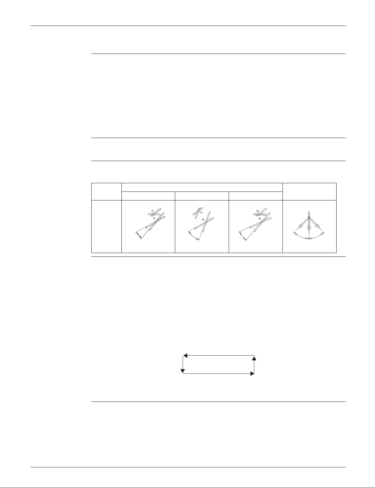
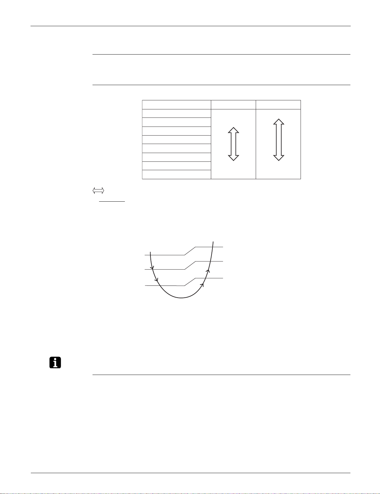
Auto-Swing The following tables explain the auto-swing process for cooling, dry, heating and fan:
09/12/18
class
Flap (up and down)
Cooling/Dry Heating Fan
30°
65°
(R23916)
25°
50°
(R21084)
Louver
(right and left)
35°
35°
(R21085)
3-D Airflow Alternative repetition of vertical and horizontal swing motions enables uniform air-conditioning of
the entire room.
When the horizontal swing and vertical swing are both set to automatic operation, the airflow
becomes 3-D airflow. The horizontal and vertical swing motions are alternated and the airflow
direction changes in the order shown in the following diagram.
(1) The vertical blades (louvers) move from the right to the left.
(2) The horizontal blades (flaps) move downward.
(3) The vertical blades (louvers) move from the left to the right.
(4) The horizontal blades (flaps) move upward.
COMFORT
The flaps are controlled not to blow the air directly at the people in the room.
AIRFLOW
Operation
The airflow direction is upward while in cooling operation, and downward while in heating operation.
This function prevents cold or warm air from blowing directly on the occupants in the room.
Part 4 Functions and Control 25
Main Functions SiUS041829E
Note(s)
1.4 Fan Speed Control for Indoor Unit
Outline Phase control and fan speed control contains 9 steps: LLL, LL, SL, L, ML, M, MH, H, and HH.
The airflow rate can be automatically controlled depending on the difference between the room
thermistor temperature and the target temperature.
Automatic Fan
Speed Control
In automatic fan speed operation, the step SL is not available.
HeatingCoolingStep
LLL
LL
L
ML
M
MH
H
HH (POWERFUL)
= The airflow rate is automatically controlled within this range when FAN setting button is set
to automatic
.
Cooling
The following drawing explains the principle of fan speed control for cooling.
Room thermistor temperature – target temperature
Fan speed
+2.5°C (+4.5°F)
+1.5°C (+2.7°F)
+0.5°C (+0.9°F)
MH*
+3°C (+5.4°F)
M
+2°C (+3.6°F)
ML
+1°C (+1.8°F)
L
R4003512
(R21654)
The upper limit is at M tap in 30 minutes from the operation start.
Heating
In heating operation, the fan speed is regulated according to the indoor heat exchanger
temperature and the difference between the room thermistor temperature and the target
temperature.
The fan stops during defrost operation.
COMFORT
AIRFLOW
Operation
The fan speed is controlled automatically within the following steps.
Cooling
L tap ~ MH tap (same as AUTOMATIC)
Heating
In order to obtain a comfortable airflow, the fan speed may be set to a rate different from
automatic fan speed control.
POWERFUL operation and COMFORT AIRFLOW operation cannot be used at the same time.
26 Part 4 Functions and Control
 Loading...