

Daikin FTXR28EV1B, FTXR42EV1B, FTXR50EV1B Installation manuals
INSTALLATION
MANUAL
R410A Split Series
Models
FTXR28EV1B
FTXR42EV1B
FTXR50EV1B
Installation manual
R410A Split series
Installationsanleitung
Split-Baureihe R410A
Manuel d’installation
Série split R410A
Montagehandleiding
R410A Split-systeem
Manual de instalación
Serie Split R410A
Manuale d’installazione
Serie Multiambienti R410A
Εγχειρßδιο εγκατÜστασηò
διαιροýìενηò σειρÜò R410A
English
Deutsch
Français
Nederlands
Español
Italiano
ΕλληνικÜ
Manual de Instalação
Série split R410A
Рóêоводство по монтажó
Серия R410A с раздельной óстановêой
Montaj kýlavuzlarý
R410A Split serisi
Portugues
Рóссêий
Türkçe
74736-KRQ/EMC97-4957.Daikin.TCF.015
Daikin.TCF.015
Daikin.TCF.015
Daikin.TCF.015
74736-KRQ/EMC97-4957.
74736-KRQ/EMC97-4957.
Daikin.TCF.015
Daikin.TCF.015
Daikin.TCF.015
Daikin.TCF.015
74736-KRQ/EMC97-4957Daikin.TCF.015
Daikin.TCF.015
Daikin.TCF.015,
74736-KRQ/EMC97-4957.
74736-KRQ/EMC97-4957.
74736-KRQ/EMC97-4957.
Daikin.TCF.015
Daikin.TCF.015
Daikin.TCF.015
Daikin.TCF.015
Umeda Center Bldg., 4-12, Nakazaki-Nishi 2-chome,
Kita-ku, Osaka, 530-8323 Japan
74736-KRQ/EMC97-4957.
74736-KRQ/EMC97-4957.
Daikin.TCF.015
Daikin.TCF.015
74736-KRQ/EMC97-4957.
74736-KRQ/EMC97-4957
74736-KRQ/EMC97-4957.
Daikin.TCF.015
Daikin.TCF.015
Daikin.TCF.015
74736-KRQ/EMC97-4957.
74736-KRQ/EMC97-4957.
74736-KRQ/EMC97-4957.
74736-KRQ/EMC97-4957.
74736-KRQ/EMC97-4957.
74736-KRQ/EMC97-4957.
Daikin.TCF.015
Daikin.TCF.015
Daikin.TCF.015
74736-KRQ/EMC97-4957.
74736-KRQ/EMC97-4957.
74736-KRQ/EMC97-4957.
74736-KRQ/EMC97-4957
Daikin.TCF.015
Daikin.TCF.015
74736-KRQ/EMC97-4957.
74736-KRQ/EMC97-4957.
74736-KRQ/EMC97-4957.
Noboru Murata
Manager Quality Control Department
Shiga, 1st of Jun. 2006
DAIKIN INDUSTRIES, LTD.
FTXR28EV1B, FTXR42EV1B, FTXR50EV1B
3SB63767-1
Safety Precautions
• Read these Safety Precautions carefully to ensure correct installation.
• This manual classifies the precautions into WARNING and CAUTION.
Be sure to follow all the precautions below: they are all important for ensuring safety.
WARNIN G
CAUTION...............Failure to follow any of CAUTION may result in grave consequences in some cases.
...............Failure to follow any of WARNING is likely to result in such grave consequences as death or serious injury.
• The following safety symbols are used throughout this manual:
Be sure to observe this instruction. Be sure to establish an earth connection. Never attempt.
• After completing installation, test the unit to check for installation errors. Give the user adequate instructions concerning the use and cleaning of the unit
according to the Operation Manual.
WARNING
• Installation should be left to the dealer or another professional.
Improper installation may cause water leakage, electrical shock, or fire.
• Install the air conditioner according to the instructions given in this manual.
Incomplete installation may cause water leakage, electrical shock, or fire.
• Be sure to use the supplied or specified installation parts.
Use of other parts may cause the unit to come to lose, water leakage, electrical shock, or fire.
• Install the air conditioner on a solid base that can support the weight of the unit.
An inadequate base or incomplete installation may cause injury in the event the unit falls off the base.
• Electrical work should be carried out in accordance with the installation manual and the national electrical wiring
rules or code of practice.
• Be sure to use a dedicated power circuit. Never use a power supply shared by another appliance.
• For wiring, use a cable length enough to cover the entire distance with no connection.
Do not use an extension cord. Do not put other loads on the power supply, use a dedicated power circuit.
(Failure to do so may cause abnormal heat, electric shock or fire.)
• Use the specified types of wires for electrical connections between the indoor and outdoor units.
Firmly clamp the interconnecting wires so their terminals receive no external stresses. Incomplete connections or clamping may cause terminal overheating or fire.
• After connecting interconnecting and supply wiring be sure to shape the cables so that they do not put undue force
on the electrical covers or panels.
Install covers over the wires. Incomplete cover installation may cause terminal overheating, electrical shock, or fire.
• If any refrigerant has leaked out during the installation work, ventilate the room.
(The refrigerant produces a toxic gas if exposed to flames.)
• After all installation is complete, check to make sure that no refrigerant is leaking out.
(The refrigerant produces a toxic gas if exposed to flames.)
• When installing or relocating the system, be sure to keep the refrigerant circuit free from substances other than the
specified refrigerant (R410A), such as air.
(Any presence of air or other foreign substance in the refrigerant circuit causes an abnormal pressure rise or rupture, resulting in injury.)
• During pump-down, stop the compressor before removing the refrigerant piping.
If the compressor is still running and the shut-off valve is open during pump-down, air will be sucked in when the refrigerant piping is removed,
causing abnormal pressure in the freezer cycle which will lead to breakage and even injury.
• During installation, attach the refrigerant piping securely before running the compressor.
If the compressor is not attached and the shut-off valve is open during pump-down, air will be sucked in when the compressor is run, causing
abnormal pressure in the freezer cycle which will lead to breakage and even injury.
• Be sure to establish an earth. Do not earth the unit to a utility pipe, arrester, or telephone earth.
Incomplete earth may cause electrical shock, or fire. A high surge current from lightning or other sources may cause damage to the air conditioner.
• Be sure to install an earth leakage breaker.
Failure to install an earth leakage breaker may result in electric shocks, or fire.
Insufficient capacity or incomplete electrical work may cause electrical shock or fire.
CAUTION
• Do not install the air conditioner in a place where there is danger of exposure to inflammable gas leakage.
If the gas leaks and builds up around the unit, it may catch fire.
• Establish drain piping according to the instructions of this manual.
Inadequate piping may cause flooding.
• Note for installing the outdoor unit. (For heat pump model only.)
In cold area where the outside air temperature keep below or around freezing-point for a few days, the outdoor unit’s drain may freeze.
If so, it is recommended to install an electric heater in order to protect drain from freezing.
• Tighten the flare nut according to the specified method such as with a torque wrench.
If the flare nut is tightened too hard, the flare nut may crack after a long time and cause refrigerant leakage.
1 ■English

Accessories
Mounting plate
A
Deodorizing filter for streamer
B
Titanium apatite photocatalytic
C
air-purifying filter
Air supply filter
D
1
1
1
1
Air supply filter frame
E
Indoor unit fixing screws
F
(M4 × 12L)
Wireless remote controller
G
Remote controller holder
H
1
3
1
1
AAA dry-cell batteries
J
Operation manual
K
Installation manual
L
Choosing an Installation Site
• Before choosing the installation site, obtain user approval.
Indoor unit.
1.
• The indoor unit should be sited in a place where:
1) the restrictions on installation specified in the indoor unit installation drawings are met,
2) both air intake and exhaust have clear paths met,
3) the unit is not in the path of direct sunlight,
4) the unit is away from the source of heat or steam,
5) there is no source of machine oil vapour (this may shorten indoor unit life),
6) cool (warm) air is circulated throughout the room,
7) the unit is away from electronic ignition type fluorescent lamps (inverter or rapid start type) as they may shorten the
remote control range,
8) the unit is at least 1 metre away from any television or radio set (unit may cause interference with the picture or sound),
9) install at the recommended height (1.8m).
2
1
1
Wireless remote controller.
2.
1) Turn on all the fluorescent lamps in the room, if any, and find the site where remote control signals are properly received
by the indoor unit (within 7 metres).
Indoor Unit Installation Drawings
Precautions for humidifying hose installation work.
1.
• When embedding humidifying hose:
1) Cannot be installed to the existing embedded piping. Embedding work is separately necessary.
• The length of the humidifying hose is marked on the hose packing material.
1) Use an extension hose (sold separately) when extending the humidifying hose.
2) The length of the humidifying hose needs to be set to ensure humidifying capacity. Cut off any excess hose.
Use the remote controller to set the hose length. (Refer to page 12.)
• If the humidifying hose needs to be cut to be laid, cut it, lay it, and connect it using the joint or elbow included with the
outdoor unit. When doing this, wrap it to prevent air leaks with the binding band included with the outdoor unit.
(Refer to page 9.)
• When laying the humidifying hose inside the wall, block the ends of the humidifying hose with tape or the like to prevent
water or anything else from entering it until it is connected to the indoor unit and outdoor unit ducts.
• Do not bend the humidifying hose more than 90°.
■English 2
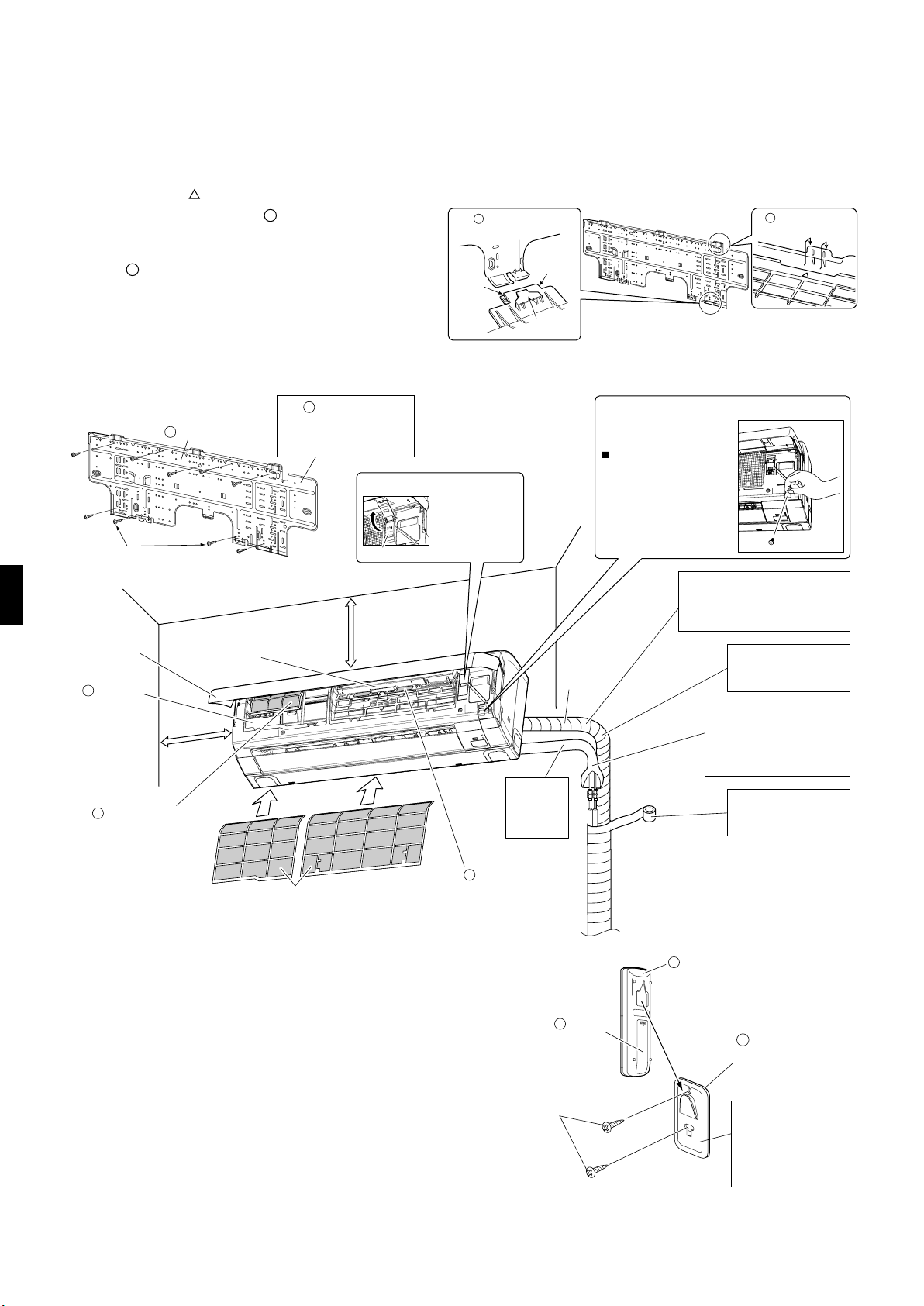
Indoor Unit Installation Drawings
Removing and installing indoor unit.
2.
• Installation method
1) Using the marks (3 locations) on top of the
indoor unit, attach the mounting plate hooks
onto the indoor unit.
2) Attach the tabs on the bottom frame onto the
A
mounting plate. If the tabs are not hooked onto
the plate, remove the front grille to hook them.
(Check to see if the tabs are hooked securely.)
• Removal method
Push up the mark part on the bottom of the front
grille, discharge the tabs, and then remove the unit
while lifting it up.
A
A
Mounting
plate
Mark
(rear side)
Bottom
frame
Ta b
To remove the unit, push up the bottom of the bottom
frame with your fingers to free tabs.
(Mark parts (2 locations) on the bottom of the front grille.)
A
Mounting
plate
Screws
(Field supply: M4 × 25L)
Front panel
Air supply
D
filter
50mm or more
from walls
(on both sides)
C
Titanium apatite
photocatalytic
air-purifying filter
A
Mounting plate
The securing tape is applied.
Be sure to remove it before
installation.
A
The mounting plate
should be installed on a
wall which can support the
weight of the indoor unit.
Supporting plate
Supporting plate
30mm or more
from ceiling
Use when
opening the
front panel and
securing.
Install the
hose with a
downward
slope.
How to open the service lid
The service lid is
removable.
n
Opening the lid
1) Remove the screws
on the service lid.
2) Hold the knobs on the
service lid and pull
forward.
Humidifying
hose
2)
1)
If it is difficult to lay the humidifying
hose, cut it, lay it, and connect it
using the joint or elbow included
with the outdoor unit.
Do not install the trap to
the humidifying hose as
much as possible.
Cut thermal insulation pipe
to an appropriate length and
wrap it with tape, making
sure that no gap is left in the
insulation pipe’s cut line.
Wrap the insulation
pipe with the finishing
tape from bottom to top.
B
Deodorizing filter
Air filter
for streamer
Set the
batteries.
J
Screws
(Field supply: M3 × 20L)
Wireless
G
remote controller
Hook
H
Remote
controller holder
Before screwing the
remote controller
holder to the wall,
make sure that control
signals are properly
received by indoor unit.
3 ■English
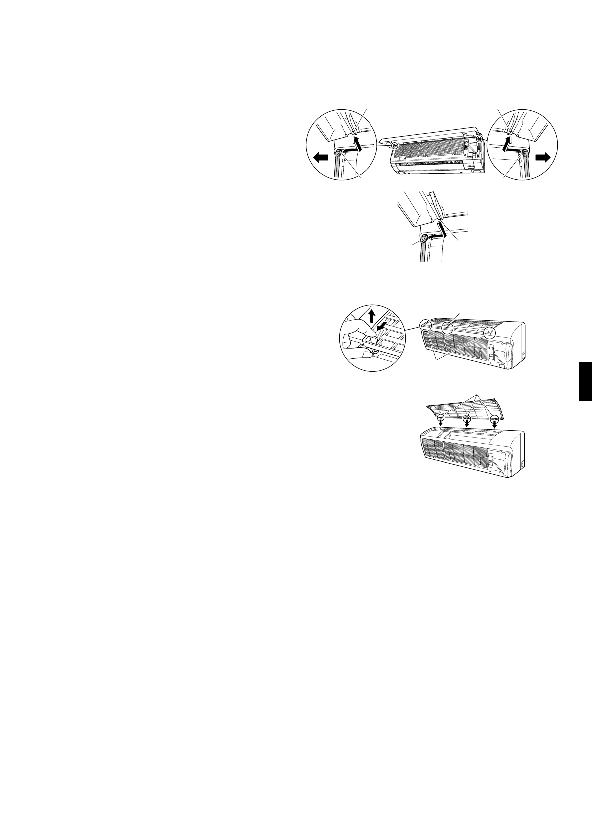
Installation Tips
Removing and installing front panel.
1.
• Removal method
1) Open the front panel.
2) Spread out the shaft hole on the left side and
remove the rotating shaft.
Spread out the shaft hole on the right side as well
and remove the rotating shaft.
• Installation method
Insert the right and left rotating shafts on the front
panel into the shaft holes one at a time and slowly
close the panel.
(Press on both sides of the front panel.)
Removing and installing the upper panel.
2.
• Removal method
1) Remove the front panel and air filter.
2) Hold and pull forward 2 tabs on both sides to
discharge them, discharge the center tab, and then
lift up the upper panel.
• Installation method
1) Push in the upper panel along the guide on the top
of the front grille and insert the 3 tabs into the slots
on the front grille.
2) Push the upper panel down until it clicks.
3) Attach the air filter and front panel.
Rotating shaft
Shaft hole
Rotating shaft
Shaft hole
Rotating shaftShaft hole
Tab (Center)
Tabs
(2 on both sides)
Tabs (3 locations)
■English 4
 Loading...