

Daikin FTXR12TVJUW, FTXR09TVJUS, FTXR12TVJUS, FTXR09TVJUW, FTXR18TVJUW Service Manual
...
Service
Manual
SiUS121827E
Multi-Split Type Air Conditioners
5MXS-T, 4MXL-T Series
[Applied Models]
Inverter Pair : Heat Pump

SiUS121827E
Introduction .......................................................................................1
1. Safety Cautions...........................................................................................2
1.1 Warnings and Cautions Regarding Safety of Workers................................. 2
1.2 Warnings and Cautions Regarding Safety of Users..................................... 4
2. Icons Used ..................................................................................................7
3. Revision History ..........................................................................................8
Part 1 General Information ...............................................................9
1. Applicable Models .....................................................................................10
1.1 Heat Pump ................................................................................................. 10
2. Functions...................................................................................................11
2.1 RA Indoor Unit............................................................................................ 11
2.2 SA Indoor Unit ............................................................................................ 17
2.3 Outdoor Unit ............................................................................................... 21
Part 2 Specifications....................................................................... 22
1. Specifications ............................................................................................23
1.1 RA Indoor Unit............................................................................................ 23
1.2 SA Indoor Unit ............................................................................................ 31
1.3 Outdoor Unit ............................................................................................... 34
Part 3 Printed Circuit Board Connector Wiring Diagram................ 36
1. Indoor Unit.................................................................................................37
1.1 FTXR09/12/18TVJUW(S), CTXG09/12/18QVJUW(S) ............................... 37
1.2 CTXS07LVJU, FTXS09/12LVJU ................................................................ 39
1.3 FTXS15/18/24LVJU ................................................................................... 41
1.4 FDXS09/12LVJU, CDXS15/18/24LVJU ..................................................... 43
1.5 FVXS09/12/15/18NVJU.............................................................................. 45
1.6 FDMQ09/12/15/18/24RVJU ....................................................................... 47
1.7 FFQ09/12/15/18Q2VJU.............................................................................. 49
2. Sensor Kit for FFQ Series .........................................................................50
2.1 BRYQ60A2W(S)......................................................................................... 50
3. Wired Remote Controller...........................................................................51
3.1 BRC1E73 ................................................................................................... 51
4. Wireless Remote Controller Receiver for FDMQ series............................ 52
4.1 BRC082A43 ............................................................................................... 52
5. Wireless Remote Controller Kit for FFQ Series ........................................53
5.1 BRC082A41W, BRC082A42W(S).............................................................. 53
6. Outdoor Unit..............................................................................................54
Part 4 Functions and Control .......................................................... 57
1. Common Functions ...................................................................................59
1.1 Temperature Control .................................................................................. 59
1.2 Frequency Principle.................................................................................... 59
i Table of Contents

SiUS121827E
2. RA Indoor Unit Functions ..........................................................................61
2.1 Airflow Direction Control............................................................................. 61
2.2 Fan Speed Control for Indoor Unit ............................................................. 64
2.3 Program Dry Operation .............................................................................. 65
2.4 Automatic Cooling/Heating Changeover .................................................... 66
2.5 Thermostat Control..................................................................................... 67
2.6 NIGHT SET Mode ...................................................................................... 68
2.7 ECONO Operation .................................................................................... 69
2.8 2-Area INTELLIGENT EYE Operation ....................................................... 70
2.9 INTELLIGENT EYE Operation ................................................................... 72
2.10 POWERFUL Operation .............................................................................. 73
2.11 Multi-Monitor Lamp/TIMER Lamp .............................................................. 74
2.12 Clock Setting .............................................................................................. 75
2.13 WEEKLY TIMER Operation ....................................................................... 76
2.14 Other Functions.......................................................................................... 82
3. SA Indoor Unit Functions ..........................................................................84
3.1 Airflow Direction Control............................................................................. 84
3.2 Fan Speed Control for Indoor Unit ............................................................. 85
3.3 Program Dry Operation .............................................................................. 86
3.4 Clock and Calendar Setting (With Wired Remote Controller BRC1E73) ... 87
3.5 Schedule TIMER Operation (With Wired Remote Controller BRC1E73) ... 89
3.6 Setback Function (With Wired Remote Controller BRC1E73) ................... 93
3.7 Drain Pump Control.................................................................................... 94
3.8 Hot Start Control (In Heating Operation Only)............................................ 96
3.9 Presence and Floor Sensors (Option)........................................................ 97
3.10 Other Functions........................................................................................ 100
4. Control Specification ...............................................................................102
4.1 Thermistor Functions................................................................................ 102
4.2 Mode Hierarchy ........................................................................................ 104
4.3 Frequency Control.................................................................................... 105
4.4 Controls at Mode Changing/Start-up........................................................ 107
4.5 Discharge Pipe Temperature Control....................................................... 109
4.6 Input Current Control................................................................................ 110
4.7 Freeze-up Protection Control ................................................................... 111
4.8 Heating Peak-cut Control ......................................................................... 113
4.9 Outdoor Fan Control................................................................................. 114
4.10 Liquid Compression Protection Function.................................................. 114
4.11 Defrost Control ......................................................................................... 114
4.12 Low Hz High Pressure Limit ..................................................................... 116
4.13 Electronic Expansion Valve Control ......................................................... 116
4.14 Malfunctions ............................................................................................. 121
Table of Contents ii

SiUS121827E
Part 5 Remote Controller ..............................................................122
1. Applicable Remote Controller .................................................................123
2. ARC466A36 ............................................................................................124
3. ARC452A21 ............................................................................................126
4. ARC452A23 ............................................................................................128
5. ARC466A21 ............................................................................................130
6. BRC944B2 Wired Remote Controller......................................................132
7. BRC1E73 Wired Remote Controller........................................................133
8. BRC082A43 Wireless Remote Controller ...............................................139
9. BRC082A41W, BRC082A42W(S) Wireless Remote Controller.............. 141
Part 6 Service Diagnosis ...............................................................143
1. General Problem Symptoms and Check Items .......................................145
2. Troubleshooting with LED .......................................................................146
2.1 Indoor Unit................................................................................................ 146
2.2 Outdoor Unit ............................................................................................. 149
3. Service Diagnosis ................................................................................... 150
3.1 ARC452 Series Wireless Remote Controller............................................ 150
3.2 ARC466 Series Wireless Remote Controller............................................ 153
3.3 BRC1E73 Wired Remote Controller......................................................... 156
3.4 BRC082A43, BRC082A41W, BRC082A42W(S) Wireless Remote Controller
................................................................................................................. 158
4. Code Indication on Remote Controller ....................................................162
4.1 RA Indoor Unit.......................................................................................... 162
4.2 SA Indoor Unit .......................................................................................... 162
4.3 Outdoor Unit ............................................................................................. 163
5. Troubleshooting for RA Indoor Unit.........................................................164
5.1 Indoor Unit PCB Abnormality ................................................................... 164
5.2 Freeze-up Protection Control/Heating Peak-cut Control .......................... 166
5.3 Indoor Fan Motor or Related Abnormality ................................................ 167
5.4 Thermistor or Related Abnormality........................................................... 172
5.5 Front Panel Open/Close Fault.................................................................. 173
5.6 Signal Transmission Error (Between Indoor Unit and Outdoor Unit)........ 174
5.7 Mismatching of Indoor Unit and Outdoor Unit .......................................... 177
6. Troubleshooting for SA Indoor Unit.........................................................178
6.1 Indoor Unit PCB Abnormality ................................................................... 178
6.2 Drain Level Control System Abnormality.................................................. 179
6.3 Indoor Fan Motor or Related Abnormality ................................................ 180
6.4 Indoor Fan PCB Abnormality.................................................................... 185
6.5 Humidifier or Related Abnormality............................................................ 186
6.6 Thermistor or Related Abnormality........................................................... 187
6.7 Presence Sensor or Floor Sensor Abnormality ........................................ 188
6.8 Remote Controller Thermistor Abnormality .............................................. 189
6.9 Signal Transmission Error (Between Indoor and Outdoor Unit) ............... 190
6.10 Signal Transmission Error (Between Indoor Unit and Remote Controller)
................................................................................................................. 192
iii Table of Contents

SiUS121827E
6.11 Signal Transmission Error (Between MAIN/SUB Remote Controllers) .... 193
6.12 Mismatching of Indoor Unit and Outdoor Unit .......................................... 194
7. Troubleshooting for Outdoor Unit............................................................195
7.1 Refrigerant Shortage ................................................................................ 195
7.2 Low-voltage Detection or Over-voltage Detection.................................... 198
7.3 Wiring Error Check Unexecuted............................................................... 200
7.4 Unspecified Voltage (Between Indoor Unit and Outdoor Unit), Anti-icing
Control in Other Rooms............................................................................ 201
7.5 Anti-icing Control for Indoor Unit .............................................................. 202
7.6 Outdoor Unit PCB Abnormality................................................................. 204
7.7 OL Activation (Compressor Overload) ..................................................... 205
7.8 Compressor Lock ..................................................................................... 208
7.9 DC Fan Lock ............................................................................................ 210
7.10 Input Overcurrent Detection ..................................................................... 212
7.11 Four Way Valve Abnormality.................................................................... 214
7.12 Discharge Pipe Temperature Control....................................................... 216
7.13 High Pressure Control in Cooling ............................................................. 217
7.14 Compressor Sensor System Abnormality ................................................ 219
7.15 Position Sensor Abnormality .................................................................... 221
7.16 Thermistor or Related Abnormality (Outdoor Unit)................................... 224
7.17 Electrical Box Temperature Rise.............................................................. 226
7.18 Radiation Fin Temperature Rise .............................................................. 227
7.19 Output Overcurrent Detection .................................................................. 229
8. Check ......................................................................................................232
8.1 Thermistor Resistance Check .................................................................. 232
8.2 Indoor Fan Motor Connector Check......................................................... 233
8.3 Hall IC Check ........................................................................................... 234
8.4 Power Supply Waveform Check............................................................... 235
8.5 Electronic Expansion Valve Check........................................................... 236
8.6 Four Way Valve Performance Check ....................................................... 237
8.7 Inverter Unit Refrigerant System Check................................................... 237
8.8 Inverter Analyzer Check........................................................................... 238
8.9 Rotation Pulse Check on the Outdoor Unit PCB ...................................... 240
8.10 Installation Condition Check..................................................................... 240
8.11 Discharge Pressure Check....................................................................... 241
8.12 Outdoor Fan System Check ..................................................................... 241
8.13 Main Circuit Short Check.......................................................................... 242
8.14 Capacitor Voltage Check.......................................................................... 244
8.15 Power Module Check ............................................................................... 245
Part 7 Trial Operation and Field Settings ..................................... 246
1. Pump Down Operation............................................................................247
2. Forced Cooling Operation .......................................................................248
3. Wiring Error Check Function ...................................................................249
4. Trial Operation ........................................................................................251
4.1 RA Indoor Unit.......................................................................................... 251
4.2 SA Indoor Unit .......................................................................................... 253
Table of Contents iv

SiUS121827E
5. Field Settings .......................................................................................... 256
5.1 RA Indoor Unit.......................................................................................... 256
5.2 SA Indoor Unit .......................................................................................... 262
5.3 Outdoor Unit ............................................................................................. 274
6. Silicone Grease on Power Transistor/Diode Bridge................................ 277
Part 8 Appendix .............................................................................278
1. Piping Diagrams......................................................................................279
1.1 Indoor Unit................................................................................................ 279
1.2 Outdoor Unit ............................................................................................. 282
2. Wiring Diagrams......................................................................................283
2.1 Indoor Unit................................................................................................ 283
3. Outdoor Unit............................................................................................290
4. Operation Limit........................................................................................292
v Table of Contents

SiUS121827E
Introduction
1. Safety Cautions...........................................................................................2
1.1 Warnings and Cautions Regarding Safety of Workers................................. 2
1.2 Warnings and Cautions Regarding Safety of Users..................................... 4
2. Icons Used ..................................................................................................7
3. Revision History ..........................................................................................8
Introduction 1
Safety Cautions SiUS121827E
Warning
1. Safety Cautions
Be sure to read the following safety cautions before conducting repair work.
After the repair work is complete, be sure to conduct a test operation to ensure that the equipment
operates normally, and explain the cautions for operating the product to the customer.
This manual is for the
person in charge of
maintenance and
inspection.
Caution Items The caution items are classified into Warning and Caution. The Warning items are
especially important since death or serious injury can result if they are not followed closely. The
Caution items can also lead to serious accidents under some conditions if they are not
followed. Therefore, be sure to observe all the safety caution items described below.
Pictograms This symbol indicates an item for which caution must be exercised.
The pictogram shows the item to which attention must be paid.
This symbol indicates a prohibited action.
The prohibited item or action is shown in the illustration or near the symbol.
This symbol indicates an action that must be taken, or an instruction.
The instruction is shown in the illustration or near the symbol.
1.1 Warnings and Cautions Regarding Safety of Workers
Do not store equipment in a room with fire sources (e.g., naked
flames, gas appliances, electric heaters).
Be sure to disconnect the power cable from the socket before
disassembling equipment for repair.
Working on equipment that is connected to the power supply may cause
an electrical shock.
If it is necessary to supply power to the equipment to conduct the repair or
inspect the circuits, do not touch any electrically charged sections of the
equipment.
If refrigerant gas is discharged during repair work, do not touch the
discharged refrigerant gas.
Refrigerant gas may cause frostbite.
When disconnecting the suction or discharge pipe of the
compressor at the welded section, evacuate the refrigerant gas
completely at a well-ventilated place first.
If there is gas remaining inside the compressor, the refrigerant gas or
refrigerating machine oil discharges when the pipe is disconnected, and it
may cause injury.
If refrigerant gas leaks during repair work, ventilate the area.
Refrigerant gas may generate toxic gases when it contacts flames.
2 Introduction
SiUS121827E Safety Cautions
Caution
Warning
Be sure to discharge the capacitor completely before conducting
repair work.
The step-up capacitor supplies high-voltage electricity to the electrical
components of the outdoor unit.
A charged capacitor may cause an electrical shock.
Do not turn the air conditioner on or off by plugging in or
unplugging the power cable.
Plugging in or unplugging the power cable to operate the equipment may
cause an electrical shock or fire.
Be sure to wear a safety helmet, gloves, and a safety belt when
working in a high place (more than 2 m (6.5 ft)).
Insufficient safety measures may cause a fall.
In case of R-32 / R-410A refrigerant models, be sure to use pipes,
flare nuts and tools intended for the exclusive use with the R-32 / R410A refrigerant.
The use of materials for R-22 refrigerant models may cause a serious
accident, such as a damage of refrigerant cycle or equipment failure.
Do not mix air or gas other than the specified refrigerant (R-32 / R410A / R-22) in the refrigerant system.
If air enters the refrigerant system, an excessively high pressure results,
causing equipment damage and injury.
Do not repair electrical components with wet hands.
Working on the equipment with wet hands may cause an electrical shock.
Do not clean the air conditioner with water.
Washing the unit with water may cause an electrical shock.
Be sure to provide an earth / grounding when repairing the
equipment in a humid or wet place, to avoid electrical shocks.
Be sure to turn off the power switch and unplug the power cable
when cleaning the equipment.
The internal fan rotates at a high speed, and may cause injury.
Be sure to conduct repair work with appropriate tools.
The use of inappropriate tools may cause injury.
Introduction 3
Safety Cautions SiUS121827E
Caution
Warning
Be sure to check that the refrigerating cycle section has cooled
down enough before conducting repair work.
Working on the unit when the refrigerating cycle section is hot may cause
burns.
Conduct welding work in a well-ventilated place.
Using the welder in an enclosed room may cause oxygen deficiency.
1.2 Warnings and Cautions Regarding Safety of Users
Do not store the equipment in a room with fire sources (e.g., naked
flames, gas appliances, electric heaters).
Be sure to use parts listed in the service parts list of the applicable
model and appropriate tools to conduct repair work. Never attempt
to modify the equipment.
The use of inappropriate parts or tools may cause an electrical shock,
excessive heat generation or fire.
If the power cable and lead wires are scratched or have deteriorated,
be sure to replace them.
Damaged cable and wires may cause an electrical shock, excessive heat
generation or fire.
Do not use a joined power cable or extension cable, or share the
same power outlet with other electrical appliances, since it may
cause an electrical shock, excessive heat generation or fire.
Be sure to use an exclusive power circuit for the equipment, and
follow the local technical standards related to the electrical
equipment, the internal wiring regulations, and the instruction
manual for installation when conducting electrical work.
Insufficient power circuit capacity and improper electrical work may cause
an electrical shock or fire.
Be sure to use the specified cable for wiring between the indoor and
outdoor units.
Make the connections securely and route the cable properly so that there
is no force pulling the cable at the connection terminals.
Improper connections may cause excessive heat generation or fire.
When wiring between the indoor and outdoor units, make sure that
the terminal cover does not lift off or dismount because of the cable.
If the cover is not mounted properly, the terminal connection section may
cause an electrical shock, excessive heat generation or fire.
Do not damage or modify the power cable.
Damaged or modified power cables may cause an electrical shock or fire.
Placing heavy items on the power cable, or heating or pulling the power
cable may damage it.
4 Introduction

SiUS121827E Safety Cautions
Caution
Warning
Do not mix air or gas other than the specified refrigerant (R-32 / R410A / R-22) in the refrigerant system.
If air enters the refrigerant system, an excessively high pressure results,
causing equipment damage and injury.
If the refrigerant gas leaks, be sure to locate the leaking point and
repair it before charging the refrigerant. After charging the
refrigerant, make sure that there is no leak.
If the leaking point cannot be located and the repair work must be
stopped, be sure to pump-down, and close the service valve, to prevent
refrigerant gas from leaking into the room. Refrigerant gas itself is
harmless, but it may generate toxic gases when it contacts flames, such
as those from fan type and other heaters, stoves and ranges.
When relocating the equipment, make sure that the new installation
site has sufficient strength to withstand the weight of the
equipment.
If the installation site does not have sufficient strength or the installation
work is not conducted securely, the equipment may fall and cause injury.
Check to make sure that the power cable plug is not dirty or loose,
then insert the plug into a power outlet securely.
If the plug is dusty or has a loose connection, it may cause an electrical
shock or fire.
When replacing the coin battery in the remote controller, be sure to
dispose of the old battery to prevent children from swallowing it.
If a child swallows the coin battery, see a doctor immediately.
Installation of a leakage breaker is necessary in some cases
depending on the conditions of the installation site, to prevent
electrical shocks.
Do not install the equipment in a place where there is a possibility of
combustible gas leaks.
If combustible gas leaks and remains around the unit, it may cause a fire.
Check to see if parts and wires are mounted and connected
properly, and if connections at the soldered or crimped terminals
are secure.
Improper installation and connections may cause excessive heat
generation, fire or an electrical shock.
If the installation platform or frame has corroded, replace it.
A corroded installation platform or frame may cause the unit to fall,
resulting in injury.
Check the earth / grounding, and repair it if the equipment is not
properly earthed / grounded.
Improper earth / grounding may cause an electrical shock.
Introduction 5
Safety Cautions SiUS121827E
Caution
Be sure to measure insulation resistance after the repair, and make
sure that the resistance is 1 MΩ or higher.
Faulty insulation may cause an electrical shock.
Be sure to check the drainage of the indoor unit after the repair.
Faulty drainage may cause water to enter the room and wet the furniture
and floor.
Do not tilt the unit when removing it.
The water inside the unit may spill and wet the furniture and floor.
6 Introduction
SiUS121827E Icons Used
2. Icons Used
The following icons are used to attract the attention of the reader to specific information.
Icon Type of
Information
Warning Warning is used when there is danger of personal injury.
Warning
Caution Caution is used when there is danger that the reader,
Caution
Note Note provides information that is not indispensable, but
Note
Reference Reference guides the reader to other places in this binder
Reference
Description
through incorrect manipulation, may damage equipment,
lose data, get an unexpected result or have to restart (part
of) a procedure.
may nevertheless be valuable to the reader, such as tips
and tricks.
or in this manual, where he/she will find additional
information on a specific topic.
Introduction 7

Revision History SiUS121827E
3. Revision History
Month/Year Version Revised contents
12 / 2018 SiUS121827E First edition
8 Introduction

SiUS121827E
Part 1
General Information
1. Applicable Models .....................................................................................10
1.1 Heat Pump ................................................................................................. 10
2. Functions...................................................................................................11
2.1 RA Indoor Unit............................................................................................ 11
2.2 SA Indoor Unit ............................................................................................ 17
2.3 Outdoor Unit ............................................................................................... 21
Part 1 General Information 9

Applicable Models SiUS121827E
1. Applicable Models
1.1 Heat Pump
Indoor Unit
FTXR09TVJUW
FTXR09TVJUS
FTXR12TVJUW
FTXR12TVJUS
FTXR18TVJUW
FTXR18TVJUS
CTXG09QVJUW
CTXG09QVJUS
CTXG12QVJUW
CTXG12QVJUS
CTXG18QVJUW
CTXG18QVJUS
CTXS07LVJU
FTXS09LVJU
FTXS12LVJU
FTXS15LVJU
FTXS18LVJU
FTXS24LVJU
FDXS09LVJU
FDXS12LVJU
CDXS15LVJU
CDXS18LVJU
CDXS24LVJU
FVXS09NVJU
FVXS12NVJU
FVXS15NVJU
FVXS18NVJU
FDMQ09RVJU
FDMQ12RVJU
FDMQ15RVJU
FDMQ18RVJU
FDMQ24RVJU
FFQ09Q2VJU
FFQ12Q2VJU
FFQ15Q2VJU
FFQ18Q2VJU
Outdoor Unit
5MXS48TVJU
4MXL36TVJU
10 Part 1 General Information
SiUS121827E Functions
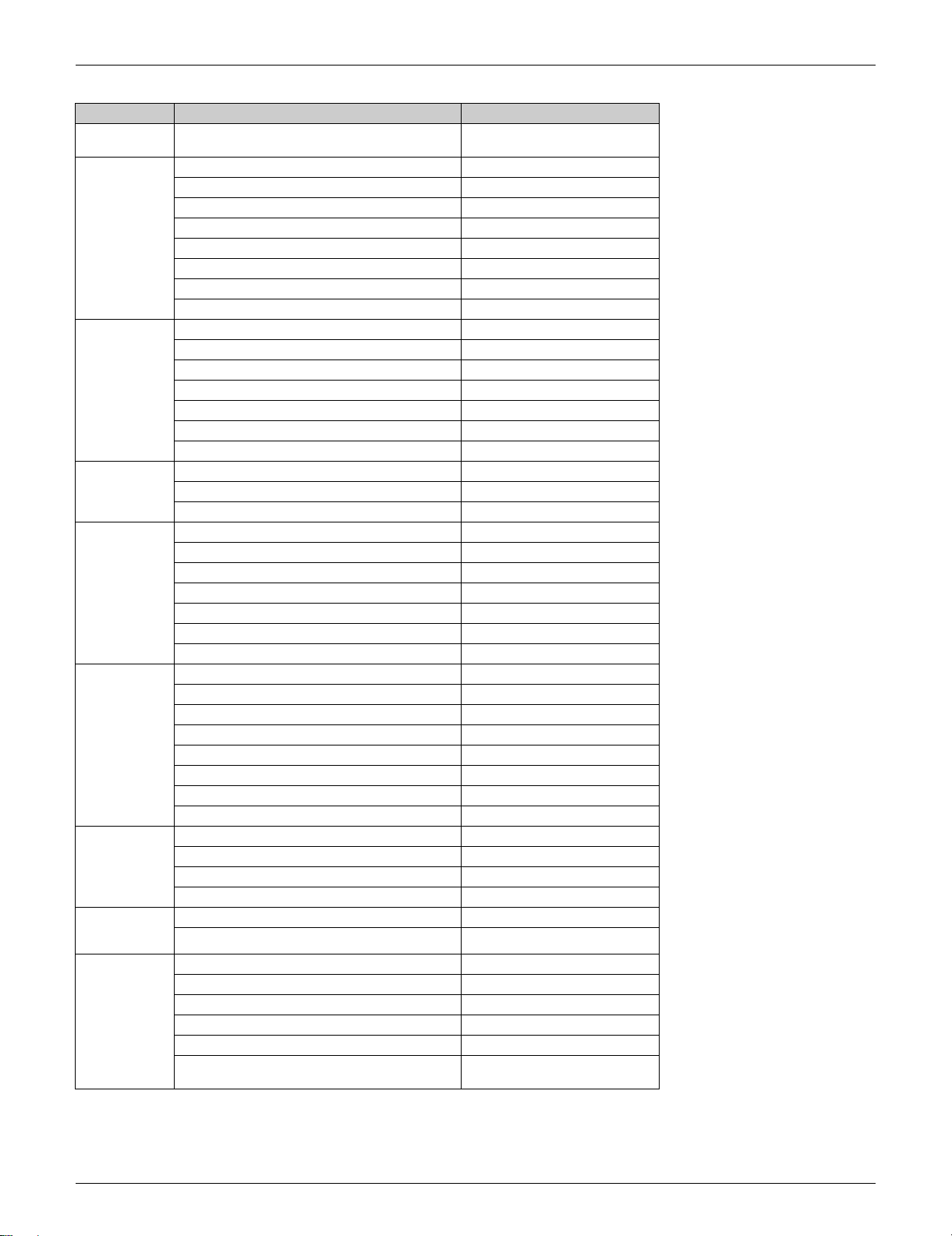
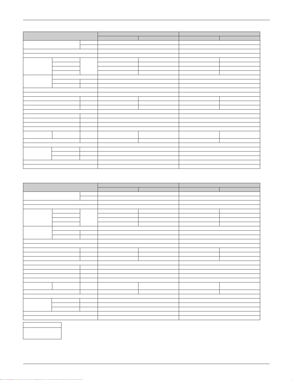
2. Functions
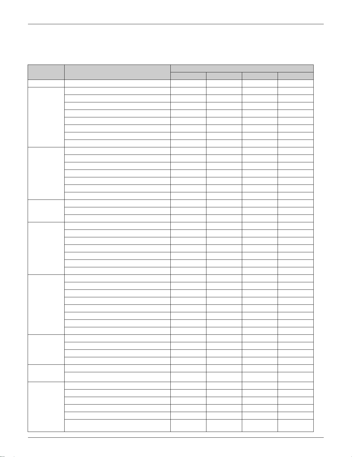
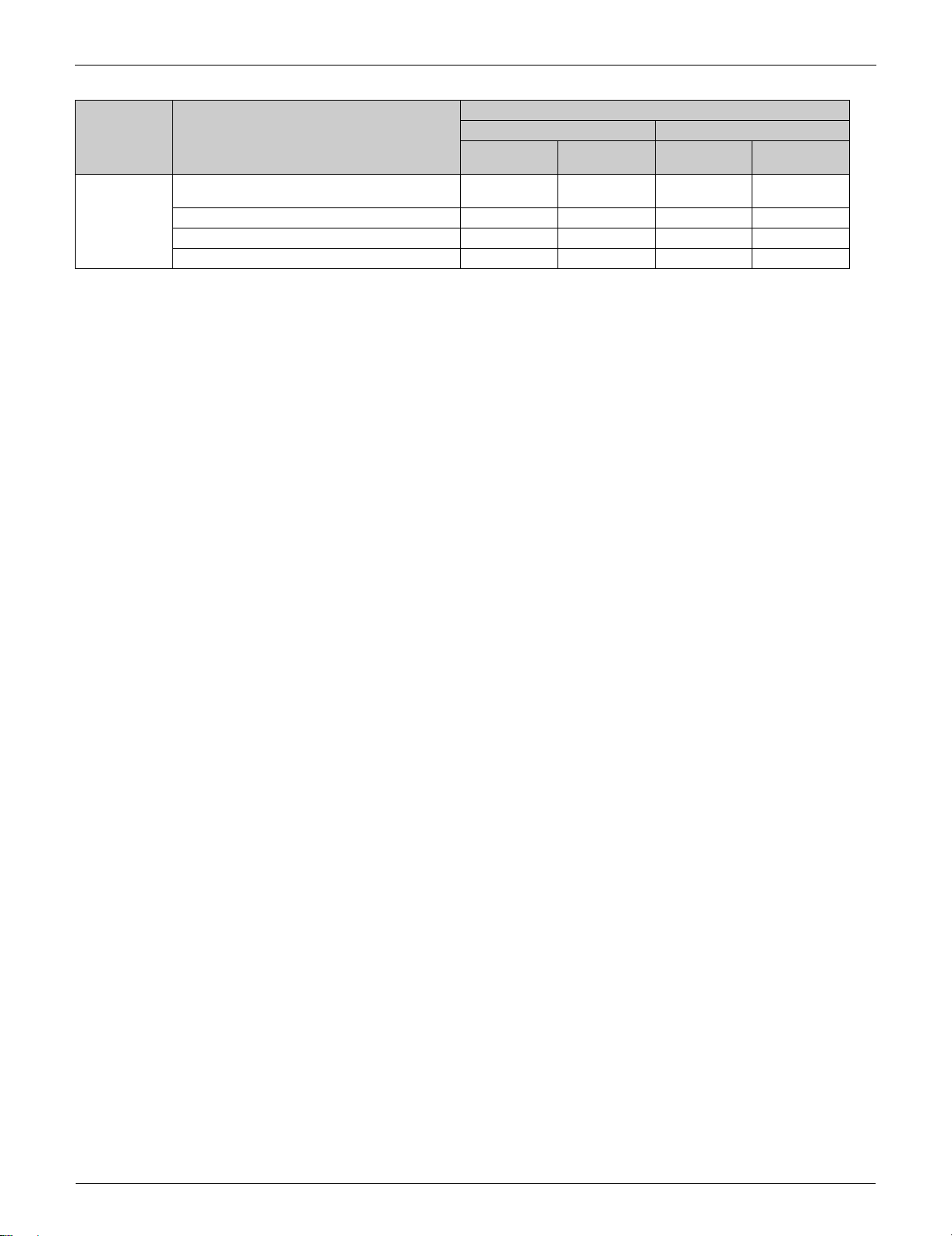
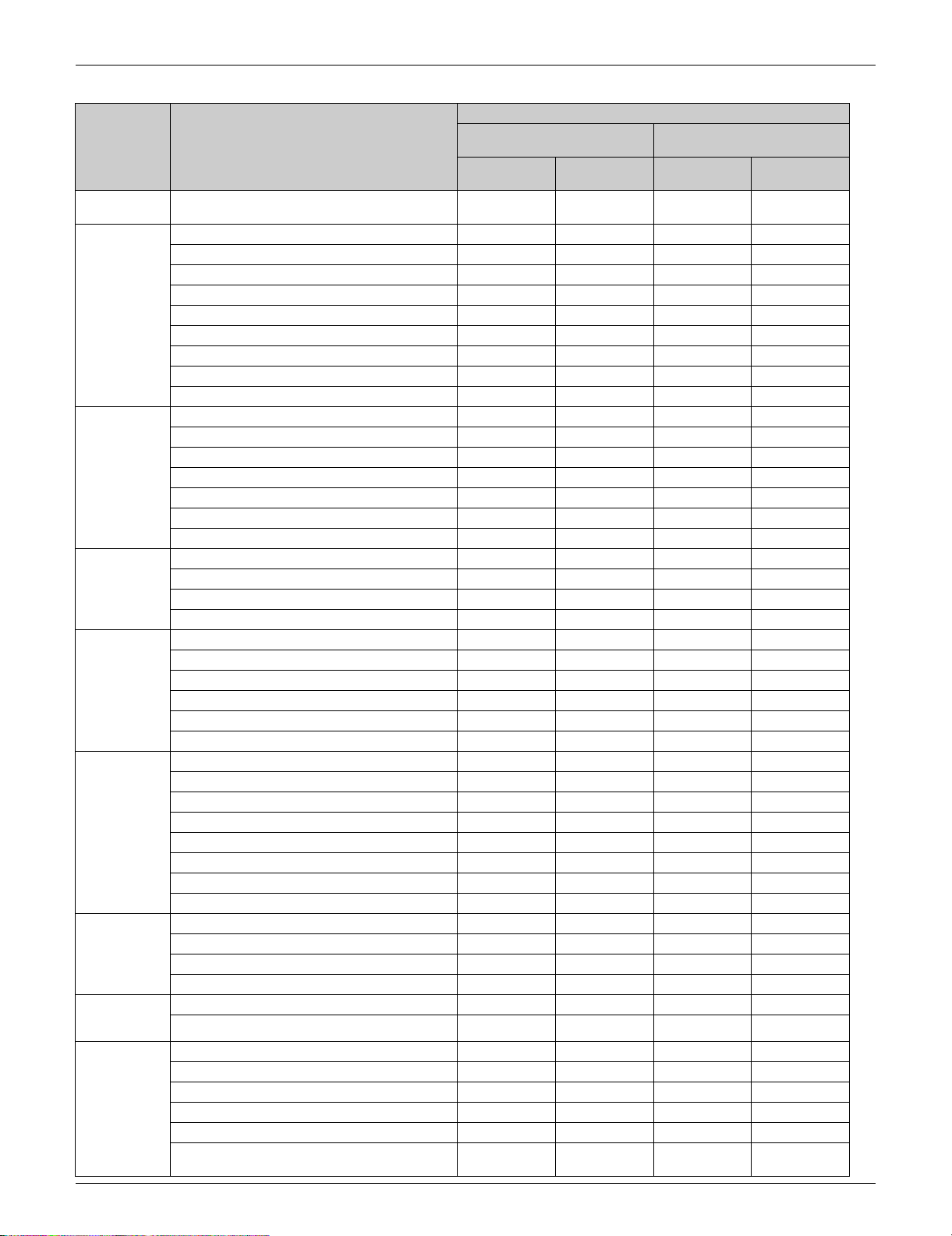
2.1 RA Indoor Unit
Category Functions
Basic Function Inverter (with inverter power control)
Comfortable
Airflow
Comfort
Control
Operation Automatic cooling/heating changeover
Lifestyle
Convenience
Health and
Cleanliness
Timer WEEKLY TIMER operation
Worry Free
(Reliability &
Durability)
Flexibility Multi-split/split type compatible indoor unit ——
Power-airflow flap (horizontal blade) — — — —
Power-airflow dual flaps (horizontal blade)
Power-airflow diffuser — — — —
Wide-angle louvers (vertical blades)
Auto-swing (up and down)
Auto-swing (right and left)
3-D airflow
COMFORT AIRFLOW operation
Auto fan speed
Indoor unit quiet operation
NIGHT QUIET mode (automatic) — — — —
OUTDOOR UNIT QUIET operation (manual)
INTELLIGENT EYE operation — —
2-area INTELLIGENT EYE operation ——
Hot-start function
Program dry operation
Fan only
POWERFUL operation (inverter)
HOME LEAVE operation — — — —
ECONO operation
Indoor unit ON/OFF switch
Signal receiving sign
R/C with back light
Temperature display — — — —
Air-purifying filer — — — —
Titanium apatite deodorizing filter Option Option
Longlife filter — — — —
Air filter (prefilter)
Wipe-clean flat panel
Washable grille — — — —
Filter cleaning indicator — — — —
Good-sleep cooling operation — — — —
24-hour ON/OFF TIMER
72-hour ON/OFF TIMER — — — —
NIGHT SET mode
Auto-restart (after power failure)
Self-diagnosis (R/C, LED)
Flexible power supply correspondence — — — —
High ceiling application — — — —
Either side drain (right or left)
Power selection — — — —
°F/°C changeover R/C temperature display
(factory setting: °F)
FTXR CTXG CTXS FTXS
Wall Mounted (Non Duct) Type
Part 1 General Information 11
Functions SiUS121827E
Category Functions
Remote
Control
Remote
Controller
—: Available
: Not available
Remote control adaptor
(normal open pulse contact)
Remote control adaptor (normal open contact) Option Option Option Option
DIII-NET compatible (adaptor) Option Option Option Option
Wireless LAN connection Option Option Option Option
Wireless
Wired Option Option Option Option
Wall Mounted (Non Duct) Type
FTXR CTXG CTXS FTXS
Option Option Option Option
12 Part 1 General Information
SiUS121827E Functions
L.S.P. Duct Connected Type
Category Functions
wired R/C
Basic Function Inverter (with inverter power control)
Comfortable
Airflow
Comfort
Control
Operation Automatic cooling/heating changeover
Lifestyle
Convenience
Health and
Cleanliness
Timer WEEKLY TIMER operation — — — —
Worry Free
(Reliability &
Durability)
Flexibility Multi-split/split type compatible indoor unit ——
Power-airflow flap (horizontal blade) — — — —
Power-airflow dual flaps (horizontal blade) — — — —
Power-airflow diffuser — — — —
Wide-angle louvers (vertical blades) — — — —
Auto-swing (up and down) — — — —
Auto-swing (right and left) — — — —
3-D airflow ————
COMFORT AIRFLOW operation — — — —
Switchable fan speed
Auto fan speed
Indoor unit quiet operation
NIGHT QUIET mode (automatic) — — — —
OUTDOOR UNIT QUIET operation (manual) — —
INTELLIGENT EYE operation — — — —
2-area INTELLIGENT EYE operation — — — —
Hot-start function
Program dry operation
Fan only — —
POWERFUL operation (inverter) — —
HOME LEAVE operation — — — —
ECONO operation — —
Indoor unit ON/OFF switch
Signal receiving sign
R/C with back light
Temperature display — — — —
Air-purifying filer — — — —
Titanium apatite deodorizing filter — — — —
Longlife filter — — — —
Air filter (prefilter)
Wipe-clean flat panel — — — —
Washable grille — — — —
Filter cleaning indicator — — — —
Good-sleep cooling operation — — — —
24-hour ON/OFF TIMER
72-hour ON/OFF TIMER — — — —
NIGHT SET mode
Auto-restart (after power failure)
Self-diagnosis (R/C, LED)
Flexible power supply correspondence — — — —
High ceiling application — — — —
Either side drain (right or left) — — — —
Power selection ————
°F/°C changeover R/C temperature display
(factory setting: °F)
FDXS CDXS
With
With
wireless R/C
With
wired R/C
With
wireless R/C
Part 1 General Information 13
Functions SiUS121827E
L.S.P. Duct Connected Type
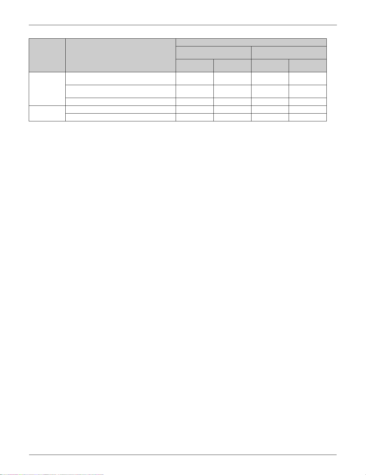
Category Functions
Remote
Control
—: Available
: Not available
Remote control adaptor
(normal open pulse contact)
Remote control adaptor (normal open contact) Option Option Option Option
DIII-NET compatible (adaptor) Option Option Option Option
Wireless LAN connection — — — —
wired R/C
Option Option Option Option
FDXS CDXS
With
With
wireless R/C
With
wired R/C
With
wireless R/C
14 Part 1 General Information
SiUS121827E Functions
Category Functions Floor Standing Type FVXS
Basic Function Inverter
Comfortable
Airflow
Comfort
Control
Operation Automatic cooling/heating changeover
Lifestyle
Convenience
Health and
Cleanliness
Timer WEEKLY TIMER operation
Worry Free
(Reliability &
Durability)
Flexibility Multi-split/split type compatible indoor unit
(with inverter power control)
Power-airflow flap (horizontal blade) —
Power-airflow dual flaps (horizontal blade) —
Power-airflow diffuser —
Wide-angle louvers (vertical blades)
Auto-swing (up and down)
Auto-swing (right and left) —
3-D airflow —
COMFORT AIRFLOW operation —
Auto fan speed
Indoor unit quiet operation
NIGHT QUIET mode (automatic) —
OUTDOOR UNIT QUIET operation (manual)
INTELLIGENT EYE operation —
2-area INTELLIGENT EYE operation —
Hot-start function
Program dry operation
Fan only
POWERFUL operation (inverter)
HOME LEAVE operation —
ECONO operation
Indoor unit ON/OFF switch
Signal receiving sign
R/C with back light
Temperature display —
Air-purifying filer —
Titanium apatite deodorizing filter
Longlife filter —
Air filter (prefilter)
Wipe-clean flat panel
Washable grille —
Filter cleaning indicator —
Good-sleep cooling operation —
24-hour ON/OFF TIMER
72-hour ON/OFF TIMER —
NIGHT SET mode
Auto-restart (after power failure)
Self-diagnosis (R/C, LED)
Flexible power supply correspondence —
High ceiling application —
Either side drain (right or left) —
Power selection —
°F/°C changeover R/C temperature display
(factory setting: °F)
Part 1 General Information 15

Functions SiUS121827E
Category Functions Floor Standing Type FVXS
Remote
Control
Remote
Controller
—: Available
: Not available
Remote control adaptor
(normal open pulse contact)
Remote control adaptor (normal open contact) Option
DIII-NET compatible (adaptor) Option
Wireless LAN connection Option
Wireless
Wired —
Option
16 Part 1 General Information
SiUS121827E Functions
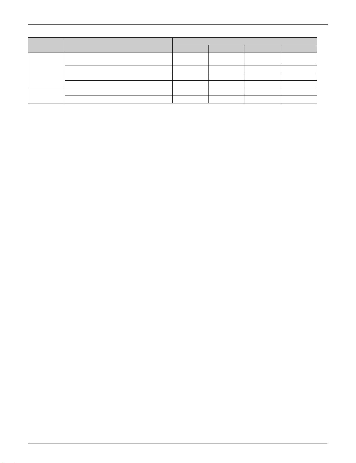
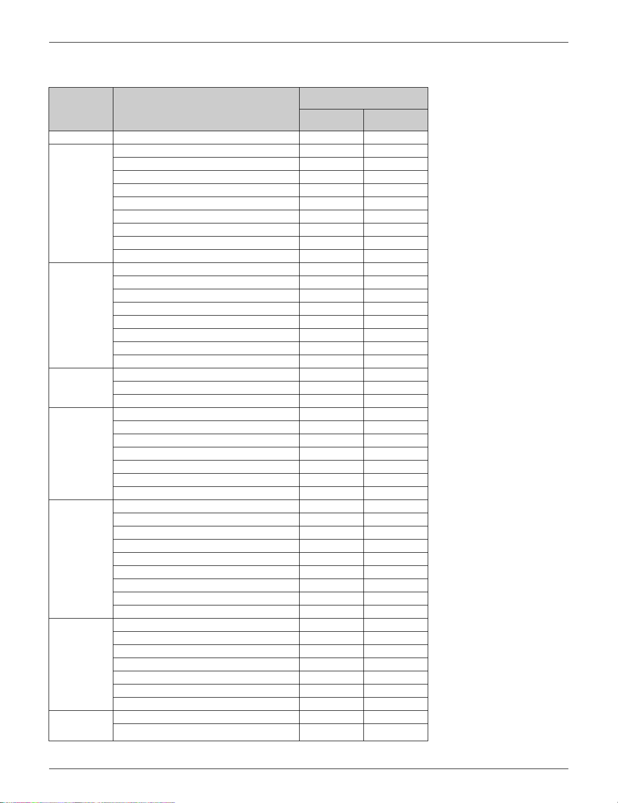
2.2 SA Indoor Unit
M.S.P. Duct Connected Type
Category Functions
wired R/C
Basic Function Inverter (with inverter power control)
Comfortable
Airflow
Comfort
Control
Operation Automatic cooling/heating changeover
Lifestyle
Convenience
Health and
Cleanliness
Timer Setpoint auto reset —
Worry Free
(Reliability &
Durability)
Power-airflow flap (horizontal blade) — —
Power-airflow dual flaps (horizontal blade) — —
Power-airflow diffuser — —
Wide-angle louvers (vertical blades) — —
Auto-swing (up and down) — —
Auto-swing (right and left) — —
3-D airflow — —
COMFORT AIRFLOW operation — —
Switchable fan speed (3 steps)
Auto fan speed —
Indoor unit quiet operation — —
NIGHT QUIET mode (automatic) — —
OUTDOOR UNIT QUIET operation (manual) — —
2 selectable temperature sensors —
INTELLIGENT EYE operation — —
2-area INTELLIGENT EYE operation — —
Hot-start function
Program dry operation
Fan only
POWERFUL operation (inverter) — —
HOME LEAVE operation — —
ECONO operation — —
Emergency operation switch —
Signal receiving sign —
R/C with back light —
Temperature display — —
Air-purifying filer — —
Titanium apatite deodorizing filter — —
Silver ion anti-bacterial drain pan
Longlife filter Option Option
Air filter — —
Filter cleaning indicator
Wipe-clean flat panel — —
Washable grille — —
Good-sleep cooling operation — —
Setpoint range restriction —
Schedule TIMER operation —
24-hour ON/OFF TIMER —
Count up/down ON/OFF TIMER —
Off Timer (turns unit off after set time) —
NIGHT SET mode — —
Auto-restart (after power failure)
Self-diagnosis (R/C, LED)
FDMQ
With
With
wireless R/C
Part 1 General Information 17
Functions SiUS121827E
M.S.P. Duct Connected Type
Category Functions
wired R/C
Flexibility Multi-split/split type compatible indoor unit
Flexible power supply correspondence — —
High ceiling application — —
Either side drain (right or left) — —
Drain pump
Power selection — —
°F/°C changeover R/C temperature display
(factory setting: °F)
Remote
Control
: Available
—
: Not available
: Receiving sound only
Remote control adaptor
(normal open pulse contact)
Remote control adaptor (normal open contact) — —
DIII-NET compatible (adaptor) Option Option
Wireless LAN connection — —
FDMQ
With
—
——
With
wireless R/C
18 Part 1 General Information
SiUS121827E Functions
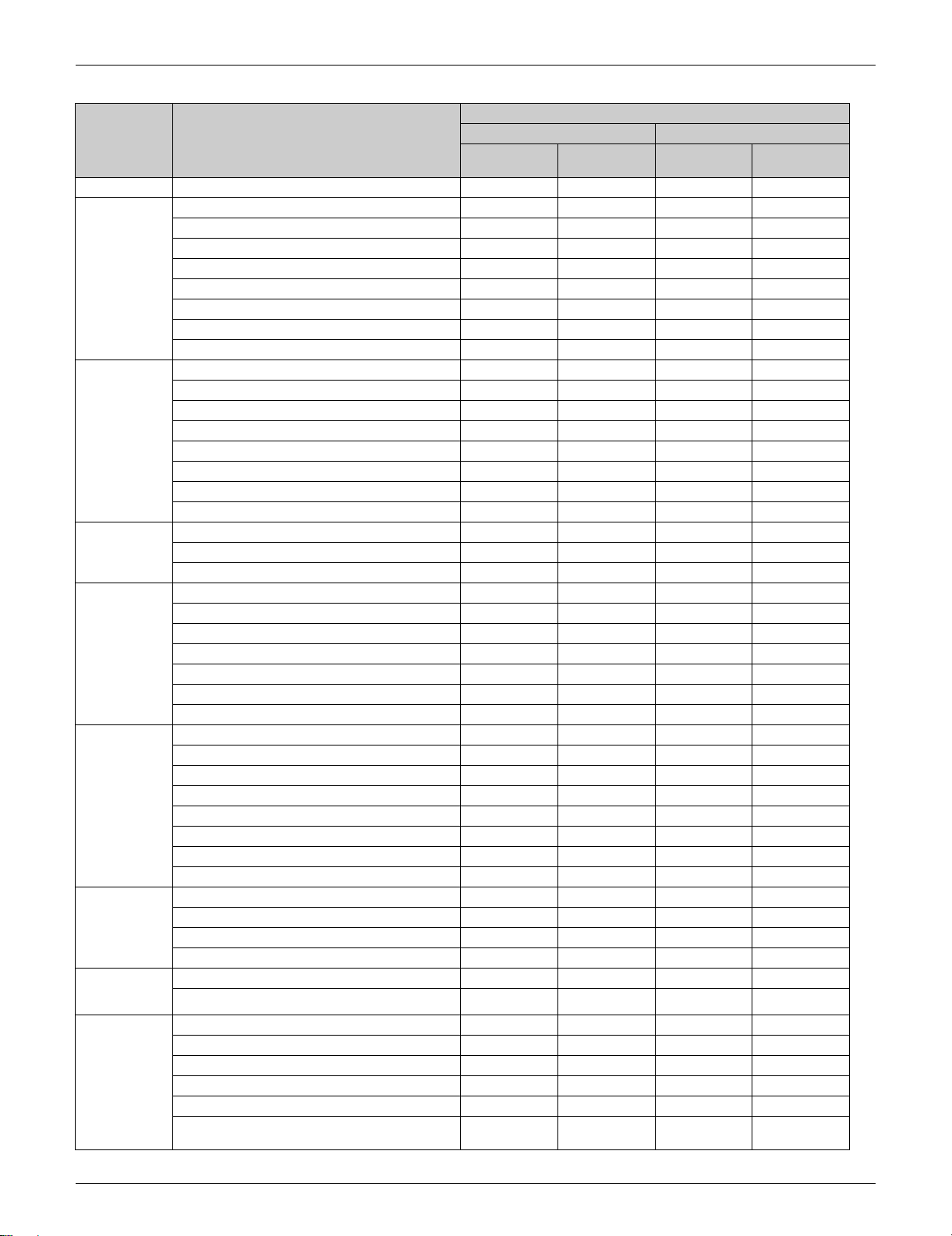
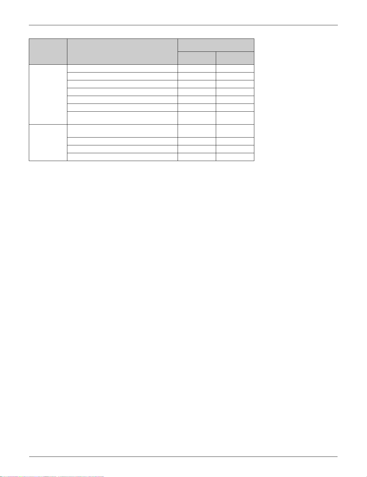
Ceiling Mounted Type FFQ
Decoration Panel
Category Functions
Basic
Function
Comfortable
Airflow
Comfort
Control
Operation Automatic cooling/heating changeover
Lifestyle
Convenience
Health and
Cleanliness
Timer Schedule TIMER operation — —
Worry Free
(Reliability &
Durability)
Flexibility Multi-split/split type compatible indoor unit
Inverter
(with inverter power control)
Power-airflow flap (horizontal blade) — — — —
Power-airflow dual flaps (horizontal blade) — — — —
Power-airflow diffuser — — — —
Wide-angle louvers (vertical blades) — — — —
Auto-swing (up and down)
Auto-swing (right and left) — — — —
Individual flap control — — —
3-D airflow — — — —
COMFORT AIRFLOW operation — — — —
Auto fan speed — —
Indoor unit quiet operation — — — —
NIGHT QUIET mode (automatic) — — — —
OUTDOOR UNIT QUIET operation (manual) — — — —
Presence and floor sensor — — Option —
Hot-start function
Draft prevention with sensor
Program dry operation
Fan only
Setback function — —
POWERFUL operation (inverter) — — — —
HOME LEAVE operation — — — —
ECONO operation — — — —
Emergency operation switch — —
Signal receiving sign — —
R/C with back light — —
Air-purifying filer — — — —
Titanium apatite deodorizing filter — — — —
Longlife filter Option Option Option Option
Air filter — — — —
Filter cleaning indicator
Wipe-clean flat panel — — — —
Washable grille
Good-sleep cooling operation — — — —
72-hour ON/OFF TIMER — —
Off Timer (turns unit off after set time) — —
NIGHT SET mode — — — —
Auto-restart (after power failure)
Self-diagnosis (R/C, LED)
Flexible power supply correspondence — — — —
Either side drain (right or left) — — — —
Drain pump
Power selection — — — —
°F/°C changeover R/C temperature display
cto
ry setting: °F)
(fa
BYFQ60B3W1
With
wired R/C
— —
With
wireless R/C
Decoration panel
BYFQ60C2W1W(S)
With
wired R/C
With
wireless R/C
Part 1 General Information 19
Functions SiUS121827E
Ceiling Mounted Type FFQ
Category Functions
Remote
Control
Remote
Controller
: Available
—
: Not available
: Receiving sound only
Remote control adaptor
(normal open pulse contact)
Remote control adaptor
(normal open contact)
DIII-NET compatible (adaptor) Option Option Option Option
Wireless Option Option Option Option
Wired Option Option Option Option
Decoration Panel
BYFQ60B3W1
With
wired R/C
————
————
With
wireless R/C
Decoration panel
BYFQ60C2W1W(S)
With
wired R/C
With
wireless R/C
20 Part 1 General Information
SiUS121827E Functions
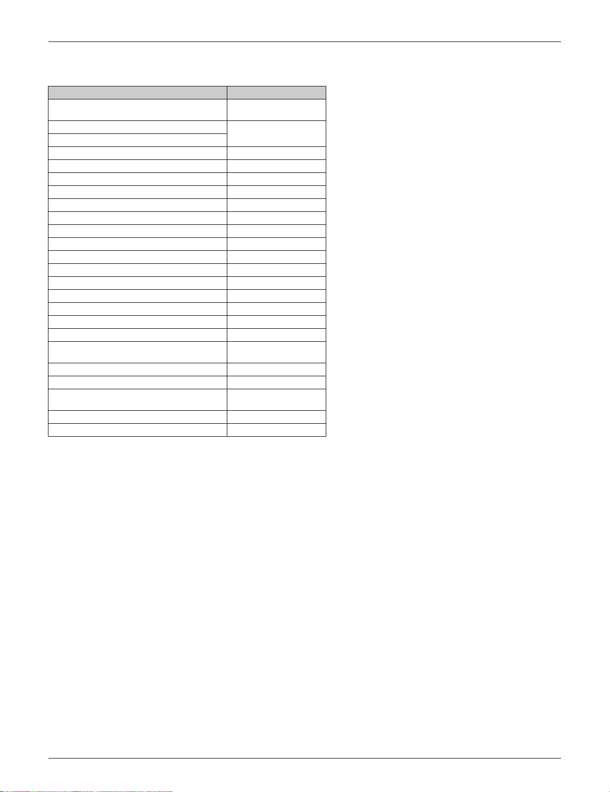
2.3 Outdoor Unit
Function 5MXS / 4MXL
Inverter
(with inverter power control)
Operation limit for cooling (°FDB)
Operation limit for heating (°FWB)
PAM control
Oval scroll compressor —
Swing compressor
Rotary compressor —
Reluctance DC motor
NIGHT QUIET mode
OUTDOOR UNIT QUIET operation
Quick warming function
Automatic defrosting
Defrost learning control
Priority room setting
COOL/HEAT mode lock
Auto-restart (after power failure) —
Self-diagnosis (R/C, LED)
Wiring error check function
Anti-corrosion treatment of outdoor heat
exchanger
Drain-pan heater control by microcomputer
Flexible power supply correspondence —
Chargeless 131.6 ft
Power selection —
Low temp. cooling operation (−15°C) (5°F) —
Refer to P.292
(40 m)
:
— :
Available
Not available
Part 1 General Information 21

SiUS121827E
Part 2
Specifications
1. Specifications ............................................................................................23
1.1 RA Indoor Unit............................................................................................ 23
1.2 SA Indoor Unit ............................................................................................ 31
1.3 Outdoor Unit ............................................................................................... 34
22 Part 2 Specifications
SiUS121827E Specifications
1. Specifications
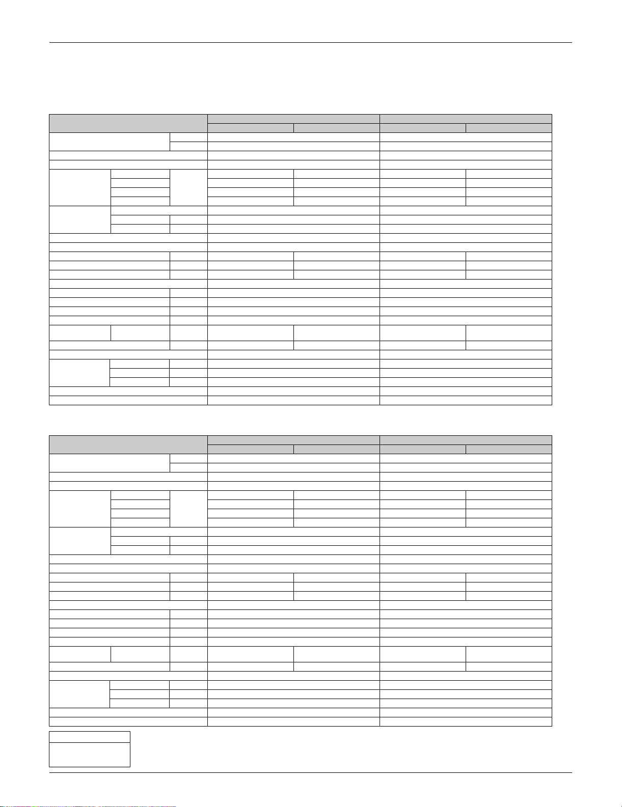
1.1 RA Indoor Unit
Model FTXR09TVJUW FTXR09TVJUWS
Power Supply Phase 1 φ 1 φ
Rated Capacity 9 kBtu/h Class 9 kBtu/h Class
Front Panel Color White Silver
Airflow Rates H
Fan Type Cross Flow Fan Cross Flow Fan
Air Direction Control Right, Left, Horizontal, Downward Right, Left, Horizontal, Downward
Air Filter Removable, Washable, Mildew Proof Removable, Washable, Mildew Proof
Running Current (Rated) A 0.07 - 0.07 0.13 - 0.12 0.07 - 0.07 0.13 - 0.12
Power Consumption (Rated) W 13 - 13 26 - 26 13 - 13 26 - 26
Power Factor (Rated) % 89.2 - 80.7 96.2 - 94.2 89.2 - 80.7 96.2 - 94.2
Temperature Control Microcomputer Control Microcomputer Control
Dimensions (H × W × D) in. (mm) 11-15/16 × 39-5/16 × 8-3/8 (303 × 998 × 212) 11-15/16 × 39-5/16 × 8-3/8 (303 × 998 × 212)
Packaged Dimensions (H × W × D) in. (mm) 12-11/16 × 43-3/8 × 15-5/16 (322 × 1,101 × 389) 12-11/16 × 43-3/8 × 15-5/16 (322 × 1,101 × 389)
Weight (Mass) Lbs (kg) 27 (12) 27 (12)
Gross Weight (Gross Mass) Lbs (kg) 36 (16) 36 (16)
Sound Pressure
Level
Sound Power Level dB — — — —
Heat Insulation Both Liquid and Gas Pipes Both Liquid and Gas Pipes
Piping Connection Liquid in. (mm) φ 1/4 (φ 6.4) φ 1/4 (φ 6.4)
Drawing No. 3D120044 3D120044
Notes 1. SL: The quiet fan level of the airflow rate setting. 1. SL: The quiet fan level of the airflow rate setting.
M 208 (5.9) 258 (7.3) 208 (5.9) 258 (7.3)
L 162 (4.6) 201 (5.7) 162 (4.6) 201 (5.7)
SL 134 (3.8) 117 (3.3) 134 (3.8) 117 (3.3)
Motor Output W 29 29
Speed Steps 5 Steps, Quiet, Auto 5 Steps, Quiet, Auto
H / M / L / SL
Gas in. (mm) φ 3/8 (φ 9.5) φ 3/8 (φ 9.5)
Drain in. (mm) φ 11/16 (φ 18) φ 11/16 (φ 18)
Hz, V 60 Hz, 208 - 230 V 60 Hz, 208 - 230 V
cfm
3
/min)
(m
dB(A) 38 / 32 / 25 / 19 41 / 34 / 28 / 19 38 / 32 / 25 / 19 41 / 34 / 28 / 19
Cooling Heating Cooling Heating
272 (7.7) 346 (9.8) 272 (7.7) 346 (9.8)
Model FTXR12TVJUW FTXR12TVJUS
Power Supply Phase 1 φ 1 φ
Rated Capacity 12 kBtu/h Class 12 kBtu/h Class
Front Panel Color White Silver
Airflow Rates H
Fan Type Cross Flow Fan Cross Flow Fan
Air Direction Control Right, Left, Horizontal, Downward Right, Left, Horizontal, Downward
Air Filter Removable, Washable, Mildew Proof Removable, Washable, Mildew Proof
Running Current (Rated) A 0.13 - 0.12 0.19 - 0.17 0.13 - 0.12 0.19 - 0.17
Power Consumption (Rated) W 26 - 26 38 - 38 26 - 26 38 - 38
Power Factor (Rated) % 96.1 - 94.2 96.1 - 97.1 96.1 - 94.2 96.1 - 97.1
Temperature Control Microcomputer Control Microcomputer Control
Dimensions (H × W × D) in. (mm) 11-15/16 × 39-5/16 × 8-3/8 (303 × 998 × 212) 11-15/16 × 39-5/16 × 8-3/8 (303 × 998 × 212)
Packaged Dimensions (H × W × D) in. (mm) 12-11/16 × 43-3/8 × 15-5/16 (322 × 1,101 × 389) 12-11/16 × 43-3/8 × 15-5/16 (322 × 1,101 × 389)
Weight (Mass) Lbs (kg) 27 (12) 27 (12)
Gross Weight (Gross Mass) Lbs (kg) 36 (16) 36 (16)
Sound Pressure
Level
Sound Power Level dB — — — —
Heat Insulation Both Liquid and Gas Pipes Both Liquid and Gas Pipes
Piping Connection Liquid in. (mm) φ 1/4 (φ 6.4) φ 1/4 (φ 6.4)
Drawing No. 3D120044 3D120044
Notes 1. SL: The quiet fan level of the airflow rate setting. 1. SL: The quiet fan level of the airflow rate setting.
Conversion Formulae
kcal/h = kW × 860
Btu/h = kW × 3412
cfm = m³/min × 35.3
M 219 (6.2) 290 (8.2) 219 (6.2) 290 (8.2)
L 169 (4.8) 226 (6.4) 169 (4.8) 226 (6.4)
SL 131 (3.7) 131 (3.7) 131 (3.7) 131 (3.7)
Motor Output W 29 29
Speed Steps 5 Steps, Quiet, Auto 5 Steps, Quiet, Auto
H / M / L / SL
Gas in. (mm) φ 3/8 (φ 9.5) φ 3/8 (φ 9.5)
Drain in. (mm) φ 11/16 (φ 18) φ 11/16 (φ 18)
Hz, V 60 Hz, 208 - 230 V 60 Hz, 208 - 230 V
cfm
3
/min)
(m
dB(A) 45 / 34 / 26 / 20 45 / 37 / 29 / 20 45 / 34 / 26 / 20 45 / 37 / 29 / 20
Cooling Heating Cooling Heating
335 (9.5) 395 (11.2) 335 (9.5) 395 (11.2)
Part 2 Specifications 23
Specifications SiUS121827E
Model FTXR18TVJUW FTXR18TVJUS
Power Supply Phase 1 φ 1 φ
Rated Capacity 18 kBtu/h Class 18 kBtu/h Class
Front Panel Color White Silver
Airflow Rates H
Fan Type Cross Flow Fan Cross Flow Fan
Air Direction Control Right, Left, Horizontal, Downward Right, Left, Horizontal, Downward
Air Filter Removable, Washable, Mildew Proof Removable, Washable, Mildew Proof
Running Current (Rated) A 0.14 - 0.14 0.21 - 0.21 0.14 - 0.14 0.21 - 0.21
Power Consumption (Rated) W 28 - 28 42 - 42 28 - 28 42 - 42
Power Factor (Rated) % 96.1 - 87.0 96.2 - 87.0 96.1 - 87.0 96.2 - 87.0
Temperature Control Microcomputer Control Microcomputer Control
Dimensions (H × W × D) in. (mm) 11-15/16 × 39-5/16 × 8-3/8 (303 × 998 × 212) 11-15/16 × 39-5/16 × 8-3/8 (303 × 998 × 212)
Packaged Dimensions (H × W × D) in. (mm) 12-11/16 × 43-3/8 × 15-5/16 (322 × 1,101 × 389) 12-11/16 × 43-3/8 × 15-5/16 (322 × 1,101 × 389)
Weight (Mass) Lbs (kg) 27 (12) 27 (12)
Gross Weight (Gross Mass) Lbs (kg) 36 (16) 36 (16)
Sound Pressure
Level
Sound Power Level dB — — — —
Heat Insulation Both Liquid and Gas Pipes Both Liquid and Gas Pipes
Piping Connection Liquid in. (mm) φ 1/4 (φ 6.4) φ 1/4 (φ 6.4)
Drawing No. 3D120048A 3D120048A
Notes 1. SL: The quiet fan level of the airflow rate setting. 1. SL: The quiet fan level of the airflow rate setting.
M 275 (7.8) 332 (9.4) 275 (7.8) 332 (9.4)
L 226 (6.4) 275 (7.8) 226 (6.4) 275 (7.8)
SL 208 (5.9) 208 (5.9) 208 (5.9) 208 (5.9)
Motor Output W 29 29
Speed Steps 5 Steps, Quiet, Auto 5 Steps, Quiet, Auto
H / M / L / SL
Gas in. (mm) φ 1/2 (φ 12.7) φ 1/2 (φ 12.7)
Drain in. (mm) φ 11/16 (φ 18) φ 11/16 (φ 18)
Hz, V 60 Hz, 208 - 230 V 60 Hz, 208 - 230 V
cfm
3
(m
/min)
dB(A) 46 / 40 / 35 / 30 47 / 41 / 35 / 30 46 / 40 / 35 / 30 47 / 41 / 35 / 30
Cooling Heating Cooling Heating
350 (9.9) 413 (11.7) 350 (9.9) 413 (11.7)
Model CTXG09QVJUW CTXG09QVJUS
Power Supply Phase 1 φ 1 φ
Rated Capacity 9 kBtu/h Class 9 kBtu/h Class
Front Panel Color White Silver
Airflow Rates H
Fan Type Cross Flow Fan Cross Flow Fan
Air Direction Control Right, Left, Horizontal, Downward Right, Left, Horizontal, Downward
Air Filter Removable, Washable, Mildew Proof Removable, Washable, Mildew Proof
Running Current (Rated) A 0.07 - 0.07 0.13 - 0.12 0.07 - 0.07 0.13 - 0.12
Power Consumption (Rated) W 13 - 13 26 - 26 13 - 13 26 - 26
Power Factor (Rated) % 89.2 - 80.7 96.2 - 94.2 89.2 - 80.7 96.2 - 94.2
Temperature Control Microcomputer Control Microcomputer Control
Dimensions (H × W × D) in. (mm) 11-15/16 × 39-5/16 × 8-3/8 (303 × 998 × 212) 11-15/16 × 39-5/16 × 8-3/8 (303 × 998 × 212)
Packaged Dimensions (H × W × D) in. (mm) 12-11/16 × 43-3/8 × 15-5/16 (322 × 1,101 × 389) 12-11/16 × 43-3/8 × 15-5/16 (322 × 1,101 × 389)
Weight (Mass) Lbs (kg) 27 (12) 27 (12)
Gross Weight (Gross Mass) Lbs (kg) 36 (16) 36 (16)
Sound Pressure
Level
Sound Power Level dB — — — —
Heat Insulation Both Liquid and Gas Pipes Both Liquid and Gas Pipes
Piping Connection Liquid in. (mm) φ 1/4 (φ 6.4) φ 1/4 (φ 6.4)
Drawing No. 3D105562 3D105565
Notes 1. SL: The quiet fan level of the airflow rate setting. 1. SL: The quiet fan level of the airflow rate setting.
Conversion Formulae
kcal/h = kW × 860
Btu/h = kW × 3412
cfm = m³/min × 35.3
M 212 (6.0) 265 (7.5) 212 (6.0) 265 (7.5)
L 162 (4.6) 205 (5.8) 162 (4.6) 205 (5.8)
SL 134 (3.8) 117 (3.3) 134 (3.8) 117 (3.3)
Motor Output W 29 29
Speed Steps 5 Steps, Quiet, Auto 5 Steps, Quiet, Auto
H / M / L / SL
Gas in. (mm) φ 3/8 (φ 9.5) φ 3/8 (φ 9.5)
Drain in. (mm) φ 11/16 (φ 18) φ 11/16 (φ 18)
Hz, V 60 Hz, 208 - 230 V 60 Hz, 208 - 230 V
cfm
3
/min)
(m
dB(A) 38 / 32 / 25 / 21 41 / 34 / 28 / 21 38 / 32 / 25 / 21 41 / 34 / 28 / 21
Cooling Heating Cooling Heating
279 (7.9) 367 (10.4) 279 (7.9) 367 (10.4)
24 Part 2 Specifications
 Loading...