


INSTALLATION AND
OPERATION MANUAL
Air conditioning system
Installation and operation manual
Air conditioning system
Installations- und Bedienungsanleitung
Klimaanlagensystem
Manuel d'installation et d'utilisation
Système de conditionnement d’air
Montagehandleiding en gebruiksaanwijzing
Airconditioningsysteemr
Manual de instalación y operación
Sistema de aire acondicionado
Manuale di installazione e d'uso
Sistema di climatizzazione
∂Б¯ВИЪ›‰ИФ ВБО·Щ¿ЫЩ·ЫЛ˜ О·И ПВИЩФ˘ЪБ›·˜
™‡ЫЩЛМ· ОПИМ·ЩИЫМФ‡
Manual de instalação e de operações
Sistema de ar condicionado
English
Deutsch
Français
Nederlands
Español
Italiano
EППЛУИО¿
Portugues
FMCQ50A7VEB
FMCQ60A7VEB
FMCQ71A7VEB
FMCQ100A7VEB
FMCQ125A7VEB
Инструкция по монтажу и эксплуатации
Система кондиционирования воздуха
Montaj ve kullanım kılavuzu
Klima sistemi
русский
Türkçe

ATITIKTIES-DEKLARACIJA
ATBILSTĪBAS-DEKLARĀCIJA
VYHLÁSENIE-ZHODY
CE -
CE -
CE -
CE - UYUMLULUK-BİLDİRİSİ
ZJAVA O SKLADNOSTI
VASTAVUSDEKLARATSIOON
ДЕКЛАРАЦИЯ-ЗА-СЪОТВЕТСТВИЕ
CE - I
CE -
CE -
deklaruje na własną i wyłączną odpowiedzialność, że modele klimatyzatorów, których dotyczy niniejsza deklaracja:
declară pe proprie răspundere că aparatele de aer cond ţionat la care se referă această declaraţie:
z vso odgovornostjo izjav ja, da so modeli klimatskih naprav, na katere se izjava nanaša:
kinnitab oma täielikul vastutusel, et käesoleva deklaratsiooni alla kuuluvad kliimaseadmete mudelid:
m
r
o
x
17
18
19
20
IZJAVA-O-USKLAĐENOSTI
DEKLARACJA-ZGODNOŚCI
DECLARAŢIE-DE-CONFORMITATE
CE - MEGFELELŐSÉGI-NYILATKOZAT
CE -
CE -
CE -
PROHLÁŠENÍ-O-SHODĚ
CE - ERKLÆRING OM-SAMSVAR
CE - ILMOITUS-YHDENMUKAISUUDESTA
CE -
Direktive z vsemi spremembami.
Direktiivid koos muudatustega.
Директиви, с техните изменения.
Direktyvose su pap ldymais.23Direktīvās un to papildinājumos.
Smernice, v platnom znení.
19
20
Direktiver, med senere ændringer.11Direktiv, med företagna ändringar.12Direktiver, med foretatte endringer.13Direktiivejä, sellaisina kuin ne ovat muutettuina.
10
декларира на своя отговорност, че моделите климатична инсталация, за които се отнася тази декларация:
visiška savo atsakomybe skelbia, kad oro kondicionavimo prietaisų modeliai, kuriems yra taikoma ši deklaracija:
ar pilnu atbildību apliecina, ka tālāk uzskaitīto modeĮu gaisa kondicionētāji, uz kuriem attiecas šī deklarācija:
vyhlasuje na vlastnú zodpovednosť, že tieto klimatizačné modely, na ktoré sa vzťahuje toto vyhlásenie:
b
21
tamamen kendi sorumluluğunda olmak üzere bu bildirinin ilgili olduğu klima modellerinin aşağıdaki gibi olduğunu beyan eder:
w
t
v
k
22
23
24
25
megfelelnek az alábbi szabvány(ok)nak vagy egyéb irányadó dokumentum(ok)nak, ha azokat előírás szerint használják:
spełniają wymogi następujących norm i innych dokumentów normalizacyjnych, pod warunkiem że używane są zgodnie z naszymi
instrukcjami:
sunt în conformitate cu următorul (următoarele) standard(e) sau alt(e) document(e) normativ(e), cu condiţia ca acestea să fie utilizate în
conformitate cu instrucţiunile noastre
skladni z naslednjimi standardi in drugimi normativi, pod pogojem, da se uporabljajo v skladu z našimi navodili:
on vastavuses järgmis(t)e standardi(te)ga või teiste normatiivsete dokumentidega, kui neid kasutatakse vastavalt meie juhenditele:21съответстват на следните стандарти или други нормативни документи, при условие, че се използват съгласно нашите
инструкции:22atitinka žemiau nurodytus standartus ir (arba) kitus norminius dokumentus su sąlyga, kad yra naudojami pagal mūsų nurodymus:
tad, ja lietoti atbilstoši ražotāja norādījumiem, atbilst sekojošiem standartiem un citiem normatīviem dokumentiem:
sú v zhode s nasledovnou(ými) normou(ami) alebo iným(i) normatívnym(i) dokumentom(ami), za predpokladu, že sa používajú v súlade
s našim návodom:
16
17
18
19
20
ürünün, talimatlarımıza göre ku lanılması koşuluyla aşağıdaki standartlar ve norm belirten belgelerle uyumludur:
23
24
25
Directives, as amended.
Direktiven, gemäß Änderung.03Directives, telles que modifiées.04Richtlijnen, zoals geamendeerd.
01
02
Değiştirilmiş halleriyle Yönetmelikler.
21
22
24
25
v platném znění.
Smjernice, kako je izmijenjeno.
irányelv(ek) és módosításaik rendelkezéseit.
z późniejszymi poprawkami.
Directivelor, cu amendamentele respective.
14
15
16
17
18
Directivas, según lo enmendado.
Direttive, come da modifica.07√‰ËÁÈÒv, fiˆ˜ ¤¯Ô˘Ó ÙÚÔÔÔÈËı›.
Directivas, conforme alteração em.
Директив со всеми поправками.
05
06
08
09
Machinery 98/37/EC
Low Voltage 2006/95/EC
Electromagnetic Compatibility 2004/108/EC *
<A> DAIKIN.TCF.024C22/07-2008
v
<B>
<B>
.
pozitīvajam
и оценено
<A>
както е изложено в
21 Забележка *
igazolta a megfelelést,
<B>
alapján, a(z)
<A>
a(z)
16 Megjegyzés *
enligt
<B>
och godkänts av
<A>
enligt
<B>
a pozitívne zistené
съгласно
<B>
положително от
szerint.
<C> tanúsítvány
a(z)
.
Certifikatet <C>
sertifikātu <C>
.
.
Cертификата <C>
, pozytywną opinią
<A>
zgodnie z dokumentacją
17 Uwaga *
og gjennom positiv
<A>
som det fremkommer i
<A>
ir kaip teigiamai nuspręsta
un atbilstoši
<A>
<A>
Sertifikatą <C>
pagal
kaip nustatyta
kā norādīts
ako bolo uvedené v
vērtējumam saskaņā ar
22 Pastaba *
23 Piezīmes *
24 Poznámka *
v
.
<B>
şi apreciat poz tiv
Certificatul <C>
.
.
<A>
in odobreno s strani
<A>
certifikatom <C>
în conformitate cu
Świadectwem <C>
i
<B>
de
skladu s
<B>
aşa cum este stabilit în
kot je določeno v
Notă *
18
19 Opomba *
v
on
<B>
.
<B>
ja jotka
mukaisesti.
<A>
.
Sertifikat <C>
a pozitivně zjištěno
ifølge
<A>
<B>
Sertifikaatin <C>
osvědčením <C>
bedømmelse av
jotka on esitetty asiakirjassa
jak bylo uvedeno v
hyväksynyt
souladu s
<B> TÜV (NB1856)
<C> 0510260101
<C> Sertifikasına
.
tarafından olumlu olarak
<B>
osvedčením <C>
‘da belirt ldiği g bi ve
değerlendirildiği gibi.
súlade s
<A>
göre
*
Not
25
.
ja heaks
<A>
sertifikaadile <C>
järgi vastavalt
<B>
kiidetud
nagu on näidatud dokumendis
*
20 Märkus
.
i poz tivno ocijenjeno od
Certifikatu <C>
<A>
prema
<B>
kako je izloženo u
strane
заявляет, исключительно под свою ответственность, что модели кондиционеров воздуха, к которым относится настоящее заявление:
erklærer under eneansvar, at klimaanlægmodellerne, som denne deklaration vedrører:
u
q
09
10
CE - DECLARAÇÃO-DE-CONFORMIDADE
СЕ - ЗАЯВЛЕНИЕ-О-СООТВЕТСТВИИ
CE - OPFYLDELSESERKLÆRING
CE - FÖRSÄKRAN-OM-ÖVERENSTÄMMELSE
CE - ¢H§ø™H ™YMMOPºø™H™
CE - DECLARACION-DE-CONFORMIDAD
CE - DICHIARAZIONE-DI-CONFORMITA
declares under its sole respons bility that the air conditioning models to which this declaration relates:
erklärt auf seine alleinige Verantwortung daß die Modelle der Klimageräte für die diese Erklärung bestimmt ist:
a
d
CE - DECLARATION-OF-CONFORMITY
CE - KONFORMITÄTSERKLÄRUNG
CE - DECLARATION-DE-CONFORMITE
CE - CONFORMITEITSVERKLARING
Daikin Europe N.V.
01
02
prohlašuje ve své plné odpovědnosti, že modely klimatizace, k nimž se toto prohlášení vztahuje:
izjav juje pod isključivo vlastitom odgovornošću da su modeli klima uređaja na koje se ova izjava odnosi:
deklarerar i egenskap av huvudansvarig, att luftkonditioneringsmodellerna som berörs av denna deklaration innebär att:
erklærer et fullstendig ansvar for at de luftkondisjoneringsmodeller som berøres av denne deklarasjon innebærer at:
s
n
11
12
déclare sous sa seule responsabilité que les appareils d'air conditionné visés par la présente déclaration:
verklaart hierbij op eigen exclusieve verantwoordel jkheid dat de airconditioning units waarop deze verklaring betrekking heeft:
f
l
03
04
teljes felelőssége tudatában kijelenti, hogy a klímaberendezés modellek, melyekre e nyilatkozat vonatkozik:
ilmoittaa yksinomaan omalla vastuullaan, että tämän ilmoituksen tarkoittamat ilmastointilaitteiden mallit:
j
c
y
h
13
14
15
16
declaración:
referencia la
declara baja su única responsabilidad que los modelos de aire acondicionado a los cuales hace
dichiara sotto sua responsabilità che i condizionatori modello a cui è r iferita questa dichiarazione:
‰ЛПТУВИ МВ ·ФОПВИЫЩ О‹ ЩЛ˜ В˘ı‡УЛ fiЩИ Щ· МФУЩ¤П· ЩˆУ ОПИМ·ЩИЫЩ ОТУ Ы˘ЫОВ˘ТУ ЫЩ· ФФ›· ·У·К¤ЪВЩ·И Л ·ЪФ‡Ы· ‰‹ПˆЫЛ:
declara sob sua exclusiva responsabilidade que os modelos de ar condicionado a que esta declaração se refere:
e
i
g
p
05
06
07
08
FMCQ50A7VEB*, FMCQ60A7VEB*, FMCQ71A7VEB*, FMCQ100A7VEB*, FMCQ125A7VEB*,
* = , , 1, 2, 3, ..., 9
estão em conformidade com a(s) seguinte(s) norma(s) ou outro(s) documento(s) nor mativo(s), desde que estes sejam utilizados de
acordo com as nossas instruções:09соответствуют следующим стандартам или другим нормативным документам, при условии их использования согласно нашим
инструкциям:10overholder følgende standard(er) eller andet/andre retningsgivende dokument(er), forudsat at disse anvendes i henhold til vore
instrukser:11respektive utrustning är utförd i överensstämmelse med och följer följande standard(er) eller andra normgivande dokument, under
förutsättning att användning sker i överensstämmelse med våra instruktioner:12respektive utstyr er i overensstemmelse med følgende standard(er) e ler andre nor mgivende dokument(er), under forutssetning av at
disse brukes i henhold til våre instrukser:13vastaavat seuraavien standardien ja muiden ohjeellisten dokumenttien vaatimuksia edellyttäen, että niitä käytetään ohjeidemme
mukaisesti:14za předpokladu, že jsou využívány v souladu s našimi pokyny, odpovídají následujícím normám nebo normativním dokumentům:
08
are in conformity with the following standard(s) or other normative document(s), provided that these are used in accordance with our
01
instructions:
der/den folgenden Norm(en) oder einem anderen Normdokument oder -dokumenten entspricht/entsprechen, unter der Voraussetzung,
daß sie gemäß unseren Anweisungen eingesetzt werden:03sont conformes à la/aux norme(s) ou autre(s) document(s) nor matif(s), pour autant qu'ils soient utilisés conformément à nos instructions:04conform de volgende norm(en) of één of meer andere bindende documenten zijn, op voorwaarde dat ze worden gebruikt overeenkomstig
02
onze instructies:05están en conformidad con la(s) siguiente(s) norma(s) u otro(s) documento(s) nor mativo(s), siempre que sean utilizados de acuerdo con
nuestras instrucciones:06sono conformi al(i) seguente(i) standard(s) o altro(i) documento(i) a carattere nor mativo, a patto che vengano usati in conformità alle
u skladu sa slijedećim standardom(ima) ili drugim normativnim dokumentom(ima), uz uvjet da se oni koriste u skladu s našim uputama:
15
nostre istruzioni:07В›У·И Ы‡МКˆУ· МВ ЩФ(·) ·ОfiПФ˘ıФ(·) ЪfiЩ˘Ф(·) ‹ ¿ППФ ¤ББЪ·КФ(·) О·УФУИЫМТУ, ˘fi ЩЛУ ЪФ¸fiıВЫЛ fiЩИ ¯ЪЛЫИМФФ Ф‡УЩ·И
Û‡Ìʈӷ Ì ÙȘ Ô‰ËÁ›Â˜ Ì·˜:
ob upoštevanju določb:
vastavalt nõuetele:
следвайки клаузите на:
laikantis nuostatų, pateikiamų:
ievērojot prasības, kas noteiktas:
održiavajúc ustanovenia:
19
20
under iagttagelse af bestemmelserne i:11enligt vil koren i:12gitt i henhold til bestemmelsene i:
10
following the provisions of:02gemäß den Vorschriften der:03conformément aux stipulations des:
01
EN60335-2-40,
bunun koşullarına uygun olarak:
21
22
23
24
25
noudattaen määräyksiä:
za dodržení ustanovení předpisu:
prema odredbama:
követi a(z):17zgodnie z postanowieniami Dyrektyw:
13
overeenkomstig de bepalingen van:05siguiendo las disposiciones de:
04
în urma prevederilor:
14
15
16
18
secondo le prescrizioni per:07Ì ًÚËÛË Ùˆv ‰È·Ù¿Íˆv Ùˆv:
de acordo com o previsto em:09в соответствии с положениями:
06
08
11 Information *
12 Merk *
13 Huom *
.
.
.
Certificado <C>
¶ИЫЩФФИЛЩИОfi <C>
e com o parecer
Î·È ÎÚ›ÓÂÙ·È ıÂÙÈο
<A>
<A>
Certificato <C>
e giudicato positivamente
<A>
delineato nel
06 Nota *
<B>
and judged positively by
<A>
as set out in
01 Note *
de acordo com o
Û‡Ìʈӷ Ì ÙÔ
<B>
<B>
secondo il
<B>
positivo de
da
tal como estabelecido em
·fi ÙÔ
* fiˆ˜ ηıÔÚ›˙ÂÙ·È ÛÙÔ
*
™ËÌ›ˆÛË
07
08 Nota
positiv
.
<B>
.
.
<C>
<C>
et évalué positivement par
Certificat <C>
<A>
Certificate
Zertifikat
aufgeführt und von
<A>
conformément au
wie in der
tel que défini dans
<B>
beurteilt gemäß
according to the
02 Hinweis *
03 Remarque *
14 Poznámka *
15 Napomena *
i
<B>
согласно
<B>
.
.
и в соответствии с
og positivt vurderet af
<A>
<A>
Certifikat <C>
положительным решением
henhold til
как указано в
Свидетельству <C>
som anført i
09 Примечание *
10 Bemærk *
.
y es valorado
de acuerdo con el
<A>
Certificaat <C>
en positief beoordeeld door
<B>
<A>
.
overeenkomstig
zoals vermeld in
<B>
como se establece en
Certificado <C>
positivamente por
*
04 Bemerk *
05 Nota
Jiro Tomita
Director Quality Assurance
Ostend, 1st of September 2008
3PW33501-6D

6
5
87
9
10 12
11
1 2
1500
1500
3
2
4
5
1
50 - 100
2
1
3
4
5
35
35
3
5
≤675
≤850
175
300 mm
1~1.5 m
2
3
5
6
≥ 100 mm
1
0~675 mm
1
3 4
3 124
≥100
2
5
6
5+10
9
4
3
5
1
2
2
2
1
5
10
4

FMCQ50A7VEB FMCQ100A7VEB
123 546
78 9 111210 13
1x 1x 8x 4x 1x 1x
1x 1x 1x 1x1x1x
1x
1x
14
FMCQ60A7VEB FMCQ125A7VEB
FMCQ71A7VEB
Air conditioning system
Installation
and operation manual
C
ONTENTS
P
age
Before installation.............................................................................. 1
Important information regarding the refrigerant used........................ 2
Selecting installation site................................................................... 2
Preparations before installation......................................................... 3
Indoor unit installation .......................................................................3
Refrigerant piping work .....................................................................4
Drain piping work .............................................................................. 5
Electric wiring work ........................................................................... 6
Wiring example and how to set the remote controller ....................... 6
Wiring example ................................................................................. 7
Installation of the decoration panel ................................................... 7
Field setting....................................................................................... 7
Test operation.................................................................................... 9
Maintenance...................................................................................... 9
Disposal requirements .................................................................... 10
Wiring diagram ................................................................................ 11
READ THESE INSTRUCTIONS CAREFULLY BEFORE
INSTALLATION. KEEP THIS MANUAL IN A HANDY
PLACE FOR FUTURE REFERENCE.
IMPROPER INSTALLATION OR ATTACHMENT OF
EQUIPMENT OR ACCESSORIES COULD RESULT IN
ELECTRIC SHOCK, SHORT-CIRCUIT, LEAKS, FIRE OR
OTHER DAMAGE TO THE EQUIPMENT. BE SURE ONLY
TO USE ACCESSORIES MADE BY DAIKIN WHICH ARE
SPECIFICALLY DESIGNED FOR USE WITH THE
EQUIPMENT AND HAVE THEM INSTALLED BY A
PROFESSIONAL.
IF UNSURE OF INSTALLATION PROCEDURES OR USE,
ALWAYS CONTACT YOUR DAIKIN DEALER FOR
ADVICE AND INFORMATION.
EFORE INSTALLATION
B
■
Leave the unit inside its packaging until you reach the
installation site. Where unpacking is unavoidable, use a sling of
soft material or protective plates together with a rope when
lifting, this to avoid damage or scratches to the unit.
■
Refer to the installation manual of the outdoor unit for items not
described in this manual.
■
Caution concerning refrigerant series R410A:
The connectable outdoor units must be designed exclusively for
R410A.
■
Do not place objects in direct proximity of the outdoor unit and
do not let leaves and other debris accumulate around the unit.
Leaves are a hotbed for small animals which can enter the unit.
Once in the unit, such animals can cause malfunctions, smoke
or fire when making contact with electrical parts.
Precautions
■
Do not install or operate the unit in rooms mentioned below.
• Places with mineral oil, or filled with oil vapour or spray like in
kitchens. (Plastic parts may deteriorate.)
• Where corrosive gas like sulphurous gas exists. (Copper tubing
and brazed spots may corrode.)
• Where volatile flammable gas like thinner or gasoline is used.
• Where machines generating electromagnetic waves exist.
(Control system may malfunction.)
• Where the air contains high levels of salt such as air near the
ocean and where voltage fluctuates a lot (e.g. in factories). Also
in vehicles or vessels.
■
When selecting the installation site, use the supplied paper
pattern for installation.
■
Do not install accessories on the casing directly. Drilling holes in the
casing may damage electrical wires and consequently cause fire.
Accessories
Check if the following accessories are included with your unit.
1
Metal clamp
2
Drain hose
3
Washer for hanger bracket
4
Screw
5
Installation guide
6
Installation and operation manual
7
Insulation for fitting for gas pipe
8
Insulation for fitting for liquid pipe
9
Large sealing pad
10
Medium 1 sealing pad
11
Medium 2 sealing pad
12
Small sealing pad
13
Drain sealing pad
14
Paper pattern for installation (upper part of packing)
Optional accessories
■
There are two types of remote controllers: wired and wireless.
Select a remote controller according to customers request and
install in an appropriate place.
Refer to catalogues and technical literature for selecting a
suitable remote controller.
■
This indoor unit requires installation of an optional decoration
panel.
Installation and operation manual
1
FMCQ50~125A7VEB
Air conditioning system
4PW47629-1

For the following items, take special care during
construction and check after installation is finished
Tick ✓
when
checked
Is the indoor unit fixed firmly?
■
■
■
■
■
■
■
■
■
■
The unit may drop, vibrate or make noise.
Is the gas leak test finished?
It may result in insufficient cooling or heating.
Is the unit fully insulated?
Condensate water may drip.
Does drainage flow smoothly?
Condensate water may drip.
Does the power supply voltage correspond to that shown on the
name plate?
The unit may malfunction or components may burn out.
Are wiring and piping correct?
The unit may malfunction or components may burn out.
Is the unit safely grounded?
Dangerous at electric leakage.
Is the wiring size according to specifications?
The unit may malfunction or components may burn out.
Is nothing blocking the air outlet or inlet of either the indoor or
outdoor units?
It may result in insufficient cooling or heating.
Are refrigerant piping length and additional refrigerant charge
noted down?
The refrigerant charge in the system might not be clear.
Notes to the installer
■
Read this manual carefully to ensure correct installation. Be
sure to instruct the customer how to properly operate the system
and show him/her the enclosed operation manual.
■ Explain to the customer what system is installed on the site. Be
sure to fill out the appropriate installation specifications in the
chapter "What to do before operation" of the outdoor unit
operation manual.
IMPORTANT INFORMATION REGARDING THE
REFRIGERANT USED
This product contains fluorinated greenhouse gases covered by the
Kyoto Protocol.
Refrigerant type: R410A
(1)
value: 1975
GWP
(1)
GWP = global warming potential
Periodical inspections for refrigerant leaks may be required
depending on European or local legislation. Please contact your local
dealer for more information.
• Where there is no risk of flammable gas leaking.
• Where piping between indoor and outdoor units is possible within
the allowable limit. (Refer to the installation manual of the outdoor
unit.)
• This is a class A product. In a domestic environment this product
may cause radio interference in which case the user may be
required to take adequate measures.
•Keep indoor unit, outdoor unit, inter unit wiring and remote
controller at least 1 meter away from televisions and radios. This
is to prevent image interference and noise in those electrical
appliances.
(Noise may be generated depending on the conditions under
which the electric wave is generated, even if 1 meter is kept.)
• When installing the wireless remote controller kit, the distance
between wireless remote controller and indoor unit might be
shorter if there are fluorescent lights who are electrically started
in the room. The indoor unit must be installed as far as possible
away from fluorescent lights.
2 Ceiling height
This indoor unit may be installed on ceilings up to 3.5 m in
height (for 125 units: 4.2 m). However, it becomes necessary to
make field settings by the remote controller when installing the
unit at a height over 2.7 m (for 125 units: 3.2 m). To avoid
accidental touching, it is recommended to install the unit higher
than 2.5 m.
Refer to "Field setting" on page 7 and to the decoration panel
installation manual.
3 Air flow directions
Select the air flow directions best suited to the room and point of
installation. (For air discharge in 2 or 3 directions, it is necessary
to make field settings by means of the remote controller and to
close the air outlet(s). Refer to the installation manual of the
optional blocking pad kit and to "Field setting" on page 7.) (See
figure 1 ( = air flow direction))
1 All round air discharge
2 Air discharge in 4 directions
3 Air discharge in 3 directions
4 Air discharge in 2 directions
NOTE
Air flow directions as shown in figure 1 merely
serve as examples of possible air flow directions.
4 Use suspension bolts for installation. Check whether the
ceiling is strong enough to support the weight of the indoor
unit. If there is a risk, reinforce the ceiling before installing
the unit.
(The installation pitch is marked on the paper pattern for
installation. Refer to it to check for points requiring reinforcing.)
Space required for installation see figure 2 ( = air flow
direction)
SELECTING INSTALLATION SITE
When the conditions in the ceiling are exceeding 30°C and a relative
humidity of 80%, or when fresh air is inducted into the ceiling, an
additional insulation is required (minimum 10 mm thickness,
polyethylene foam).
For this unit you can select different air flow directions. It is necessary
to purchase an optional blocking pad kit to discharge the air in 2 or 3
directions.
1 Select an installation site where the following conditions
are fulfilled and that meets your customer's approval.
• Where optimum air distribution can be ensured.
• Where nothing blocks air passage.
• Where condensate water can be properly drained.
• Where the false ceiling is not noticeably on an incline.
• Where sufficient clearance for maintenance and service can be
ensured.
FMCQ50~125A7VEB
Air conditioning system
4PW47629-1
1 Air discharge
2 Air inlet
NOTE
Leave 200 mm or more space where marked with *; on
sides where the air outlet is closed.
Model H
FMCQ50+60 ≥214
FMCQ71+100 ≥256
FMCQ125 ≥298
Installation and operation manual
2

PREPARATIONS BEFORE INSTALLATION
1. Relation of ceiling opening to unit and suspension bolt
position.
(See figure 3)
1
Refrigerant piping
2
Suspension bolt (x4)
3 Hanger bracket
4 False ceiling
5 Suspension bolt pitch
6 Indoor unit
7 Ceiling opening
8 Decoration panel
■ Use the installation guide (delivered with the unit) for exact
vertical positioning of the unit.
Apply the short side
of the installation guide in case of
normal installation
1 21 2
1 Lower ceiling surface
2 Underside of the unit
■ Installation is possible when opening dimensions are as follows.
When installing the unit within the frame for fixing ceiling
materials. (See figure 4)
1 Dimensions inside frame
2 Opening dimension inside the frame for ceiling
3 Frame
4 Ceiling material
5 Ceiling opening dimension
6 Ceiling-panel overlapping dimension
NOTE
Installation is possible with a ceiling dimension of
910 mm (marked with *). However, to achieve a ceilingpanel overlapping dimension of 20 mm, the spacing
between the ceiling and the unit should be 35 mm or
less. If the spacing between ceiling and the unit is over
35 mm, attach ceiling material to the part or recover
the ceiling.
2. Make the ceiling opening needed for installation where
applicable. (For existing ceilings.)
• Refer to the paper pattern for installation for the ceiling opening
dimensions.
• Create the ceiling opening required for installation. From the side
of the opening to the casing outlet, implement the refrigerant and
drain piping and wiring for remote controller (unnecessary for
wireless type) and indoor-outdoor unit casing outlet. Refer to
each piping or wiring section.
• After making an opening in the ceiling, it may be necessary to
reinforce ceiling beams to keep the ceiling level and to prevent it
from vibrating. Consult the builder for details.
Apply the long side
of the installation guide in case of
installation with fresh air intake kit
3. Install the suspension bolts. (use either a W3/8 or M10 size bolt.)
Use anchors for existing ceilings, and a sunken insert, sunken
anchors or other field supplied parts for new ceilings to reinforce the
ceiling in order to bear the weight of the unit. Adjust clearance from
the ceiling before proceeding further.
Installation example see figure 5.
1 Ceiling slab
2 Anchor
3 Long nut or turn-buckle
4 Suspension bolt
5 False ceiling
NOTE
All the above parts are field supplied.
For other installation than standard installation, contact
your dealer for details.
INDOOR UNIT INSTALLATION
When installing optional accessories (except for the decoration
panel), read also the installation manual of the optional accessories.
Depending on the field conditions, it may be easier to install optional
accessories before the indoor unit is installed. However, for existing
ceilings, install fresh air intake kit before installing the unit.
1. Install the indoor unit temporarily.
• Attach the hanger bracket to the suspension bolt. Be sure to fix it
securely by using a nut and washer from the upper and lower
sides of the hanger bracket.
• Securing the hanger bracket see figure 6.
1 Nut (field supplied)
2 Washer (supplied with the unit)
3 Hanger bracket
4 Double nut (field supply, tighten)
2. Fix the paper pattern for installation. (For new ceilings
only.)
• The paper pattern for installation corresponds with the measure-
ments of the ceiling opening. Consult the builder for details.
• The centre of the ceiling opening is indicated on the paper
pattern for installation. The centre of the unit is indicated on the
unit casing and on the paper pattern for installation.
• After removing the packaging material from the paper pattern for
installation, attach the paper pattern for installation to the unit
with the attached screws as shown in figure 8.
1 Paper pattern for installation
2 Centre of the ceiling opening
3 Centre of the unit
4 Screws (supplied with the unit)
• Adjust the height of the unit until it matches the indication in
figure 8.
3. Adjust the unit to the right position for installation.
(Refer to "Preparations before installation" on page 3.)
4. Check if the unit is horizontally levelled.
• Do not install the unit tilted. The indoor unit is equipped with a
built-in drain pump and float switch. (If the unit is tilted against the
direction of the condensate flow (the drain piping side is raised),
the float switch may malfunction and cause water to drip.)
• Check if the unit is levelled at all four corners with a water level or
a water-filled vinyl tube as shown in figure 12.
1 Water level
2 Vinyl tube
Installation and operation manual
3
5. Remove the paper pattern for installation. (For new ceilings
only.)
FMCQ50~125A7VEB
Air conditioning system
4PW47629-1

REFRIGERANT PIPING WORK
C
356
6
C
356
6
For refrigerant piping of outdoor unit, refer to the installation manual
supplied with the outdoor unit.
Execute heat insulation work completely on both sides of the gas
piping and the liquid piping. Otherwise, this can sometimes result in
water leakage.
Before rigging tubes, check which type of refrigerant is used.
All field piping must be provided by a licensed refrigeration
technician and must comply with the relevant local and
national codes.
■ Use a pipe cutter and flare suitable for the used refrigerant.
■ To prevent dust, moisture or other foreign matter from infiltrating
the tube, either pinch the end, or cover it with tape.
■ Use copper alloy seamless pipes (ISO 1337).
■ The outdoor unit is charged with refrigerant.
■ To prevent water leakage, execute heat insulation work
completely on both sides of the gas and liquid piping. When
using a heat pump, the temperature of the gas piping can reach
up to approximately 120°C, use insulation which is sufficiently
heat resistant.
■ Be sure to use both a spanner and torque wrench together when
connecting or disconnecting pipes to/from the unit.
1 Torque wrench
2 Spanner
3 Piping union
4 Flare nut
■ Do not mix anything other than the specified refrigerant, such as
air, etc..., inside the refrigerant circuit.
■ Refer to Table 1 for the dimensions of flare nut spaces and the
appropriate tightening torque. (Overtightening may damage the
flare and cause leaks.)
Ta ble 1
Flare dimension A
Pipe gauge Tightening torque
Ø6.4 14.2~17.2 N•m 8.7~9.1
Ø9.5 32.7~39.9 N•m 12.8~13.2
Ø12.7 49.5~60.3 N•m 16.2~16.6
Ø15.9 61.8~75.4 N•m 19.3~19.7
(mm)
■ When connecting the flare nut, coat the flare both inside and
outside with ether oil or ester oil and initially tighten by hand 3 or
4 turns before tightening firmly.
Coat here with ether oil or ester oil
12
3
4
Flare shape
±2
90°
45°
±2
A
R=0 4 0 8
■ Finally, insulate as shown in the figure below (use the supplied
accessory parts)
4
5
3
5
1
2
1 Liquid pipe
2 Gas pipe
3 Insulation for fitting for liquid
pipe
4 Insulation for fitting for gas
pipe
5 Clamps
(use 2 clamps per insulation)
Piping insulation procedure
Gas piping Liquid piping
1 Piping insulation material (field supply)
2 Flare nut connection
3 Insulation for fitting (delivered with the unit)
4 Piping insulation material (main unit)
5 Main unit
6 Clamp (field supply)
7 Medium 1 sealing pad for gas piping (delivered with the unit)
Medium 2 sealing pad for liquid piping (delivered with the unit)
A Turn seams up
B Attach to base
C Tighten the part other than the piping insulation material
D Wrap over from the base of the unit to the top of the flare nut
connection
For local insulation, be sure to insulate local piping all
the way into the pipe connections inside the unit.
Exposed piping may cause condensation or may
cause burns when touched.
Cautions for brazing
■ Be sure to carry out a nitrogen blow when brazing.
Brazing without carrying out nitrogen replacement or releasing
nitrogen into the piping will create large quantities of oxidized
film on the inside of the pipes, adversely affecting valves and
compressors in the refrigerating system and preventing normal
operation.
■ When brazing while inserting nitrogen into the piping, nitrogen
must be set to 0.02 MPa with a pressure-reducing valve (=just
enough so that it can be felt on the skin).
12 345
■ If the refrigerant gas leaks during the work, ventilate the area. A
toxic gas is emitted by the refrigerant gas being exposed to a fire.
■ Make sure there is no refrigerant gas leak. A toxic gas may be
released by the refrigerant gas leaking indoor and being
exposed to flames from an area heater, cooking stove, etc.
FMCQ50~125A7VEB
Air conditioning system
4PW47629-1
1 Refrigerant piping
2 Part to be brazed
3 Taping
4 Hands valve
5 Pressure-reducing valve
6 Nitrogen
6
Installation and operation manual
6
4

DRAIN PIPING WORK
■ How to perform piping (See figure 7)
Installation of drain piping
Install the drain piping as shown in figure and take measures against
condensation. Improperly rigged piping could lead to leaks and
eventually wet furniture and belongings.
1-1.5 m
1 Hanging bar
■ Install the drain pipes.
-Keep piping as short as possible and slope it downwards at a
gradient of at least 1/100 so that air may not remain trapped
inside the pipe.
-Keep pipe size equal to or greater than that of the connecting
pipe (vinyl pipe of 25 mm nominal diameter and 32 mm outer
diameter).
- Push the supplied drain hose as far as possible over the
drain socket.
1
21
1 Ceiling slab
2 Hanger bracket
3 Adjustable range
4 Drain raising pipe (nominal diameter of vinyl pipe = 25 mm)
5 Drain hose (supplied with the unit)
6 Clamp metal (supplied with the unit)
1 Connect the drain hose to the drain raising pipes, and insulate
them.
2 Connect the drain hose to the drain outlet on the indoor unit, and
tighten it with the clamp.
■ Precautions
- Install the drain raising pipes at a height of less than 675 mm.
- Install the drain raising pipes at a right angle to the indoor
unit and no more than 300 mm from the unit.
-To prevent air bubbles, install the drain hose level or slightly
tilted up (≤75 mm).
NOTE
The incline of attached drain hose should be
75 mm or less so that the drain socket does
not have to withstand additional force.
To ensure a downward slope of 1:100, install
hanging bars every 1 to 1.5 m.
When unifying multiple drain pipes, install the
pipes as shown in figure 9. Select converging
drain pipes whose gauge is suitable for the
operating capacity of the unit.
1 T-joint converging drain pipes
1 Drain socket (attached to the unit)
2 Drain hose (supplied with the unit)
- Tighten the metal clamp until the screw head is less than
4 mm from the metal clamp part as indicated in the
illustration.
- After the testing of drain piping is finished, attach the drain
sealing pad (4) supplied with the unit over the uncovered part
of the drain socket (= between drain hose and unit body).
4 3 5
1
4 mm
1 Drain socket (attached to the unit)
2 Drain hose (supplied with the unit)
3 Metal clamp (supplied with the unit)
4 Drain sealing pad (supplied with the unit)
5 Large sealing pad (supplied with the unit)
6 Drain piping (field supply)
-Wrap the supplied large sealing pad over the metal clamp
and drain hose to insulate and fix it with clamps.
- Insulate the complete drain piping inside the building (field
supply).
- If the drain hose cannot be sufficiently set on a slope, fit the
hose with drain raising piping (field supply).
Installation and operation manual
5
A-A'
Testing of drain piping
After piping work is finished, check if drainage flows smoothly.
■ Add approximately 1 l of water gradually through the air
discharge outlet.
Method of adding water. See figure 11.
1 Plastic watering can (tube should be about 100 mm long)
2 Service drain outlet (with rubber plug) (Use this outlet to
drain water from the drain pan)
3 Drain pump location
4 Drain pipe
5 Drain socket (water flow view point)
3
5
1
2
6
■ Check the drainage flow.
■ In case electric wiring work is finished
Check drainage flow during COOL running, explained in "Test
operation" on page 9.
■ In case electric wiring work is not finished
- Remove the control box lid. Connect the power supply
firmly to the terminal. See figure 10.
- Reattach the control box lid and turn on the power.
- Do not touch the drain pump. It may result in electric
shock.
1 Control box lid
2 Power supply wiring
3 Power supply terminal block
4 Clamp (field supply)
5 Unit transmission wiring
6 Te r minal block for transmission wiring
7 Opening for cables
8 Wiring diagram label
(on the back side of the control box lid)
9 Earth cable
10 Remote controller wiring
FMCQ50~125A7VEB
Air conditioning system
4PW47629-1

Inter unit wiring terminal block (3)
N
L
Specifications for field supplied fuses and wire
Power supply wiring
Model Field fuses Wire Size
FMCQ50~125 16 A H05VV-U3G Local codes
- Confirm the drain operation looking at the drain socket.
- After checking the drainage flow, turn off the power,
remove the control box lid and disconnect the power
supply from the terminal again.
- Reattach the control box lid.
ELECTRIC WIRING WORK
General instructions
■ All field supplied parts and materials and electric works must
conform to local codes.
■ Use copper wire only.
■ Follow the "Wiring diagram" attached to the unit body to wire the
outdoor unit, indoor units and the remote controller. For details
on hooking up the remote controller, refer to the "Installation
manual of the remote controller".
■ All wiring must be performed by an authorized electrician.
■ Attach the earth leakage circuit breaker and fuse to the power
supply line.
■ A main switch or other means for disconnection, having a
contact separation in all poles, must be incorporated in the fixed
wiring in accordance with relevant local and national legislation.
Note that the operation will restart automatically if the main
power supply is turned off and then turned back on again.
■ This system consists of multiple indoor units. Mark each indoor
unit as unit A, unit B..., and be sure the terminal block wiring to
the outdoor unit is matching properly. If wiring and piping
between the outdoor unit and an indoor unit are mismatched,
the system may cause a malfunction.
■ Be sure to ground the air conditioner.
■ Do not connect the ground wire to:
- gas pipes: might cause explosions or fire if gas leaks.
- telephone ground wires or lightning rods: might cause
abnormally high electric potential in the ground during
lightning storms.
- plumbing pipes: no grounding effect if hard vinyl piping is
used.
Electrical characteristics
Model Hz Volts Voltage range
FMCQ50~125 50 220-240 min. 198-max. 264
power supply Fan motor
Model MCA MFA KW FLA
FMCQ50 0.6 16 A 0.056 0.5
FMCQ60 0.9 16 A 0.056 0.7
FMCQ71 0.9 16 A 0.120 0.7
FMCQ100 1.4 16 A 0.120 1.1
FMCQ125 1.9 16 A 0.120 1.5
MCA: Min. circuit Amps (A)
MFA: Max. Fuse Amps (A)
KW: Fan Motor Rated Output (kW)
FLA: Full Load Amps (A)
NOTE
For details, refer to "Electrical data".
Transmission wiring
Model Wire Size
FMCQ50~125 Sheathed wire (2)
NOTE
■ For details, refer to "Wiring example" on page 7.
0.75-1.25 mm
2
■ Allowable length of transmission wiring between
indoor and outdoor units, and between the indoor
unit and the remote controller is as follows:
• Outdoor unit - indoor unit: max. 1000 m
(total wiring length: 2000 m)
• Indoor unit - remote controller: max 500 m
WIRING EXAMPLE AND HOW TO SET THE
REMOTE CONTROLLER
How to connect wiring (See figure 10)
■ Power supply wiring
Remove the control box lid (1) and connect the wires to the
power supply terminal block inside (L, N) and connect the
ground wire to the grounding terminal. While doing this, pull the
wires inside through the hole in the casing and clamp the wires
along with other wires using a clamp as indicated in the figure.
■ Unit transmission wiring and remote controller wiring
Remove the control box lid (1) and pull the wires inside through
the hole in the casing and connect to the terminal block for unit
transmission wiring (F1, F2) and remote controller wiring
(P1, P2). Securely fix the wiring using a clamp as indicated in
the figure.
■ After connection
Attach the small sealing (supplied with the unit) around the
cables to prevent infiltrating of water from the outside into the
unit. If two or more cables are used, divide the small sealing into
the required number of pieces and wrap them around all the
cables.
■ Attach the control box lid.
Precautions
1 Observe the notes mentioned below when wiring to the power
supply terminal block.
- Use a round crimp-style terminal for insulation sleeve for
connection to the terminal block for wiring the units. When
none are available, follow the instructions below.
1 Round crimp-style terminal
2 Attach insulation sleeve
1 2 3
- Do not connect wires of different gauge to the same power
supply terminal. (Looseness in the connection may cause
overheating.)
- When clamping wiring, use the clamps (delivered with the
unit) to prevent outside pressure being exerted on the wiring
connections. Tie up firmly. When doing the wiring, make sure
the wiring is neat and does not cause the control box to stick
up. Close the cover firmly.
3 Wiring
FMCQ50~125A7VEB
Air conditioning system
4PW47629-1
Installation and operation manual
6

- When connecting wires of the same gauge, connect them
according to the figure.
Use the specified electric wire. Connect the wire securely to the
terminal. Lock the wire down without applying excessive force to
the terminal. Use torques according to the table below.
Tightening torque (N•m)
Te r minal block for unit transmission and
remote controller
Te r minal block for power supply 1.18~1.44
0.79~0.97
WIRING EXAMPLE
Fit the power supply wiring of each unit with a switch and fuse as
shown in figure 14.
1 Power supply
2 Main switch
3 Power supply wiring
4 Unit transmission wiring
5 Switch
6 Fuse
7 Indoor unit
8 Remote controller
- When attaching the control box lid, make sure not to pinch
any wires.
- After all wiring connections are done, fill in any gaps in the
casing wiring holes with putty or insulation material (field
supply) thus to prevent small animals or dirt from entering the
unit from outside and causing short circuits in the control box.
2 Keep total current of crossover wiring between indoor units less
than 12 A. Branch the line outside the terminal block of the unit
in accordance with electrical equipment standards, when using
two power wiring of a gauge greater than 2 mm
2
(Ø1.6).
The branch must be sheathed in order to provide an equal or
greater degree of insulation as power supply wiring itself.
3 Do not connect wires of different gauge to the same grounding
terminal. Looseness in the connection may deteriorate the
protection.
4 Remote controller wiring and unit transmission wiring should be
located at least 50 mm away from power supply wiring. Not
following this guideline may result in malfunction due to
electrical noise.
5 For the remote controller wiring, refer to the "Installation manual
of the remote controller" supplied with the remote controller.
NOTE
The customer has the ability to select the remote
controller thermistor.
6 Never connect the power supply wiring to the terminal block for
transmission wiring. This mistake could damage the entire system.
7 Use only specified wires and tightly connect wires to the
terminals. Be careful that wires do not place external stress on
the terminals. Keep wiring in neat order so that they do not
obstruct other equipment such as popping open the service
cover. Make sure the cover closes tight. Incomplete connections
could result in overheating, and in the worse case, electric shock
or fire.
Complete system example (2 systems)
See figures 13 and 15
1 Outdoor unit
2 Indoor unit
3 Remote controller (Optional accessories)
4 Most downstream indoor unit
5 For use with 2 remote controllers
When using 1 remote controller for 1 indoor unit. (Normal
operation) (See figure 13).
For group control or use with 2 remote controllers
NOTE
It is not necessary to designate indoor unit address
(See figure 15).
when using group control. The address is automatically set when the power is activated.
Precautions
1. A single switch can be used to supply power to units on the
same system. However, branch switches and branch circuit
breakers must be selected carefully.
2. For a group control remote controller, choose the remote
controller that suits the indoor unit which has the most functions.
3. Do not ground the equipment on gas pipes, water pipes,
lightning rods or crossground with telephones. Improper
grounding could result in electric shock.
INSTALLATION OF THE DECORATION PANEL
Refer to the installation manual delivered with the decoration panel.
After installing the decoration panel, ensure that there is no space
between the unit body and decoration panel. Otherwise air may leak
through the gap and cause dewdrop.
Installation and operation manual
7
FIELD SETTING
Field setting must be made from the remote controller in accordance
with the installation condition.
■ Setting can be made by changing the "Mode number", "First
code No." and "Second code No.".
■ For setting and operation, refer to the "Field setting" in the
installation manual of the remote controller.
FMCQ50~125A7VEB
Air conditioning system
4PW47629-1

Summary of field settings
Mode
First
code
No.
No.
(Note 1)
10
(20)
12
(22)
13
(23)
Note 1 : Setting is carried out in the group mode, however, if the mode number inside parentheses is selected,
Note 2 : Factory settings of the Second code No. are marked in grey backgrounds.
Note 3 : Only use in combination with optional remote sensor or when setting 10-2-03 is used.
Note 4 : If group control is selected and remocon sensor is to be used, then set 10-6-02 & 10-2-03.
Note 5 : If setting 10-6-02 + 10-2-01 or 10-2-02 or 10-2-03 are set at the same time, then setting 10-2-01,
Note 6 : If setting 10-6-01 + 10-2-01 or 10-2-02 or 10-2-03 are set at the same time, then setting for group
Note 7 : More settings for Differential automatic change over temperatures are:
Description of setting
Filter contamination
- Heavy/Light
= Setting to define
time between 2 filter
cleaning display
indications. (When
0
contamination is
high, setting can be
changed to half the
time inbetween 2
filter cleaning
display indications.)
Thermostat sensor selection
2
Setting for display of time
between 2 filter cleaning display
3
indications
Information to I-manager,
5
I-touch controller
Thermostat sensor in group
6
control
Output signal X1-X2 of the
0
optional KRP1B PCB kit
ON/OFF input from outside
(T1/T2 input) = Setting when
1
forced ON/OFF is to be
operated from outside.
Thermostat differential
changeover = Setting when
2
remote sensor is used.
Fan setting during thermostat
3
OFF at heating operation
Differential automatic
4
changeover
Auto-restart after power failure Disabled Enabled — —
5
Setting for air outlet
velocity
This setting is to be
0
changed in function
of ceiling height.
Selection for air flow direction
This setting is to be changed
1
when blocking pad optional kit
is used.
Airflow direction range setting
This setting is to be changed
when range of swing flap
4
movement needs to be
changed.
indoor units can also be set individually.
10-2-02 or 10-2-03 have priority.
connection, 10-6-01 has priority and for individual connection, 10-2-01, 10-2-02 or 10-2-03 have priority.
Second code No. 05 4°C
Long-life
filter
other
models
FMCQ125
only
06 5°C
07 6°C
08 7°C
■ When using wireless remote controllers it is necessary to use
address setting. Refer to the installation manual attached to the
wireless remote controller for the setting instructions.
Second code No. (Note 2)
01 02 03 04
±2,500 hrs.
Light
Use both the
unit sensor (or
remote sensor if
installed) AND
the remote
controller
sensor.
(See note 5+6)
Display Do not display — —
Only unit sensor
value (or remote
sensor value if
installed).
Use unit sensor
only (or remote
sensor if
installed).
(See note 6)
Thermostat-on +
compressor run
Forced OFF
1°C 0.5°C — —
LL Set speed
0°C 1°C 2°C
≤2.7 m >2.7 ≤3.0 m >3.0 ≤3.5 m —
≤3.2 m >3.2 ≤3.6 m >3.6 ≤4.2 m —
4-way flow 3-way flow 2-way flow —
Upper Medium
±1,250 hrs.
Heavy
Use unit sensor
only (or remote
sensor if
installed).
(See note 5+6)
Sensor value as
set by 10-2-0X
or 10-6-0X.
Use both the
unit senor (or
remote sensor if
installed) AND
the remote
controller
sensor. (See
note 4+5+6)
— Operation
ON/OFF
operation
––
Use remote
controller
sensor only.
(See note 5+6)
——
——
——
OFF
(See note 3)
Lower —
—
Malfunction
—
3°C
(See
note 7)
Control by 2 Remote Controllers (Controlling 1 indoor
unit by 2 remote controllers)
When using 2 remote controllers, one must be set to "MAIN" and the
other to "SUB".
Main/sub changeover
1. Insert a wedge-head screwdriver into the recess between the
upper and lower part of the remote controller and, working from
the 2 positions, pry off the upper part. (See figure 18)
(The remote controller PC board is attached to the upper part of
the remote controller.)
2. Turn the main/sub changeover switch on one of the two remote
controller PC boards to "S". (See figure 19)
(Leave the switch of the other remote controller set to "M".)
1 Remote controller PC board
2 Factory setting
3 Only one remote controller needs to be changed
Computerised control (forced off and on/off operation)
1. Wire specifications and how to perform wiring.
• Connect input from outside to terminals T1 and T2 of the terminal
block (remote controller to transmission wiring).
Wire specification Sheathed vinyl cord or cable (2 wire)
Gauge
0.75-1.25 mm
2
Length Max. 100 m
External terminal
Contact that can ensure the minimum applicable load
of 15 V DC, 1 mA
See figure 17.
1 Input A
2. Actuation
• The following table explains "forced off" and "on/off operations" in
response to input A.
Forced off on/off operation
Input "on" stops operation
Input "off" enables control
input off ➜ on: turns on the unit
(impossible by remote controllers)
input on ➜ off: turns off the unit
(by remote controller)
3. How to select forced off and on/off operation
•Turn the power on and then use the remote controller to select
operation.
• Set the remote controller to the field set mode. For details, refer to
the chapter "How to set in the field", in the remote controller
manual.
• When in the field set mode, select mode No. 12, then set the first
code (switch) No. to "1". Then set second code (position) No. to
"01" for forced off and to "02" for on/off operation. (forced off at
factory set.) (See figure 16)
1 Second code No.
2 Mode No.
3 First code No.
4 Field set mode
Centralized control
For centralized control, it is necessary to designate the group No. For
details, refer to the manual of each optional controller for centralized
control.
FMCQ50~125A7VEB
Air conditioning system
4PW47629-1
Installation and operation manual
8

TEST OPERATION
Refer to the installation manual of the outdoor unit.
NOTE
When performing field settings or test operation
without attaching the decoration panel, do not touch
the drain pump. This may cause electric shock.
The operation lamp of the remote controller will flash when an error
occurs. Check the error code on the liquid crystal display to identify
the trouble. Refer to the installation manual attached to the outdoor
unit or contact your dealer. See figure 21.
1 Drain pumping device (built-in) drain water is removed from the
room during cooling
2 Air flow flap (at air outlet)
3 Air outlet
4 Remote controller
5 Suction grille
6 Air filter (inside suction grille)
MAINTENANCE
CAUTION
■ Only a qualified service person is allowed to perform
maintenance.
■ Before obtaining access to terminal devices, all power supply
circuits must be interrupted.
■ To clean the air conditioner, be sure to stop operation and turn
the power switch off.
Otherwise, an electric shock and injury may result.
■ Do not wash the air conditioner with water.
Doing so may result in an electric shock.
■ Be careful with scaffoldings.
Caution must be exercised when working in high places.
■ After a long use, check the unit stand and fitting for damage. If
damaged, the unit may fall and cause injury.
■ Do not touch the heat exchanger fins.
The fins are sharp and could result in cutting injuries.
■ When cleaning the heat exchanger, be sure to remove the
control box, fan motor, drain pump and float switch. Water or
detergent may deteriorate the insulation of electronic
components and result in burn-out of these components.
How to clean the air filter
Clean the air filter when the display shows " " (TIME TO CLEAN
AIR FILTER).
Increase the frequency of cleaning if the unit is installed in a room
where the air is extremely contaminated.
(As a yardstick for yourself, consider cleaning the filter once a half
year.)
If dirt becomes impossible to clean, change the air filter. (Air filter for
exchange is optional.)
NOTE
Do not wash the air filter with hot water of more than
50°C. Doing so may result in discoloration and/or
deformation.
Do not expose the unit to fire. Doing so may result in
burning.
1 Open the suction grille (See figure 20) (action 1 in the
illustration).
Push both levers simultaneously in the direction of the arrow as
indicated in the illustration and carefully lower the grille.
(Identical procedure for closing.)
2 Remove the air filter (actions 2 to 4 in the illustration).
Pull the air filter clip on both the bottom left and the right side of
the filter toward you, and detach the filter.
3 Clean the air filter. (See figure 22)
Use vacuum cleaner or wash the air filter with water.
When the air filter is very dirty, use soft brush and neutral
detergent.
4 Remove water and dry in the shade.
5 Install the air filter back in place (perform actions 2 to 4 in the
illustration in reverse order).
Attach the air filter to the suction grille by hanging it over the
projected portion above the suction grille.
Press the bottom of the air filter against the projections on the
bottom of the grille to snap the air filter into its place.
6 Close the suction grille by performing procedure step 1 in
reverse order.
7 After turning on the power, press the FILTER SIGN RESET
button.
The "TIME TO CLEAN AIR FILTER" display vanishes.
NOTE
Do not remove the air filter except when cleaning.
Unnecessary handling may damage the filter.
How to clean the suction grille
(See figure 20)
1 Open the suction grille (action 1 in the illustration).
Refer to procedure step 1 in "How to clean the air filter" on
page 9.
2 Detach the suction grille (actions 5 to 6 in the illustration).
First detach the 2 strings from the pins of the decoration panel.
Hold the suction grille open at 45 degrees and lift it upward to
unhook it from the decoration panel.
3 Remove the air filter (actions 2 to 4 in the illustration).
Refer to procedure step 2 in "How to clean the air filter" on
page 9.
4 Clean the suction grille.
Wash with a soft bristle brush and neutral detergent or water,
and dry thoroughly. See figure 23.
NOTE
5 Install the air filter back in place (perform actions 2 to 4 in the
6 Reattach the suction grille by performing procedure step 2 in
7 Close the suction grille by performing procedure step 1 in
When the suction grille is very dirty, use a typical
kitchen cleaner and let it sit for about 10 minutes.
Then, wash it with water.
Do not wash the suction grille with hot water of more
than 50°C. Doing so may result in discoloration and/or
deformation.
illustration in reverse order).
reverse order (perform actions 5 to 6 in the illustration in reverse
order).
reverse order.
Installation and operation manual
9
FMCQ50~125A7VEB
Air conditioning system
4PW47629-1

How to clean the air outlet and outside panels
■ Clean with a soft cloth.
■ When it is difficult to remove stains, use water or neutral
detergent.
NOTE
Do not use gasoline, benzene, thinner, polishing
powder, liquid insecticide. It may cause discoloring or
warping.
Do not let the indoor unit get wet. It may cause an
electric shock or a fire.
Do not scrub firmly when washing the blade with water.
The surface sealing may peel off.
Do not use water or air of 50°C or higher for cleaning
air filters and outside panels.
DISPOSAL REQUIREMENTS
Dismantling of the unit, treatment of the refrigerant, of oil and of other
parts must be done in accordance with relevant local and national
legislation.
NOTES
FMCQ50~125A7VEB
Air conditioning system
4PW47629-1
Installation and operation manual
10

WIRING DIAGRAM
Indoor unit
A1P,A2P ..............Printed circuit board
C1........................ Capacitor
F1U .....................Fuse (T, 5 A, 250 V)
HAP..................... Light emitting diode (service monitor - green)
KPR..................... Magnetic relay (drain pump)
L1 ........................Coil
M1F ..................... Motor (indoor fan)
M1P..................... Motor (drain pump)
M1S..................... Motor (swing flap)
PS .......................Power supply circuit
Q1DI.................... Earth leak detector
R1T .....................Thermistor (air)
R2T .....................Thermistor (coil)
R3T .....................Thermistor (header)
S1L...................... Float switch
X1M,X2M ............Terminal strip
Y1E .....................Electronic expansion valve
Wired remote controller
R1T......................Thermistor (air)
SS1......................Selector switch (MAIN/SUB)
Receiver/display unit (attached to wireless remote controller)
A3P,A4P...............Printed circuit board
BS1......................ON/OFF button
H1P......................Light emmiting diode (On - Red)
H2P......................Light emmiting diode (Timer - Green)
H3P......................Light emmiting diode (Filter sign- Red)
H4P......................Light emmiting diode (Defrost - Orange)
SS1......................Selector switch (MAIN/SUB)
SS2......................Selector switch (wireless address set)
Connector for optional parts
X24A....................Connector (wireless remote controller)
X33A....................Connector (adaptor for wiring)
X35A....................Connector (group control adaptor)
X38A....................Connector (multi tenant)
Z1C .....................Ferrite core
Notes
1
2 In case of using a central remote controller, connect it to the unit in accordance with the attached installation manual.
3 X24A, X33A, and X35A are connected when the optional accessories are being used.
4 When connecting the input wires from outside, FORCED OFF or ON/OFF CONTROL operation can be selected by the remote controller. See installation
manual for more details
5 Confirm the method of setting the selector switch (SS1, SS2) by installation manual and engineering data, etc.
6 Colour legend
: Te r minal : Connector : Field wiring
BLK : Black BLU : Blue ORG : Orange YLW : Yellow
PNK : Pink RED : Red WHT : White GRN : Green
BRN : Brown GRY : Gray
Control box :
Receiver/display unit :
Central remote controller :
Wired remote controller :
Input from outside :
Installation and operation manual
11
FMCQ50~125A7VEB
Air conditioning system
4PW47629-1

FMCQ50A7VEB FMCQ100A7VEB
123 546
78 9 111210 13
1x 1x 8x 4x 1x 1x
1x 1x 1x 1x1x1x
1x
1x
14
FMCQ60A7VEB FMCQ125A7VEB
FMCQ71A7VEB
Klimaanlagensystem
Installations- und
Bedienungsanleitung
INHALTSVERZEICHNIS Seite
Vor der Installation.............................................................................1
Wichtige Informationen hinsichtlich des verwendeten Kältemittels ...2
Auswahl des Aufstellungsortes.......................................................... 2
Vorbereitungen vor der Installation .................................................... 3
Installation der Inneneinheit...............................................................3
Ver legen der Kältemittelleitungen...................................................... 4
Ver legen der Kondensatleitungen......................................................5
Ver legen der Elektroverkabelung.......................................................6
Verdrahtungsbeispiel und Einstellen der Fernbedienung ..................7
Verdrahtungsbeispiel .........................................................................8
Installation der Zierblende .................................................................8
Bauseitige Einstellung .......................................................................8
Probelauf .........................................................................................10
Wartung ........................................................................................... 10
Vorschriften zur Entsorgung............................................................ 11
Schaltplan........................................................................................ 12
LESEN SIE SICH DIESE ANLEITUNG SORGFÄLTIG
VOR DER INSTALLATION DURCH. BEWAHREN SIE
DIESE ANLEITUNG GRIFFBEREIT AUF, DAMIT SIE
AUCH SPÄTER NOCH DARIN NACHSCHLAGEN
KÖNNEN.
UNSACHGEMÄSSE INSTALLATION ODER BEFESTIGUNG DER EINHEIT ODER DER ZUBEHÖRTEILE
KANN ZU ELEKTRISCHEM SCHLAG, KURZSCHLUSS,
AUSLAUFEN VON FLÜSSIGKEIT, BRAND ODER
ANDEREN SCHÄDEN FÜHREN. VERWENDEN SIE NUR
ZUBEHÖRTEILE VON DAIKIN, DIE SPEZIELL FÜR DEN
EINSATZ MIT DER AUSRÜSTUNG ENTWICKELT
WURDEN, UND LASSEN SIE SIE VON EINEM
FACHMANN INSTALLIEREN.
SOLLTEN FRAGEN ZUM INSTALLATIONSVERFAHREN
ODER ZUM EINSATZ AUFTRETEN, WENDEN SIE SICH
BITTE AN IHREN DAIKIN-HÄNDLER. VON IHM
ERHALTEN SIE DIE NOTWENDIGEN RATSCHLÄGE
UND INFORMATIONEN.
VOR DER INSTALLATION
■ Lassen Sie die Einheit in ihrer Verpackung, bis Sie sie an den
Installationsort gebracht haben. Muss die Einheit ausgepackt
werden, verwenden Sie Schlingen aus weichem Material oder
Schutzplatten mit einem Seil zum Anheben, um Beschädigungen oder ein Verkratzen der Komponenten zu vermeiden.
■ In dieser Anleitung nicht beschriebene Punkte finden Sie in der
Installationsanleitung der Außeneinheit.
■ Vorsichtsmaßnahmen für das Kältemittel der Serie R410A:
Die anschließbaren Außeneinheiten müssen ausschließlich für
R410A konstruiert sein.
■ Legen Sie keine Gegenstände in direkter Nähe der Außen-
einheit ab. Lassen Sie nicht zu, dass sich Blätter und andere
Ablagerungen um die Einheit ansammeln.
Blätter bedeuten eine Brutstätte für Kleintiere, die in die Einheit
eindringen können. Wenn sie einmal in der Einheit sind, können
solche Tiere durch den Kontakt mit Elektroteilen Funktionsstörungen, Rauch oder Brand verursachen.
FMCQ50~125A7VEB
Klimaanlagensystem
4PW47629-1
Vorsichtsmaßnahmen
■ Die Einheit darf in den folgenden Räumen nicht installiert oder
betrieben werden.
• Räume mit einem Vorkommen an Mineralöl, Öldampf oder
Ölspritzern wie Küchen (die Kunststoffteile könnten beschädigt
werden).
•Orte mit einem Vorkommen an ätzenden Gasen wie Schwefelgas
(Kupferleitungen und gelötete Teile können korrodieren).
•Orte, an denen mit flüchtigen brennbaren Gasen wie Verdünner
oder Benzin gearbeitet wird.
•Orte, an denen Maschinen elektromagnetische Wellen erzeugen.
(dies könnte Störungen des Regelsystems verursachen).
•Orte, an denen die Luft stark salzhaltig ist (z.B. in Meeresnähe)
und an denen starke Spannungsschwankungen herrschen wie in
Fabriken sowie in Fahrzeugen oder auf Schiffen.
■ Verwenden Sie bei der Auswahl des Installationsortes die
beiliegende Installations-Papierschablone.
■ Installieren Sie kein Zubehör direkt am Gehäuse. Bohrlöcher im
Gehäuse können elektrische Kabel beschädigen und stellen
folglich eine Brandgefahr dar.
Zubehör
Überprüfen Sie, ob die beiliegenden Zubehörteile Ihrem Gerät
beiliegen.
1 Metallklemme
2 Kondensatschlauch
3 Unterlegscheibe für Aufhängung
4 Schraube
5 Montageanleitung
6 Installations- und Betriebsanleitung
7 Isolierung für Rohrleitungsstück für Gasleitungen
8 Isolierung für Rohrleitungsstück für Flüssigkeitsleitungen
9 Große Dichtlinse
10 1 mittlere Dichtlinsen
11 2 mittlere Dichtlinsen
12 Kleine Dichtlinse
13 Kondensat-Dichtlinse
14 Papierschablone (oberer Teil der Verpackung)
Sonderzubehör
■ Es sind zwei Ausführungen von Fernbedienungen erhältlich:
Verdrahtete und drahtlose. Wählen Sie die Fernbedienung
entsprechend den Wünschen des Kunden, und installieren Sie
sie an einem geeigneten Ort.
Zur Auswahl einer geeigneten Fernbedienung beziehen Sie sich
auf die Kataloge und technische Literatur.
■ Diese Inneneinheit erfordert die Installation einer zusätzlichen
Zierblende.
Installations- und Bedienungsanleitung
1

Achten Sie während der Arbeiten auf die folgenden Punkte,
und überprüfen Sie sie nach Abschluß der Installation
Abhaken ✓
wenn überprüft
Ist die Inneneinheit korrekt befestigt?
■
■
■
■
■
■
■
■
■
■
Die Einheit kann umfallen, vibrieren oder Geräusche von sich geben.
Wurde die Gasdichtheitsprobe durchgeführt?
Die Kühl- oder Heizleistung kann mangelhaft sein.
Wurde die Einheit vollständig isoliert?
Kondensat kann abtropfen.
Fließt das Kondensat gleichmäßig ab?
Kondensat kann abtropfen.
Entspricht die Netzspannung den Angaben auf dem Typenschild?
Es kann zu Funktionsstörungen oder zum Durchbrennen von
Teilen kommen.
Sind sämtliche Kabel und Rohrleitungen korrekt verlegt und
angeschlossen?
Es kann zu Funktionsstörungen oder zum Durchbrennen von
Teilen kommen.
Ist die Einheit korrekt geerdet?
Es besteht die Gefahr eines Erdschlusses.
Entspricht die Kabelgröße den Spezifikationen?
Es kann zu Funktionsstörungen oder zum Durchbrennen von
Teilen kommen.
Sind Luftauslass bzw. Lufteinlass der Innen- bzw. Außeneinheit
verstopft oder blockiert?
Die Kühl- oder Heizleistung kann mangelhaft sein.
Wurden Länge der Kältemittelleitungen und zusätzlich die
Kältemittel-Füllmenge notiert?
Die Menge des Kältemittels im System ist nicht bekannt.
Anmerkungen für den Monteur
■ Lesen Sie sich diese Anleitung sorgfältig durch, so dass eine
korrekte Installation gewährleistet ist. Achten Sie darauf, dass Sie
den Kunden in den korrekten Betrieb des Systems einweisen, und
händigen Sie ihm/ihr die beiliegende Betriebsanleitung aus.
■ Erläutern Sie dem Kunden, welches System vor Ort installiert
wurde. Denken Sie daran, die entsprechenden Spezifikationen
zur Installation im Kapitel "Vor dem Betrieb" in der Betriebsanleitung der Außeneinheit auszufüllen.
WICHTIGE INFORMATIONEN HINSICHTLICH DES
VERWENDETEN KÄLTEMITTELS
Dieses Produkt enthält fluorierte Treibhausgase, die durch das
Kyoto-Protokoll abgedeckt werden.
Kältemitteltyp: R410A
(1)
Wert: 1975
GWP
(1)
GWP = Treibhauspotential
Überprüfungen in Bezug auf Kältemittellecks müssen in regelmäßigen Abständen je nach den europäischen oder nationalen
Bestimmungen durchgeführt werden. Kontaktieren Sie bitte Ihren
örtlichen Händler bezüglich weiterer Informationen.
AUSWAHL DES AUFSTELLUNGSORTES
Wenn die Temperatur in der Decke 30°C und eine relative Luftfeuchtigkeit von 80% überschreitet oder wenn Frischluft in die Decke
geleitet wird, ist eine zusätzliche Isolierung erforderlich (mindestens
10 mm dick, Polyäthylenschaum).
Für dieses Gerät können verschiedene Luftstromrichtungen gewählt
werden. Ein optionales Sperrkit ist für die Abluft in 2 oder
3 Richtungen erforderlich.
1 Wählen Sie einen Installationsort, der die folgenden
Bedingungen erfüllt und der den Anforderungen des
Kunden entspricht.
• Es ist eine optimale Luftverteilung gewährleistet.
• Die Luftzirkulation wird nicht behindert.
•Kondensatwasser kann ausreichend abgeleitet werden.
• Die eingeschobene Decke ist bei einer Neigung nicht sichtbar.
• Es ist ausreichend Platz für Wartungs- und Servicearbeiten
vorhanden.
Installations- und Bedienungsanleitung
2
• Es besteht keine Gefahr aufgrund austretender entzündlicher Gase.
• Die Rohrleitungen zwischen Innen- und Außeneinheiten können
innerhalb der angegebenen Bereiche verlegt werden. (Siehe
Installationsanleitung der Außeneinheit.)
• Dies ist ein Produkt der Kategorie A. Dieses Produkt kann
Funkstörungen in einer häuslichen Umgebung verursachen. In diesem
Fall muss der Anwender entsprechende Maßnahmen vornehmen.
•Verlegen Sie die Verdrahtung von Inneneinheit, Außeneinheit,
Ver kabelung zwischen den Einheiten und der Fernbedienung
mindestens 1 Meter entfernt von Fernseh- und Radiogeräten. So
können Bild- und Tonstörungen bei diesen Elektrogeräten
verhindert werden.
(Störgeräusche können je nach den Bedingungen, unter denen
die elektrischen Wellen erzeugt werden, trotzdem entstehen,
auch wenn 1 m Abstand eingehalten wurde.)
• Bei der Installation des drahtlosen Fernbedienungssatzes, kann
der Abstand zwischen der drahtlosen Fernbedienung und der
Inneneinheit kürzer sein, falls sich fluoreszierende Lampen in
dem Raum befinden, die elektrisch gestartet werden. Die
Installation der Inneneinheit muss so weit wie möglich von
fluoreszierenden Lichtern entfernt erfolgen.
2 Deckenhöhe
Diese Inneneinheit kann in einer Deckenhöhe von bis zu 3,5 m
installiert werden (bei 125 Einheiten: 4,2 m). Bei einer
Installation des Geräts in einer Höhe von über 2,7 m werden
jedoch Einstellungen über die Fernbedienung vor Ort erforderlich (bei 125 Einheiten): 3,2 m). Um unbeabsichtigten Kontakt
mit dem Gerät zu vermeiden, sollte das Gerät in einer Höhe von
mehr als 2,5 m angebracht werden.
Siehe Kapitel "Bauseitige Einstellung" auf Seite 8 und
Installationsanleitung der Zierblende.
3 Luftstromrichtungen
Wählen Sie die Luftstromrichtungen aus, die für den Raum und den
Installationsort am besten geeignet sind. (Bei der Luftausblasung in
2 oder 3 Richtungen müssen die bauseitigen Einstellungen mit Hilfe
der Fernbedienung durchgeführt und der (die) Luftaustritt(e)
geschlossen werden). Siehe Installationsanleitung für das Sperrkit
(Sonderzubehör) und Kapitel "Bauseitige Einstellung" auf Seite 8.
(Siehe Abbildung 1 ( = Luftstromrichtung))
1 Allseitige Luftausblasung
2 Luftausblasung in 4 Richtungen
3 Luftausblasung in 3 Richtungen
4 Luftausblasung in 2 Richtungen
HINWEIS
Luftstromrichtungen, wie in Abbildung 1 dargestellt, dienen lediglich als Beispiel möglicher
Luftstromrichtungen.
4Verwenden Sie Montagebolzen zur Installation. Überprüfen
Sie, ob die Decke stark genug ist, um das Gewicht der
Inneneinheit zu tragen. Ist dies nicht sichergestellt,
verstärken Sie die Decke vor Installation der Einheit.
(Der Installationsabstand ist auf der InstallationsPapierschablone gekennzeichnet. Überprüfen Sie danach die
Punkte, die verstärkt werden müssen.)
Siehe für den für die Installation erforderlichen Raum
Abbildung 2 ( = Luftstromrichtung)
1 Luftausblasung
2 Lufteinlass
HINWEIS
Lassen Sie auf den Seiten, an denen der Luftauslaß
geschlossen ist, 200 mm oder mehr Raum an den mit
* markierten Stellen.
Modell H
FMCQ50+60 ≥214
FMCQ71+100 ≥256
FMCQ125 ≥298
FMCQ50~125A7VEB
Klimaanlagensystem
4PW47629-1

VORBEREITUNGEN VOR DER INSTALLATION
1. Verhältnis der Deckenöffnung zu Einheit und Position des
Montagebolzens.
(Siehe Abbildung 3)
1
Kältemittellrohre
2
Montagebolzen (4x)
3 Aufhängung
4 Eingeschobene Decke
5 Abstand des Montagebolzens
6 Inneneinheit
7 Deckenöffnung
8 Zierblende
■ Nehmen Sie die Montageführung (im Lieferumfang der Einheit)
für die exakte vertikale Positionierung der Einheit zu Hilfe.
Bei der normalen Installation gilt
die kurze Seite der Montageführung
1 21 2
1 Unterfläche der Decke
2 Unterseite der Einheit
■ Die Installation ist möglich, wenn die Abmessungen der Öffnung
den folgenden Angaben entsprechen.
Bei Installation der Einheit innerhalb des Rahmens für die
Befestigung von Deckenmaterialien. (Siehe Abbildung 4)
1 Abmessungen innerhalb des Rahmens
2 Abmessung der Öffnung innerhalb des Rahmens für die
Decke
3 Rahmen
4 Deckenmaterial
5 Abmessung der Deckenöffnung
6 Abmessung der Überschneidung der Deckenblende
HINWEIS
Die Installation ist möglich bei einer Abmessung der
Deckenöffnung von 910 mm (mit * gekennzeichnet).
Um jedoch eine Überschneidung der Deckenblende
von 20 mm zu erreichen, muss der Abstand zwischen
Decke und Einheit 35 mm oder weniger betragen.
Beträgt der Abstand zwischen Decke und Einheit mehr
als 35 mm, muss an diesem Stück Deckenmaterial
angebracht werden oder die Decke neu verlegt
werden.
2. Führen Sie die Deckenöffnung, die für die Installation erforderlich ist, bei Bedarf durch. (Bei bestehenden Decken.)
• Die Abmessungen der Deckenöffnung ersehen Sie auf der
Installations-Papierschablone.
• Bereiten Sie die für die Installation erforderliche Öffnung in der
Decke vor. Verlegen Sie die Kältemittel- und Kondensatrohre und
die Verdrahtung für die Fernbedienung (für drahtlose Fernbedienung überflüssig) sowie die Verdrahtung des Gehäuseauslasses der Innen-Außen-Einheit von der Seite der Öffnung
zum Gehäuseauslass. Weitere Informationen finden Sie in den
Abschnitten zu Leitungen oder Verdrahtung.
• Ist die Öffnung in der Decke durchgeführt, müssen die Decken-
balken möglicherweise verstärkt werden, um die Decke eben zu
halten und Vibrationen zu verhindern. Wenden Sie sich für
nähere Informationen an Ihr Bauunternehmen.
FMCQ50~125A7VEB
Klimaanlagensystem
4PW47629-1
Bei der Installation mit einem
Frischlufteinbausatz gilt die lange
Seite der Montageführung
3. Bringen Sie die Montagebolzen an. (Verwenden Sie Bolzen der
Größen W3/8 oder M10.)
Verwenden Sie bei vorhandenen Decken Anker, bei neuen Decken
hingegen eingelassene Gewindeeinsatzbuchsen, eingelassene
Anker oder andere bauseitige Teile, um die Decke zu verstärken,
sodass diese das Gewicht der Einheit tragen kann. Richten Sie den
Abstand von der Decke aus, bevor Sie fortfahren.
Installationsbeispiel siehe Abbildung 5.
1 Deckenplatte
2 Anker
3 Ausgleichsmutter oder Spannschraube
4 Montagebolzen
5 Eingeschobene Decke
HINWEIS
Bei allen oben aufgeführten Teilen handelt es sich um
bauseitige Komponenten.
Näheres zu anderen Installationsarten außer der
Standardinstallation erfahren Sie bei Ihrem
Fachhändler.
INSTALLATION DER INNENEINHEIT
Lesen Sie sich bei der Installation von Sonderzubehör (Ausnahme
Zierblende) auch die Installationsanleitungen der Sonderzubehörteile
durch. Je nach bauseitigen Bedingungen ist es empfehlenswert, das
Sonderzubehör vor der Installation der Inneneinheit zu montieren.
Bei bestehenden Decken muss der Bausatz für Frischlufteinlaß
jedoch vor der Installation der Einheit montiert werden.
1. Bringen Sie die Inneneinheit an, ohne die Schrauben fest
anzuziehen.
• Setzen Sie die Aufhängung auf den Montagebolzen. Achten Sie
darauf, dass sie auf der Ober- und Unterseite sicher mit Muttern
und Unterlegscheiben befestigt ist.
• Zur Befestigung der Aufhängung siehe Abbildung 6
1 Mutter (bauseitig)
2 Unterlegscheibe (liegt der Einheit bei)
3 Aufhängung
4 Doppelmutter (bauseitig anziehen)
2. Befestigen Sie die Installations-Papierschablone. (Nur bei
neuen Decken).
• Die Installations-Papierschablone entspricht den Maßen der
Deckenöffnung. Wenden Sie sich für nähere Informationen an Ihr
Bauunternehmen.
• Der Mittelpunkt der Deckenöffnung ist auf der Papierschablone
für die Installation markiert. Der Mittelpunkt des Geräts ist auf
dem Gerätegehäuse und der Installations-Papierschablone
markiert.
• Nachdem Sie das Verpackungsmaterial von der Papierschablone
für die Installation entfernt haben, bringen Sie die Papierschablone mit den beiliegenden Schrauben, wie in Abbildung 8
angegeben, am Gerät an.
1 Papierschablone für die Installation
2 Mitte der Deckenöffnung
3 Mitte der Einheit
4 Schrauben (liegen der Einheit bei)
• Stellen Sie die Höhe der Einheit gemäß den Angaben in
Abbildung 8 ein.
3. Richten Sie die Einheit auf die korrekte Position für die
Installation aus.
(Siehe auch "Vorbereitungen vor der Installation" auf Seite 3.)
Installations- und Bedienungsanleitung
3

4. Überprüfen Sie, ob die Einheit horizontal ausgerichtet ist.
1
2
5
3
4
5
1 Flüssigkeitsleitung
2
C
356
6
C
356
6
• Die Einheit darf nicht geneigt installiert werden. Die Inneneinheit
ist mit einer eingebauten Kondensatpumpe und einem
Schwimmerschalter ausgestattet. (Wird die Einheit gegen den
Kondensatfluß geneigt (die Kondensatleitungsseite ist erhöht),
kann dies zu Funktionsstörungen des Schwimmerschalters und
so zum Abtropfen von Wasser führen.)
•Vergewissern Sie sich, ob die Einheit gerade ausgerichtet ist.
Überprüfen Sie dies mit Hilfe einer Wasserwaage oder einem
wassergefüllten Vinylschlauch (siehe Abbildung 12).
1 Wasserwaage
2 Vinylschlauch
5. Nehmen Sie die Installations-Papierschablone ab. (Nur bei
neuen Decken).
VERLEGEN DER KÄLTEMITTELLEITUNGEN
Tabelle 1
Leitungs-
durchmesser
Ø6,4 14,2~17,2 N•m 8,7~9,1
Ø9,5 32,7~39,9 N•m 12,8~13,2
Ø12,7 49,5~60,3 N•m 16,2~16,6
Ø15,9 61,8~75,4 N•m 19,3~19,7
Anzugsdrehmoment
Bördelabmessung
A (mm)
Form des
Bördels
±2
90°
45°
±2
A
R=0 4 0 8
■ Tr agen Sie beim Aufsetzen der Bördelmutter sowohl innen als
auch außen am Bördel Etheröl oder Esteröl auf, und schrauben
Sie die Mutter per Hand mit drei oder vier Umdrehungen auf,
bevor Sie sie letztendlich fest anziehen.
Tr agen Sie hier Etheröl oder Esteröl auf
Eine Anleitung zum Verlegen der Kältemittelleitungen der Außeneinheit finden Sie in der Installationsanleitung, die der Einheit
beiliegt.
Führen Sie die Arbeiten zur Wärmeisolierung vollständig auf beiden
Seiten der Gas- und der Flüssigkeitsleitung durch. Andernfalls kann
es zum Austreten von Wasser kommen.
Überprüfen Sie beim Montieren der Rohrleitungen, welcher Typ
Kältemittel verwendet wird.
Alle bauseitigen Leitungen müssen von einem
zugelassenen Kältemitteltechniker verlegt werden und den
entsprechenden örtlichen und staatlichen Vorschriften
entsprechen.
■ Verwenden Sie einen Rohrschneider, und bördeln Sie
entsprechend dem Kältemittel auf.
■ Kneifen Sie das Ende der Rohrleitung zu, oder dichten Sie es
mit Klebeband ab, um ein Eindringen von Staub, Feuchtigkeit
oder anderen Fremdkörpern zu verhindern.
■ Verwenden Sie nahtlose Rohre aus Kupferlegierung (ISO 1337).
■ Die Außeneinheit ist bereits mit Kältemittel gefüllt.
■ Um ein Auslaufen von Wasser zu verhindern, führen Sie die
Wärmeisolierarbeiten vollständig an beiden Seiten der Gas- und
Flüssigkeitsleitung durch. Bei Verwendung einer Wärmepumpe
kann die Temperatur der Gasleitung ungefähr bis zu 120°C
betragen. Verwenden Sie deshalb eine Isolierung, die ausreichend hitzebeständig ist.
■ Verwenden Sie zum Anschließen der Leitungen an die Einheit
bzw. zum Trennen der Leitungen von der Einheit einen
Schraubenschlüssel und einen Drehmomentschlüssel.
■ Sollte während der Arbeiten Kältemittelgas austreten, muss der
Raum belüftet werden. Bei Kontakt mit Feuer erzeugt das
Kältemittelgas toxische Dämpfe.
■ Achten Sie zuletzt darauf, dass kein Kältemittelgas austritt.
Kommt das Kältemittelgas mit offenem Feuer aus einer
Heizung, einem Ofen oder dergleichen in Kontakt, entstehen
toxische Dämpfe.
■ Isolieren Sie zum Schluss wie in nachstehender Abbildung dargestellt (verwenden Sie die im Lieferumfang enthaltenen
Zubehörteile)
Gasleitung
3 Isolierung für
Rohrleitungsstück für
Flüssigkeitsleitungen
4 Isolierung für
Rohrleitungsstück für
Gasleitungen
5 Klemmschellen
(verwenden Sie 2
Klemmschellen pro Isolierung)
Isolierungsverfahren der Rohrleitungen
Gasleitung Flüssigkeitsleitung
1 Drehmomentschlüssel
2 Schraubenschlüssel
3 Rohrverbindungsstück
4 Bördelmutter
■ Dem Kältemittelkreislauf darf außer dem angegebenen
Kältemittel nichts anderes (z.B. keine Luft usw.) zugeführt
werden.
■ In Tabelle 1 finden Sie die entsprechenden Abstände für die
Bördelmuttern sowie das entsprechende Anzugsdrehmoment.
(Durch Überdrehen können der Bördel beschädigt und
Undichtheiten verursacht werden.)
Installations- und Bedienungsanleitung
4
12
3
4
1 Isoliermaterial der Rohrleitung (vor Ort)
2 Anschluss der Bördelmutter
3 Isolierung für den Anschluss (im Lieferumfang der Einheit)
4 Isoliermaterial der Rohrleitung (Haupteinheit)
5 Haupteinheit
6 Klemmschelle (bauseitig)
7 1 mittlere Dichtlinse für die Gasleitung (im Lieferumfang der
Einheit)
2 mittlere Dichtlinsen für die Flüssigkeitsleitung (im
Lieferumfang der Einheit)
A Nähte nach oben drehen
B Am Sockel befestigen
C Ziehen Sie den Teil mit Ausnahme des Isoliermaterials der
Rohrleitung an
D Umwickeln Sie vom Sockel der Einheit bis nach oben zum
Anschluss der Bördelmutter
FMCQ50~125A7VEB
Klimaanlagensystem
4PW47629-1

Achten Sie bei der örtlichen Isolierung darauf, alle
örtlichen Rohrleitungen bis zur Rohrleitungsverbindung innen an der Einheit zu isolieren.
Nicht isolierte Rohrleitungen können kondensieren
oder bei Kontakt Verbrennungen verursachen.
Vorsichtsmaßnahmen bei Lötarbeiten
■ Sorgen Sie für eine Stickstoffzufuhr, wenn Sie Lötarbeiten
durchführen.
Wenn Sie beim Löten keinen Stickstoff zuführen oder keinen
Stickstoff in die Rohrleitungen einleiten, werden große Mengen
oxidierten Films erzeugt, der die Innenseite der Rohrleitungen
bedeckt. Dies hat negative Auswirkungen auf Ventile und Verdichter
im Kältemittelsystem und verhindert einen normalen Betrieb.
■ Wenn Sie Lötarbeiten durchführen, während Sie Stickstoff in die
Rohrleitungen einleiten, muss der Stickstoffdruck mit Hilfe eines
Druckminderungsventils auf 0,02 MPa gesetzt werden (=gerade
so viel, dass man es auf der Haut spüren kann).
12 345
6
1 Kältemittellrohre
2 Zu verlötendes Teil
3 Klebeband
4 Handventil
5 Druckminderungsventil
6 Stickstoff
6
VERLEGEN DER KONDENSATLEITUNGEN
Installation der Kondensatleitung
Installieren Sie die Kondensatleitung wie in der Abbildung gezeigt, und
ergreifen Sie Maßnahmen gegen Kondensatbildung. Falsch
ausgerichtete Leitungen können zum Austreten von Kondensat führen,
sodass Möbel und andere Gegenstände möglicherweise naß werden.
1-1.5 m
1
- Ziehen Sie die Metallklemme an, bis der Schraubkopf
weniger als 4 mm von der Metallklemme entfernt ist, wie in
der Abbildung dargestellt.
- Befestigen Sie die mit der Einheit gelieferte KondensatDichtlinse (4) über dem unbedeckten Teil des Ablaufstutzens
(= zwischen Kondensatschlauch und Gehäuse des Geräts),
nachdem Sie die Überprüfung der Kondensatleitung
abgeschlossen haben.
4 3 5
1 Ablaufstutzen (an der Einheit angebracht)
2 Kondensatschlauch (liegt der Einheit bei)
3 Metallklemme (liegt der Einheit bei)
4 Dichtlinse (liegt der Einheit bei)
5 Große Dichtlinse (liegt der Einheit bei)
6 Kondensatleitung (bauseitig)
1
- Wickeln Sie die mitgelieferte große Dichtlinse zur Isolierung
über die Metallklemme und den Kondensatschlauch und
befestigen Sie sie mit den Klemmschellen.
- Isolieren Sie die im Gebäude befindliche komplette
Kondensatleitung (bauseitig).
- Kann der Kondensatschlauch nicht ausreichend geneigt
werden, bringen Sie eine Steigrohrleitung in der
Kondensatleitung an (bauseitig).
■ Ver legen der Leitungen (Siehe Abbildung 7)
1 Deckenplatte
2 Aufhängung
3 Veränderbarer Bereich
4 Steigrohrleitung (Nenndurchmesser der Vinylleitung = 25 mm)
5 Kondensatschlauch (liegt der Einheit bei)
6 Rohrschelle (liegt der Einheit bei)
A-A'
4 mm
3
5
1
2
6
1 Hängebalken
■ Installieren Sie die Kondensatleitungen.
-Verlegen Sie die Leitungen so kurz wie möglich und bei einer
Neigung von mindestens 1/100 nach unten, so dass sich
kein Knie in der Leitung bildet, in dem Luft eingeschlossen
werden kann.
-Verlegen Sie die Leitungen in einer Länge, die der der
Anschlußleitung entspricht oder länger ist als diese
(Vinylleitung von 25 mm Nenndurchmesser und 32 mm
Außendurchmesser).
- Schieben Sie den mitgelieferten Kondensatschlauch so weit
wie möglich über den Ablaufstutzen.
21
1 Ablaufstutzen (an der Einheit angebracht)
2 Kondensatschlauch (liegt der Einheit bei)
FMCQ50~125A7VEB
Klimaanlagensystem
4PW47629-1
1 Schließen Sie den Kondensatschlauch an die Steigrohr-
leitungen an, und isolieren Sie sie.
2 Schließen Sie den Kondensatschlauch an den Kondensatauslaß
an der Inneneinheit an, und ziehen Sie ihn mit der Klemmschelle
fest.
Installations- und Bedienungsanleitung
5

■ Vorsichtsmaßnahmen
- Installieren Sie die Steigrohrleitungen in einer Höhe die
weniger als 675 mm beträgt.
- Installieren Sie die Steigrohrleitungen in einem rechten
Winkel zur Inneneinheit und nicht mehr als 300 mm von der
Einheit entfernt.
- Installieren Sie den Kondensatschlauch eben oder leicht
nach oben geneigt (≤75 mm), um Luftblasen zu verhindern.
HINWEIS
Die Neigung des angebrachten Kondensatschlauchs muss 75 mm oder weniger
betragen, sodass der Kondensatanschluß
nicht zusätzlich belastet wird.
Installieren Sie alle 1 bis 1,5 m Hängebalken,
damit eine Neigung von 1:100 gewährleistet
wird.
Installieren Sie die Leitungen wie in
Abbildung 9 dargestellt, wenn mehrere
Kondensatleitungen zusammengefaßt werden.
Wählen Sie Kondensatleitungen mit
Zusammenfluß aus, deren Durchmesser für
die Betriebskapazität der Einheit geeignet ist.
1 T-Anschluß bei Kondensatleitungen mit
Zusammenfluß
Installation der Kondensatleitung
Überprüfen Sie nach Abschluß der Rohrleitungsarbeiten, ob das
Kondensat gleichmäßig abläuft.
■ Füllen Sie ungefähr 1 l Wasser stufenweise über den
Luftauslass-Ausgang hinzu.
Verfahren zum Einfüllen von Wasser Siehe auch Abbildung 11.
1 Kunststoffwasserkanne (Rohr muss über 100 mm lang sein)
2 Wartungs-Kondensatauslaß (mit Gummistopfen)
(Verwenden Sie diesen Auslaß zum Ablassen von Wasser
aus der Kondensatwanne)
3 Standort der Kondensatpumpe
4 Kondensatleitung
5 Ablaufstutzen (Ansicht Wasserdurchfluss)
■ Überprüfen Sie den Kondensatabfluß.
■ Falls die Elektroverdrahtungsarbeiten abgeschlossen sind
Überprüfen Sie den Kondensatabfluß während der Betriebsart
KÜHLEN. Dies wird im Kapitel "Probelauf" auf Seite 10 erläutert.
■ Falls die Elektroverdrahtungsarbeiten nicht abgeschlossen
sind
- Nehmen Sie den Deckel des Schaltkastens ab. Schließen
Sie die Netzleitung sicher an die Klemme an. Siehe auch
Abbildung 10.
-Bringen Sie den Steuerkasten-Deckel wieder an und
schalten Sie die Stromversorgung ein.
-Kommen Sie nicht in Kontakt mit der Kondensatpumpe.
Dies kann Elektroschock zur Folge haben.
1 Steuerkastendeckel
2 Netzverdrahtung
3 Anschlussklemmenleiste
4 Klemmschelle (bauseitig)
5 Übertragungsleitung der Einheit
6 Klemmenleiste für Übertragungsleitung
7 Öffnung für Kabel
8 Schaltplan-Aufkleber
(auf der Rückseite des Steuerkasten-Deckels)
9 Erdungskabel
10 Verdrahtung der Fernbedienung
Verdrahtungsklemmenleiste zwischen den Einheiten (3)
N
L
- Prüfen Sie den Kondensatbetrieb, indem Sie einen Blick
auf den Ablaufstutzen werfen.
- Schalten Sie nach Überprüfung des Kondensatabflusses
die Stromversorgung ab, nehmen Sie den SteuerkastenDeckel ab und klemmen Sie die Netzleitung wieder an der
Klemme ab.
-Bringen Sie den Deckel des Steuerkastens wieder an.
VERLEGEN DER ELEKTROVERKABELUNG
Allgemeine Anweisungen
■ Sämtliche bauseitigen Teile, Materialien und Elektroarbeiten
müssen den örtlichen Vorschriften entsprechen.
■ Es dürfen nur Kupferleitungen verwendet werden.
■ Führen Sie die Verdrahtung von Außeneinheit, Inneneinheit und
Fernbedienung entsprechend dem "Elektroschaltplan" durch,
der am Gehäuse der Einheit angebracht ist. Näheres zum
Anbringen der Fernbedienung finden Sie in der Installationsanleitung der Fernbedienung.
■ Sämtliche Verkabelungsarbeiten müssen von einem qualifizierten Elektriker durchgeführt werden.
■ Schließen Sie einen Erdschluss-Stromunterbrecher und eine
Sicherung an die Stromversorgungsleitung an.
■ Ein Hauptschalter oder andere Hilfsmittel zur Abschaltung, die
über eine Kontakttrennung bei allen Polen verfügen, müssen in
die fest angebrachte Verkabelung in Übereinstimmung mit der
entsprechenden örtlichen und nationalen Gesetzgebung
eingebaut werden.
Bedenken Sie, dass der Betrieb automatisch erneut gestartet
wird, wenn die Hauptstromversorgung ausgeschaltet und
anschließend wieder eingeschaltet wird.
■ Dieses System besteht aus mehreren Inneneinheiten.
Kennzeichnen Sie die Innengeräte als Gerät A, Gerät B usw.,
und achten Sie darauf, dass die Anschlussklemmleiste für die
Verbindung zum Außengerät ordnungsgemäß verkabelt ist. Sind
Kabel oder Rohrleitungen bei der Verbindung zwischen der
Außeneinheit und einer Inneneinheit falsch zugeordnet, kann
das zu Funktionsstörungen des Systems führen.
■ Stellen Sie sicher, dass die Klimaanlage geerdet ist.
■ Schließen Sie die Erdleitung nicht an:
- Gasleitungen: können Explosionen oder Feuer verursachen,
wenn Gas austritt.
-Telefonerdungsleitungen oder Blitzableiter: können bei
Gewitterstürmen abnormal hohe elektrische Spannung im
Boden verursachen.
- Rohrleitungen: Kein Erdungseffekt, wenn harte
Vinylrohrleitungen verwendet werden.
Installations- und Bedienungsanleitung
6
FMCQ50~125A7VEB
Klimaanlagensystem
4PW47629-1

Elektrische Eigenschaften
Modell Hz Volt Spannungsbereich
FMCQ50~125 50 220-240 min. 198-max. 264
Netzanschluß Lüftermotor
Modell MCA MFA KW FLA
FMCQ50 0,6 16 A 0,056 0,5
FMCQ60 0,9 16 A 0,056 0,7
FMCQ71 0,9 16 A 0,120 0,7
FMCQ100 1,4 16 A 0,120 1,1
FMCQ125 1,9 16 A 0,120 1,5
MCA Mindestkreislaufampere (A)
MFA: Maximale Sicherungsampere (A)
KW: Nennleistung Lüftermotor (kW)
FLA: Dauerbetriebsampere (A)
HINWEIS
Näheres erfahren Sie aus "Elektrische Daten".
Spezifikationen für bauseitige Sicherungen und Kabel
Netzverdrahtung
Bauseitige
Modell
FMCQ50~125 16 A H05VV-U3G
Sicherungen
Kabel Größe
Örtliche
Vorschriften
■ Bringen Sie den Steuerkasten-Deckel wieder an.
Vorsichtsmaßnahmen
1 Beachten Sie beim Anschließen der Stromversorgungskabel an
die Klemmenleiste die folgenden Hinweise.
- Benutzen Sie für den Anschluss an die Klemmenleiste bei
der Verdrahtung der Einheiten eine runde Crimpklemme für
die Isolierbuchse. Wenn keine zur Verfügung steht, befolgen
Sie die unten aufgeführten Anweisungen.
1 Runde Crimpklemme
2 Isolierbuchse befestigen
1 2 3
3 Verdrahtung
- Schließen Sie keine Kabel mit unterschiedlichen Durchmessern an dieselbe Netzklemme an. (Lose Anschlüsse
können eine Überhitzung verursachen.)
-Verwenden Sie beim Festklemmen der Verdrahtung die
Klemmschellen (im Lieferumfang der Einheit), um einen
Druck von außen auf die Verdrahtungsanschlüsse zu
vermeiden. Fest verbinden. Achten Sie bei der Verdrahtung
darauf, dass diese ordentlich ist und nicht über den Steuerkasten herausragt. Schließen Sie die Abdeckung fest zu.
- Gehen Sie beim Anschließen von Kabeln desselben
Durchmessers entsprechend der Abbildung vor.
Übertragungsverkabelung
Modell Kabel Größe
FMCQ50~125 Ummanteltes Kabel (2)
HINWEIS
■ Einzelheiten erfahren Sie aus dem Kapitel
0,75-1,25 mm
2
"Verdrahtungsbeispiel" auf Seite 8.
■ Zulässige Länge der Übertragungsverkabelung
zwischen Innen- und Außeneinheiten sowie
zwischen Inneneinheit und Fernbedienung ist wie
folgt:
•Außeneinheit - Inneneinheit: Max. 1000 m
(Verdrahtungslänge insgesamt: 2000 m)
• Inneneinheit - Fernbedienung: Max. 500 m
VERDRAHTUNGSBEISPIEL UND EINSTELLEN DER
ERNBEDIENUNG
F
Anschluss der Verdrahtung (Siehe Abbildung 10)
■ Netzverdrahtung
Nehmen Sie den Steuerkasten-Deckel (1) ab und schließen Sie
die Kabel an die innen liegende Verdrahtungsklemmenleiste
(L, N) an und die Erdungsleitung an die Erdungsklemme an.
Während Sie dies durchführen, ziehen Sie die Kabel durch die
Öffung im Gehäuse nach innen und befestigen Sie diese
zusammen mit den anderen Kabeln mit einer Klemmschelle wie
in der Abbildung dargestellt.
■ Verdrahtung der Einheit und der Fernbedienung
Nehmen Sie den Steuerkasten-Deckel (1) ab und ziehen Sie die
Kabel durch die Öffnung im Gehäuse und schließen Sie sie für
die Übertragungsleitung der Einheit (F1, F2) und die
Verdrahtung der Fernbedienung (P1, P2) an die Klemmenleiste
an. Befestigen Sie die Kabel sicher mit einer Klemmschelle, wie
in der Abbildung dargestellt.
■ Nach dem Anschluß
Bringen Sie die kleine Dichtung (im Lieferumfang des Geräts
enthalten), um die Kabel an, um ein Eindringen von Feuchtigkeit
von außen in das Gerät zu vermeiden. Wenn zwei oder mehr
Kabel verwendet werden, teilen Sie die kleine Dichtung in die
erforderliche Anzahl von Stücken und wickeln Sie diese um alle
vorhandenen Kabel.
FMCQ50~125A7VEB
Klimaanlagensystem
4PW47629-1
Verwenden Sie das angegebene Stromkabel. Bringen Sie das
Kabel fest am Anschluß an. Fixieren Sie das Kabel, ohne übermäßige Kraft auf den Anschluß auszuüben. Verwenden Sie die
Anzugsdrehmomente gemäß nachfolgender Tabelle.
Anzugsdrehmoment (N•m)
Klemmenleiste für die Übertragung zur Einheit
und zur Fernbedienung
Klemmenleiste für die Stromversorgung 1,18~1,44
0,79~0,97
-Vergewissern Sie sich, dass Sie keine Kabel einklemmen,
wenn Sie den Steuerkasten-Deckel anbringen.
- Füllen Sie nach Abschluss aller Verdrahtungsanschlüssen
die Ritzen in den Verdrahtungsöffnungen des Gehäuses mit
Glaserkitt oder Isoliermaterial (bauseitig). Dies verhindert,
dass kleine Tiere oder Schmutz von außen in die Einheit
gelangen und Kurzschlüsse im Steuerkasten verursachen.
2 Der Gesamtstrom von Querverdrahtungen zwischen den Innen-
einheiten muss unter 12 A liegen. Zweigen Sie die Leitung
außerhalb der Klemmenleiste der Einheit gemäß den Vorschriften für elektrische Geräte ab, wenn zwei Netzkabel mit
einem Durchmesser von über 2 mm
2
(Ø1,6) verwendet werden.
Der Abzweig muss ummantelt werden, sodass die Isolierung der
der Netzleitung entspricht oder stärker ist.
3 Schließen Sie auf keinen Fall Kabel mit unterschiedlichem
Durchmesser an dieselbe Erdungsklemme an. Lose Anschlüsse
können die Schutzwirkung beeinträchtigen.
4 Die Leitungen der Fernbedienung und die Übertragungs-
leitungen zur Einheit müssen mindestens 50 mm entfernt von
der Netzverdrahtung positioniert werden. Wird dieser Abstand
nicht eingehalten, kann es zu Funktionsstörungen aufgrund von
Störgeräuschen kommen.
5 Zur Verdrahtung der Fernbedienung beziehen Sie sich auf der
Installationsanleitung der Fernbedienung, die der Fernbedienung beiliegt.
HINWEIS
Der Kunde hat die Möglichkeit, den ferngesteuerten Thermistor anzusteuern.
Installations- und Bedienungsanleitung
7

6 Schließen Sie auf keinen Fall die Netzverdrahtung an die
Klemmenleiste für die Übertragungsleitungen an. da dadurch
das gesamte System beschädigt werden könnte.
7 Verwenden Sie nur die angegebenen Kabel, und schließen Sie
sie korrekt an die Klemmen an. Achten Sie darauf, dass die
Kabel nicht zu sehr auf die Klemmen drücken oder zu straff
angeschlossen sind. Führen Sie die Verdrahtung sorgfältig und
ordentlich durch, sodass die Kabel die andere Ausrüstung nicht
behindern und z.B. die Wartungsöffnung aufdrücken. Achten Sie
darauf, dass der Deckel richtig schließt. Fehlerhaft verlegte
Anschlüsse können zu Überhitzung und schlimmstenfalls zu
elektrischem Schlag oder Brand führen.
VERDRAHTUNGSBEISPIEL
Statten Sie die Netzverdrahtung jeder Einheit wie in Abbildung 14
gezeigt mit einem Schalter und einer Sicherung aus.
1 Netzanschluss
2 Hauptschalter
3 Netzverdrahtung
4 Übertragungsleitung der Einheit
5 Schalter
6 Sicherung
7 Inneneinheit
8 Fernbedienung
Beispiel für ein komplettes System (2 Systeme)
Siehe Abbildungen 13 und 15.
1 Außeneinheit
2 Inneneinheit
3 Fernbedienung (Sonderzubehör)
4 Am weitesten nachgeschaltete Inneneinheit
5 Beim Einsatz mit 2 Fernbedienungen
Beim Einsatz von 1 Fernbedienung für 1 Inneneinheit. (Normaler
Betrieb). (Siehe Abbildung 13).
Bei der Gruppenregelung oder beim Einsatz mit 2 Fernbedienungen
HINWEIS
Vorsichtsmaßnahmen
1. Zur Speisung von Geräten innerhalb desselben Systems kann
ein einzelner Schalter verwendet werden. Abzweigschalter und
Abzweig-Hauptschalter müssen jedoch sorgfältig ausgewählt
werden.
2. Wählen Sie als Fernbedienung für die Gruppenregelung eine
Fernbedienung, die zur Inneneinheit mit den meisten
Funktionen paßt.
3. Die Ausrüstung darf nicht über Gasleitungen, Wasserleitungen,
Blitzableitern oder über Telefonleitungen geerdet werden.
Fehlerhafte Erdung kann zu elektrischem Schlag führen.
(Siehe Abbildung 15).
Bei der Gruppenregelung ist es nicht nötig, die
Adresse der Inneneinheit einzustellen. Beim
Einschalten der Stromversorgung wird die Adresse
automatisch festgelegt.
INSTALLATION DER ZIERBLENDE
Siehe Installationsanleitung, die der Zierblende beiliegt.
Vergewissern Sie sich nach Installation der Zierblende, dass
zwischen Gehäuse des Gerätes und der Zierblende kein Freiraum
mehr besteht. Andernfalls kann Luft durch den Spalt eindringen und
Kondenswasser bilden.
BAUSEITIGE EINSTELLUNG
Die bauseitige Einstellung muss entsprechend den Installationsbedingungen über die Fernbedienung durchgeführt werden.
■ Die Einstellung kann durch Ändern der Werte für die Optionen
"Betriebsart Nr.", "Erste Code-Nr." und "Zweite Code-Nr."
geändert werden.
■ Informationen zu Einstellung und Betrieb finden Sie im Kapitel
"Bauseitige Einstellung" in der Installationsanleitung der
Fernbedienung.
Zusammenfassung der bauseitigen Einstellungen
Betriebs-
art Nr.
(Hinweis 1)
10
(20)
12
(22)
Erste
Code-
Beschreibung der Einstellung
Nr.
Filterverschmutzung
– Stark/Leicht
= Einstellung,
um den Zeitraum
zwischen 2 Filterreinigungsanzeigen
zu definieren.
(Bei hoher Ver-
0
schmutzung kann
die Einstellung auf
die Hälfte der Zeit
zwischen 2
Filterreinigungsanzeigen geändert
werden).
Thermostatsensorauswahl
2
Einstellung für Zeitanzeige
zwischen 2 Filterreinigungs-
3
anzeigen
Informationen an den
5
I-Manager, I-Touch Controller
Thermostatsensor in
6
Gruppenregelung
Ausgangssignal X1-X2 des
optionalen KRP1B PCB
0
Bausatzes
EIN/AUS Eingabe von außerhalb
(T1/T2 Eingabe) = Einstellung,
1
wenn Not-EIN/AUS von außerhalb betrieben werden soll.
Thermostatdifferentialwechsel =
Einstellung bei Verwendung
2
des Fernsensors.
Ventilatoreinstellung während
der Thermostat beim Heizbetrieb
3
AUS ist
Automatischer
4
Differentialwechsel
Automatischer Neustart nach
5
Stromausfall
Filter für
lange
Standzeit
Verwenden Sie
sowohl den
Sensor der
Einheit (oder
den Fernsensor,
sofern installiert)
ALS AUCH den
Fernbedienungssensor.
(Siehe Hinweis
5+6)
Anzeigen Nicht anzeigen — —
Nur Sensorwert
der Einheit (oder
Fernsensorwert,
sofern
installiert).
Verwenden Sie
nur den Sensor
der Einheit (oder
den Fernsensor,
sofern
installiert).
(Siehe
Hinweis 6)
Thermostat-Ein
und
Verdichterlauf
Not-AUS
1°C 0,5°C — —
LL
0°C 1°C 2°C
Deaktiviert
Zweite Code-Nr. (Hinweis 2)
01 02 03 04
±2.500 Std.
Leicht
±1.250 Std. — —
Stark
Verwenden Sie
nur den Sensor
der Einheit
(oder den
Fernsensor,
sofern
installiert).
(Siehe
Hinweis 5+6)
Sensorwert wie
durch 10-2-0X
oder 10-6-0X
eingestellt
Verwenden Sie
sowohl den
Sensor der
Einheit (oder
den Fernsensor,
sofern installiert)
ALS AUCH den
Fernbedienungs
sensor. (Siehe
Hinweis 4+5+6)
— Betrieb Störung
EIN/AUSBetrieb
Eingestellte
Drehzahl
Aktiviert — —
Verwenden Sie
nur den Fernbedienungssensor.
(Siehe
Hinweis 5+6)
——
——
——
AUS
(Siehe
Hinweis 3)
—
—
3°C
(Siehe
Hinweis 7)
Installations- und Bedienungsanleitung
8
FMCQ50~125A7VEB
Klimaanlagensystem
4PW47629-1

Betriebs-
Erste
art Nr.
Code-
(Hinweis 1)
13
(23)
Hinweis 1 : Die Einstellung wird in der Gruppenbetriebsart durchgeführ t. Wenn jedoch die Betriebsart-Nummer
Hinweis 2 : Die werkseitigen Einstellungen der Zweiten Code-Nr. sind mit grauer Hintergrundfarbe
Hinweis 3 : Nur zu verwenden in Kombination mit dem optionalen Fernsensor oder bei Verwendung der
Hinweis 4 : Wenn die Gruppenregelung gewählt wird und der Fernbedienungssensor verwendet werden soll,
Hinweis 5 : Wenn die Einstellung 10-6-02 und 10-2-01 oder 10-2-02 oder 10-2-03 zugleich einstellt werden,
Hinweis 6 : Wenn die Einstellung 10-6-01 und 10-2-01 oder 10-2-02 oder 10-2-03 zugleich eingestellt werden,
Hinweis 7 : Weitere Einstellungen für die Automatischen Differentialwechseltemperaturen sind wie folgt:
Beschreibung der Einstellung
Nr.
Einstellung für
Luftauslassgeschwindigkeit
Diese Einstellung
0
soll in Bezug auf die
Deckenhöhe
geändert werden.
Auswahl für Luftausblasrichtung
Diese Einstellung soll bei
Verwendung des Sonder-
1
zubehörs Sperrpolster geändert
werden.
Bereichseinstellung der
Luftausblasrichtung
Diese Einstellung soll geändert
4
werden, wenn die Reichweite
der Schwenkklappenbewegung
geändert werden muss.
innerhalb der Klammern ausgewählt wird, können die Inneneinheiten auch individue l eingestellt werden.
gekennzeichnet.
Einstellung 10-2-03.
dann ist 10-6-02 und 10-2-03 einzustellen.
dann haben die Einstellung 10-2-01, 10-2-02 oder 10-2-03 Priorität.
dann haben die Einstellung 10-6-01 für Gruppenanschluss Priorität und Einstellung 10-2-01,
10-2-02 oder 10-2-03 für den Einzelanschluss Priorität.
Zweiter Code-Nr. 05 4°C
Weitere
Modelle
Nur
FMCQ125
06 5°C
07 6°C
08 7°C
≤2,7 m >2,7 ≤3,0 m >3,0 ≤3,5 m —
≤3,2 m >3,2 ≤3,6 m >3,6 ≤4,2 m —
VierwegeLuftstrom
Oben Mittel
Zweite Code-Nr. (Hinweis 2)
01 02 03 04
DreiwegeLuftstrom
ZweiwegeLuftstrom
Unten —
—
■ Beim Einsatz von drahtlosen Fernbedienungen muss die
Adresse eingestellt werden. Die Anleitung zur Einstellung der
Adresse ersehen Sie aus der Installationsanleitung, die der
drahtlosen Fernbedienung beiliegt.
Regelung mit 2 Fernbedienungen (Regelung
1 Inneneinheit anhand 2 Fernbedienungen)
Beim Einsatz von 2 Fernbedienungen muss eine auf «MAIN
(HAUPT)» und die andere auf «SUB (NEBEN)» eingestellt werden.
Haupt/Neben Umschaltung
1. Setzen Sie einen Schlitzschraubenzieher in die Vertiefung
zwischen oberem und unterem Teil der Fernbedienung ein, und,
von den 2 Positionen aus arbeitend, heben Sie den oberen Teil
an. (Siehe Abbildung 18)
(Die Leiterplatte der Fernbedienung ist im oberen Teil
untergebracht.)
2. Drehen Sie den Umschalter MAIN/SUB (Haupt/Neben) auf der
Leiterplatte der beiden Fernbedienungen auf «S». (Siehe
Abbildung 19)
(Lassen Sie den Schalter der anderen Fernbedienung auf «M».)
Computerregelung (Not-Aus und Ein/Aus-Betrieb)
1. Verdrahtungs-Spezifikationen und Durchführen der Verdrahtung.
• Schließen Sie den Eingang von Außen an die Klemmen T1 und
T2 der Klemmenleiste an (Fernbedienung an Übertragungsleitungen).
Verkabelungs-
spezifikation
Durchmesser
Ummanteltes Vinylkabel (zweiadrig)
0,75-1,25 mm
2
Länge Max. 100 m
Externe Klemme
Kontakt muss die Mindestlast von 15 V Gleichstrom,
1 mA erfüllen
Siehe auch Abbildung 17.
1 Eingang A
2. Aktivierung
• Die folgende Tabelle erläutert "Not-Aus" und "Ein/Aus-Betrieb" im
Hinblick auf Eingang A.
Not-Aus Ein/Aus-Betrieb
Eingang "Ein" stoppt den Betrieb
Eingang "Aus" aktiviert die Regelung
Eingang Aus ➜ Ein: schaltet die
Einheit ein (nicht möglich über die
Fernbedienung)
Eingang Ein ➜ Aus: schaltet die
Einheit aus (über die
Fernbedienung)
3. Auswahl von Not-Aus-Betrieb und Ein/Aus-Betrieb
• Schalten Sie den Strom ein, und wählen Sie danach mit der
Fernbedienung den Betrieb aus.
• Schalten Sie die Fernbedienung auf die bauseitige Betriebsart
ein. Einzelheiten dazu ersehen Sie aus dem Kapitel "Einstellen
der bauseitigen Betriebsart" im Handbuch der Fernbedienung.
• Wählen Sie in der bauseitigen Betriebsart die Betriebsart 12, und
stellen Sie danach die erste Code-Nr. (Schalter) auf "1". Stellen
Sie danach die zweite Code-Nr. (Position) auf "01" für Not-Aus
und auf "02" für EIN/AUS-Betrieb. (Werkseinstellung Not-Aus).
(Siehe Abbildung 16)
1 Zweite Code-Nr.
2 Betriebsart Nr.
3 Erste Code-Nr.
4 Bauseitig eingestellte Betriebsart
Zentralregelung
Für die Zentralregelung muss die Gruppennr. eingestellt werden.
Näheres dazu ersehen Sie aus dem Handbuch der jeweiligen
Fernbedienung für die Zentralregelung (Zubehör).
1 Leiterplatte der Fernbedienung
2 werkseitige Einstellung
3 Es muss nur eine Fernbedienung anders eingestellt werden
FMCQ50~125A7VEB
Klimaanlagensystem
4PW47629-1
Installations- und Bedienungsanleitung
9

PROBELAUF
Siehe Installationsanleitung der Außeneinheit.
HINWEIS
Berühren Sie nicht die Kondensatpumpe, wenn Sie
bauseitige Einstellungen oder einen Probelauf
vornehmen ohne die Zierblende zu befestigen. Dies
kann zu Elektroschock führen.
Die Betriebslampe der Fernbedienung blinkt, wenn eine Störung
auftritt. Überprüfen Sie den Störungscode auf der LCD-Anzeige, um
die Art der Störung zu ermitteln. Beziehen Sie sich auf die der
Außeneinheit beiliegende Installationsanleitung oder wenden Sie
sich an Ihren Händler. Siehe auch Abbildung 21.
1 Kondensatpumpe (eingebaut) - Kondensat wird während des
Kühlbetriebes aus dem Raum abgeleitet
2 Luftstromklappe (beim Luftauslass)
3 Luftauslass
4 Fernbedienung
5 Ansauggitter
6 Luftfilter (im Ansauggitter)
WARTUNG
VORSICHT
■ Wartungsarbeiten dürfen nur von qualifiziertem Servicepersonal
ausgeführt werden.
■ Bevor Zugang zu Schaltelementen geschaffen wird, muss die
gesamte Stromzufuhr unterbrochen werden.
■ Stoppen Sie für die Reinigung des Klimageräts den Betrieb und
schalten Sie die Stromversorgung ab.
Elektroschock oder Verletzungen können sonst entstehen.
■ Reinigen Sie das Klimagerät nicht mit Wasser.
Dies kann Elektroschock zur Folge haben.
■ Seien Sie vorsichtig mit Gerüsten.
Seien Sie vorsichtig bei Arbeiten an hochgelegenen Stellen.
■ Nach längerem Gebrauch muss der Standplatz und die
Befestigung der Einheit auf Beschädigung überprüft werden.
Wenn das nicht der Fall ist, kann die Einheit umfallen und
Ver letzungen verursachen.
■ Berühren Sie nicht die Lamellen der Wärmetauscher.
Diese Lamellen sind scharf und können Schnittverletzungen
verursachen.
■ Entfernen Sie zum Reinigen des Wärmetauschers Steuerkasten, Lüftermotor, Kondensatpumpe und den Schwimmerschalter, Wasser oder Reinigungsmittel können die Isolierung
von elektrischen Komponenten angreifen und zum Durchbrennen dieser Komponenten führen.
Reinigung des Luftfilters
Wenn die Anzeige " " (ZEITPUNKT DER FILTERREINIGUNG)
erscheint, muss der Luftfilter gereinigt werden.
Wird die Einheit in einem Raum mit stark verschmutzter Luft
installiert, muss der Filter häufiger gereinigt werden.
(Als Faustregel sollten Sie den Filter einmal im halben Jahr reinigen.)
Läßt sich Schmutz nicht mehr entfernen, muss der Luftfilter
ausgetauscht werden. (Ein Ersatzluftfilter ist als Zubehör erhältlich.)
HINWEIS
Reinigen Sie den Luftfilter nicht mit Wasser, das heißer
als 50°C ist. Dies kann Verfärbungen und/oder
Deformation zur Folge haben.
Setzen Sie die Einheit nicht Feuer aus. Dies hat Brand
zur Folge.
1 Das Ansauggitter öffnen. (Siehe Abbildung 20)(Tätigkeit 1 in der
Abbildung).
Schieben Sie beide Hebel gleichzeitig in Pfeilrichtung wie in der
Abbildung dargestellt und senken Sie das Gitter sorgfältig ab.
(Gleiches Verfahren beim Schließen.)
2 Bauen Sie den Luftfilter aus. (Tätigkeiten 2 bis 4 in der
Abbildung).
Ziehen Sie die Luftfilterklammer sowohl an der unteren linken
und rechten Seite des Filters in Ihre Richtung und nehmen Sie
den Filter ab.
3 Reinigen Sie den Luftfilter. (Siehe Abbildung 22)
Verwenden Sie einen Staubsauger oder waschen Sie den
Luftfilter mit Wasser ab.
Wenn der Luftfilter sehr verschmutzt ist, verwenden Sie eine
weiche Bürste und neutrales Reinigungsmittel.
4 Wischen Sie das Wasser ab, und lassen Sie den Luftfilter im
Schatten trocknen.
5 Bringen Sie den Luftfilter wieder an (führen Sie die Tätigkeiten 2
bis 4 der Abbildung in umgekehrter Reihenfolge durch).
Bringen Sie den Luftfilter am Ansauggitter an. Hängen Sie ihn
dazu in den hervorstehenden Abschnitt über dem Ansauggitter
ein.
Drücken Sie den Boden des Luftfilters gegen den Vorsprung
unten am Gitter und lassen Sie den Luftfilter in der dafür
vorgesehenen Position einrasten.
6 Schließen Sie das Ansauggitter, indem Sie Verfahrensschritt 1 in
umgekehrter Reihenfolge durchführen.
7 Drücken Sie nach Einschalten des Stroms die Taste zum
RÜCKSTELLEN DES FILTERZEICHENS.
Die Anzeige "LUFTFILTER REINIGEN" verschwindet.
HINWEIS
Nehmen Sie den Luftfilter nur zur Reinigung heraus.
Unnötiges Hantieren kann ihn beschädigen.
Reinigung des Ansauggitters
(Siehe Abbildung 20)
1 Das Ansauggitter öffnen. (Tätigkeit 1 in der Abbildung).
Siehe Verfahrensschritt 1 in "Reinigung des Luftfilters" auf
Seite 10.
2 Nehmen Sie das Ansauggitter ab. (Tätigkeiten 5 bis 6 in der
Abbildung).
Nehmen Sie zuerst die 2 Ketten von den Stiften der Zierblende
ab.
Halten Sie das Ansauggitter bei 45 Grad geöffnet und heben Sie
es nach oben, um es von der Zierblende los zu haken.
3 Entfernen Sie den Luftfilter (Tätigkeiten 2 bis 4 in der
Abbildung).
Siehe Verfahrensschritt 2 in "Reinigung des Luftfilters" auf
Seite 10.
4 Reinigen Sie das Ansauggitter.
Verwenden Sie zum Reinigen eine weiche Borstenbürste und
ein neutrales Reinigungsmittel oder Wasser und lassen Sie es
dann gründlich trocknen. Siehe auch Abbildung 23.
HINWEIS
5 Bringen Sie den Luftfilter wieder an (führen Sie die Tätigkeiten 2
Ist das Ansauggitter stark verschmutzt, weichen Sie es
für ca. 10 Minuten mit einem herkömmlichen Küchenreiniger ein. Reinigen Sie es danach mit Wasser.
Reinigen Sie das Ansauggitter nicht mit Wasser, das
heißer als 50°C ist. Dies kann Verfärbungen und/oder
Deformation zur Folge haben.
bis 4 der Abbildung in umgekehrter Reihenfolge durch).
Installations- und Bedienungsanleitung
10
FMCQ50~125A7VEB
Klimaanlagensystem
4PW47629-1

6 Bringen Sie das Ansauggitter wieder an, indem Sie Verfahrens-
schritt 2 in umgekehrter Reihenfolge durchführen (führen Sie die
Tätigkeiten 5 bis 6 in der Abbildung in umgekehrter Reihenfolge
durch).
7 Schließen Sie das Ansauggitter, indem Sie Verfahrensschritt 1 in
umgekehrter Reihenfolge durchführen.
Reinigen von Luftauslässen und Aussenteilen
■ Reinigen Sie den Auslass mit einem weichen Lappen.
■ Verwenden Sie bei schwer entfernbaren Verschmutzungen
Wasser oder ein neutrales Reinigungsmittel.
HINWEIS
Lassen Sie kein Benzin, Benzol, Verdünner, Scheuerpulver, flüssige Insektizide o.ä. mit der Oberfläche in
Berührung kommen. Diese Mittel können
Verfärbungen oder Verformungen verursachen.
Die Inneneinheit darf nicht nass werden. Dies birgt die
Gefahr von elektrischen Schlägen oder Bränden.
Reiben Sie nicht fest, wenn Sie die Lamelle mit Wasser
abwaschen. Die Oberflächendichtung kann sich
ablösen.
Verwenden Sie weder Wasser noch Luft mit einer
Temperatur von über 50°C zur Reinigung von
Luftfiltern oder Außenteilen.
VORSCHRIFTEN ZUR ENTSORGUNG
HINWEISE
Die Demontage der Einheit sowie die Handhabung von Kältemittel,
Öl und möglichen weiteren Teilen muss gemäß den entsprechenden
örtlichen und staatlichen Bestimmungen erfolgen.
FMCQ50~125A7VEB
Klimaanlagensystem
4PW47629-1
Installations- und Bedienungsanleitung
11

SCHALTPLAN
Inneneinheit
A1P,A2P ..............Leiterplatte
C1........................ Kondensator
F1U .....................Sicherung (T, 5 A, 250 V)
HAP..................... Leuchtdiode (Wartungsmonitor - Grün)
KPR..................... Magnetrelais (Kondensatpumpe)
L1 ........................Spule
M1F ..................... Motor (Ventilator der Inneneinheit)
M1P..................... Motor (Kondensatpumpe)
M1S..................... Motor (Schwenkklappe)
PS .......................Hauptstromkreis
Q1DI.................... Erdschlussdetektor
R1T .....................Thermistor (Luft)
R2T .....................Thermistor (Windung)
R3T .....................Thermistor (Verteiler)
S1L...................... Schwimmerschalter
X1M,X2M ............Klemmenleiste
Y1E .....................Elektronisches Expansionsventil
Verdrahtete Fernbedienung
R1T......................Thermistor (Luft)
SS1......................Wahlschalter (HAUPT/NEBEN)
Empfänger/Displayeinheit (an der drahtlosen Fernbedienung
montiert)
A3P,A4P...............Leiterplatte
BS1......................Taste (EIN/AUS)
H1P......................Leuchtdiode (Ein - Rot)
H2P......................Leuchtdiode (Zeitschaltuhr - Grün)
H3P......................Leuchtdiode (Filterzeichen - Rot)
H4P......................Leuchtdiode (Abtauen - Orange)
SS1......................Wahlschalter (HAUPT/NEBEN)
SS2......................Wahlschalter (drahtlose Adresse einstellen)
Verbindungsstecker für Zubehörteile
X24A....................Anschluss (drahtlose Fernbedienung)
X33A....................Verbindungsstecker (Verdrahtungsadapter)
X35A....................Verbindungsstecker (Gruppensteuerungsadapter)
X38A....................Verbindungsstecker (multi tenant)
Z1C .....................Ferritader
Hinweise
1
2 Falls Sie eine zentrale Fernbedienung verwenden, schließen Sie sie an die Einheit gemäß der beiliegenden Installationsanleitung an.
3 X24A, X33A und X35A werden angeschlossen, wenn das Sonderzubehör verwendet wird.
4 Wenn die Eingangskabel von aussen angeschlossen werden, kann NOT-AUS oder EIN/AUS- BETRIEBSSTEUERUNG über die Fernbedienung gewählt
werden. Weitere Einzelheiten finden Sie in der Installationsanleitung
5 Überprüfen Sie die Einstellungsmethode des Wahlschalters (SS1, SS2) anhand der Installationsanleitung und der technischen Daten, usw.
6 Farblegende
BLK : Schwarz BLU : Blau ORG : Orange YLW : Gelb
PNK : Rosa RED : Rot WHT : Weiß GRN : Grün
BRN : Braun GRY : Grau
: Klemme : Stecker : Bauseitige Verkabelung
Control box : Steuerkasten
Receiver/display unit : Empfänger/Displayeinheit
Central remote controller : Zentrale Fernbedienung
Wired remote controller : Verdrahtete Fernbedienung
Input from outside : Eingang von aussen
Installations- und Bedienungsanleitung
12
FMCQ50~125A7VEB
Klimaanlagensystem
4PW47629-1

FMCQ50A7VEB FMCQ100A7VEB
123 546
78 9 111210 13
1x 1x 8x 4x 1x 1x
1x 1x 1x 1x1x1x
1x
1x
14
FMCQ60A7VEB FMCQ125A7VEB
FMCQ71A7VEB
Système de conditionnement d’air
Manuel d'installation
et d'utilisation
TABLE DES MATIÈRES Page
Avant l'installation ..............................................................................1
Information importante relative au réfrigérant utilisé .........................2
Choix du lieu d'installation ................................................................. 2
Préparations avant l'installation.........................................................3
Installation de l'unité intérieure .......................................................... 3
Intervention sur les tuyaux de réfrigérant ..........................................4
Tu yauterie de vidange ....................................................................... 5
Tr avaux de câblage électrique...........................................................6
Exemple de câblage et comment régler le dispositif de régulation
à distance ..........................................................................................7
Exemple de câblage.......................................................................... 8
Installation du panneau décoratif.......................................................8
Réglage sur place..............................................................................8
Test de fonctionnement......................................................................9
Maintenance.................................................................................... 10
Exigences en matière d'enlèvement................................................ 10
Schéma de câblage......................................................................... 11
LIRE ATTENTIVEMENT CES INSTRUCTIONS AVANT
L'INSTALLATION. CONSERVER CE MANUEL A
PROXIMITE POUR UNE UTILISATION ULTERIEURE.
UNE INSTALLATION OU UNE FIXATION INCORRECTE
DE L'EQUIPEMENT OU DES ACCESSOIRES PEUT
PROVOQUER UNE ELECTROCUTION, UN COURTCIRCUIT, DES FUITES, UN INCENDIE OU ENDOMMAGER L'EQUIPEMENT. S'ASSURER DE N'UTILISER QUE
DES ACCESSOIRES SPECIALEMENT CONCUS PAR
DAIKIN POUR ÊTRE UTILISES AVEC CET EQUIPEMENT ET LES FAIRE INSTALLER PAR UN
PROFESSIONNEL.
EN CAS DE DOUTE QUANT AUX PROCÉDURES
D'INSTALLATION OU D'UTILISATION, PRENDRE TOUJOURS CONTACT AVEC VOTRE CONCESSIONNAIRE
DAIKIN POUR TOUT CONSEIL ET INFORMATION.
AVANT L'INSTALLATION
■ Laisser l'unité dans son emballage jusqu'à ce qu'elle se trouve
sur le lieu d'installation. Lorsqu'un déballage est inévitable,
utiliser une élingue constituée d'un matériau doux ou des
plaques de protection avec une corde pour le levage, cela
permet d'éviter d'endommager ou de rayer l'unité.
■ Se reporter au manuel d'installation de l'unité extérieure pour les
points non décrits dans le présent manuel.
■ Prudence concernant les séries de réfrigérant R410A:
Les unités extérieures connectables doivent être conçues
exclusivement pour R410A.
■ Ne pas placer d'objets à proximité directe de l'unité extérieure et
ne pas laisser les feuilles ou d'autres débris s'accumuler autour
de l'unité.
Les feuilles constituent un foyer pour les petits animaux qui
peuvent ensuite pénétrer dans l'unité. Une fois entrés, ces
animaux peuvent provoquer des dysfonctionnements, de la
fumée ou un incendie lorsqu'ils entrent en contact avec des
pièces électriques.
FMCQ50~125A7VEB
Système de conditionnement d’air
4PW47629-1
Précautions
■ Ne pas installer ou utiliser l'unité dans les pièces mentionnées
ci-dessous.
• Pièces où se trouvent de l'huile minérale ou remplies de vapeurs
d'huile ou de spray comme dans les cuisines. (Les pièces en
plastique pourraient se détériorer.)
• Lieu dans lesquels se trouvent des gaz corrosifs comme du gaz
sulfureux. (Les tubes en cuivre et les points brasés pourraient
être corrodés.)
• Lieu où des gaz inflammables volatiles, comme des diluants ou
de l'essence, sont utilisés.
• Lieu où se trouvent des machines générant des ondes
électromagnétiques. (Le système de commande risque de mal
fonctionner.)
• Lieu où l'air contient des niveaux élevés de sel, comme près de
l'océan et où la tension varie énormément (par exemple dans les
usines). Egalement dans les véhicules ou les navires.
■ Lors du choix du lieu d'installation, utiliser le modèle papier
fourni pour l'installation.
■ Ne pas installer d'accessoires directement sur le boîtier. Percer
des trous dans le boîtier peut endommager les câbles électriques et provoquer, par conséquent, un incendie.
Accessoires
Vérifier si les accessoires suivants sont joints à l'unité.
1 Collier de serrage métallique
2 Tu yau de vidange
3 Rondelle pour bride de suspension
4 Vis
5 Guide d'installation
6 Manuel d'installation et d'utilisation
7 Isolation pour montage du tuyau de gaz
8 Isolation pour montage du tuyau de liquide
9 Grand matériau d'isolation
10 Matériau d'isolation moyen 1
11 Matériau d'isolation moyen 2
12 Petit matériau d'isolation
13 Matériau d'isolation de vidange
14 Schéma papier pour l'installation (partie supérieure de l'emballage)
Accessoires en option
■ Il existe deux types de dispositif de régulation à distance: à fil et
sans fil. Choisir le dispositif de régulation à distance qui
correspond aux exigences du client et l'installer dans un endroit
adéquat.
Se reporter aux catalogues et à la documentation technique
pour choisir un dispositif de régulation à distance approprié.
■ Cette unité intérieure requiert l'installation d'un panneau de
décoration en option.
Manuel d'installation et d'utilisation
1

Pour les points suivants, faire particulièrement
attention lors de la construction et vérifier une fois
l'installation terminée
Cocher ✓ après
vérification
L'unité intérieure est-elle fixée solidement?
■
■
■
■
■
■
■
■
■
■
L'unité peut tomber, vibrer ou faire du bruit.
Le test de fuite de gaz a-t-il été effectué?
Cela peut entraîner un refroidissement ou un chauffage insuffisant.
L'unité est-elle entièrement isolée?
De l'eau de condensation peut s'égoutter.
L'écoulement se fait-il régulièrement?
De l'eau de condensation peut s'égoutter.
La tension d'alimentation correspond-elle à celle indiquée sur la
plaque signalétique?
L'unité risque de ne pas fonctionner correctement ou des
composants peuvent griller.
Le câblage et la tuyauterie sont-ils corrects?
L'unité risque de ne pas fonctionner correctement ou des
composants peuvent griller.
L'unité est-elle mise à la terre en toute sécurité?
Danger en cas de fuite de courant.
La taille du câblage correspond-elle aux spécifications?
L'unité risque de ne pas fonctionner correctement ou des
composants peuvent griller.
Il y a-t-il des objets bouchant l'arrivée ou la sortie d'air des unités
intérieure et extérieure?
Cela peut entraîner un refroidissement ou un chauffage insuffisant.
La longueur de la conduite de réfrigérant et la charge
supplémentaire de réfrigérant ont-elles été notées?
La charge de réfrigérant dans le système peut ne pas être claire.
Remarques destinées à l'installateur
■ Lire attentivement ce manuel pour garantir une installation
correcte. Ne pas oublier d'apprendre au client à utiliser correctement le système et lui montrer le manuel d'utilisation joint.
■ Expliquer au client le système qui est installé chez lui. Ne pas
oublier de remplir les spécifications d'installation appropriées,
données au chapitre "Que faire avant l'utilisation" du manuel
d'utilisation de l'unité extérieure.
INFORMATION IMPORTANTE RELATIVE AU
RÉFRIGÉRANT UTILISÉ
Ce produit contient des gaz à effet de serre fluorés encadrés par le
protocole de Kyoto.
Type de réfrigérant: R410A
Valeur GWP
(1)
GWP = potentiel de réchauffement global
Des inspections périodiques de fuites de réfrigérant peuvent être
exigées en fonction de la législation européenne ou locale. Veuillez
contacter votre distributeur local pour plus d'informations.
(1)
: 1975
CHOIX DU LIEU D'INSTALLATION
Lorsque la température du plafond est supérieure à 30°C et lorsque
l'humidité relative est de 80%, ou lorsque l'air frais pénètre dans le
plafond, une isolation supplémentaire est alors nécessaire (10 mm
d'épaisseur minimum, mousse en polyéthylène).
Pour cette unité, il est possible de sélectionner différentes directions
de débit d'air. Il n'est pas nécessaire d'acheter un kit de tampons de
blocage en option pour diffuser l'air dans 2 ou 3 directions.
1 Choisir un lieu d'installation qui remplit aux conditions
suivantes et qui a obtenu l'approbation du client.
• Où une répartition optimale de l'air peut être assurée.
• Où rien ne bouche le passage de l'air.
• Où l'eau de condensation peut être correctement purgée.
• Où le faux-plafond n'est apparemment pas en pente.
• Où un dégagement suffisant pour la maintenance et l'entretien
est assuré.
• Où il n'y a pas de risque de fuite de gaz inflammable.
• Où la tuyauterie entre les unités intérieure et extérieure est
possible dans la limite autorisée. (Se reporter au manuel
d'installation de l'unité extérieure.)
• Il s'agit d'un produit de classe A. Dans un environnement
domestique, ce produit peut provoquer des interférences radio.
Dans ce cas, l'utilisateur sera invité à prendre les mesures
adéquates.
• Garder l'unité intérieure, l'unité extérieure, le câblage entre unités
et le dispositif de régulation à distance à au moins 1 mètre des
télévisions et radios. Cela afin d'éviter toute interférence d'image
et tout bruit dans ces appareils électriques.
(Un bruit peut se faire entendre en fonction des conditions dans
lesquelles l'onde électrique est générée, même si la distance
d'un mètre est respectée.)
• Lors de la pose du kit de régulation à distance sans fil, la distance
entre le dispositif de régulation à distance et l'unité intérieure peut
être plus courte s'il y a des lampes fluorescentes qui sont
amorcées électriquement dans la pièce. L'unité intérieure doit
être installée le plus loin possible des lampes fluorescentes.
2 Hauteur du plafond
Cette unité intérieure peut être installée sur des plafonds allant
jusqu'à 3,5 m de hauteur (pour les unités 125: 4,2 m). Cependant, il est nécessaire d'effectuer des réglages sur place avec le
dispositif de régulation à distance lors de l'installation d'une
unité à une hauteur supérieure à 2,7 m (pour unités 125: 3,2 m).
Pour éviter tout contact accidentel, il est recommandé d'installer
l'unité à une hauteur supérieure à 2,5 m.
Se reporter au chapitre "Réglage sur place" à la page 8 et au
manuel d'installation du panneau décoratif.
3 Directions d'écoulement de l'air
Choisir les directions d'écoulement de l'air les mieux adaptées à
la pièce et au lieu d'installation. (Pour une évacuation de l'air
dans 2 ou 3 directions, il faut procéder à des réglages sur place
à l'aide du dispositif de régulation à distance et fermer la ou les
sorties d'air. Se reporter au manuel d'installation du kit de
rembourrage en option et au chapitre "Réglage sur place" à la
page 8.) (Voir figure 1 ( = direction du flux d'air))
1 Décharge d'air multidirectionnelle
2 Evacuation de l'air dans 4 directions
3 Evacuation de l'air dans 3 directions
4 Evacuation de l'air dans 2 directions
REMARQUE
Le sens du débit d’air représenté dans figure 1 est
plutôt un exemple du sens du débit d’air possible.
4 Utiliser des boulons de suspension pour l'installation. Véri-
fier si le plafond est suffisamment résistant pour supporter
le poids de l'unité intérieure. En cas de risque, renforcer le
plafond avant d'installer l'unité.
(L'écartement est marqué sur le modèle papier pour l'installation. S'y reporter pour vérifier les points devant être renforcés.)
Espace requis pour l'installation, voir la figure 2 ( = direction
du débit d'air)
1 Evacuation de l'air
2 Entrée d'air
REMARQUE
Laisser un espace de 200 mm minimum aux endroits
marqués de *, sur les côtés où la sortie d'air est
fermée.
Modèle H
FMCQ50+60 ≥214
FMCQ71+100 ≥256
FMCQ125 ≥298
Manuel d'installation et d'utilisation
2
Système de conditionnement d’air
FMCQ50~125A7VEB
4PW47629-1

PRÉPARATIONS AVANT L'INSTALLATION
1. Rapport entre l'ouverture du plafond pour l'unité et la
position des boulons de suspension.
(Voir figure 3)
1
Tu yauterie de réfrigérant
2
Boulon de suspension (x4)
3 Crochet de suspension
4 Faux plafond
5 Ecartement des boulons de suspension
6 Unité intérieure
7 Ouverture au plafond
8 Panneau décoratif
■ Utiliser le guide d'installation (fourni avec l'unité) pour connaître
le positionnement vertical exact de l'unité.
Utiliser le côté court du guide
d'installation dans le cas d'une
installation normale
1 21 2
1 Surface inférieure du plafond
2 Bas de l'unité
■ L'installation est possible lorsque les dimensions de l'ouverture
sont les suivantes.
Lors de l'installation de l'unité dans le cadre de fixation au
plafond. (Voir figure 4)
1 Dimensions à l'intérieur du cadre
2 Dimension de l'ouverture à l'intérieur du cadre pour plafond
3 Bâti
4 Dalle de plafond
5 Dimension d'ouverture dans le plafond
6 Dimension de chevauchement plafond-panneau
REMARQUE
Installation possible avec une dimension de plafond de
910 mm (marquée par *). Cependant, pour obtenir une
dimension de chevauchement plafond-panneau de
20 mm, l'espace entre le plafond et l'unité doit être
inférieur ou égal à 35 mm. S'il est supérieur à 35 mm,
fixer la dalle de plafond à la pièce ou recouvrir le
plafond.
2. Effectuer l'ouverture de plafond requise pour l'installation
lorsque cela est possible. (Pour plafonds existants.)
• Se reporter au modèle papier pour l'installation pour les
dimensions de l'ouverture du plafond.
• Créer l'ouverture de plafond nécessaire à l'installation. Du côté
de l'ouverture à la sortie du boîtier, installer la conduite du
réfrigérant et d'écoulement et les câbles électriques du dispositif
de régulation à distance (pas nécessaires pour les dispositifs de
régulation à distance sans fil) et la sortie du châssis de l'unité
intérieure-extérieure. Se référer à la section conduite ou câblage.
• Après avoir fait l'ouverture dans le plafond, il peut être nécessaire
de renforcer les poutres de plafond pour que le plafond reste à
niveau et ne vibre pas. Consulter le constructeur pour plus de
détails.
Utiliser le côté long du guide
d'installation dans le cas d'une
installation avec le kit d'arrivée
d'air frais
3. Installer les boulons de suspension. (Utiliser des boulons de
taille W3/8 ou M10.)
Utiliser des ancrages pour les plafonds existants et un insert
noyé, des ancrages noyés ou d'autres pièces non fournies pour
les nouveaux plafonds afin de renforcer le plafond de manière à
ce qu'il puisse supporter le poids de l'unité. Ajuster l'écartement
par rapport au plafond avant de continuer.
Exemple d'installation, voir figure 5.
1 Dalle de plafond
2 Ancrage
3 Ecrou long ou manchon de serrage
4 Boulon de suspension
5 Faux plafond
REMARQUE
Toutes les pièces ci-dessus ne sont pas fournies avec
l'unité.
Pour une installation autre que l'installation standard,
prendre contact avec un distributeur pour plus de
détails.
INSTALLATION DE L'UNITÉ INTÉRIEURE
Pour l'installation des accessoires optionnels (sauf pour le panneau
décoratif), lire également le manuel d'installation de ces accessoires.
Selon les conditions locales, il peut être plus facile d'installer les
accessoires en option avant l'unité intérieure. Néanmoins, pour les
plafonds existants, installer le kit d'arrivée d'air frais avant d'installer
l'unité.
1. Installation provisoire de l'unité intérieure.
• Fixer la bride de suspension au boulon de suspension. S'assurer
de bien la fixer solidement en utilisant un écrou et une rondelle
sur les côtés supérieur et inférieur de la bride de suspension.
• Fixation du crochet de suspension, voir figure 6.
1 Ecrou (non fourni)
2 Rondelle (fournie avec l'unité)
3 Crochet de suspension
4 Double écrou (non fourni, serrer)
2. Fixer le modèle papier pour l'installation. (Pour nouveaux
plafonds uniquement.)
• Le modèle papier pour l'installation correspond aux dimensions
de l'ouverture dans le plafond. Consulter le constructeur pour
plus de détails.
• Le centre de l'ouverture du plafond est indiqué sur le schéma
papier d'installation. Le centre de l'unité est indiqué sur le boîtier
de l'unité et sur le schéma papier d'installation.
• Après avoir enlevé l'emballage du schéma papier d'installation,
fixer le schéma papier d'installation sur l'unité avec les vis
fournies comme indiqué dans la figure 8.
1 Schéma papier pour l'installation
2 Centre de l'ouverture dans le plafond
3 Centre de l'unité
4 Vis (fournies avec l'unité)
• Ajuster la hauteur de l'unité jusqu'à ce qu'elle corresponde à
l'indication dans la figure 8.
3. Ajuster l'unité pour l'amener dans la position correcte
d'installation.
(Se reporter à "Préparations avant l'installation" à la page 3.)
FMCQ50~125A7VEB
Système de conditionnement d’air
4PW47629-1
Manuel d'installation et d'utilisation
3

4. Vérifier que l'unité est à niveau horizontalement.
C
356
6
C
356
6
• Ne pas installer l'unité en position inclinée. L'unité intérieure est
équipée d'une pompe de vidange intégrée et d'un interrupteur à
flotteur. (Si l'unité est inclinée par rapport à l'écoulement d'eau de
condensation (le côté tuyau de vidange est relevé), l'interrupteur
à flotteur peut mal fonctionner et l'eau risque de s'égoutter.)
• Vérifier que l'unité est à niveau aux quatre coins à l'aide d'un
niveau à bulle d'air ou d'un tube en vinyle rempli d'eau comme le
montre la figure 12.
■ Au moment de placer le boulon du raccord, enduire ce dernier
d'huile volatile (éther ou ester) à l'extérieur et à l'intérieur, puis
donner 3 ou 4 tours à la main avant de le serrer fermement.
Enduire ici d'huile volatile (éther ou ester)
1 Niveau à bulle d'air
2 Tube en vinyle
5. Retirer le modèle papier pour l'installation. (Pour nouveaux
plafonds uniquement.)
INTERVENTION SUR LES TUYAUX DE
RÉFRIGÉRANT
Pour la tuyauterie de réfrigérant de l'unité extérieure, se reporter au
manuel d'installation fourni avec l'unité extérieure.
Exécuter les travaux d'isolation thermique complètement des deux
côtés de la conduite de gaz et de la conduite de liquide. Sinon, des
fuites d'eau peuvent se produire.
Avant l'installation des tuyauteries, vérifier le type de fluide de
refroidissement qui est utilisé.
Tous les tuyaux n'accompagnant pas l'unité doivent être
fournis par un technicien agréé spécialisé dans la
réfrigération et doivent être conformes aux codes locaux et
nationaux correspondants.
■ Utiliser un coupe-tubes et un évasement adapté au réfrigérant
utilisé.
■ Pour éviter l'infiltration de poussière, d'humidité ou d'autres
matières étrangères dans le tube, pincer l'extrémité ou la couvrir
de ruban isolant.
■ Utiliser des tuyaux sans soudure en alliage de cuivre (ISO
1337).
■ L'unité extérieure contient du réfrigérant.
■ Pour éviter une fuite d'eau, exécuter les travaux d'isolation
thermique complètement des deux côtés de la conduite de gaz
et de liquide. Lorsqu'une pompe à chaleur est utilisée, la
température de la conduite de gaz peut atteindre 120°C environ.
Utiliser une isolation suffisamment résistante à la chaleur.
■ Veiller à bien utiliser une clé à vis et une clé dynamométrique
pour la connexion et la déconnexion des tuyaux sur l'unité.
1 Clé dynamométrique
2 Clé à vis
3 Raccord de tuyaux
4 Ecrou évasé
■ Ne pas introduire de substances autres que le réfrigérant
spécifié, comme de l'air, etc. dans le circuit de réfrigérant.
■ Se référer au Tableau 1 pour les dimensions des espacements
de l'écrou évasé et le coupe de serrage approprié. (Un serrage
excessif peut endommager le bord évasé et provoquer des
fuites).
Ta bleau 1
Section
du tuyau
Ø6,4 14,2~17,2 N•m 8,7~9,1
Ø9,5 32,7~39,9 N•m 12,8~13,2
Ø12,7 49,5~60,3 N•m 16,2~16,6
Ø15,9 61,8~75,4 N•m 19,3~19,7
Couple de serrage
Dimension
évasement A (mm)
12
3
4
Forme de
l'évasement
±2
90°
45°
±2
A
R=0 4 0 8
■ En cas de fuite du gaz réfrigérant pendant l'installation, aérer la
pièce. Un gaz toxique est généré par le gaz réfrigérant lorsqu'il
est exposé à une flamme.
■ Veiller à ce qu'il n'y ait pas de fuite de gaz réfrigérant. Un gaz
toxique peut être dégagé en cas de fuite de gaz réfrigérant dans
une pièce et d'exposition aux flammes provenant d'un
chauffage, d'une cuisinière, etc.
■ Te r miner en isolant comme dans l'illustration ci-dessous (utiliser
les accessoires fournis)
4
5
3
5
1
2
1 Tu yauterie de liquide
2 Tu yauterie de gaz
3 Isolation pour montage du
tuyau de liquide
4 Isolation pour montage du
tuyau de gaz
5 Colliers
(utiliser 2 colliers par isolation)
Procédure d'isolation des tuyaux
Tuy auterie de gaz Tuy auterie du liquide
1 Matériau d'isolation de tuyau (à prévoir)
2 Raccord conique
3 Isolation pour raccord (fournie avec l'unité)
4 Matériau d'isolation de tuyau (unité principale)
5 Unité principale
6 Collier (non livré)
7 Matériau d'isolation moyen 1 pour tuyau de gaz (fourni avec
l'unité)
Matériau d'isolation moyen 2 pour tuyau de liquide (fourni
avec l'unité)
A Tourner les joints vers le haut
B Fixer à la base
C Serrer la pièce autre que le matériau d'isolation de tuyau
D Enrouler de la base de l'unité jusqu'au sommet du raccord
conique
Pour l'isolation locale, veiller à isoler le tuyau local
entièrement dans les raccords de tuyau à l'intérieur
de l'unité.
La tuyauterie exposée peut provoquer de la condensation ou peur provoquer des brûlures au contact.
Manuel d'installation et d'utilisation
4
Système de conditionnement d’air
FMCQ50~125A7VEB
4PW47629-1

Précautions pour les soudures
1-1.5 m
1
■ Veillez à remplir la tuyauterie d'azote quand vous soudez.
Souder sans effectuer un remplacement de l'azote ou remplir la
tuyauterie d'azote provoquera de grosses quantités de film
oxydé sur l'intérieur des tuyauteries, ce qui aura une influence
néfaste sur les soupapes et les compresseurs dans le système
de réfrigération et empêchera le fonctionnement normal.
■ Quand vous soudez en insérant de l'azote dans la tuyauterie,
l'azote doit être à 0,02 MPa avec une vanne de réduction de
pression (= juste assez pour que l'on puisse la sentir sur la
peau).
12 345
6
1 Tu yauterie de réfrigérant
2 Pièce à souder
3 Guipage
4 Vanne à main
5 Vanne de réduction de la pression
6 Azote
6
TUYAUTERIE DE VIDANGE
Installation de la tuyauterie de vidange
Poser la tuyauterie de vidange comme sur la figure et prendre des
mesures pour éviter la condensation. Une tuyauterie incorrectement
garnie peut fuir et éventuellement mouiller les meubles et autres
objets.
4 3 5
1
A-A'
4 mm
1 Raccord de vidange (fixé à l'unité)
2 Tu yau de vidange (fourni avec l'unité)
3 Collier métallique (fourni avec l'unité)
4 Matériau d'isolation de vidange (fourni avec l'unité)
5 Grand matériau d'isolation (fourni avec l'unité)
6 Tu yau de vidange (non fourni)
- Entourez le grand matériau d'isolation fourni autour du collier
en métal et du tuyau de vidange afin de l'isoler et fixez-le à
l'aide des colliers.
- Isolez la conduite d'écoulement complète à l'intérieur du
bâtiment (non fournie).
- Si le tuyau de vidange ne peut être suffisamment incliné,
raccordez le tuyau à la tuyauterie de montée de vidange
(non fournie).
■ Comment réaliser la tuyauterie (Voir figure 7)
1 Dalle de plafond
2 Crochet de suspension
3 Plage ajustable
4 Tu yau de vidange montant (diamètre nominal du tuyau en vinyle =
25 mm)
5 Tu yau de vidange (fourni avec l'unité)
6 Collier de serrage métallique (fourni avec l'unité)
3
5
1
2
6
1 Barre de suspension
■ Installer les tuyaux de vidange.
- Les tuyaux doivent être aussi courts que possible et inclinés
selon une pente d'au moins 1/100 vers le bas afin que l'air ne
puisse pas rester piégé dans le tuyau.
- La taille du tuyau doit être supérieure ou égale à celle du
tuyau de raccordement (tuyau en vinyle d'un diamètre
nominal de 25 mm et d'un diamètre extérieur de 32 mm).
- Enfoncez le tuyau de vidange fourni le plus loin possible par
dessus le raccord de vidange.
1 Raccord de vidange (fixé à l'unité)
2 Tu yau de vidange (fourni avec l'unité)
- Serrez le collier en métal jusqu'à ce que la tête de la vis se
trouve à moins de 4 mm du collier en métal comme indiqué
dans l'illustration.
- Après avoir testé le tuyau de vidange, fixer le matériau
d’étanchéité de vidange (4) fourni avec l’unité sur la partie
non couverte du raccord de vidange (= entre le flexible de
vidange et le corps de l’unité).
FMCQ50~125A7VEB
Système de conditionnement d’air
4PW47629-1
1 Raccorder le tuyau de vidange aux conduites de montée de
vidange et isoler.
2 Raccorder le tuyau de vidange à la sortie de vidange sur l'unité
intérieure et serrer avec le collier de serrage.
■ Précautions
- Installer les conduites de vidange à une hauteur inférieure à
675 mm.
- Installer les conduites de vidange à angle droit de l'unité
intérieure et à moins de 300 mm de celle-ci.
-Pour éviter les bulles d'air, installer le flexible de vidange à
niveau ou légèrement incliné vers le haut (≤75 mm).
21
REMARQUE
L'inclinaison du tuyau de vidange doit être inférieure ou égale à 75 mm afin que la tubulure
de vidange ne soit pas soumise à une force
supplémentaire.
Pour garantir une inclinaison vers le bas de
1:100, installer les barres de suspension tous
les 1 m à 1,5 m.
Lorsque plusieurs tuyaux de vidange sont
réunis, installer les tuyaux comme illustré sur
la figure 9. Choisir des conduites de vidange
convergentes dont la section est adaptée à la
capacité en service de l'unité.
1 Joint en T pour conduites de vidange
convergentes
Manuel d'installation et d'utilisation
5

Test de la tuyauterie de vidange
Lorsque la tuyauterie est installée, vérifier que le vidange s'effectue
régulièrement.
■ Ajouter graduellement 1 l d'eau par la sortie de décharge d'air.
Méthode pour ajouter de l'eau. Voir figure 11.
1
Arrosoir en plastique (le tube doit faire environ 100 mm de long)
2 Sortie de vidange de service (avec bouchon en caoutchouc)
(Utiliser cette sortie pour évacuer l'eau du bac de vidange)
3 Emplacement de la pompe de vidange
4 Tu yau de vidange
5 Raccord de vidange (point de vue de l'écoulement d'eau)
■ Vérifier le flux de vidange.
■ Au cas où le câblage électrique est terminé
Vérifier l'écoulement pendant le fonctionnement à FRO D d'après
les explications données au chapitre "Test de fonctionnement" à
la page 9.
■ Au cas où le câblage électrique n'est pas terminé
- Enlever le couvercle de l'armoire de commande.
Connecter l'alimentation électrique convenablement à la
borne. Voir figure 10.
- Refixez le couvercle de l'armoire de commande avant la
mise sous tension.
- Ne pas toucher à la pompe de vidange. Cela peut
entraîner un choc électrique.
1 Couvercle de l'armoire de commande
2 Câblage d'alimentation
3 Bornier d'alimentation
4 Collier (non livré)
5 Câblage de transmission de l'unité
6 Bornier pour câbles de transmission
7 Ouverture pour les câbles
8 Etiquette de schéma de câblage
(à l'arrière du couvercle du boîtier de commande)
9 Câble de masse
10 Câblage du dispositif de régulation à distance
Bornier de câblage entre unités (3)
N
L
■ Un commutateur principal ou d’autres moyens de débranchement ayant une séparation de contact sur tous les pôles doit
être intégré dans le câblage fixe en fonction de la législation
locale et nationale correspondante.
Le fonctionnement redémarrera automatiquement si l'alimentation électrique principale est mise hors tension puis remise sous
tension.
■ Ce système se compose de plusieurs unités intérieures.
Repérer chaque unité intérieure comme unité A, unité B, ... et
s'assurer que le câblage de la plaque de bornes vers l'unité
extérieure correspond. Si le câblage et la tuyauterie entre l'unité
extérieure et une unité intérieure ne correspondent pas, le
système risque de mal fonctionner.
■ Veiller à mettre le climatiseur à la terre.
■ Ne pas brancher le fil de masse à:
- tuyaux de gaz: peuvent provoquer une explosion ou un
incendie en cas de fuite de gaz.
- fils de masse du téléphone ou tiges de paratonnerre:
peuvent provoquer un potentiel électrique anormalement
élevé dans la terre pendant des orages.
- tuyaux de plomberie: aucun effet de mise à la terre si des
tuyauteries en vinyle dur sont utilisées.
Caractéristiques électriques
Modèle Hz Volt Plage de tension
FMCQ50~125 50 220-240 min. 198-max. 264
Alimentation Moteur du ventilateur
Modèle MCA MFA KW FLA
FMCQ50 0,6 16 A 0,056 0,5
FMCQ60 0,9 16 A 0,056 0,7
FMCQ71 0,9 16 A 0,120 0,7
FMCQ100 1,4 16 A 0,120 1,1
FMCQ125 1,9 16 A 0,120 1,5
MCA: Ampérage minimum du circuit (A)
MFA: Ampérage maximum des fusibles (A)
KM: Puissance nominale du moteur du ventilateur (kW)
FLA: Ampérage à pleine charge (A)
REMARQUE
Pour plus de détails, se reporter aux caractéristiques
électriques.
- Assurez-vous du bon fonctionnement de l’évacuation en
vérifiant le raccord de vidange.
- Après avoir vérifié le flux de vidange, couper le courant,
retirer le couvercle de l'armoire de commande et
débrancher à nouveau l'alimentation du bornier.
- Remettre le couvercle de l'armoire de commande.
TRAVAUX DE CÂBLAGE ÉLECTRIQUE
Instructions générales
■ Toutes les pièces et matériels non fournis et l'installation
électrique doivent être conformes aux codes locaux.
■ Utiliser uniquement des câbles en cuivre.
■ Suivre le "Schéma de câblage" joint à l'unité pour câbler l'unité
extérieure, l'unité intérieure et le dispositif de régulation à
distance. Pour plus de détails concernant la suspension du
dispositif de régulation à distance, se reporter au "Manuel
d'installation du dispositif de régulation à distance".
■ Tout le câblage doit être réalisé par un électricien agréé.
■ Attachez un disjoncteur de fuite à la terre et un fusible sur la
ligne d'alimentation électrique.
Manuel d'installation et d'utilisation
6
Spécifications pour les fusibles et câbles non fournis
Câblage d'alimentation
Fusibles non
Modèle
FMCQ50~125 16 A H05VV-U3G Codes locaux
Modèle Câble Taille
FMCQ50~125 Câble sous gaine (2)
REMARQUE
■ Pour plus de détails, se reporter au chapitre
■ Les longueurs admises du câble de transmission
fournis
Câble Taille
Câblage de transmission
0,75-1,25 mm
"Exemple de câblage" à la page 8.
entre les unités intérieure et extérieure et entre
l'unité intérieure et le dispositif de régulation à
distance sont les suivantes:
• Unité extérieure - unité intérieure: max. 1000 m
(longueur totale du câblage: 2000 m)
• Unité intérieure - dispositif de régulation à
distance: maxi. 500 m
Système de conditionnement d’air
FMCQ50~125A7VEB
2
4PW47629-1

EXEMPLE DE CÂBLAGE ET COMMENT RÉGLER LE
1 2 3
1 Borne sertissable ronde
DISPOSITIF DE RÉGULATION À DISTANCE
Comment connecter les câbles (Voir figure 10)
■ Câblage d'alimentation
Retirez le couvercle de l'armoire de commande (1) et branchez
les câbles au bornier d'alimentation à l'intérieur (L, N), puis
branchez le fil de masse à la borne de masse. En même temps,
faites passer les câbles à l'intérieur par le trou dans le châssis et
attachez les câbles avec les autres à l'aide d'un collier comme
indiqué dans l'illustration.
■ Câblage de transmission de l'unité et câblage du dispositif de
régulation à distance
Retirez le couvercle de l'armoire de commande (1) et tirez les
câbles à l'intérieur par le trou du châssis, puis raccordez-les au
bornier de câblage de transmission de l'unité (F1, F2) et au
câblage du dispositif de régulation à distance (P1, P2). Fixez
convenablement le câblage à l'aide d'un collier comme illustré.
■ Après le raccordement
Attachez la petite étanchéité (fournie avec l'unité) autour des
câbles pour empêcher que de l'eau de l'extérieur s'infiltre dans
l'unité. Si deux câbles ou plus sont utilisés, divisez la petite
étanchéité en fonction du nombre de pièces nécessaires et les
envelopper autour de tous les câbles.
■ Fixez le couvercle de l'armoire de commande.
Précautions
1 Observer les notes mentionnées ci-dessous lors du câblage au
bornier d'alimentation.
- Utilisez une borne sertissable ronde comme manchon isolant
pour la connexion au bornier en vue de câbler les unités.
Si elles ne sont pas disponibles, suivre les instructions
ci-dessous.
2 Attachez le manchon isolant
3 Câblage
- Ne pas connecter des câbles d'épaisseurs différentes à la
borne d'alimentation. (Une connexion desserrée peut
entraîner une surchauffe.)
- Lors de la fixation du câblage, utiliser les colliers (fournis
avec l'unité) pour empêcher la pression extérieure de
s'exercer sur les connexions de câblage. Serrer fermement.
Lors du câblage, veiller à ce qu'il soit propre et ne provoque
pas le coincement de l'armoire de commande. Fermer le
couvercle convenablement.
- Lors de la connexion de câbles de même section, les
raccorder selon la figure.
2 L'intensité totale du courant du câblage de jonction entre les
unités intérieures doit demeurer inférieure à 12 A. Brancher la
ligne à l'extérieur du bornier de l'unité selon les normes des
équipements électriques, en cas d'utilisation de deux câbles
d'alimentation de section supérieure à 2 mm
2
(Ø1,6).
Le branchement doit être sous gaine afin de fournir un degré
d'isolation supérieur ou égal à celui du câblage d'alimentation
lui-même.
3 Ne pas raccorder des câbles de sections différentes à une
même borne de terre. Le desserrage de la connexion peut
détériorer la protection.
4 Le câblage du dispositif de régulation à distance et le câblage
de transmission doivent être situés à au moins 50 mm du
câblage d'alimentation électrique. Si cette règle n'est pas
respectée, un dysfonctionnement dû au bruit électrique peut
apparaître.
5 Pour le câblage du dispositif de régulation à distance, se
reporter au "manuel d'installation du dispositif de régulation à
distance" fourni avec le dispositif.
REMARQUE
Le client a la possibilité de sélectionner la
thermistance du dispositif de régulation à
distance.
6 Ne jamais connecter le câblage d'alimentation au bornier du
câblage de transmission. Cette erreur pourrait endommager
l'ensemble du système.
7 Utiliser uniquement les câbles spécifiés et serrer convenable-
ment les fils aux bornes. Veiller à ce que les fils n'exercent pas
une contrainte externe sur les bornes. Les câbles doivent être
correctement placés de façon à ne pas obstruer d'autres
équipements comme l'ouverture à ressort du couvercle de
service. S'assurer que le couvercle se ferme correctement. Des
connexions incomplètes peuvent entraîner une surchauffe, et
dans le pire des cas, une électrocution ou un incendie.
Utiliser le câble électrique spécifié. Connecter correctement le
câble sur la borne. Bloquer le câble sans appliquer de force
excessive sur la borne. Utiliser les couples indiqués dans le
tableau ci-dessous.
Couple de serrage (N•m)
Bornier pour transmission d'unité et dispositif
de régulation à distance
Bornier pour alimentation électrique 1,18~1,44
- Lors de la fixation du couvercle du boîtier de commande,
veiller à ne pas pincer les fils.
- Une fois que toutes les connexions de câblage sont faites,
combler les trous de câblage du châssis avec du mastic ou
du matériau d'isolation (à prévoir) afin d'empêcher que les
petits animaux ou la saleté pénètrent dans l'unité de
l'extérieur et provoquent des courts-circuits dans l'armoire de
commande.
FMCQ50~125A7VEB
Système de conditionnement d’air
4PW47629-1
0,79~0,97
Manuel d'installation et d'utilisation
7

EXEMPLE DE CÂBLAGE
RÉGLAGE SUR PLACE
Equiper le câblage d'alimentation de chaque unité d'un interrupteur
et d'un fusible comme le montre la figure 14.
1 Alimentation
2 Interrupteur principal
3 Câblage d'alimentation
4 Câblage de transmission de l'unité
5 Interrupteur
6 Fusible
7 Unité intérieure
8 Dispositif de régulation à distance
Exemple de système complet (2 systèmes)
Voir illustrations 13 et 15.
1 Unité extérieure
2 Unité intérieure
3 Dispositif de régulation à distance (accessoires en option)
4 Unité intérieure la plus en aval
5 Pour utilisation avec deux dispositifs de régulation à distance
En cas d'utilisation d'un dispositif de régulation à distance pour
une unité intérieure. (Fonctionnement normal.) (Voir figure 13).
En cas de commande de groupe ou d'utilisation de deux
dispositifs de régulation à distance
REMARQUE
Il n'est pas nécessaire de désigner l'adresse de l'unité
(Voir figure 15).
intérieure lors de l'utilisation d'une commande de
groupe. L'adresse est automatiquement définie lorsque l'alimentation est activée.
Précautions
1. Un interrupteur simple peut être utilisé pour fournir l'alimentation
aux unités d'un même système. Néanmoins, les interrupteurs et
les disjoncteurs de branchement doivent être choisis avec soin.
2. Pour un dispositif de régulation à distance à commande de
groupe, choisir le dispositif de régulation à distance qui correspond à l'unité intérieure qui possède le plus de fonctions.
3. Ne pas raccorder l'équipement aux tuyaux de gaz, tuyaux d'eau,
tiges de paratonnerre ou fils de masse du téléphone. Une
mauvaise mise à la terre peut entraîner un choc électrique.
INSTALLATION DU PANNEAU DÉCORATIF
Se reporter au manuel d'installation fourni avec le panneau décoratif.
Après l'installation du panneau décoratif, assurer qu'il n'y a aucun
espace entre le corps de l'unité et le panneau décoratif. Sinon, l'air
pourrait s'infiltrer dans cet espace et des gouttes d'eau pourraient
apparaître.
Le réglage sur place doit être effectué à partir du dispositif de
régulation à distance en fonction des conditions d'installation.
■ Le réglage peut s'effectuer en changeant le "Numéro de mode",
"Premier n˚ de code" et "Second n˚ de code".
■ Pour le réglage et le fonctionnement, se reporter à "Réglages
sur place" dans le manuel d'installation du dispositif de
régulation à distance.
Synthèse des réglages sur place
Pre-
N˚ de
mier
mode
n˚ de
(Note 1)
code Description du réglage
Contamination filtre
– Forte/Légère
= Réglage pour
définir le temps
entre 2 indications
d'affichage de
nettoyage de filtre.
0
(Si l'encrassement
est élevé, le réglage
peut être ramené à
la moitié du temps
entre 2 indications
d'affichage de
nettoyage de filtre.)
Choix du capteur de thermostat
2
10
(20)
12
(22)
Réglage de l'affichage du temps
entre 2 indications d'affichage du
3
nettoyage de filtre
Information vers le I-manager,
5
I-touch controller
Capteur thermostatique dans le
6
contrôle de groupe
Signal de sortie X1-X2 du kit
0
PCB KRP1B en option
Entrée ON/OFF de l'extérieur
(Entrée T1/T2) = Réglage pour
1
quand l'opération ON/OFF doit
être forcée de l'extérieur.
Changement de différentiel de
thermostat = Réglage lorsque le
2
capteur à distance est utilisé.
Réglage du ventilateur pendant
l'arrêt du thermostat en mode de
3
chauffage
Changement automatique
4
différentiel
Redémarrage automatique après
5
une coupure d'alimentation
Filtre à
longue
durée de
vie
Utiliser le
capteur de l'unité
(ou le capteur à
distance le cas
échéant) ET le
capteur du
dispositif de
commande à
distance.
(Voir note 5+6)
Afficher Ne pas afficher — —
Uniquement la
valeur du
capteur de
l'unité (ou la
valeur du
capteur à
distance le cas
échéant).
Utiliser le
capteur de
l'unité
uniquement
(ou le capteur
à distance le
cas échéant).
(Voir note 6)
Thermostat en
marche + cycle
du compresseur
OFF forcé
1°C 0,5°C — —
LL Vitesse réglée
0°C 1°C 2°C
Désactivé Activé — —
Second n˚ de code (Note 2)
01 02 03 04
±2.500
heures
Légère
±1.250
——
heures
Importante
Utiliser le
capteur de
l'unité
uniquement
(ou le capteur
à distance le
cas échéant).
(Voir note 5+6)
Valeur du
capteur tel que
réglé par
10-2-0X ou
10-6-0X.
Utiliser le
capteur de
l'unité (ou le
capteur à
distance le cas
échéant) ET le
capteur du
dispositif de
commande à
distance. (Voir
note 4+5+6)
—Fonctionnement
Opération
ON/OFF
Utiliser le
capteur du
dispositif de
commande à
distance
uniquement.
(Voir note 5+6)
——
——
——
ARRÊT
(Voir note 3)
—
Dysfonctionnement
—
3°C
(Voir
note 7)
Manuel d'installation et d'utilisation
8
Système de conditionnement d’air
FMCQ50~125A7VEB
4PW47629-1

Pre-
N˚ de
mier
mode
n˚ de
(Note 1)
code Description du réglage
Réglage de la
vitesse de sortie
d'air
Ce réglage doit être
0
changé en fonction
de la hauteur du
plafond.
13
(23)
Note 1 : Le réglage s'effectue en mode groupe, cependant, si le numéro de mode entre parenthèses est
Note 2 : Les réglages d'usine du second n˚ de code sont marqués sur un fond gris.
Note 3 : A n'utiliser qu'en combinaison avec le capteur distant en option ou lors de l'utilisation du réglage 10-2-03.
Note 4 : Si le contrôle de groupe est sélectionné et que le capteur du dispositif de commande à distance doit être
Note 5 : Si 10-6-02 + 10-2-01 ou 10-2-02 ou 10-2-03 sont réglés en même temps, alors le réglage 10-2-01, 10-2-02
Note 6 : Si 10-6-01 + 10-2-01 ou 10-2-02 ou 10-2-03 sont réglés en même temps, alors 10-6-01 a priorité en cas de
Note 7 : La plupart des réglages des températures de changement automatique différentiel sont:
Sélection du sens du débit d'air
Ce réglage doit être changé
1
lorsque le kit optionnel de
rembourrage est utilisé.
Réglage de la plage de direction
du flux d'air
Ce réglage doit être modifié
4
lorsque la plage de mouvement
du volet pivotant doit être
changée.
sélectionné, les unités intérieures peuvent également être réglées individuellement.
employé, régler 10-6-02 & 10-2-03 dans ce cas.
ou 10-2-03 a priorité.
contrôle de groupe. En cas de connexion indivuelle, le réglage 10-2-01, 10-2-02 ou 10-2-03 a priorité.
Second n˚ de code 05 4°C
autres
modèles
FMCQ125
uniquement
06 5°C
07 6°C
08 7°C
≤2,7 m >2,7 ≤3,0 m >3,0 ≤3,5 m —
≤3,2 m >3,2 ≤3,6 m >3,6 ≤4,2 m —
Débit à 4 voies Débit à 3 voies Débit à 2 voies —
Supérieur Moyen
Second n˚ de code (Note 2)
01 02 03 04
Inférieur —
■ Lors de l'utilisation de dispositifs de régulation à distance sans
fil, il faut utiliser le réglage des adresses. Se reporter au manuel
d'installation joint au dispositif de régulation à distance sans fil
Commande informatisée (arrêt forcé et marche/arrêt)
1. Spécifications des câbles et comment exécuter le câblage.
• Connecter l'entrée de l'extérieur aux bornes T1 et T2 du bornier
Spécifications
des câbles
Longueur Max. 100 m
Borne externe
Voir figure 17.
2. Activation
• Le tableau suivant explique "arrêt forcé" et "marche/arrêt" en
Entrée "arrêt" active la commande
3. Comment sélectionner l'arrêt forcé et marche/arrêt
• Mettre sous tension, puis utiliser le dispositif de régulation à
• Régler le dispositif de régulation à distance sur le mode réglage
pour les instructions de réglage.
• Lorsque le mode réglage sur site est défini, sélectionner le n° de
Commande par 2 dispositifs de régulation à distance
(commande d'une unité intérieure par 2 dispositifs de
régulation à distance)
Lors de l'utilisation de deux dispositifs de régulation à distance, l'un
doit être réglé sur "PRINCIPAL" et l'autre sur "SECONDAIRE".
Passage Principal/Secondaire
1. Insérer un tournevis dans l'évidement situé entre la partie
supérieure et la partie inférieure du dispositif de régulation à
distance et, en travaillant à partir de 2 positions, faire levier pour
soulever la partie supérieure. (Voir figure 18)
(La carte à circuits imprimés du dispositif de régulation à
distance est fixée sur la partie supérieure du dispositif.)
2. Placer l'interrupteur principal/secondaire qui se trouve sur l'une
des deux cartes à circuits imprimés du dispositif de régulation à
distance sur "S". (Voir figure 19)
(Laisser l'interrupteur de l'autre dispositif de régulation à
distance sur "M".)
1
Carte à circuits imprimés du dispositif de régulation à distance
2 Réglage usine
3 Seul le réglage d'un dispositif de régulation à distance doit
être modifié.
FMCQ50~125A7VEB
Système de conditionnement d’air
4PW47629-1
Commande centralisée
Pour la commande centralisée, il faut désigner le n° de groupe. Pour
plus de détails, se reporter au manuel de chaque dispositif de
régulation en option pour commande centralisée.
TEST DE FONCTIONNEMENT
Se reporter au manuel d'installation de l'unité extérieure.
REMARQUE
Le voyant de fonctionnement du dispositif de régulation à distance
s'allumera en cas d'erreur. Vérifier alors le code d'erreur sur
l'affichage à cristaux liquides afin d'identifier le problème. Reportezvous au instructions d'installation jointes à l'unité extérieure ou
contactez votre distributeur. Voir figure 21.
1 Dispositif de pompage de vidange (intégré). L'eau de vidange est
2 Volet d'écoulement de l'air (à la sortie d'air)
3 Sortie d'air
4 Dispositif de régulation à distance
5 Grille d'aspiration
6 Filtre à air (dans la grille d'aspiration)
(dispositif de régulation à distance vers câblage de transmission)
Cordon ou câble en vinyle sous gaine (2 câbles)
Section
1 Entrée A
0,75-1,25 mm
Contact garantissant la charge minimum applicable de
15 V CC, 1 mA
2
réponse à l'entrée A.
Arrêt forcé Marche/arrêt
Entrée "marche" arrête
le fonctionnement
entrée off ➜ on: met l'unité en
marche (impossible pour dispositifs
de régulation à distance)
entrée on ➜ off: arrête l'unité (par le
dispositif de régulation à distance)
distance pour choisir le mode.
sur site. Pour plus de détails, se reporter au chapitre "Réglage
sur site" du manuel du dispositif de régulation.
mode 12, puis régler le premier n° de code sur "1". Ensuite, régler
le deuxième n° de code (position) sur "01" pour arrêt forcé et sur
"02" pour marche/arrêt. (arrêt forcé est réglé en usine) (Voir
figure 16)
1 Second n˚ de code
2 N˚ de mode
3 Premier n˚ de code
4 Mode réglé sur site
Lors de la réalisation des réglages sur place ou des
tests sans fixer le panneau décoratif, ne touchez pas à
la pompe de vidange. Cela peut provoquer une
électrocution.
évacuée de la pièce pendant le refroidissement.
Manuel d'installation et d'utilisation
9

MAINTENANCE
MISE EN GARDE
■ Seul du personnel qualifié est autorisé à assurer la
maintenance.
■ Avant d'accéder aux dispositifs de raccordement, tous les
circuits d'alimentation doivent être mis hors circuit.
■ Pour nettoyer le climatiseur, veiller à interrompre le
fonctionnement et à mettre l'interrupteur à l'arrêt.
Sinon, il y a un risque de choc électrique et de blessure.
■ Ne pas laver le climatiseur à l'eau.
Cela peut entraîner un choc électrique.
■ Faire attention aux échafaudages.
Etre particulièrement vigilant lors d'un travail en hauteur.
■ Après une longue utilisation, vérifier le support de l'unité et les
fixations pour voir s'ils ne sont pas endommagés. Si c'est le cas,
l'unité peut tomber et provoquer des blessures.
■ Ne touchez pas aux ailettes de l'échangeur de chaleur.
Les ailettes sont tranchantes et peuvent provoquer des
coupures.
■ Lors du nettoyage de l'échangeur thermique, veiller à retirer
l'armoire de commande, le moteur de ventilateur, la pompe de
vidange et l'interrupteur à flotteur. L'eau ou un détergent pourrait
détériorer l'isolation des composants électriques et ces
composants pourraient être grillés.
Comment nettoyer le filtre à air
Nettoyer le filtre à air quand l'affichage mentionne " " (TEMPS
DE NETTOYER LE FILTRE A AIR).
Augmenter la fréquence de nettoyage si l'unité est installée dans une
pièce où l'air est extrêmement contaminé.
(Comme règle, considérer que le filtre à air doit être nettoyé tous les
six mois.)
Si la saleté devient impossible à nettoyer, changer le filtre à air. (Filtre
à air de rechange en option.)
REMARQUE
1 Ouvrir la grille d'aspiration. (Voir figure 20) (action 1 dans
2 Retirer le filtre à air. (actions 2 à 4 dans l'illustration).
3 Nettoyer le filtre à air. (Voir figure 22)
4 Essuyer l'eau et faire sécher à l'ombre.
5 Remettre le filtre à air en place (effectuer les actions 2 à 4 de
6 Fermer la grille d'aspiration en effectuant la procédure 1 dans
Manuel d'installation et d'utilisation
Ne pas laver le filtre à air à l'eau chaude à plus de
50°C. Il y a un risque de décoloration et/ou de
déformation.
Ne pas exposer l'unité au feu. Cela risque de provoquer sa combustion.
l'illustration).
Pousser les deux leviers simultanément dans le sens de la
flèche comme illustré et abaisser prudemment la grille.
(Procédure identique pour la fermeture.)
Tirer le clip du filtre à air du côté inférieur gauche et droit du filtre
vers vous, puis détacher le filtre.
Utiliser un aspirateur ou laver le filtre à air avec de l'eau.
Lorsque le filtre à air est très encrassé, utiliser une brosse
douce et du détergent neutre.
l'illustration dans l'ordre inverse).
Fixer le filtre à air sur la grille d'aspiration en l'accrochant à la
partie en saillie au-dessus de la grille d'aspiration.
Appuyer sur la partie inférieure du filtre à air contre les
projections en bas de la grille pour remettre le filtre à air en
place.
l'ordre inverse.
10
7 Après mise sous tension, appuyer sur le bouton de
REINITIALISATION DU FILTRE.
L'affichage "TEMPS DU NETTOYAGE DU FILTRE À L'AIR"
disparaît.
REMARQUE
Ne pas retirer le filtre à air, sauf pour le nettoyer. Toute
manipulation inutile risque d'endommager le filtre.
Nettoyage de la grille d'aspiration
(Voir figure 20)
1 Ouvrir la grille d'aspiration. (action 1 dans l'illustration).
Se reporter à la procédure 1 dans "Comment nettoyer le filtre à
air" à la page 10.
2 Détacher la grille d'aspiration (actions 5 à 6 dans l'illustration).
Détacher d'abord les 2 ficelles des broches du panneau
décoratif.
Maintenir la grille d'aspiration ouverte à 45 degrés et la lever
vers le haut pour la décrocher du panneau de décoration.
3 Retirer le filtre à air (actions 2 à 4 dans l'illustration).
Se reporter à la procédure 2 dans "Comment nettoyer le filtre à
air" à la page 10.
4 Nettoyer la grille d'aspiration.
Laver à l'aide d'une brosse à poils souples et de détergent
neutre ou d'eau et sécher soigneusement. Voir figure 23.
REMARQUE
Si la grille d'aspiration est très sale, utiliser un produit
de nettoyage ménager et la laisser tremper environ
10 minutes. Ensuite la rincer à l'eau.
Ne pas laver la grille d'aspiration à l'eau chaude à plus
de 50°C. Il y a un risque de décoloration et/ou de
déformation.
5 Remettre le filtre à air en place (effectuer les actions 2 à 4 de
l'illustration dans l'ordre inverse).
6 Refixer la grille d'aspiration en effectuant la procédure 2 dans
l'ordre inverse (effectuer les actions 5 à 6 de l'illustration dans
l'ordre inverse).
7 Fermer la grille d'aspiration en effectuant la procédure 1 dans
l'ordre inverse.
Comment nettoyer la bouche de soufflage et les
panneaux extérieurs
■ Nettoyer à l'aide d'un chiffon doux.
■ Si des taches sont difficiles à enlever, utiliser de l'eau ou un
détergent neutre.
REMARQUE
Ne pas utiliser d'essence, de benzène, de dissolvant,
de poudre à polir, ou d'insecticide liquide. Cela peut
provoquer des décolorations ou des déformations.
Ne pas mouiller l'unité intérieure. Cela pourrait
provoquer un choc électrique ou un incendie.
Ne pas frotter énergiquement lors du lavage de la pale
à l'eau. L'étanchéité de surface peut s'écailler.
Ne pas utiliser d'eau ou d'air à plus de 50°C pour
nettoyer les filtres à air et les panneaux extérieurs.
EXIGENCES EN MATIÈRE D'ENLÈVEMENT
Le démantèlement de l'appareil ainsi que le traitement du réfrigérant,
de l'huile et d'autres composants doivent être effectués en accord
avec les réglementations locales et nationales en vigueur.
Système de conditionnement d’air
FMCQ50~125A7VEB
4PW47629-1

SCHÉMA DE CÂBLAGE
Unité intérieure
A1P,A2P...............Plaquette de circuits imprimés
C1........................Condensateur
F1U......................Fusible (T, 5 A, 250 V)
HAP .....................Diode électroluminescente (moniteur de service -
verte)
KPR .....................Relais magnétique (pompe de vidange)
L1.........................Bobine
M1F .....................Moteur (ventilateur intérieur)
M1P .....................Moteur (pompe de vidange)
M1S .....................Moteur (volet oscillant)
PS........................Circuit d'alimentation électrique
Q1DI ....................Détecteur de fuite à la terre
R1T......................Thermistance (air)
R2T......................Thermistance (bobine)
R3T......................Thermistance (collecteur)
S1L ......................Interrupteur à flotteur
X1M,X2M.............Tablette à bornes
Y1E......................Soupape de détente électronique
Dispositif de régulation à distance
R1T ..................... Thermistance (air)
SS1 ..................... Commutateur (PRINCIPAL/SECONDAIRE)
Unité récepteur/affichage (jointe au dispositif de régulation à
distance sans fil)
A3P,A4P .............. Carte de circuits imprimés
BS1 ..................... Touche ON/OFF
H1P..................... Diode électroluminescente (marche - rouge)
H2P..................... Diode électroluminescente (temporisateur - vert)
H3P..................... Diode électroluminescente (signe de filtre - rouge)
H4P..................... Diode électroluminescente (dégivrage - orange)
SS1 ..................... Commutateur (PRINCIPAL/SECONDAIRE)
SS2 ..................... Commutateur (réglage de l'adresse sans fil)
Connecteur pour pièces en option
X24A ................... Connecteur (dispositif de régulation à distance)
X33A ................... Connecteur (adaptateur de câblage)
X35A ................... Raccord (adaptateur de contrôle de groupe)
X38A ................... Connecteur (multi tenant)
Z1C......................Ame en ferrite
Remarques
1
2 En cas d'utilisation d'un dispositif de régulation à distance central, le brancher à l'unité conformément au manuel d'installation annexé.
3 X24A, X33A et X35A sont branchés lorsque des accessoires en option sont utilisés.
4 Lors du raccordement des câbles d'entrée de l'extérieur, la fonction FORCÉ OFF ou COMMANDE ON/OFF peut être sélectionnée par le dispositif de
régulation à distance. Voir le manuel d'installation pour plus de détails
5 Confirmer la méthode de réglage du commutateur (SS1, SS2) au moyen du manuel d'installation et des données d'ingénierie, etc.
6 Légende de couleur
BLK : Noir BLU : Bleu ORG : Orange YLW : Jaune
PNK : Rose RED : Rouge WHT : Blanc GRN : Vert
BRN : Brun GRY : Gris
: Borne : Connecteur : Câblage local
Control box : Armoire de commande
Receiver/display unit : Unité récepteur/affichage
Central remote controller : Dispositif de régulation central à distance
Wired remote controller : Dispositif de régulation à distance
Input from outside : Entrée de l'extérieur
FMCQ50~125A7VEB
Système de conditionnement d’air
4PW47629-1
Manuel d'installation et d'utilisation
11

FMCQ50A7VEB FMCQ100A7VEB
123 546
78 9 111210 13
1x 1x 8x 4x 1x 1x
1x 1x 1x 1x1x1x
1x
1x
14
FMCQ60A7VEB FMCQ125A7VEB
FMCQ71A7VEB
Airconditioningsysteem
Montagehandleiding en
gebruiksaanwijzing
INHOUD Pagina
Voorafgaand aan de installatie .......................................................... 1
Belangrijke informatie over het gebruikte koelmiddel........................ 2
Een plaats voor de installatie kiezen................................................. 2
Voorbereidingen voor de montage ....................................................3
Montage van de binnenunit............................................................... 3
Montage van de koelleiding............................................................... 4
Montage van de afvoerleiding........................................................... 5
Elektrische bedrading........................................................................ 6
Voorbeeld van bedrading en instellen van de afstandsbediening .....7
Voorbeeld van bedrading .................................................................. 8
Installatie van het sierpaneel............................................................. 8
Lokale instelling................................................................................. 8
Testwerking .......................................................................................9
Onderhoud ......................................................................................10
Eisen bij het ontmantelen................................................................ 10
Bedradingsschema ......................................................................... 11
LEES DEZE INSTRUCTIES ZORGVULDIG VOOR DE
MONTAGE. BEWAAR DEZE HANDLEIDING OP EEN
PLAATS WAAR U ZE KUNT TERUGVINDEN VOOR
LATERE NASLAG.
EEN VERKEERDE INSTALLATIE OF BEVESTIGING VAN
APPARATUUR OF TOEBEHOREN KAN EEN
ELEKTRISCHE SCHOK, KORTSLUITING, LEKKEN,
BRAND OF ANDERE SCHADE AAN DE APPARATUUR
VEROORZAKEN. LAAT DAAROM UITSLUITEND DAIKIN
TOEBEHOREN DIE SPECIAAL ONTWORPEN ZIJN
VOOR GEBRUIK MET DE UITRUSTING MONTEREN
DOOR EEN VAKMAN.
RAADPLEEG BIJ TWIJFELS OVER DE INSTALLATIEPROCEDURES OF HET GEBRUIK ALTIJD UW DAIKINDEALER VOOR ADVIES EN INFORMATIE.
VOORAFGAAND AAN DE INSTALLATIE
■ Laat het toestel in de verpakking tijdens het verhuizen totdat de
montageplaats is bereikt. Als u het toestel toch moet uitpakken,
gebruik dan een draagband van zacht materiaal of beschermende platen met een touw om het te heffen, om zodoende
schade aan of krassen op de unit te voorkomen.
■ Raadpleeg de montagehandleiding van de buitenunit voor zaken
die niet in deze handleiding worden beschreven.
■ Waarschuwing met betrekking tot koelmiddelen van de R410Areeks:
De aansluitbare buitenunits moeten speciaal ontworpen zijn
voor R410A.
■ Zet geen voorwerpen vlakbij de buitenunit en laat geen bladeren
en ander afval zich rond de unit ophopen.
Bladeren trekken kleine dieren aan die in de unit kunnen
binnendringen. In de unit kunnen dergelijke dieren storingen,
rook of brand veroorzaken wanneer ze in contact komen met
elektrische onderdelen.
Montagehandleiding en gebruiksaanwijzing
1
Voorzorgsmaatregelen
■ Monteer of gebruik de unit niet op onderstaande plaatsen:
•Verzadigd met minerale olie, of vol oliedampen of sprays zoals in
een keuken. (De kwaliteit van de plastic onderdelen kan
verminderen).
• In aanwezigheid van bijtende gassen zoals zwavelgas. (De
koperen leidingen en messing plekken zullen misschien worden
aangetast).
• In aanwezigheid van vluchtige ontvlambare gassen zoals van
verdunner of benzine.
• Bij machines die elektromagnetische golven opwekken. (Het
besturingssysteem zal misschien slecht werken).
•Wanneer de lucht een hoog zoutgehalte heeft, bijvoorbeeld
vlakbij zee, en wanneer er grote spanningswisselingen plaatsvinden, zoals in een fabriek. Dit geldt tevens voor voertuigen en
schepen.
■ Raadpleeg het meegeleverde schemablad bij de keuze van de
montageplaats.
■ Bevestig accessoires niet rechtstreeks op de behuizing. Als u
gaten boort in de behuizing kan de elektrische bedrading
beschadigd worden, waardoor brand kan ontstaan.
Accessoires
Controleer of de volgende accessoires met de unit zijn meegeleverd.
1 Metalen klem
2 Afvoerslang
3 Pakking voor ophangbeugel
4 Schroef
5 Montagegids
6 Montagehandleiding en gebruiksaanwijzing
7 Isolatie voor fitting voor gasleiding
8 Isolatie voor fitting voor vloeistofleiding
9 Grote afdichting
10 Middelgroot 1 afdichting
11 Middelgroot 2 afdichting
12 Kleine afdichting
13 Afdichting afvoer
14 Schemablad voor montage (bovenste deel van verpakking)
Accessoires in optie
■ Er zijn twee soorten afstandsbedieningen: bedraad en draadloos. Kies een afstandsbediening naar de wens van de klant en
monteer ze op een geschikte plaats.
Raadpleeg catalogi en technische literatuur voor het kiezen van
een geschikte afstandsbediening.
■ Voor deze binnenunit moet een sierpaneel in optie worden
geïnstalleerd.
FMCQ50~125A7VEB
Airconditioningsysteem
4PW479629-1

Let tijdens de constructie speciaal op de volgende
punten en controleer na montage
Afvinken ✓
na controle
Is de binnenunit stevig bevestigd?
■
■
■
■
■
■
■
■
■
■
Het toestel zal misschien naar beneden vallen, trillen of
geluiden produceren.
Is de gaslekproef volledig uitgevoerd?
Het toestel zal misschien onvoldoende koelen of verwarmen.
Is het toestel volledig geïsoleerd?
Er zal misschien condenswater naar beneden druppelen.
Loopt de afvoer vlot?
Er zal misschien condenswater naar beneden druppelen.
Stemt de voedingsspanning overeen met de waarde op het
naamplaatje?
Het toestel zal misschien slecht werken of de onderdelen
kunnen doorbranden.
Zijn de bedrading en de leidingen correct uitgevoerd?
Het toestel zal misschien slecht werken of de onderdelen
kunnen doorbranden.
Is het toestel veilig geaard?
Gevaar bij elektrische lekken.
Is het type van de bedrading conform de voorschriften?
Het toestel zal misschien slecht werken of de onderdelen
kunnen doorbranden.
Wordt de luchtuitblaasopening of de luchtinlaat van de binnen- of
buitenunit geblokkeerd door een voorwerp?
Het toestel zal misschien onvoldoende koelen of verwarmen.
Heeft u de lengte van de koelleiding en de hoeveelheid extra
koelstof genoteerd?
Het is niet duidelijk hoeveel koelstof het systeem nog bevat.
Opmerkingen voor de installateur
■ Neem deze handleiding zorgvuldig door om een correcte
montage te verzekeren. Toon de klant hoe het systeem op een
correcte manier te gebruiken aan de hand van de bijgevoegde
gebruiksaanwijzing.
■ Leg de klant uit wat voor systeem is gemonteerd. Vul de
montagespecificaties in onder het hoofdstuk "Wat te doen voor
gebruik?" in de gebruiksaanwijzing van de buitenunit.
BELANGRIJKE INFORMATIE OVER HET
GEBRUIKTE KOELMIDDEL
•Waar er voldoende speling is voor onderhoud en herstellingen.
•Waar er geen risico op lekken van een ontvlambaar gas bestaat.
•Waar de lengte van de leidingen tussen de binnen- en buitenunits
binnen de grenzen kan worden gehouden. (Raadpleeg de
montagehandleiding van de buitenunit.)
• Dit is een klasse A-product. In een residentiële omgeving kan dit
product radiostoringen veroorzaken, en dan moet de gebruiker
de gepaste maatregelen treffen.
• De binnenunit, buitenunit, bedrading tussen units en bedrading
van de afstandsbediening moeten zich op minstens 1 meter
bevinden van televisie- en radiotoestellen. Daarmee voorkomt u
beeld- en geluidsinterferentie in die toestellen.
(Het kan gebeuren dat u ruis hoort, afhankelijk van de
omstandigheden waaronder de elektrische golven worden
voortgebracht, zelfs als de afstand meer dan 1 meter bedraagt).
•Wanneer u een kit voor een draadloze afstandsbediening
installeert, zal de afstand tussen de draadloze afstandsbediening
en de binnenunit mogelijk kleiner zijn als er fluorescendere
lichten met een elektrische starter in de kamer staan. De
binnenunit moet zo ver mogelijk uit de buurt van fluorescerende
lichten worden geïnstalleerd.
2 Plafondhoogte
Deze binnenunit mag worden geïnstalleerd op plafonds tot
3,5 m hoog (voor 125-units: 4,2 m). Wanneer de unit hoger dan
2,7 m wordt geïnstalleerd, moeten de lokale instellingen met de
afstandsbediening worden uitgevoerd (voor 125-units: 3,2 m).
Om te voorkomen dat de unit per ongeluk wordt aangeraakt, is
het raadzaam de unit hoger dan 2,5 m te installeren.
Zie "Lokale instelling" op pagina 8 en de montagehandleiding
van sierpaneel.
3 Luchtuitblaasrichtingen
Selecteer de luchtuitblaasrichting die het best is aangepast aan
de ruimte en de montagelocatie. (Bij luchtuitblaas in 2 of
3 richtingen moeten de lokale instellingen gebeuren met behulp
van de afstandsbediening en de luchtuitblaasopening(en)
worden gesloten). Zie de montagehandleiding van de als optie
verkrijgbare blokkeerset en "Lokale instelling" op pagina 8. (Zie
afbeelding 1 ( = luchtuitblaasrichting))
1 Luchtuitblaas naar alle kanten
2 Luchtuitblaas in 4 richtingen
3 Luchtuitblaas in 3 richtingen
4 Luchtuitblaas in 2 richtingen
Dit product bevat gefluoreerde broeikasgassen die onder het Kyotoprotocol vallen.
Koelmiddeltype: R410A
(1)
waarde: 1975
GWP
(1)
GWP = Global Warming Potential (globaal opwarmingspotentieel)
Afhankelijk van de Europese of lokale wetgeving kunnen periodieke
inspecties voor koelmiddellekken vereist zijn. Voor meer informatie,
gelieve contact op te nemen met uw lokale dealer.
EEN PLAATS VOOR DE INSTALLATIE KIEZEN
Als tegen het plafond de temperatuur boven de 30°C stijgt en de
relatieve vochtigheid boven 80%, of als lucht naar het plafond wordt
geleid, is extra isolatie vereist (minimaal 10 mm dik polyethyleenschuim).
Voor deze unit kunt u verschillende richtingen kiezen voor de
luchtstroom. Het is noodzakelijk om een optionele blokkeringskit aan
te schaffen om de lucht in 2 of 3 richtingen uit te laten waaien.
1 Kies een montageplaats waar aan de volgende voor-
waarden wordt voldaan en waar de klant het mee eens is:
•Waar een optimale luchtspreiding verzekerd is.
•Waar de luchtstroom niet is belemmerd.
•Waar condenswater kan worden afgevoerd.
•Waar het vals plafond niet zichtbaar afhelt.
FMCQ50~125A7VEB
Airconditioningsysteem
4PW479629-1
LET OP
De luchtstroomrichtingen van afbeelding 1 dienen
slechts als voorbeeld van mogelijke luchtstroomrichtingen.
4 Gebruik ophangbouten voor de montage. Controleer of het
plafond sterk genoeg is om het gewicht van de binnenunit
te dragen. Als er enig risico bestaat, versterk dan eerst het
plafond en installeer dan pas de unit.
(De montageafstanden zijn aangeduid op het papierpatroon
voor montage. Raadpleeg het papierpatroon om na te gaan
welke punten verstevigd dienen te worden.)
Benodigde montageruimte zie afbeelding 2 ( = luchtuitblaasrichting)
1 Luchtuitblaas
2 Luchtinlaat
LET OP
Laat 200 mm of meer vrij op de plaatsen aangeduid
met *, aan de kanten waar de luchtuitblaas is gesloten.
Type H
FMCQ50+60 ≥214
FMCQ71+100 ≥256
FMCQ125 ≥298
Montagehandleiding en gebruiksaanwijzing
2

VOORBEREIDINGEN VOOR DE MONTAGE
1. Verband tussen de plafondopening en de stand van de
ophangbout.
(Zie afbeelding 3)
1
Koelmiddelleiding
2
Hangbouten (x4)
3 Ophangbeugel
4 Vals plafond
5 Tussenafstand tussen hangbouten
6 Binnenunit
7 Plafondopening
8 Sierpaneel
■ Gebruik de montagegids (geleverd bij de unit) voor de precieze
verticale plaatsing van de unit.
Gebruik de korte kant van de
montagegids bij een normale
installatie
Gebruik de lange kant van de
montagegids bij een installatie met
set voor aanvoer van verse lucht
1 21 2
1 Onderkant plafond
2 Onderkant van de unit
■ Montage is mogelijk bij de volgende afmetingen van de opening.
Bij montage van de unit binnen het bevestigingsraam voor de
plafondmaterialen. (Zie afbeelding 4)
1 Afmetingen binnen het raam
2 Openingsafmeting in het plafondraam
3 Frame
4 Plafondmateriaal
5 Afmeting van de plafondopening
6 Afmeting voor overlapping van het plafondpaneel
LET OP
Montage is mogelijk met een plafondafmeting van
910 mm (aangeduid met *). Om een overlapping van het
plafond-paneel van 20 mm te bereiken, moet de afstand
tussen het plafond en de unit 35 mm of minder bedragen.
Als de afstand tussen het plafond en de unit meer dan
35 mm bedraagt, dient u plafondmateriaal te bevestigen
op het onderdeel of het plafond opnieuw te bedekken.
2. Maak de benodigde plafondopening voor montage. (Voor
een bestaand plafond.)
• Raadpleeg het papierpatroon voor montage voor de afmetingen
van de plafondopening.
• Maak de benodigde plafondopening voor montage. Monteer de
koelmiddel- en afvoerleidingen van de kant van de opening naar
de omkastingsuitlaat, alsook de bedrading van de
afstandsbediening (niet nodig bij een draadloos model) en de
omkastingsuitlaat tussen binnen- en buitenunit. Raadpleeg ieder
hoofdstuk over het monteren van de leidingen en de bedrading.
• Na het maken van een plafondopening kan het nodig zijn om de
plafondbalken te versterken om het plafondniveau te behouden
en trillingen te voorkomen. Raadpleeg voor nadere details de
aannemer.
3. Bevestig de ophangbouten. (gebruik bouten van W3/8 of M10).
Gebruik voor bestaande plafonds een anker en voor nieuwe plafonds
een verzonken inzetstuk, verzonken anker of andere lokaal aan te
kopen onderdelen. Op die manier kunt het plafond versterken zodat
die het gewicht van de unit kan dragen. Pas de speling tegenover het
plafond aan vooraleer verder te gaan.
Montagehandleiding en gebruiksaanwijzing
3
Montagevoorbeeld zie afbeelding 5.
1 Plafondtegel
2 Anker
3 Lange moer of spanschroef
4 Ophangbout
5 Vals plafond
LET OP
Alle bovenvermelde onderdelen zijn lokaal aan te
kopen.
Raadpleeg voor andere methoden dan de standaardmontage uw verdeler.
MONTAGE VAN DE BINNENUNIT
Raadpleeg ook de montagehandleiding van de opties als u opties
monteert, behalve dan voor het sierpaneel. Al naargelang de
omstandigheden ter plaatse is het misschien gemakkelijker om de
opties te monteren vooraleer de binnenunit is gemonteerd. Bij een
bestaand plafond dient u echter de set voor aanvoer voor verse lucht
te monteren voordat u de unit monteert.
1. Monteer de binnenunit tijdelijk.
•Bevestig de ophangbeugel aan de ophangbout. Bevestig die
stevig met behulp van een moer en pakking aan de boven- en
onderkant van de ophangbeugel.
•Bevestigen van de ophangbeugel zie afbeelding 6.
1 Moer (lokaal aan te kopen)
2 Pakking (meegeleverd met de unit)
3 Ophangbeugel
4 Dubbele moer (lokaal aan te kopen, vastdraaien)
2. Bevestig het schemablad voor montage. (Alleen voor een
nieuw plafond.)
• Het schemablad voor montage komt overeen met de afmetingen
van de plafondopening. Raadpleeg voor nadere details de
aannemer.
• Het middelpunt van de opening in het plafond is aangeduid op het
schemablad voor montage. Het middelpunt van de unit is
aangeduid op de behuizing van de unit en de papieren
installatiemal.
• Nadat het verpakkingsmateriaal van het papieren schemablad
verwijderd is, kunt u het schemablad op de unit bevestigen met
de hierop aanwezig schroeven zoals weergegeven in
afbeelding 8.
1 Schemablad voor montage
2 Midden van de plafondopening
3 Midden van de unit
4 Schroeven (meegeleverd met de unit)
•Pas de hoogte van de unit aan tot ze overeenstemt met de
aanduiding in afbeelding 8.
3. Breng de unit in de juiste montagepositie.
(Raadpleeg "Voorbereidingen voor de montage" op pagina 3.)
4. Zorg ervoor dat de unit waterpas is.
• Installeer de unit niet schuin. De binnenunit is uitgerust met een
ingebouwde afvoerpomp en debietschakelaar. (Als de unit tegen
de richting van de condenswaterstroom in hangt (de kant met de
afvoerleiding is hoger), zal de debietschakelaar mogelijk slecht
werken en kan er water uit druppelen.)
• Zorg ervoor dat de unit waterpas is aan elk van de vier hoeken.
Gebruik daartoe een waterpas of een met water gevulde
vinylbuis, zoals in afbeelding 12.
1 Waterpas
2 Vinylbuis
5. Verwijder het papierpatroon voor montage. (Alleen voor een
nieuw plafond.)
FMCQ50~125A7VEB
Airconditioningsysteem
4PW479629-1

MONTAGE VAN DE KOELLEIDING
C
356
6
C
356
6
Raadpleeg de montagehandleiding meegeleverd met de buitenunit
voor het monteren van de koelleiding van de buitenunit.
Voer het warmteisolatiewerk volledig uit aan beide zijden van de gasen vloeistofleidingen. Anders kan er water lekken.
Voordat u de buizen aansluit, moet u controleren welk soort
koelmiddel wordt gebruikt.
De lokale leidingen moeten worden gemonteerd door een
erkend koeltechnicus en moeten beantwoorden aan de
lokale en nationale reglementeringen terzake.
■ Gebruik een pijpensnijder en een koppeling die geschikt zijn
voor het gebruikte koelmiddel.
■ Knijp het uiteinde van de buis vast of plak deze af met tape om
te voorkomen dat stof, vocht of andere vreemde voorwerpen in
de buis terecht komen.
■ Gebruik naadloze buizen van een koperlegering (ISO 1337).
■ De buitenunit is gevuld met koelstof.
■ Voer het warmteisolatiewerk volledig uit aan beide zijden van de
gas- en vloeistofleidingen om waterlekken te voorkomen.
(Wanneer u een warmtepomp gebruikt, kan de temperatuur van
de gasleiding oplopen tot ongeveer 120°C. Gebruik een isolatie
die tegen dergelijke temperaturen bestand is.)
■ Gebruik bij het aansluiten of losmaken van de leidingen aan/van
het toestel altijd een moersleutel en een steeksleutel.
1 Momentsleutel
2 Moersleutel
3 Leidingverbinding
4 Flaremoer
■ Er mag niets anders dat het gespecificeerde koelmiddel in het
koelcircuit terechtkomen, zoals lucht, enz.
■ Zie Tabel 1 voor de afmetingen van de flaremoer en het
geschikte aanhaalmoment. (Overmatig aanspannen kan de flare
beschadigen en lekken veroorzaken.)
Tabel 1
Leiding-
diameter
Ø6,4 14,2~17,2 N•m 8,7~9,1
Ø9,5 32,7~39,9 N•m 12,8~13,2
Ø12,7 49,5~60,3 N•m 16,2~16,6
Ø15,9 61,8~75,4 N•m 19,3~19,7
Draaimoment
Flareafmeting A
(mm)
■ Wanneer u de moer bevestigt, smeert u deze eerst aan de
binnen- en buitenkant in met ether- of esterolie en draait u deze
vervolgens met de hand 3 of 4 slagen vast, voordat u deze
stevig vastschroeft.
Smeer dit gedeelte in met ether- of esterolie
12
3
4
Flarevorm
±2
90°
45°
±2
A
R=0 4 0 8
■ Isoleer ten slotte zoals afgebeeld in de onderstaande afbeelding
(gebruik de bijgeleverde accessoire-onderdelen)
4
5
3
5
1
2
1 Vloeistofleiding
2 Gasleiding
3 Isolatie voor fitting voor
vloeistofleiding
4 Isolatie voor fitting voor
gasleiding
5 Klemmen
(gebruik 2 klemmen per
isolatie)
Procedure voor het isoleren van leidingen
Gasleiding Vloeistofleiding
1 Leidingisolatiemateriaal (lokaal te voorzien)
2 Flaremoerverbinding
3 Isolatie voor fitting (geleverd bij de unit)
4 Leidingisolatiemateriaal (hoofdunit)
5 Hoofdunit
6 Klem (lokale levering)
7 Middelgroot 1 afdichting voor gasleiding (geleverd bij de unit)
Middelgroot 2 afdichting voor vloeistofleiding (geleverd bij de
unit)
A Draai naden naar boven
B Maak vast aan basis
C Draai het andere deel dan het leidingisolatiemateriaal vast
D Bedek van de basis van de unit tot de bovenkant van de
flaremoerverbinding
Isoleer voor lokale isolatie de lokale leiding tot binnen
in de leidingaansluitingen binnenin de unit.
Niet-geïsoleerde leidingen kunnen condens veroorzaken of iemand kan er zich aan verbranden.
Waarschuwingen voor solderen
■ Werk met stikstof bij het solderen.
Wanneer u soldeert zonder stikstof te vervangen of zonder
stikstof in de leiding te blazen, wordt een aanzienlijke geoxideerde filmlaag op de binnenkant van de leidingen afgezet, wat
een nadelig effect heeft op de kleppen en de compressors in het
koelsysteem en in de weg staat van een normale werking.
■ Wanneer u soldeert terwijl u stikstof in de leiding inbrengt, moet
de druk van de stikstof op 0,02 MPa staan met een reduceerventiel (= net genoeg om op de huid te voelen).
12 345
■ Als het koelgas tijdens de werken lekt moet u de ruimte
ventileren. Het koelgas geeft immers toxische gassen af bij
blootstelling aan vuur.
■ Controleer of er geen koelgaslekken voorkomen. Er kunnen
immers toxische gassen vrijkomen als het koelgas binnen lekt
en in aanraking komt met het vuur van bijvoorbeeld een
verwarmingstoestel of een kookfornuis.
FMCQ50~125A7VEB
Airconditioningsysteem
4PW479629-1
1 Koelmiddelleiding
2 Te solderen deel
3 Tape
4 Handklep
5 Reduceerventiel
6 Stikstof
6
Montagehandleiding en gebruiksaanwijzing
6
4

MONTAGE VAN DE AFVOERLEIDING
Installatie van afvoerleidingen
Monteer de afvoerleiding zoals afgebeeld en neem de nodige maatregelen om condensvorming te voorkomen. Slecht gemonteerde
leidingen kunnen lekken veroorzaken en uiteindelijk meubilair en
andere zaken bevochtigen.
1-1.5 m
1 Hangbalk
■ Monteer de afvoerleidingen.
- Zorg ervoor dat de leiding zo kort mogelijk is en minstens
1/100 naar beneden afloopt om te voorkomen dat er lucht in
de leiding blijft.
- De diameter van de leiding moet minstens even groot zijn als
de diameter van de aansluitleiding (vinylbuis met een
nominale diameter van 25 mm en een buitendiameter van
32 mm).
- Duw de bijgeleverde afvoerslang zo ver mogelijk over de
afvoeraansluiting.
1 Afvoeraansluiting (aan de unit bevestigd)
2 Afvoerslang (meegeleverd met de unit)
-Draai de metalen klem vast tot de schroefkop zich op minder
dan 4 mm van de metalen klem bevindt zoals aangegeven op
de afbeelding.
- Maak na het testen van de afvoerleiding de bij de unit
geleverde afvoerafdichting (4) vast over het onbedekte deel
van de afvoeraansluiting (= tussen de afvoerslang en de
unit).
4 3 5
1
21
1
A-A'
4 mm
- Wikkel de bijgeleverde grote afdichting over de metalen klem
en de afvoerslang als isolatie en bevestig ze met klemmen.
- Isoleer de volledige afvoerleiding in het gebouw (lokaal te
voorzien).
-Bevestig de afvoerophoogleiding (lokaal te voorzien) op de
afvoerslang indien de afvoerslang niet voldoende kan
afhellen.
■ Leidingwerk (Zie afbeelding 7)
1 Plafondtegel
2 Ophangbeugel
3 In te stellen bereik
4 Afvoerophoogleiding (nominale diameter plastic leiding = 25 mm)
5 Afvoerslang (meegeleverd met de unit)
6 Metalen klem (meegeleverd met de unit)
1 Sluit de afvoerslang aan op de afvoerophoogleidingen en isoleer
ze.
2 Sluit de afvoerslang aan op de afvoeruitlaat van de binnenunit
en maak die vast met behulp van de klem.
■ Voorzorgsmaatregelen
- Installeer de afvoerophoogleidingen op een hoogte van
minder dan 675 mm.
- Installeer de afvoerophoogleidingen in een rechte hoek ten
opzichte van de binnenunit en op maximaal 300 mm van de
unit.
- Installeer de afvoerslang waterpas of licht omhoog gericht
(≤75 mm) om luchtbellen te voorkomen.
LET OP
De meegeleverde afvoerslang moet 75 mm of
minder afhellen zodat er geen bijkomende druk
ontstaat op de afvoeraansluiting.
Monteer de hangbalken om de 1 tot 1,5 m om
een afhelling van 1:100 te verzekeren.
Installeer de leidingen zoals afgebeeld in
afbeelding 9 voor het bundelen van meerdere
afvoerleidingen. Kies convergerende afvoerleidingen waarvan de diameter aangepast is
aan de werkingscapaciteit van de unit.
1 Convergerende afvoerleidingen met
T-aftakking
Testen van afvoerleidingen
Controleer na beëindiging van het leidingwerk of de afvoer vlot loopt.
■ Giet ongeveer 1 l water langzaam door de luchtafvoeruitlaat.
To evoegen van water. Zie afbeelding 11.
3
5
1
2
1 Plastic gieter (de buis moet ongeveer 100 mm lang zijn)
2 Serviceafvoeruitlaat (met rubberen blindprop) (Gebruik deze
uitlaat om water af te voeren uit de lekbak)
3 Lokatie afvoerpomp
4 Afvoerleiding
5 Afvoeraansluiting (gezichtspunt van de waterstroming)
1 Afvoeraansluiting (aan de unit bevestigd)
2 Afvoerslang (meegeleverd met de unit)
3 Metalen klem (meegeleverd met de unit)
4 Afvoerafdichting (bij de unit geleverd)
5 Grote afdichting (bij de unit geleverd)
6 Afvoerleiding (lokale levering)
Montagehandleiding en gebruiksaanwijzing
5
■ Controleer of de afvoer wegloopt.
6
■ Wanneer de elektrische bedrading klaar is
Controleer de afvoer tijdens het KOELEN, zoals uitgelegd in
"Testwerking" op pagina 9.
FMCQ50~125A7VEB
Airconditioningsysteem
4PW479629-1

■ Wanneer de elektrische bedrading niet klaar is
-Verwijder het deksel van de besturingskast. Sluit de
voeding goed aan op de aansluitingen. Zie afbeelding 10.
- Breng het deksel van de besturingskast weer aan en
schakel de voeding in.
- Raak de afvoerpomp niet aan. Anders kunt u een elektrische schok oplopen.
1 Deksel besturingskast
2 Voedingsbedrading
3 Voedingsklemmenstrook
4 Klem (lokale levering)
5 Tr ansmissiebedrading unit
6 Klemmenstrook voor transmissiebedrading
7 Opening voor kabels
8 Label bedradingsschema
(op de achterkant van het deksel van de
besturingskast)
9 Aardingskabel
10 Afstandsbedieningskabel
Klemmenstrook voor bedrading tussen units (3)
N
L
- Controleer de werking van de afvoer door te kijken naar
de afvoeraansluiting.
- Schakel na het controleren van de afvoer de spanning uit,
verwijder het deksel van de besturingskast en maak de
voeding weer los van de klemmenstrook.
-Bevestig het deksel van de besturingskast weer.
ELEKTRISCHE BEDRADING
Algemene instructies
■ Alle lokaal aan te kopen onderdelen en materialen en de lokale
bedrading moeten beantwoorden aan de plaatselijke
reglementeringen.
■ Gebruik uitsluitend koperen draden.
■ Raadpleeg het "Bedradingsschema" bevestigd op de unit voor
de elektrische bedrading van de buitenunit, binnenunits en
afstandsbediening. Raadpleeg de "Montagehandleiding van de
afstandsbediening" voor nadere details over het vasthaken van
de afstandsbediening.
■ Een erkend elektricien moet instaan voor de volledige
bedrading.
■ Monteer de aardlekschakelaar en de zekering op de
voedingsleiding.
■ Een hoofdschakelaar of een andere manier om te onderbreken,
met een contactscheiding in alle polen, moet voorzien zijn in de
vaste bedrading in overeenstemming met de toepasselijke
lokale en nationale wetgeving.
Denk eraan dat de unit automatisch start als de voeding na het
uitschakelen weer wordt ingeschakeld.
■ Dit systeem omvat meerdere binnenunits. Markeer elke
binnenunit als unit A, unit B, enz. Zorg ervoor dat de bedrading
van de klemmenstrook naar de buitenunit juist is. Als de
bedrading en de leidingen tussen de buitenunit en een
binnenunit niet juist zijn kan er een storing optreden in het
systeem.
■ Vergeet niet de airconditioner te aarden.
■ Sluit de aardingskabel niet aan op:
- gasleidingen: vormen bij gaslekken ontploffings- of
brandgevaar.
- telefoonaardingen of bliksemafleiders: kunnen tot abnormaal
hoge potentiaalwaarden in de grond leiden tijdens een
onweer met bliksem.
-waterleidingen: geen aardingseffect in het geval van harde
plastic buizen.
Elektrische specificaties
Type Hz Volt Spanningsbereik
FMCQ50~125 50 220-240 min. 198-max. 264
voeding Ventilatormotor
Type MCA MFA KW FLA
FMCQ50 0,6 16 A 0,056 0,5
FMCQ60 0,9 16 A 0,056 0,7
FMCQ71 0,9 16 A 0,120 0,7
FMCQ100 1,4 16 A 0,120 1,1
FMCQ125 1,9 16 A 0,120 1,5
MCA: Minimaal opgenomen vermogen in het circuit (A)
MFA: Maximale zekeringsstroom (A)
KW: Nominaal afgegeven vermogen van de ventilatormotor (kW)
FLA: Maximaalstroom (A)
LET OP
Raadpleeg voor nadere details "Elektrische
gegevens".
Specificaties voor lokale zekeringen en kabels
Voedingsbedrading
Lokale
Type
FMCQ50~125 16 A H05VV-U3G Lokale reglementering
Type Draad Diameter
FMCQ50~125 Mantelkabel (2)
LET OP
zekeringen
Draad Diameter
Transmissiebedrading
0,75-1,25 mm
2
■ Raadpleeg voor meer informatie "Voorbeeld van
bedrading" op pagina 8.
■ De maximaal toegestane lengte van de transmissiebedrading tussen binnen- en buitenunits,
en tussen de binnenunit en de afstandsbediening
is als volgt:
• Buitenunit - binnenunit: max. 1000 m
(totale draadlengte: 2000 m)
• Binnenunit - afstandsbediening: max. 500 m
FMCQ50~125A7VEB
Airconditioningsysteem
4PW479629-1
Montagehandleiding en gebruiksaanwijzing
6
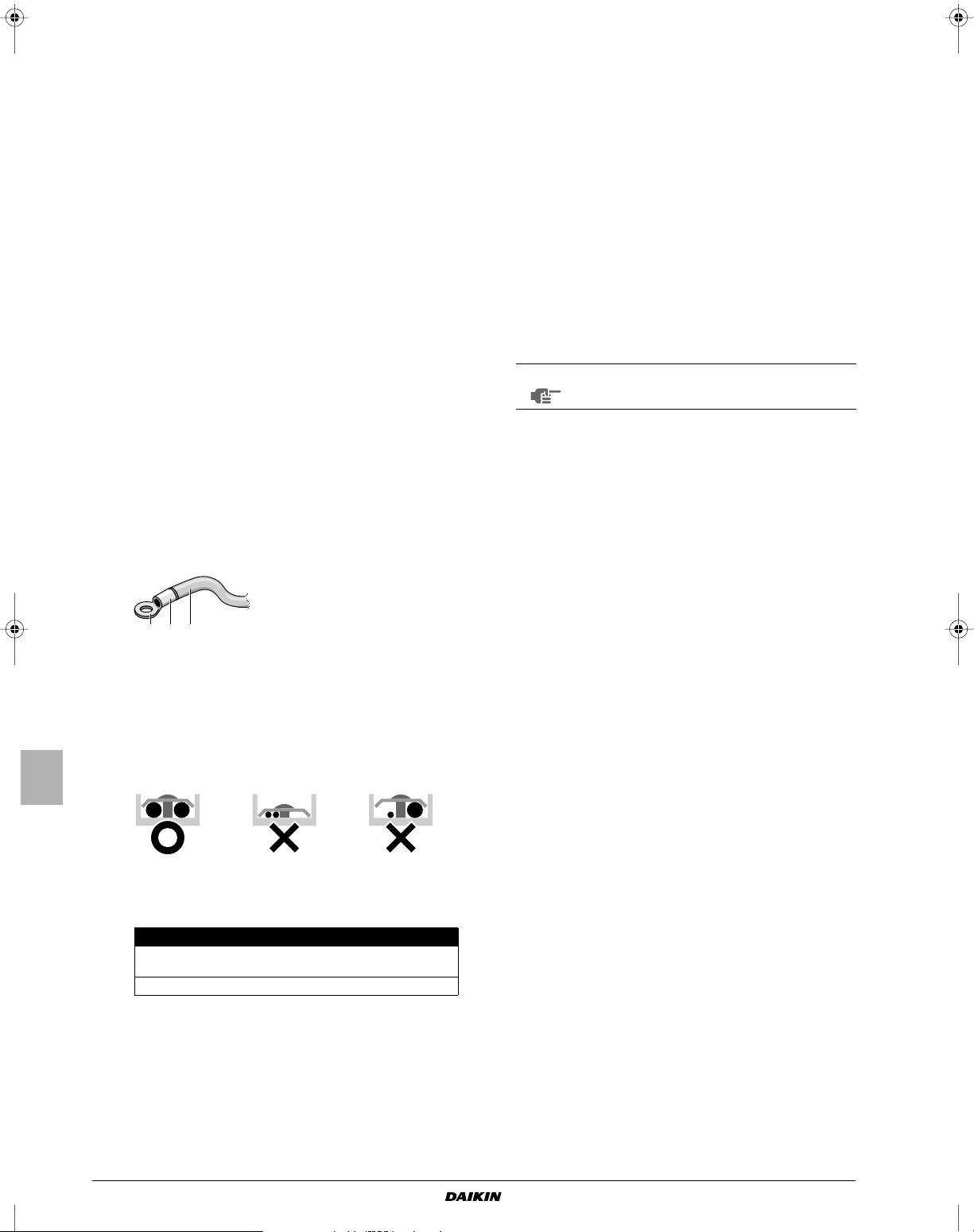
VOORBEELD VAN BEDRADING EN INSTELLEN
1 2 3
1 Ronde krimpklem
VAN DE AFSTANDSBEDIENING
Aansluiten van de bedrading (Zie afbeelding 10)
■ Voedingsbedrading
Verwijder het deksel van de besturingskast (1) en sluit de
draden aan op de klemmenstrook van de voeding erin (L, N) en
sluit de aardingskabel aan op de aardingsaansluiting. Trek
daarbij de draden naar binnen door de opening in de behuizing
en klem de draden vast met de andere draden met behulp van
een klem zoals afgebeeld.
■ Tr ansmissiebedrading van de unit en bedrading van de
afstandsbediening
Verwijder het deksel van de besturingskast (1) en trek de draden
naar binnen door de opening in de behuizing en sluit ze aan op
de klemmenstrook voor de transmissiebedrading van de unit
(F1, F2) en de bedrading van de afstandsbediening (P1, P2).
Maak de bedrading goed vast met een klem zoals afgebeeld.
■ Na het aansluiten
Bevestig de kleine (bij de unit geleverde) afdichting rondom de
kabels om te voorkomen dat van buiten af water in de unit
terecht kan komen. Als twee of meer kabels nodig zijn, deel dan
de kleine afdichting in het vereiste aantal stukken.
■ Maak het deksel van de besturingskast vast.
Voorzorgsmaatregelen
1 Neem de volgende opmerkingen in acht bij het bedraden naar
de voedingsklemmenstrook.
- Gebruik een ronde krimpaansluiting als isolatiekous voor
aansluiting op het klemmenblok voor de bedrading van de
units. Volg de onderstaande instructies als deze niet
beschikbaar zijn.
2 De totale stroom van de dwarsbedrading tussen binnenunits
moet minder dan 12 A bedragen. Tak de leiding buiten de
klemmenstrook van de unit af in overeenstemming met de
normen voor elektrische uitrustingen bij gebruik van een
dubbele voedingskabel met een dikte van meer dan dan 2 mm
(Ø1,6).
De aftakking moet zodanig worden beschermd dat die minstens
even goed is geïsoleerd als de voedingskabel zelf.
3 Sluit geen draden met een verschillende gauge aan op dezelfde
aardklem. Losse aansluitingen kunnen de bescherming
aantasten.
4 De bedrading van de afstandsbediening en transmissie van de
unit moet op minstens 50 mm van de bedrading van de voeding
liggen. Anders kan er een storing optreden als gevolg van
elektrische interferentie.
5 Raadpleeg de "Montagehandleiding van de afstandsbediening"
die is meegeleverd met de afstandsbediening voor het bedraden
van de afstandsbediening.
LET OP
De klant kan de thermistor van de afstandsbediening selecteren.
6 Sluit de voedingskabel nooit aan op de klemmenstrook voor
transmissiebedrading. Dit kan het hele systeem beschadigen.
7 Gebruik uitsluitend gespecificeerde draden en sluit die stevig
aan op de klemmen. Let op dat de draden geen externe druk
uitoefenen op de klemmen. De draden moeten zich ook in de
juiste volgorde bevinden zodat ze geen andere uitrusting
belemmeren zoals het openduwen van het servicedeurtje. Zorg
ervoor dat het deksel stevig sluit. Slecht uitgevoerde aansluitingen kunnen oververhitting veroorzaken of, in het slechtste
geval, kortsluiting of brand.
2
2 Bevestig isolatiekous
3 Bedrading
- Sluit geen draden van een verschillende gauge aan op
dezelfde voedingsklem. (Losse draden kunnen oververhitting
veroorzaken.)
- Maak de bedrading vast met de klemmen (geleverd bij de
unit) om externe druk op de bedradingsaansluitingen te
voorkomen. Maak stevig vast. Voer de bedrading netjes uit
zodat de besturingskast goed kan worden gesloten. Sluit het
deksel goed.
- Sluit draden met dezelfde dikte als volgt aan.
Gebruik de voorgeschreven elektrische draad. Bevestig de draad
stevig op de aansluitingen. Klem de draad vast zonder te grote
kracht op de aansluiting uit te oefenen. Zie de tabel hieronder
voor de aanhaalkoppels.
Aanhaalkoppel (N•m)
Klemmenstrook voor transmissie van de unit
en afstandsbediening
Klemmenstrook voor voeding 1,18~1,44
0,79~0,97
- Let erop dat er geen draden tussen het deksel en de
besturingskast worden gekneld.
-Vul nadat de bedrading aangesloten is eventuele gaten in de
bedradingsopeningen in de behuizing met stopverf of
isolatiemateriaal (lokaal te voorzien) om te voorkomen dat
kleine dieren of vuil in de unit terechtkomen en een
kortsluiting veroorzaken in de besturingskast.
Montagehandleiding en gebruiksaanwijzing
7
FMCQ50~125A7VEB
Airconditioningsysteem
4PW479629-1
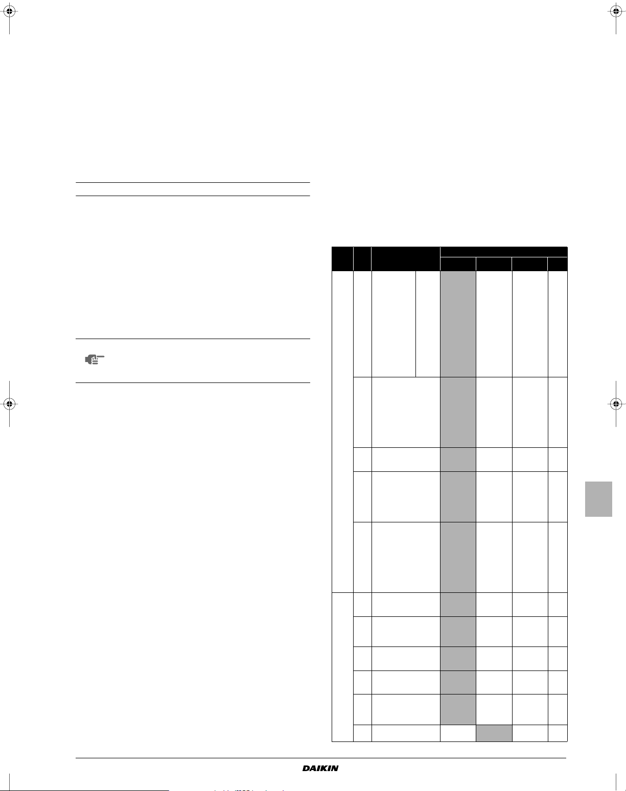
VOORBEELD VAN BEDRADING
INSTALLATIE VAN HET SIERPANEEL
Voorzie op de voedingskabel van elke unit een schakelaar en
zekering, zoals te zien op afbeelding 14.
1 Voeding
2 Hoofdschakelaar
3 Voedingsbedrading
4 Tr ansmissiebedrading unit
5 Schakelaar
6 Zekering
7 Binnenunit
8 Afstandsbediening
Voorbeeld van een compleet systeem (2 systemen)
Zie afbeelding 13 en 15.
1 Buitenunit
2 Binnenunit
3 Afstandsbediening (Optie)
4 Meest stroomafwaarts gelegen binnenunit
5 Bij gebruik van 2 afstandsbedieningen
Bij gebruik van 1 afstandsbediening voor 1 binnenunit. (Normale
werking.) (Zie afbeelding 13).
Bij groepsbesturing of gebruik van 2 afstandsbedieningen
afbeelding 15).
LET OP
Bij groepsbesturing is het niet nodig om een adres van
een binnenunit aan te duiden. Het adres wordt
automatisch ingesteld bij het inschakelen van de
voeding.
Voorzorgsmaatregelen
1. Met een enkele schakelaar kunt u de units van hetzelfde
systeem voeden. De schakelaars en werkschakelaars van de
aftakkingen moeten echter zorgvuldig worden geselecteerd.
2. Kies bij groepsbesturing met afstandsbediening een afstands-
bediening die aangepast is aan de binnenunit met de meeste
functies.
3. Aard de uitrusting niet op gasleidingen, waterleidingen en
bliksemafleiders, en voer geen dwarsaarding uit met een
telefoon. Een verkeerd uitgevoerde aarding kan kortsluiting
veroorzaken.
(Zie
Raadpleeg de montagehandleiding die bij het sierpaneel is geleverd.
Na montage van het sierpaneel moet u ervoor zorgen dat er geen
speling is tussen de unit en het sierpaneel. Anders kan er lucht door
het gat lekken waardoor condens kan worden gevormd.
LOKALE INSTELLING
Voer de lokale instelling uit met behulp van de afstandsbediening
overeenkomstig de montagecondities.
■ De instelling kan gebeuren door het "Modusnummer", "Eerste
codenr." en "Tweede codenr." te veranderen.
■ Raadpleeg het hoofdstuk "Lokale instelling" in de montagehandleiding van de afstandsbediening voor de instelling en
werking.
Samenvatting van lokale instellingen
Modusnr.
(Opmer-
king 1)
10
(20)
12
(22)
Eerste
code-
nr.
0
2
3
5
6
0
1
2
3
4
5
Beschrijving
van de instelling
Filtervervuiling Ernstig/Licht
= Instelling voor
de tijd tussen
2 aanduidingen
van filterreiniging.
(Wanneer het filter
sterk vervuild is, kan
de ingestelde tijd
tussen 2
aanduidingen van
filterreiniging
worden gehalveerd.)
Selectie thermostaatsensor
Instelling voor weergave van de
tijd tussen 2 aanduidingen van
filterreiniging
Informatie naar I-manager,
I-touch controller
Thermostaatsensor in
groepbesturing
Outputsignaal X1-X2 van de
optionele KRP1B-printplaatkit
Externe ON/OFF-input
(T1/T2-input) = Instelling als de
geforceerde AAN/UIT-instelling
extern moet gebeuren.
Omschakeling thermostaatdifferentieel = Instelling wanneer
afstandssensor wordt gebruikt.
Ventilatorinstelling wanneer
thermostaat UIT tijdens
verwarming
Differentieel automatische
omschakeling
Automatisch herstarten
na stroomonderbreking
Filter met
lange
levensduur
Tweede codenr. (Opmerking 2)
01 02 03 04
±2.500 uur
Licht
Gebruik zowel
de sensor van
de unit (of de
afstandssensor,
indien voorzien)
EN de afstandsbedieningssensor.
(Zie opmerking
5+6)
Verschijnt Verschijnt niet — —
Alleen de
waarde van de
sensor van de
unit (of de
waarde van de
afstandssensor,
indien voorzien).
Gebruik alleen
de sensor van
de unit (of de
afstandssensor,
indien voorzien).
(Zie
opmerking 6)
Thermostaat-aan
+ compressor
draait
Geforceerd UIT
1°C 0,5°C — —
LL
0°C 1°C 2°C
Uit
±1.250 uur — —
Zwaar
Gebruik alleen
de sensor van
de unit (of de
afstandssensor,
indien voorzien).
(Zie opmerking
5+6)
Waarde van de
sensor zoals
ingesteld
volgens 10-2-0X
of 10-6-0X.
Gebruik zowel
de sensor van
de unit (of de
afstandssensor,
indien voorzien)
EN de afstandsbedieningssensor.
(Zie opmerking
4+5+6)
—Werking Storing
AAN/UITwerking
Ingestelde
snelheid
Aan — —
Gebruik alleen
de afstandsbedieningssensor.
(Zie opmerking
5+6)
——
——
——
UIT (Zie
opmerking 3)
—
—
3°C
(Zie
opmerking 7)
FMCQ50~125A7VEB
Airconditioningsysteem
4PW479629-1
Montagehandleiding en gebruiksaanwijzing
8

Modusnr.
Eerste
(Opmer-
code-
king 1)
nr.
0
13
1
(23)
4
Opmerking 1 : De instelling wordt uitgevoerd in de groepmodus, maar als u het modusnummer tussen haakjes
Opmerking 2 : De fabrieksinstellingen van het Tweede codenr. staan op een grijze achtergrond.
Opmerking 3 : Gebruik alleen in combinatie met de optionele afstandssensor of wanneer de instelling 10-2-03
Opmerking 4 : Als groepbesturing is geselecteerd en de afstandsbedieningssensor moet worden gebruikt, moet
Opmerking 5 : Als instelling 10-6-02 + 10-2-01 of 10-2-02 of 10-2-03 tegelijk worden ingesteld, dan heeft
Opmerking 6 : Als instelling 10-6-01 + 10-2-01 of 10-2-02 of 10-2-03 tegelijk worden ingesteld, dan heeft bij de
Opmerking 7 : Meer instellingen voor differentieel automatische omschakeling op temperatuur:
Beschrijving
van de instelling
Instelling voor snelheid luchtuitblaas
Deze instelling
moet worden
aangepast aan de
plafondhoogte.
Selectie voor luchtstroomrichting
Deze instelling moet worden
veranderd wanneer de optionele
blokkeerkussenkit wordt
gebruikt.
Instelling bereik
luchtstroomrichting
Deze instelling moet worden
veranderd wanneer het bereik
waarbinnen de draaiklep
beweegt moet worden
veranderd.
selecteert, kunt u de binnenunits ook afzonderlijk instellen.
wordt gebruikt.
u 10-6-02 & 10-2-03 instellen.
instelling 10-2-01, 10-2-02 of 10-2-03 voorrang.
instelling voor groepaansluiting, 10-6-01 voorrang en voor individuele aansluiting heeft 10-2-01,
10-2-02 of 10-2-03 voorrang.
Tweede codenr. 05 4°C
andere
modellen
alleen
FMCQ125
06 5°C
07 6°C
08 7°C
Tweede codenr. (Opmerking 2)
01 02 03 04
≤2,7 m >2,7 ≤3,0 m >3,0 ≤3,5 m —
≤3,2 m >3,2 ≤3,6 m >3,6 ≤4,2 m —
4-wegsstroom 3-wegsstroom 2-wegsstroom —
Bovenste Midden
Onderste —
Computerbesturing (geforceerde uit en aan/uit
werking)
1. Draadspecificaties en uitvoeren van de bedrading
Draadspecificatie Beschermde vinylkoord of kabel (tweedradig)
2. Activering
Input "uit" maakt besturing mogelijk
3. Selecteren van geforceerde uit en aan/uit werking
Bij gebruik van draadloze afstandsbedieningen is het nodig om de
adresinstelling te gebruiken. Raadpleeg de montagehandleiding
meegeleverd met de draadloze afstandsbediening voor de
instructies.
Besturing met 2 afstandsbedieningen
(2 afstandsbedieningen besturen 1 binnenunit)
Bij gebruik van 2 afstandsbedieningen moet er een worden ingesteld
op "MAIN" (hoofdafstandsbediening) en de andere op "SUB"
(ondergeschikte afstandsbediening).
Omschakeling hoofd/sub
1. Steek een platte schroevedraaier in de uitsparing tussen het
bovenste en onderste gedeelte van de afstandsbediening en
verwijder vanuit de 2 posities het bovenste gedeelte. (Zie
afbeelding 18)
(De printplaat van de afstandsbediening is bevestigd op het
bovenste gedeelte van de afstandsbediening)
2. Stel de hoofd/sub-omschakelaar op een van de twee printplaten
van de afstandsbedieningen in op "S". (Zie afbeelding 19)
(Laat de schakelaar van de andere afstandsbediening ingesteld
op "M").
1 Printplaat van afstandsbediening
2 Fabrieksinstelling
3 Slechts één afstandsbediening moet worden vervangen
Centrale besturing
Bij centrale besturing is het noodzakelijk om het groepsnr. aan te
duiden. Raadpleeg voor nadere details de handleiding van elke als
optie verkrijgbare besturing voor centrale besturing.
TESTWERKING
Raadpleeg de montagehandleiding van de buitenunit.
LET OP
Het werkingslampje van de afstandsbediening knippert als er zich
een storing voordoet. Controleer de storingscode op het lcd-scherm
om de aard van de storing te bepalen. Zie de bij de buitenunit
geleverde montagehandleiding of neem contact op met uw dealer.
Zie afbeelding 21.
• Sluit de externe input aan op de klemmen T1 en T2 van de
klemmenstrook (afstandsbediening naar transmissiebedrading).
Gauge
Lengte Max. 100 m
Externe klem
Contact dat de minimale belasting van 15 V DC, 1 mA
0,75-1,25 mm
kan verzekeren
2
Zie afbeelding 17.
1 Input A
• De volgende tabel licht de werkingen "geforceerd uit" en "aan/uit"
toe bij input A.
Geforceerd uit aan/uit werking
Input "aan" stopt de werking
input uit ➜ aan: schakelt de unit in
(onmogelijk met
afstandsbedieningen)
input aan ➜ uit: schakelt de unit uit
(met de afstandsbediening)
• Schakel de voeding in en selecteer de werking met de
afstandsbediening.
• Stel de afstandsbediening in op lokale instelling. Raadpleeg voor
nadere details het hoofdstuk "Lokale instelling" in de handleiding
van de afstandsbediening.
• Selecteer bij lokale instelling werkingsnr. 12 en stel vervolgens
het eerste codenr. in op "1". Stel dan het tweede codenr. (positie)
in op "01" voor geforceerde uit werking of op "02" voor
geforceerde aan/uit werking. (De fabrieksinstelling is geforceerd
uit.) (Zie afbeelding 16)
1 Tw eede codenr.
2 Modusnr.
3 Eerste codenr.
4 Lokale instelling
Raak de afvoerpomp niet aan wanneer u lokale
instellingen uitvoert of tijdens de testwerking wanneer
het sierpaneel niet is aangebracht. Dit kan een
elektrische schok veroorzaken.
Montagehandleiding en gebruiksaanwijzing
9
1 Afvoerpomp (ingebouwd) tijdens het koelen wordt afvoerwater
verwijderd uit de kamer
2 Luchtstroomklep (aan luchtuitlaat)
3 Luchtuitlaat
4 Afstandsbediening
5 Aanzuigrooster
6 Luchtfilter (in het aanzuigrooster)
FMCQ50~125A7VEB
Airconditioningsysteem
4PW479629-1

ONDERHOUD
VOORZICHTIG
■ Het onderhoud mag alleen worden uitgevoerd door bevoegd
servicepersoneel.
■ Alle voedingscircuits moeten zijn onderbroken voordat u aan de
klemmen begint te werken.
■ Wanneer u de airconditioner wilt schoonmaken, moet u hem
eerst stilleggen en de voedingsschakelaar uitschakelen.
Anders dreigt u elektrische schokken en letsel op te lopen.
■ Was de airconditioner niet met water.
Dit kan een elektrische schok veroorzaken.
■ Wees voorzichtig met stellingen.
Ga voorzichtig te werk wanneer u op een hoogte werkt.
■ Controleer na langdurig gebruik of de stander en fitting niet
beschadigd zijn. Als deze beschadigd zijn, kan de unit vallen en
letsel veroorzaken.
■ Raak de lamellen van de warmtewisselaar niet aan.
Deze lamellen zijn scherp en kunnen snijwonden veroorzaken.
■ Vergeet voor het schoonmaken van de warmtewisselaar niet de
besturingskast, ventilatormotor, afvoerpomp en debietschakelaar te verwijderen. De isolatie van de elektronische
componenten kan door water of schoonmaakmiddel worden
aangetast, waardoor deze componenten kunnen doorbranden.
Schoonmaken van het luchtfilter
Reinig het luchtfilter als " " (REINIGINGSTIJD VOOR HET
LUCHTFILTER) op het scherm verschijnt.
Reinig het luchtfilter vaker als de unit is gemonteerd in een ruimte
waar de lucht sterk vervuild is.
(Reinig het luchtfilter in principe om de zes maanden).
Vervang het luchtfilter als het vuil niet meer te verwijderen is.
(Vervangfilters zijn als optie verkrijgbaar).
LET OP
1 Open het aanzuigrooster (Zie afbeelding 20) (handeling 1 op de
2 Verwijder het luchtfilter (handeling 2 tot 4 op de afbeelding).
3 Maak het luchtfilter schoon. (Zie afbeelding 22)
4 Schud het water af en laat het rooster drogen in de schaduw.
5 Installeer het luchtfilter weer (voer handeling 2 tot 4 op de
6 Sluit het aanzuigrooster door stap 1 in omgekeerde volgorde uit
Was het luchtfilter niet met warm water van meer dan
50°C. Anders kan het verkleuren en/of vervormd
worden.
Stel de unit niet bloot aan vuur. Anders kan er brand
ontstaan.
afbeelding).
Duw beide knoppen tegelijk in de richting van de pijl zoals
aangegeven op de afbeelding en laat het rooster voorzichtig
zakken. (Druk bij het sluiten ook op beide knoppen.)
Trek de clip van het luchtfilter aan de linker en rechter onderkant
van het filter naar u toe en maak het filter los.
Gebruik een stofzuiger of was het luchtfilter uit met water.
Gebruik een zachte borstel en een neutraal schoonmaakmiddel
als het luchtfilter sterk verontreinigd is.
afbeelding uit in omgekeerde volgorde).
Bevestig het luchtfilter op het aanzuigrooster door het op het
uitstekende gedeelte boven het aanzuigrooster te hangen.
Druk de onderkant van het luchtfilter tegen de uitstekende aan
de onderkant van het rooster om het filter in juiste positie te
plaatsen.
te voeren.
7 Druk na het inschakelen van de voeding de TERUGSTELTOETS
VOOR FILTERREINIGING in.
Het display "TIJD OM LUCHTFILTER TE REINIGEN" verdwijnt.
LET OP
Verwijder het luchtfilter niet, tenzij om het te reinigen.
Onnodige behandeling kan het luchtfilter beschadigen.
Reinigen van het aanzuigrooster
(Zie afbeelding 23)
1 Open het aanzuigrooster (handeling 1 op de afbeelding).
Zie stap 1 in "Schoonmaken van het luchtfilter" op pagina 10.
2 Maak het aanzuigrooster los
(handeling 5 tot 6 op de afbeelding).
Maak eerste de 2 linten los van de pennen van het sierpaneel.
Houd het aanzuigrooster open in een hoek van 45 graden en hef
het omhoog om het los te haken van het sierpaneel.
3 Verwijder het luchtfilter (handeling 2 tot 4 op de afbeelding).
Zie stap 2 in "Schoonmaken van het luchtfilter" op pagina 10.
4 Reinig het aanzuigrooster.
Was het met een zachte borstel en neutraal reinigingsmiddel of
water en laat het grondig drogen. Zie afbeelding 23.
LET OP
Als het aanzuigrooster erg vuil is, breng dan
gedurende een tiental minuten een typische keukenreiniger aan op het rooster. Was het vervolgens met
water.
Was het aanzuigfilter niet met warm water van meer
dan 50°C. Anders kan het verkleuren en/of vervormd
worden.
5 Installeer het luchtfilter weer (voer handeling 2 tot 4 op de
afbeelding uit in omgekeerde volgorde).
6 Monteer het aanzuigrooster weer door stap 2 in omgekeerde
volgorde uit te voeren (voer handeling 5 tot 6 op de afbeelding
uit in omgekeerde volgorde).
7 Sluit het aanzuigrooster door stap 1 in omgekeerde volgorde uit
te voeren.
Schoonmaken van de luchtuitblaas en de buitenpanelen
■ Reinig ze met een zachte doek.
■ Als sommige vlekken moeilijk te verwijderen zijn, gebruik dan
water of een neutraal schoonmaakmiddel.
LET OP
Gebruik geen benzine, benzeen, verdunner, schuurpoeder of vloeibaar insecticide. Deze producten
kunnen de onderdelen verkleuren of vervormen.
Zorg ervoor dat de binnenunit niet nat raakt. Zo niet
kan dit een elektrische schok of een brand
veroorzaken.
Schrob niet te hard wanneer u de lamellen wast met
water. De coating kan er anders afkomen.
Gebruik geen water of lucht van 50°C of meer om de
luchtfilters en buitenpanelen schoon te maken.
EISEN BIJ HET ONTMANTELEN
Het ontmantelen van de unit, behandelen van het koelmiddel, olie en
andere onderdelen moet gebeuren in overeenstemming met de
relevante lokale en nationale wetgeving.
FMCQ50~125A7VEB
Airconditioningsysteem
4PW479629-1
Montagehandleiding en gebruiksaanwijzing
10

BEDRADINGSSCHEMA
Binnenunit
A1P,A2P ..............Printplaat
C1........................ Condensator
F1U .....................Zekering (T, 5 A, 250 V)
HAP..................... Lichtgevende diode (servicecontrole - groen)
KPR..................... Magnetisch relais (afvoerpomp)
L1 ........................Spoel
M1F ..................... Motor (binnenventilator)
M1P..................... Motor (afvoerpomp)
M1S..................... Motor (draaiklep)
PS .......................Voedingscircuit
Q1DI.................... Aardsluitingsaanwijzer
R1T .....................Thermistor (lucht)
R2T .....................Thermistor (batterij)
R3T .....................Thermistor (verdeler)
S1L...................... Debietschakelaar
X1M,X2M ............Klemmenstrook
Y1E .....................Elektronische expansieklep
Afstandsbediening met kabel
R1T......................Thermistor (lucht)
SS1......................Keuzeschakelaar (HOOFD/SUB)
Ontvanger/display (gekoppeld aan draadloze
afstandsbediening)
A3P,A4P...............Printplaat
BS1......................AAN/UIT-toets
H1P......................Lichtgevende diode (Aan - Rood)
H2P......................Lichtgevende diode (Timer - Groen)
H3P......................Lichtgevende diode (Filterteken - Rood)
H4P......................Lichtgevende diode (Ontdooien - Oranje)
SS1......................Keuzeschakelaar (HOOFD/SUB)
SS2......................Keuzeschakelaar (draadloos adres-set)
Connector voor onderdelen in optie
X24A....................Connector (draadloze afstandsbediening)
X33A....................Connector (adapter voor bekabeling)
X35A....................Connector (adapter groepsregeling)
X38A....................Connector (multi tenant)
Z1C .....................Ferrietkern
Opmerkingen
1
2 Wanneer u een centrale afstandsbediening gebruikt, moet u deze aansluiten op de unit zoals beschreven in de bijgeleverde montagehandleiding.
3 X24A, X33A en X35A zijn aangesloten wanneer de accessoires in optie worden gebruikt.
4 Wanneer de externe inputdraden worden aangesloten, kan GEDWONGEN UIT of AAN/UIT BEDIENING met de afstandsbediening worden ingesteld. Zie de
montagehandleiding voor meer informatie
5 Controleer de methode voor het instellen van de keuzeschakelaar (SS1, SS2) in de montagehandleiding en technische data, enz.
6 Kleurlegende
BLK : Zwart BLU : Blauw ORG : Oranje YLW : Geel
PNK : Roze RED : Rood WHT : Wit GRN : Groen
BRN : Bruin GRY : Grijs
: Aansluitklem : Connector : Lokale bedrading
Control box : Besturingskast
Receiver/display unit : Ontvanger/display-unit
Central remote controller : Ontvanger/display-unit
Wired remote controller : Afstandsbediening met kabel
Input from outside : Externe input
Montagehandleiding en gebruiksaanwijzing
11
FMCQ50~125A7VEB
Airconditioningsysteem
4PW479629-1

FMCQ50A7VEB FMCQ100A7VEB
123 546
78 9 111210 13
1x 1x 8x 4x 1x 1x
1x 1x 1x 1x1x1x
1x
1x
14
FMCQ60A7VEB FMCQ125A7VEB
FMCQ71A7VEB
Sistema de aire acondicionado
Manual de instalación
y operación
CONTENIDOS Página
Antes de la instalación.......................................................................1
Información importante en relación al refrigerante utilizado.............. 2
Selección de la ubicación de la instalación .......................................2
Preparaciones antes de la instalación............................................... 3
Instalación de unidad para interior ....................................................3
Instalación de los tubos de refrigerante.............................................4
Tr abajo en la tubería de drenaje........................................................ 5
Ejecución del cableado eléctrico .......................................................6
Ejemplo de cableado y cómo ajustar el mando a distancia...............7
Ejemplo de cableado......................................................................... 8
Instalación del panel decorativo ........................................................8
Configuración de obra .......................................................................8
Prueba de funcionamiento...............................................................10
Mantenimiento................................................................................. 10
Requisitos relativos al desecho de residuos ...................................11
Diagrama del cableado....................................................................12
LEA ESTAS INSTRUCCIONES ATENTAMENTE ANTES
DE LA INSTALACIÓN. MANTENGA ESTE MANUAL A
MANO PARA FUTURAS CONSULTAS.
LA INSTALACIÓN O COLOCACIÓN INADECUADA DEL
EQUIPO O ACCESORIOS PODRÍA CAUSAR ELECTROCUCIÓN, CORTOCIRCUITO, FUGAS, INCENDIO U
OTROS DAÑOS AL EQUIPO. ASEGÚRESE DE
UTILIZAR SÓLO ACCESORIOS FABRICADOS POR
DAIKIN QUE SE HAN DISEÑADO ESPECÍFICAMENTE
PARA USARSE CON EL EQUIPO, Y HAGA QUE LOS
INSTALE UN PROFESIONAL.
SI NO ESTÁ SEGURO DE LOS PROCEDIMIENTOS DE
INSTALACIÓN O UTILIZACIÓN, PÓNGASE EN
CONTACTO CON EL DISTRIBUIDOR DE DAIKIN PARA
PEDIR ASESORAMIENTO E INFORMACIÓN.
ANTES DE LA INSTALACIÓN
■ Deje la unidad dentro del embalaje hasta que llegue a la ubicación de instalación. Donde no se pueda evitar el desembalaje,
utilice una eslinga de material suave o placas de protección
junto con una cuerda al levantar para evitar dañar o arañar la
unidad.
■ Consulte el manual de instalación de la unidad exterior para los
elementos que no se describen en este manual.
■ Precauciones relativas a las series de refrigerantes R410A:
Las unidades externas conectables deben estar diseñadas
exclusivamente para R410A.
■ No coloque ningún objeto demasiado cerca de la unidad
exterior ni permita que se acumulen hojas o suciedad en ella.
Las hojas constituyen el hábitat de pequeños animales que
podrían entrar en la unidad. Una vez en el interior, estos
animales pueden provocar averías, humo o fuego si entran en
contacto con los componentes eléctricos.
Precauciones
■ No instale ni haga funcionar la unidad en ambientes como los
descritos a continuación.
• Lugares con aceite mineral, o llenos de vapores de aceite o
sprays como una cocina. (las piezas de plástico se pueden
deteriorar).
• Donde exista gas corrosivo como el gas sulfuroso. (Las tuberías
de cobre y los puntos de soldadura se pueden corroer).
• Donde se utilice gas inflamable como disolvente o gasolina.
• Donde haya máquinas que generen ondas electromagnéticas.
(El sistema de control puede funcionar mal).
• Donde el aire contenga niveles altos de sal, como cerca del
océano y donde el voltaje fluctúe mucho (por ejemplo, en
fábricas). También en vehículos y naves.
■ Al seleccionar el lugar de instalación, utilice la plantilla de papel
que se proporciona para realizar dicha instalación.
■ No instale los accesorios directamente en la envoltura. El
taladrar agujeros en la envoltura puede dañar a los cables
eléctricos y por tanto causar un fuego.
Accesorios
Compruebe si se han incluido con la unidad los siguientes
accesorios.
1 Abrazadera de metal
2 Manguera de drenaje
3 Arandela para el soporte del cojinete
4 To r nillo
5 Guía de instalación
6 Manual de instalación y funcionamiento
7 Aislante para el ajuste de la tubería de gas
8 Aislante para el ajuste de la tubería de líquido
9 Almohadilla de sellado grande
10 Almohadilla de sellado medio 1
11 Almohadilla de sellado medio 2
12 Almohadilla de sellado pequeña
13 Almohadilla de sellado de drenaje
14 Plantilla de papel para la instalación (parte superior del embalaje)
Accesorios opcionales
■ Hay dos tipos de control remoto: cableado e inalámbrico.
Seleccione un control remoto de acuerdo con lo que solicite el
cliente, e instálelo en el lugar adecuado.
Consulte los catálogos y los libros técnicos para seleccionar un
control remoto adecuado.
■ Esta unidad interior requiere la instalación de un panel
decorativo opcional.
FMCQ50~125P7VEB
Sistema de aire acondicionado
4PW47629-1
Manual de instalación y operación
1

En los siguientes elementos, ponga un cuidado especial
durante la construcción, y ponga una marca de
verificación una vez finalizada la instalación
Marque ✓
cuando estén
comprobados
¿Está instalada firmemente la unidad para interiores?
■
■
■
■
■
■
■
■
■
■
La unidad puede caer, vibrar o hacer ruido.
¿Ha terminado la comprobación de fugas de gas?
Puede dar como resultado un enfriamiento o calentamiento
insuficiente.
¿Está la unidad totalmente aislada?
El agua condensada puede que gotee.
¿Fluye si problemas el drenaje?
El agua condensada puede que gotee.
¿Se corresponde el voltaje de la fuente de alimentación con el
mostrado en la placa de nombre?
La unidad puede funcionar mal o quemarse sus componentes.
¿Están instalados correctamente el cableado y los tubos?
La unidad puede funcionar mal o quemarse sus componentes.
¿Está conectada a tierra de forma segura la unidad?
Peligro en caso de fuga eléctrica.
¿Está el tamaño del cableado acorde con las especificaciones?
La unidad puede funcionar mal o quemarse sus componentes.
¿No hay nada que bloquee ni la entrada ni la salida de las
unidades de interior y de exterior?
Puede dar como resultado un enfriamiento o calentamiento
insuficiente.
¿Están anotadas la longitud de la tubería y la carga adicional de
refrigerante?
La carga de refrigerante del sistema puede no estar clara.
Notas para el instalador
■ Lea cuidadosamente este manual para asegurar una instalación
correcta de la unidad. Asegúrese de instruir al cliente sobre
cómo hacer funcionar el sistema correctamente y de mostrarle
el manual de funcionamiento que se adjunta.
■ Explique al cliente qué sistema se ha instalado. Compruebe que
ha rellenado las especificaciones apropiadas de instalación, en
el capítulo "Qué hacer antes de la puesta en funcionamiento"
del manual de operación de la unidad exterior.
INFORMACIÓN IMPORTANTE EN RELACIÓN AL
REFRIGERANTE UTILIZADO
Este producto contiene los gases fluorados de efecto invernadora
regulados por el Protocolo de Kioto.
Tipo de refrigerante: R410A
Valor GWP
(1)
GWP = global warming potential (potencial de calentamiento
global)
Puede ser necesario realizar inspecciones periódicas para localizar
fugas de refrigerante, dependiendo de las disposiciones de la
legislación europea o local vigente. Contacte, por favor, con su
distribuidor local para obtener más información.
S
ELECCIÓN DE LA UBICACIÓN DE LA INSTALACIÓN
Cuando la temperatura del techo supera los 30°C y la humedad
relativa es del 80%, o cuando se hace circular por él aire frío, se
necesita un aislamiento adicional (mínimo de 10 mm de espesor y de
espuma de polietileno).
Para esta unidad puede seleccionar diferentes direcciones de flujo
de aire. Es necesario adquirir un kit de almohadilla de bloqueo
opcional para descargar el aire en 2 o en 3 direcciones.
1Para la instalación, elija un lugar que cumpla las siguientes
Manual de instalación y operación
(1)
: 1975
condiciones y cuente con la aprobación de su cliente.
• Donde se puede asegurar una distribución de aire óptima.
• Donde nada bloquee el paso del aire.
• Donde el agua condensada se pueda drenar correctamente.
• Donde no se note el falso techo en pendiente.
2
• Donde se pueda asegurar suficiente espacio para el
mantenimiento y reparaciones.
• Cuando no hay peligro de fugas de gas inflamable.
• Donde las unidades exteriores e interiores puedan instalarse
respetando los límites máximos permitidos para las tuberías.
(Consulte el manual de instalación de la unidad de exterior.)
• Este es un producto de clase A. En un entorno doméstico, este
producto puede causar interferencias de radio, en cuyo caso el
usuario podría verse obligado a tomar las medidas adecuadas.
• Mantenga la unidad interior, la unidad exterior, el cableado de
interconexión entre unidades y el cableado del control remoto al
menos a 1metro de distancia de televisores y radios. Esto tiene
por objeto evitar interferencias en la imagen y ruido en dichos
aparatos eléctricos.
(El ruido se puede generar dependiendo de las condiciones bajo
las que se genera la onda eléctrica, incluso manteniendo la
distancia de 1 metro).
• Cuando instale el kit de control remoto inalámbrico, la distancia
entre el control remoto inalámbrico y la unidad interior podría ser
más corta si hay luces fluorescentes accionadas eléctricamente
en la habitación. La unidad interior debe instalarse lo más lejos
posible de las luces fluorescentes.
2 Altura del techo
Esta unidad interior puede instalarse en techos de hasta 3,5 m
de altura (para 125 unidades: 4,2 m). Sin embargo, es
necesario realizar ajustes de campo mediante el control remoto
cuando la unidad se instala a una altura de más de 2,7 m (para
125 unidades: 3,2 m). Para evitar el contacto accidental, se
recomienda instalar la unidad a una altura superior a 2,5 m.
Consulte el capítulo "Configuración de obra" en la página 8 y el
manual de instalación del panel decorativo.
3 Direcciones del flujo de aire
Seleccione las direcciones de flujo de aire más idóneas para la
habitación y el lugar de instalación. (Para la descarga de aire en
2 ó 3 direcciones, es necesario realizar ajustes de campo
mediante el control remoto y cerrar la(s) salida(s) de aire.
Consulte el manual de instalación del kit de almohadilla de
bloqueo opcional y el capítulo "Configuración de obra" en la
página 8). (Consulte la figura 1: = dirección del flujo de aire)
1 Descarga de aire en todas direcciones
2 Descarga de aire en 4 direcciones
3 Descarga de aire en 3 direcciones
4 Descarga de aire en 2 direcciones
NOTA
Las direcciones de flujo de aire que aparecen en
la figura 1 sirven meramente como ejemplos.
4 Utilice pernos de suspensión para la instalación.
Compruebe que el techo es lo suficientemente resistente
para soportar el peso de la unidad de interior. Si hay riesgo,
refuerce el techo antes de instalar la unidad.
(El espaciado de la instalación viene marcado en el modelo en
papel para la instalación. Consúltelo para comprobar los puntos
que hay que reforzar.)
Espacio necesario para la instalación, véase figura 2 ( =
dirección de flujo del aire)
1 Descarga de aire
2 Entrada de aire
NOTA
Deje un espacio de 200 mm o más donde esté
marcado con *; en los laterales en los que está
cerrada la salida de aire.
Modelo H
FMCQ50+60 ≥214
FMCQ71+100 ≥256
FMCQ125 ≥298
FMCQ50~125P7VEB
Sistema de aire acondicionado
4PW47629-1

PREPARACIONES ANTES DE LA INSTALACIÓN
1. Relación entre la posición de los orificios del techo para la
unidad y la del perno de suspensión.
(Consulte figura 3)
1
Tubería de refrigerante
2
Perno de suspensión (x4)
3 Abrazadera del soporte
4 Falso techo
5 Paso del perno de suspensión
6 Unidad interior
7 Abertura de techo
8 Panel decorativo
■ Consulte la guía de instalación (suministrada con la unidad)
para ver el posicionamiento exacto de la unidad en vertical.
Siga las instrucciones cortas de la
guía de instalación en caso de
instalación normal
1 21 2
1 Parte más baja del techo
2 Cara interior de la unidad
■ Se puede realizar la instalación cuando las dimensiones de la
abertura son las siguientes.
Cuando la unidad se instala dentro del bastidor para fijar los
materiales del techo. (Consulte figura 4)
1 Dimensiones dentro del bastidor
2 Dimensión de la abertura dentro del bastidor para el techo
3 Bastidor
4 Material del techo
5 Tamaño de la abertura del techo
6 Solapamiento panel-techo
NOTA
Se puede realizar la instalación con una abertura del
techo de 910 mm (marcada mediante *). No obstante,
para conseguir un solapamiento techo-panel de
20 mm, el espacio entre el techo y la unidad debería
ser de 35 mm o inferior. Si el espacio entre el techo y
la unidad es superior a los 35 mm, acople material de
techo en el componente o vuelva a cubrir el techo.
2. Realice la abertura en el techo necesaria para la instalación
allí donde sea aplicable. (Para techos existentes).
• Consulte el modelo en papel para conocer las dimensiones de la
abertura del techo.
• Haga la abertura de techo necesaria para la instalación. Desde el
lateral de la abertura hasta la salida de la carcasa, instale la
tubería de refrigerante y de drenaje y el cableado para el control
remoto (no es necesario para el tipo inalámbrico), así como la
salida de la carcasa entre las unidades interior-exterior. Consulte
la sección de cada tubería o la de cableado.
• Una vez hecha la abertura en el techo, podría ser necesario
reforzar las vigas para mantener el nivel del techo y evitar que
vibre. Para obtener información detallada, consulte al
constructor.
FMCQ50~125P7VEB
Sistema de aire acondicionado
4PW47629-1
Siga las instrucciones largas de la
guía de instalación en caso de
instalación con kit de admisión de
aire fresco
3. Instale los pernos de suspensión. (utilice un perno de tamaño
W3/8 o M10).
Utilice anclajes para los techos existentes e insertos, anclajes u
otras piezas de obra hundidas para techos nuevos para reforzar el
techo para soportar el peso de la unidad. Ajuste el espacio libre del
techo antes de proseguir.
Para ver un ejemplo de instalación consulte la figura 5.
1 Laja del techo
2 Anclaje
3 Tuerca larga o hebilla de giro
4 Perno de suspensión
5 Falso techo
NOTA
Se proporcionan en la obra todas las piezas de arriba.
Para instalaciones distintas a la estándar, póngase en
contacto con su distribuidor.
INSTALACIÓN DE UNIDAD PARA INTERIOR
Cuando instale accesorios opcionales (a excepción del panel
decorativo), lea también el manual de instalación de dichos
accesorios. Dependiendo de las condiciones de la obra, puede que
sea más fácil instalar los accesorios opcionales antes de instalar la
unidad para interior. Sin embargo, para techos ya existentes, instale
el kit de admisión de aire fresco antes de instalar la unidad.
1. Instalación de la unidad para interior temporalmente.
• Sujete la abrazadera colgante al perno de suspensión.
Asegúrese de fijarla utilizando una tuerca y una arandela desde
los extremos superior e inferior de la abrazadera colgante.
• Fijación de la abrazadera del soporte, consulte figura 6.
1 Tuerca (proporcionada en la obra)
2 Arandela (suministrada con la unidad)
3 Abrazadera del soporte
4 Doble tuerca (suministro independiente, apretada)
2. Fije la plantilla de papel para la instalación. (Sólo para
techos nuevos).
• Esta plantilla de papel corresponde a las medidas de los orificios
del techo. Para obtener información detallada, consulte al
constructor.
• En la plantilla de papel se indica el centro de la abertura del
techo para realizar la instalación. En la carcasa de la unidad y en
la plantilla de papel se indica el centro de la unidad para
proceder a la instalación.
• Después de extraer el material de embalaje de la plantilla de papel
para la instalación, coloque esta plantilla en la unidad con los
tornillos que se suministran, tal como se muestra en la figura 8.
1 Modelo de papel para la instalación
2 Centro de la abertura del techo
3 Centro de la unidad
4 To r nillos (suministrada con la unidad)
• Ajuste la altura de la unidad hasta que se adapte conforme a la
indicación de la figura 8.
3. Ajuste la unidad en la posición correcta para la instalación
(Consulte "Preparaciones antes de la instalación" en la página 3.)
4. Compruebe si la unidad está nivelada horizointalmente.
• No instale la unidad inclinada. La unidad interior está equipada
con una bomba de drenaje y un interruptor de flotador
integrados. (Si la unidad está inclinada en contra de la dirección
del flujo de drenaje, por ejemplo, el lado de la tubería de drenaje
está elevado, el interruptor de flotador puede funcionar
incorrectamente y causar goteo de agua).
• Compruebe si la unidad está nivelada en las cuatro esquinas con
un nivel de agua o un tubo de vinilo lleno de agua como se
muestra en la figura 12.
1 Nivel del agua
2 Tubo de vinilo.
5. Extraiga la plantilla de papel para la instalación. (Sólo para
techos nuevos).
Manual de instalación y operación
3

INSTALACIÓN DE LOS TUBOS DE REFRIGERANTE
C
356
6
C
356
6
Para información relativa a los tubos de la unidad exterior, consulte el
manual de instalación entregado con dicha unidad.
Lleve a cabo las tareas de aislamiento térmico en ambos lados de
las tuberías de aspiración de gas y de las tuberías de líquidos. De no
hacerse así, es posible que se produzcan fugas de agua.
Antes de montar los tubos, compruebe qué tipo de refrigerante se
utiliza.
Toda la instalación de tubos en campo debe correr a cargo
de un técnico en climatización autorizado y cumplir con la
normativa local y nacional aplicable.
■ Utilice un cortatubos y un abocador adecuados para el
refrigerante utilizado.
■ Para prevenir que el polvo, humedad o cualquier otra materia
extraña entre en el tubo, aguijonee el final o tápelo con cinta.
■ Utilice tubería de aleación de cobre sin junturas (ISO 1337).
■ La unidad para exteriores está carga de refrigerante.
■ Para evitar fugas de agua realice el aislamiento completo de los
dos lados de la tubería de gas y de líquido. Al utilizar una bomba
de calor, la temperatura de la tubería de gas puede alcanzar
hasta aprox. 120°C. Por lo tanto, utilice un aislamiento que
posea una resistencia térmica suficiente.
■ Asegúrese de utilizar juntas una llave para tuercas y una llave
inglesa para el par cuando realice la conexión o desconexión de
las tuberías a/de la unidad.
1 Llave dinamométrica
2 Llave abierta
3 Unión de tubería
4 Tuerca abocardada
■ No introduzca ninguna otra cosa que no sea el refrigerante especificado, por ejemplo, aire, dentro del circuito de refrigerante.
■ Consulte Tabla 1 para obtener información sobre las dimensiones de los espacios de las guías de la tuerca y el par de
ajuste adecuado. (Un exceso de ajuste puede dañar la guía y
causar pérdidas).
Ta bla 1
Calibre de
la tubería
Ø6,4 14,2~17,2 N•m 8,7~9,1
Ø9,5 32,7~39,9 N•m 12,8~13,2
Ø12,7 49,5~60,3 N•m 16,2~16,6
Ø15,9 61,8~75,4 N•m 19,3~19,7
Par de ajuste
Dimensiones de la
guía A (mm)
■ Cuando conecte la tuerca abocardada, recubra el abocardado
con aceite de éter o de éster por dentro y por fuera y dé tres o
cuatro vueltas con la mano antes de apretar firmemente.
Recubra aquí con aceite de éter o de éster
12
3
4
Forma del
abocardado
±2
90°
45°
±2
A
R=0 4 0 8
■ Finalmente, realice el aislamiento como se indica en la siguiente
figura (utilice los accesorios suministrados).
4
5
3
5
1
2
1 Tubería de líquido
2 Tubería de gas
3 Aislante para el ajuste de la
tubería de líquido
4 Aislante para el ajuste de la
tubería de gas
5 Abrazaderas
(utilice 2 abrazaderas por
aislamiento)
Procedimiento de aislamiento de tuberías
Tubería de gas Tubería de líquido
1 Material aislante de tuberías (de suministro en obra)
2 Conexión de tuerca abocardada
3 Aislamiento para la fijación (suministrado con la unidad)
4 Material aislante de tuberías (unidad principal)
5 Unidad principal
6 Abrazadera (suministro independiente)
7 Almohadilla de sellado medio 1 para la tubería de gas
(suministrada con la unidad)
Almohadilla de sellado medio 2 para la tubería de gas
(suministrada con la unidad)
A Girar costuras hacia arriba
B Acoplar a la base
C Apretar la parte distinta al material de aislamiento de la
tubería
D Envolver desde la base de la unidad hasta la parte superior
de la conexión de tuerca abocardada.
En cuanto al aislamiento local, asegúrese de aislar la
tubería local por todo el largo hasta las conexiones de
tubo del interior de la unidad.
La tubería expuesta puede causar condensación o
provocar quemaduras si se toca.
Precauciones para la soldadura
■ Asegúrese de realizar un soplado con nitrógeno durante la
soldadura.
(Si se realiza la soldadura sin reemplazo de nitrógeno o
liberación de nitrógeno hacia la tubería provocará la formación
de una gran cantidad de película oxidada en el interior de las
paredes de la tubería, con un efecto perjudicial para las válvulas
y los compresores del sistema de refrigeración e impide el
funcionamiento normal del sistema.)
■ Al soldar durante la inserción de nitrógeno en el sistema de
tuberías, el nitrógeno debe estar ajustado a 0,02 MPa con una
válvula de reducción de presión (=suficiente, de forma que se
pueda sentir sobre la piel).
12 345
■ Si se produce una fuga de gas durante la instalación, ventile la
zona. Si el gas refrigerante se expone al fuego, emitirá un gas
tóxico.
■ Asegúrese de que no hay fugas de gas refrigerante. Si se
produce una fuga de gas refrigerante en la unidad interior y el
gas se ve expuesto a las llamas de una estufa o cocina, puede
emitir un gas tóxico.
Manual de instalación y operación
4
1 Tubería de refrigerante
2 Pieza de soldadura
3 Cinta protectora
4 Válvula manual
5 Válvula reductora de presión
6 Nitrógeno
6
6
FMCQ50~125P7VEB
Sistema de aire acondicionado
4PW47629-1

TRABAJO EN LA TUBERÍA DE DRENAJE
Instalación de la tubería de drenaje
Instale la tubería de drenaje como se muestra en la figura y tome las
medidas oportunas para evitar la condensación. Las tuberías
aparejadas de forma incorrecta pueden presentar fugas y mojar los
muebles y otras pertenencias.
-Envuelva la almohadilla de sellado larga suministrada
alrededor de la abrazadera de metal y la tubería de drenaje
para aislarla y fíjela mediante abrazaderas.
- Aisle la tubería de drenaje completa del interior del edificio
(de suministro independiente).
- Si no se puede dar una inclinación adecuada a la manguera
de drenaje, ajuste dicha manguera con tuberías de drenaje
ascendentes (se suministran en obra).
■ Como instalar la tubería (Consulte figura 7)
1-1.5 m
1 Barra de refuerzo
1
■ Instale los tubos de drenaje.
- Mantenga las longitudes de tubo lo más cortas posible e
inclínelas hacia abajo en una pendiente de al menos 1/100
de forma que el aire no quede atrapado en el interior de la
tubería.
- El tamaño de la tubería debe ser igual o mayor que el de la
tubería de conexión (tubería de vinilo de 25 mm de diámetro
nominal y 32 mm de diámetro exterior).
- Tire la manguera de drenaje suministrada hasta el máximo
posible por encima del cubo de drenaje.
21
1 Cubo de drenaje (adjunto a la unidad)
2 Manguera de drenaje (suministrada con la unidad)
- Apriete la abrazadera de metal hasta que la cabeza del
tornillo se encuentre a una distancia menor de 4 mm con
respecto a la abrazadera metálica, como se indica en la
ilustración.
- Después de comprobar la tubería de drenaje acople la
almohadilla de sellado (4) suministrada con la unidad sobre
la parte descubierta del cubo de drenaje (= entre la
manguera de drenaje y el cuerpo de la unidad).
4 3 5
1
A-A'
1 Laja del techo
2 Abrazadera del soporte
3 Rango ajustable
4 Tubo de elevación del drenaje (diámetro nominal del tubo de vinilo
= 25 mm)
5 Manguera de drenaje (suministrada con la unidad)
6 Componente metálico de la abrazadera (suministrado con la
unidad)
1 Conecte la manguera de drenaje a las tuberías de drenaje
ascendentes, y aíslelas.
2 Conecte la manguera de drenaje a la salida de drenaje de la
unidad exterior, y apriétela con la pinza.
■ Precauciones
- Instale las tuberías ascendentes a una altura menor de
675 mm.
- Instale estos tubos formando un ángulo recto con la unidad
interior y a no más de 300 mm de ella.
-Para impedir que se formen burbujas de aire, instale la
manguera de drenaje nivelada o ligeramente inclinada hacia
arriba (≤75 mm).
NOTA
La inclinación de la manguera de drenaje
acoplada debe ser de 75 mm o inferior para
que el manguito de drenaje no tenga que
soportar una presión adicional.
Para asegurar una inclinación hacia abajo de
1:100, instale barras de refuerzo entre cada 1
ó 1,5 m.
Si se van a unir múltiples tuberías de drenaje,
instálelas como se muestra en figura 9.
Seleccione tubos de drenaje convergentes
cuyo calibre sea adecuado para la capacidad
operativa de la unidad.
1 Tubos de drenaje convergentes con unión
en T
1 Cubo de drenaje (adjunto a la unidad)
2 Manguera de drenaje (suministrada con la unidad)
3 Abrazadera metálica (suministrada con la unidad)
4 Almohadilla de sellado (suministrada con la unidad)
5 Almohadilla de sellado grande (suministrada con la
unidad)
6 Tubería de drenaje (suministro independiente)
FMCQ50~125P7VEB
Sistema de aire acondicionado
4PW47629-1
4 mm
3
5
1
2
6
Manual de instalación y operación
5

Comprobación de la tubería de drenaje
Una vez terminada la instalación de la tubería, compruebe que el
drenaje fluye normalmente.
■ Añada aproximadamente 1 l de agua poco a poco a través de la
salida de descarga de aire.
Método para añadir agua. Consulte figura 11.
1 Lata de plástico para la carga de agua (el tubo debería tener
aprox. 100 mm de longitud)
2 Salida de drenaje de mantenimiento (con tapón de caucho)
(utilice esta salida para drenar el agua de la bandeja de
drenaje)
3 Ubicación de la bomba de drenaje
4 Tubo de drenaje
5 Cubo de drenaje (punto de vista del flujo de agua)
■ Compruebe el flujo de drenaje.
■ Una vez realizado el cableado eléctrico
Compruebe el flujo de drenaje durante en funcionamiento en
modo REFRIGERACIÓN, explicado en el capítulo "Prueba de
funcionamiento" en la página 10.
■ Si el cableado eléctrico aún no se ha realizado
- Retirar la tapa de la caja de controles. Conecte la alimentación de forma segura al terminal. Consulte figura 10.
-Vuelva a acoplar la tapa de la caja de controles y
encienda la alimentación.
- No toque la bomba de drenaje. Puede sufrir una
electrocución.
1 Tapa de la caja de controles
2 Cableado de la fuente de alimentación
3 Bloque terminal de la fuente de alimentación
4 Abrazadera (suministro independiente)
5 Cableado de interconexión entre unidades
6 Bloque de terminales para el cableado de
transmisión
7 Abertura de paso de cables
8 Etiqueta del diagrama de conexiones
(situada en la parte posterior de la tapa de la caja de
conexiones)
9 Cable de conexión a tierra
10 Cableado del control remoto
Bloque terminal del cableado entre las unidades (3)
N
L
- Asegúrese de que el drenaje se está realizando
observando el cubo de drenaje.
- Después de verificar el correcto flujo de drenaje, corte la
alimentación, extraiga la tapa de la caja de controles y
vuelva a desconectar la alimentación eléctrica del
terminal.
-Vuelva a acoplar la tapa de la caja de controles.
EJECUCIÓN DEL CABLEADO ELÉCTRICO
Instrucciones generales
■ Todas las piezas que se proporcionan en la obra y los trabajos
eléctricos tienen que ajustarse a las normas locales.
■ Use solamente hilos conductores de cobre.
■ Para la instalación del cableado de la unidad exterior, las
unidades interiores y el control remoto, observe el "diagrama de
cableado" fijado al cuerpo de la unidad. Para detalles sobre el
enganche del mando a distancia, consulte el "Manual de
instalación del mando a distancia".
■ Todo el cableado deberá ser efectuado por un electricista
autorizado.
■ Acople un diferencial de fugas a tierra y un fusible en la línea de
alimentación.
■ En el cableado fijo deberá incorporarse, según la reglamentación local y nacional pertinente, un interruptor principal u otro
medio de desconexión que tenga una separación constante en
todos los polos.
Tenga en cuenta que el aparato se pondrá en funcionamiento
automáticamente si se desconecta la fuente de alimentación
principal y se conecta de nuevo.
■ Este sistema se compone de múltiples unidades interiores.
Marque cada una de ellas como unidad A, unidad B..., y
asegúrese de que las conexiones del cuadro eléctrico a la
unidad exterior estén correctamente conectadas. Si las
conexiones eléctricas y las conducciones entre la unidad
exterior y alguna de las interiores no son correctas, puede
provocar un mal funcionamiento del sistema.
■ Asegúrese de conectar a tierra la unidad de aire acondicionado.
■ No conecte el cable de tierra a:
- tuberías de gas: puede producirse una ignición o explosión si
se producen fugas de gas.
- cables con toma de tierra en teléfonos o varas de
iluminación: el potencial eléctrico podría elevarse de forma
anormal en el suelo durante las tormentas eléctricas.
- tuberías de fontanería: no será posible un efecto de puesta a
tierra si se utiliza una tubería de vinilo duro.
Características eléctricas
Modelo Hz Voltios Rango de voltaje
FMCQ50~125 50 220-240 mín. 198-máx. 264
alimentación Motor del ventilador
Modelo MCA MFA KW FLA
FMCQ50 0,6 16 A 0,056 0,5
FMCQ60 0,9 16 A 0,056 0,7
FMCQ71 0,9 16 A 0,120 0,7
FMCQ100 1,4 16 A 0,120 1,1
FMCQ125 1,9 16 A 0,120 1,5
MCA: Amperaje mínimo del circuito (A)
MFA: Amperaje máximo del fusible (A)
KW: Salida nominal del motor del ventilador (kW)
FLA: Amperaje de carga completa (A)
NOTA
Para obtener más detalles, consulte "Datos eléctricos".
Manual de instalación y operación
6
FMCQ50~125P7VEB
Sistema de aire acondicionado
4PW47629-1

Especificaciones para los fusibles y cableado
suministrados en obra
Cableado de la fuente de alimentación
Fusibles de
Modelo
FMCQ50~125 16 A H05VV-U3G
Modelo Cable Tamaño
FMCQ50~125 Cable envainado (2)
obra
Instalación eléctrica de la transmisión
Cable Tamaño
0,75-1,25 mm
Normas
locales
- Cuando fije el cableado utilice las abrazaderas suministradas
junto con la unidad para impedir que se ejerza presión
exterior sobre las conexiones del cableado. Fíjelo con
seguridad. Cuando realice el cableado, asegúrese de que
está bien ordenado para que no obstruya otros equipos,
como por ejemplo, hacer que se abra la caja de control.
Cierre la tapa con seguridad.
- Cuando conecte cables de mismo calibre, conéctelos de
acuerdo con la figura.
2
NOTA
■ Para obtener más detalles, consulte el capítulo
"Ejemplo de cableado" en la página 8.
■ La longitud de instalación eléctrica permisible
entre las unidades interiores y exteriores, y entra
la unidad interior y el mando a distancia es la
siguiente:
• Unidad exterior - unidad interior: máx. 1000 m
(longitud total del cableado: 2000 m).
• Unidad interior – control remoto: 500 m como
máximo.
EJEMPLO DE CABLEADO Y CÓMO AJUSTAR EL
MANDO A DISTANCIA
Cómo conectar el cableado (Consulte figura 10)
■ Cableado de la fuente de alimentación
Extraiga la tapa de la caja de control (1), conecte los cables al
bloque de terminales de alimentación elétrica en el interior
(L, N) y conecte el cable de tierra al terminal de tierra. Mientras
realiza esta función, pase los cables hacia el interior a través del
orificio de la carcasa y fije los cables junto con otros cables
mediante una abrazadera, como se indica en la figura.
■ Cableado de transmisión de la unidad y del control remoto
Extraiga la tapa de la caja de controles (1) y pase los cables al
interior introduciéndolos a través del agujero de la carcasa y
conéctelos al bloque del terminales para el cableado de
transmisión de las unidades (F1, F2) y el cableado del control
remoto (P1, P2). Fije adecuadamente el cableado mediante una
abrazadera, tal y como se indica en la figura.
■ Después de conectar
Coloque el pequeño sellado que se suministra con la unidad
alrededor de los cables para evitar la infiltración de agua del
exterior de la unidad. Si se utilizan dos o más cables, divida el
sellado en el número de partes necesarias y enróllelas en los
cables.
■ Acople la tapa de la caja de control.
Precauciones
1 Observe las notas mencionadas más abajo cuando cablee la
placa del bloque de terminales de la fuente de alimentación.
- Utilice un terminal rodondo engarzado para el manguito de
aislamiento de conexión al bloque de terminales para
conectar el cableado de las unidades. Si no queda ninguno
libre, siga las siguientes instrucciones.
1 Te r minal engarzado
redondeado
1 2 3
- No conecte cables de diferente calibre al mismo terminal de
alimentación. (Si la conexión está floja, se puede provocar
sobrecalentamiento.)
2 Acople el manguito de
aislamiento
3 Cableado
Utilice el cable eléctrico especificado. Conecte el cable
firmemente al terminal. Fije el cable al terminal sin presionar
excesivamente. Utilice los pares de apriete correspondientes que
se indican en la siguiente tabla.
Par de apriete (N•m)
Bloque de terminales para la transmisión entre
unidades y el control remoto
Bloque de terminales de alimentación eléctrica 1,18~1,44
0,79~0,97
- Cuando acople la tapa de la caja de control asegúrese de no
pellizcar ningún cable.
- Después de realizar todas las conexiones del cableado,
rellene los agujeros libres para el cableado en la carcasa con
plastilina o material aislante (de suministro independiente)
para impedir que pequeños animales aniden allí o que
penetre la suciead en la unidad desde el exterior y se
produzcan cortocircuitos en la caja de control.
2 Mantenga la corriente total de cruce de cables en un valor
inferior a 12 A. Derive la línea fuera del cuadro eléctrico de la
unidad, de acuerdo con las normas relativas al equipos
eléctrico, cuando utilice dos cables de conexión de calibre
superior a 2 mm
2
(Ø1,6).
Debe forrarse la derivación para proporcionar un grado de
aislamiento igual o mayor del que tiene el propio cable.
3 No conecte cables de diferente calibre a la misma terminal de
toma de tierra. Si la conexión está floja, se puede provocar un
deterioro en la protección.
4 El cableado del control remoto y de transmisión de la unidad
debe colocarse al menos con 50 mm de separación con
respecto al cableado de alimentación. El incumplimiento de esta
directriz podría causar fallos en el funcionamiento debido a
ruido eléctrico.
5 Para el cableado del mando a distancia, consulte el "Manual de
instalación del mando a distancia" que viene con el mando a
distancia.
NOTA
El cliente puede seleccionar el termistor del
mando a distancia.
6 Nunca conecte el cableado de la fuente de alimentación al
bloque de terminales del cableado de transmisión. Tal error
podría causar averías en todo el sistema.
7 Utilice solamente los cables especificados y conecte los cables
firmemente a los terminales. Tenga cuidado de no hacer
demasiada fuerza sobre los terminales. Mantenga el cableado
en orden para que no obstruyan otros equipos, además de para
poder abrir la tapa de mantenimiento. Asegúrese de que la tapa
se cierra firmemente. Cualquier conexión deficiente podría
provocar un calentamiento excesivo y, en el peor de los casos,
descargas eléctricas o fuego.
FMCQ50~125P7VEB
Sistema de aire acondicionado
4PW47629-1
Manual de instalación y operación
7

EJEMPLO DE CABLEADO
CONFIGURACIÓN DE OBRA
Monte la instalación eléctrica de cada unidad con un interruptor y un
fusible, según se muestra en la figura 14.
1 Alimentación eléctrica
2 Interruptor principal
3 Cableado de la fuente de alimentación
4 Cableado de interconexión entre unidades
5 Interruptor
6 Fusible
7 Unidad interior
8 Control remoto
Ejemplo de sistema completo (2 sistemas)
Consulte las figuras 13 y 15.
1 Unidad exterior
2 Unidad interior
3 Control remoto (accesorios opcionales)
4 Unidad interior más abajo
5 Para utilizar con 2 controles remotos
Al utilizar 1 mando a distancia para 1 unidad interior.
(Funcionamiento normal) (Consulte figura 13).
Para control en grupo o utilización de 2 controles remotos
(Consulte figura 15).
NOTA
No es necesario designar la dirección de la unidad
interior cuando se utiliza el control de grupo. La
dirección se establece automáticamente cuando se
activa la alimentación.
Precauciones
1. Se puede utilizar un sólo interruptor para dar alimentación a las
unidades de un mismo sistema. Sin embrago, los interruptores y
los disruptores de las ramas se deben elegir cuidadosamente.
2. Para el control remoto de un control de grupo, elija el que tenga
más funciones tenga en relación con la unidad interna.
3. No conecte el equipo a tierra a través de tuberías de gas,
conductores de pararrayos u otros cables de tierra de circuitos
telefónicos. Una toma a tierra incorrecta puede tener como
resultado una descarga eléctrica.
INSTALACIÓN DEL PANEL DECORATIVO
Consulte el manual de instalación suministrado con el panel
decorativo.
Después de instalar el panel decorativo, asegúrese de que no hay
espacio entre el cuerpo de la unidad y el panel decorativo. Si no
fuera así, podría haber fugas de aire por el hueco y producirse
condensación.
El ajuste de obra se tiene que hacer desde el mando a distancia de
acuerdo con las condiciones de la instalación.
■ El ajuste puede hacerse cambiando el "Número de modo",
"Número de código primero" y "Número de código segundo".
■ Para el ajuste y operación, consulte "Configuración de obra" en
el manual de instalación del controlador remoto.
Resumen de la configuración de obra
Nº de
modo
(Nota 1)
10
(20)
12
(22)
Número
de
código
Descripción del parámetro
primero
Contaminación del
filtro - Intensa/Ligera
= Parámetro que
establece el tiempo
de funcionamiento
entre 2 indicaciones
en pantalla para la
limpieza del filtro.
0
(Cuando la
contaminación es
alta, el ajuste de
tiempo entre indicaciones en pantalla
para la limpieza del
filtro puede reducirse
a la mitad.)
Selección del sensor del
2
termostato
Parámetro para mostrar el tiempo
que ha de transcurrir entre dos
3
indicaciones en pantalla para la
limpieza del filtro.
Información al I-manager,
5
I-touch controller
Sensor del termostato en el
6
control de grupo
Señal de salida X1-X2 del kit
0
opcional KRP1B PCB
Entrada ON/OFF del exterior
(Entrada T1/T2) = Parámetro
1
para el encendido/apagado
forzado desde el exterior.
Diferencial de conmutación
del termostato = Parámetro
2
aplicable en caso de utilización
de sensor remoto.
Configuración del ventilador
para los periodos de termostato
3
en OFF durante el
funcionamiento de calefacción
Diferencial de conmutación
4
automática
Rearranque automático tras
5
un fallo de alimentación
Filtro de
vida larga
Nº de código segundo (Nota 2)
01 02 03 04
±2.500 hrs.
Ligera
Uso del sensor
de la unidad
(o el sensor
remoto si hay
uno instalado)
Y TAMBIÉN
del sensor del
controlador
remoto.
(Véase
nota 5 y 6)
Mostrar No mostrar — —
Solamente el
valor del sensor
de la unidad
(o del sensor
remoto si hay
uno instalado).
Uso del sensor
de la unidad
solamente
(o del sensor
remoto si hay
uno instalado).
(Véase nota 6)
Te rmostato
activado +
compresor
en marcha
Forzado OFF
1°C 0,5°C — —
LL
0°C 1°C 2°C
Desactivado
±1.250 hrs. — —
Intensa
Uso del sensor
de la unidad
solamente
(o del sensor
remoto si hay
uno instalado).
(Véase
nota 5 y 6)
Valor del sensor
establecido
según 10-2-0X
ó 10-6-0X.
Uso del sensor
de la unidad (o
del sensor
remoto si hay
uno instalado)
Y TAMBIÉN del
sensor del
controlador
remoto. (Véase
nota 4, 5 y 6)
— Operación
Operación
encendido/
apagado
Velocidad
establecida
Activado — —
Uso del sensor
del controlador
remoto
solamente.
(Véase
nota 5 y 6)
——
——
——
OFF (apagado)
(Véase nota 3)
—
Anomalía
—
3°C
(Véase
nota 7)
Manual de instalación y operación
8
FMCQ50~125P7VEB
Sistema de aire acondicionado
4PW47629-1

Número
Nº de
de
modo
código
(Nota 1)
13
(23)
Nota 1 : La configuración se realiza en el modo de grupo, sin embargo, si se selecciona el número que figura
Note 2 : Los ajustes de fábrica del segundo Nº de código van marcados con fondos grises.
Note 3 : Usar solamente en combinación con el sensor remoto opcional o cuando se utiliza la configuración
Note 4 : Si se selecciona control de grupo y se va a usar el sensor del controlador remoto, establezca
Note 5 : Si la configuración 10-6-02 + 10-2-01, 10-2-02 ó 10-2-03 se establecen al mismo tiempo, entonces
Note 6 : Si la configuración 10-6-01 + 10-2-01, 10-2-02 ó 10-2-03 se establecen al mismo tiempo, entonces
Nota 7 : Otros ajustes para temperaturas diferenciales de conmutación automática son:
Descripción del parámetro
primero
Ajuste de la
velocidad de salida
de aire
Este ajuste debe
0
cambiarse en
función de la altura
del techo.
Selección de la dirección del
flujo de aire
Este ajuste debe cambiarse
1
cuando se utilice un kit opcional
de bloqueo.
Ajuste del rango de orientación
del flujo de aire
Este ajuste debe cambiarse
4
cuando deba variarse el rango
del movimiento de inclinación de
la aleta deflectora.
entre paréntesis, las unidades exteriores pueden ser configuradas también individualmente.
10-2-03.
la configuración 10-6-02 y 10-2-03.
tiene prioridad la configuración 10-2-01, 10-2-02 ó 10-2-03.
tiene prioridad la configuración 10-6-01 para conexión en grupo y para conexión individual tienen
prioridad 10-2-01, 10-2-02 ó 10-2-03.
Segundo Nº de código 05 4°C
otros
modelos
Sólo en el
FMCQ125
06 5°C
07 6°C
08 7°C
Nº de código segundo (Nota 2)
01 02 03 04
≤2,7 m >2,7 ≤3,0 m >3,0 ≤3,5 m —
≤3,2 m >3,2 ≤3,6 m >3,6 ≤4,2 m —
flujo de 4 vías flujo de 3 vías flujo de 2 vías —
Alto Posición media
Bajo —
■ Cuando se utilizan controles remotos inalámbricos, hay que
utilizar el ajuste de dirección. Consulte el manual de instalación
que se incluye con estos controles para las instrucciones de
ajuste.
Control con 2 mandos a distancia (controlando
1 unidad interior con 2 mandos a distancia)
Al utilizar 2 mandos a distancia, uno se debe ajustar a "Principal" y el
otro a "SUB".
Conversión Principal/Sub
1. Inserte un destornillador de cabeza de cuña en el recoveco
entre la parte superior e inferior del mando a distancia y funcionando desde las 2 posiciones, mueva la parte superior.
(Consulte figura 18)
(La placa del mando a distancia está sujeta a la parte superior
del mando a distancia).
2. Encienda el interruptor de conversión Principal/Sub de las dos
placas de los mandos a distancia a "S". (Consulte figura 19)
(Deje el interruptor del otro mando a distancia ajustado a "M").
1 Placa del mando a distancia
2 Ajustes de fábrica
3 Sólo se necesita cambiar un control remoto
Control computerizado (funcionamiento con activado y
activado/desactivado forzados)
1. Especificaciones de la instalación eléctrica y cómo realizar esta
instalación.
• Conecte la entrada desde fuera a las terminales T1 y T2 del
bloque de terminales (mando a distancia a la instalación eléctrica
de la transmisión).
Especificaciones
del cable
Calibre
Cordón de vinilo envainado o cable (2 hilos)
0,75-1,25 mm
2
Longitud Máx. 100 m
Te r minal exterior
Un contacto que pueda asegurar la pérdida mínima
aplicable de 15 V de CC y 1 mA
Consulte figura 17.
1 Entrada A
2. Actuación
• La tabla siguiente explica los funcionamientos "sin forzar" y "con/
sin forzar" en respuesta a la entrada A.
funcionamiento activado/
Sin forzar
La entrada "on" detiene la operación
Entrada "desactivada" activa el
control
entrada desactivada ➜ activada:
entrada activada ➜ desactivada:
apaga la unidad (mediante control
desactivado
enciende la unidad (imposible
mediante control remoto)
remoto)
3. Cómo seleccionar el funcionamiento sin forzado y activado/
desactivado)
• Encienda y utilice el mando a distancia para seleccionar el
funcionamiento.
• Sitúe el mando a distancia en modo configuración de campo.
Para obtener más detalles, consulte el capítulo "Cómo poner en
movimiento el campo", en el manual del mando a distancia.
• Cuando esté en el modo de campo, seleccione el modo nº 12 y, a
continuación, sitúe el primer número de código en "1". Después,
coloque el segundo número de código (posición) en "01" para
desactivar el forzado y en "02" para funcionamiento activado/
desactivado. (La configuración de fábrica está en forzado
desactivado.) (Consulte figura 16)
1 Número de código segundo
2 Número de modo
3 Número de código primero
4 Modo de configuración personalizada
Control centralizado
Para realizar un control centralizado, es necesario designar el
número de grupo. Para obtener más detalles, consulte el manual de
cada mando opcional, para control centralizado.
FMCQ50~125P7VEB
Sistema de aire acondicionado
4PW47629-1
Manual de instalación y operación
9

PRUEBA DE FUNCIONAMIENTO
Consulte el manual de instalación de la unidad exterior.
NOTA
Cuando realice los ajustes de campo o una prueba de
funcionamiento sin colocar el panel decorativo, no
toque la bomba de drenaje. Pueden producirse descargas eléctricas.
La luz de funcionamiento del mando a distancia parpadeará cuando
se produzca un fallo. Compruebe el código de error que aparece en
la pantalla de cristal líquido, para identificar la avería. Consulte el
manual de instalación que viene con la unidad exterior o póngase en
contacto con su distribuidor. Consulte figura 21.
1 Dispositivo de bombeo del drenaje (interno). El agua de drenaje
se elimina durante la refrigeración.
2 Aleta de flujo de aire (en la salida de aire)
3 Salida de aire
4 Control remoto
5 Rejilla de aspiración
6 Filtro del aire (rejilla de aspiración interior)
MANTENIMIENTO
PRECAUCIÓN
■ Solamente un técnico cualificado puede llevar a cabo tareas de
mantenimiento.
■ Antes de acceder a los dispositivos eléctricos, deberán
desconectarse todos los circuitos de alimentación.
■ Antes de limpiar el aparato, asegúrese de detener el funcionamiento y desconectar el suministro eléctrico.
De lo contrario, pueden producirse descargas eléctricas y
lesiones.
■ No lave con agua el acondicionador de aire.
Pueden producirse descargas eléctricas.
■ Tenga precaución con los andamios.
Es necesario tener cuidado cuando se trabaja en altura.
■ Después de un uso prolongado, compruebe si la estructura de
apoyo y los elementos de fijación presentan algún daño. De lo
contrario, pueden producirse accidentes por la caída del equipo.
■ No toque las aletas del intercambiador de calor.
Son unas aletas muy afiladas y podrían causar lesiones por
corte.
■ Cuando limpie el intercambiador de calor, asegúrese de extraer
la caja de controles, el motor del ventilador, la bomba de drenaje
y el interruptor de flotador. El agua y los detergentes pueden
deteriorar el aislante de los componentes electrónicos y
provocar que se quemen.
Cómo limpiar el filtro del aire
Limpie el filtro del aire cuando la pantalla muestre " " (HORA
DE LIMPIAR EL FILTRO DEL AIRE).
Aumente la frecuencia de limpieza si la unidad está instalada en una
habitación donde el aire esté extremadamente contaminada.
(Como vara de medir, considere limpiar el filtro dos veces al año).
Si la suciedad se hace imposible de limpiar, cambie el filtro del aire.
(Filtro del aire para intercambio es opcional).
NOTA
No lave el filtro de aire con agua a más de 50°C. De
hacerlo, podría decolorarse o deformarse.
No exponga la unidad al fuego. Podría llegar a
quemarse.
1 Abra la rejilla de aspiración (Consulte figura 20)(acción 1 en la
ilustración).
Empuje las dos palancas simultáneamente en la dirección de la
flecha como se indica en la ilustración y desplace con cuidado
la rejilla hacia abajo. (procedimiento idéntico para el cierre.)
2 Desmonte el filtro de aire. (acciones 2 a 4 en la ilustración).
Tire del clip del filtro de aire hacia usted hacia lado inferior
izquierdo y derecho del filtro y desacóplelo.
3 Limpie el filtro del aire. (Consulte figura 22)
Utilice una aspiradora o lave el filtro del aire con agua.
Cuando el filtro del aire está muy sucio, utilice un cepillo suave y
detergente neutro.
4 Quite el agua y séquelo a la sombra.
5 Vuelva a colocar el filtro de aire donde le corresponde (realice
las acciones 2 a 4 en la ilustración, en orden inverso).
Acople el filtro de aire a la rejilla de aspiración colgándolo en la
parte saliente encima de la rejilla de aspiración.
Presione la parte inferior del filtro de aire contra los salientes de
la parte inferior de la rejilla para encajar el filtro en su sitio.
6 Cierre la rejilla de aspiración realizando el paso 1 en orden
inverso.
7 Después de apagar la unidad, pulse el botón FILTER SIGN
RESET.
Desaparece la indicación "HORA DE LIMPIAR EL FILTRO DE
AIRE".
NOTA
No quite el filtro de aire excepto para limpiarlo. Si se
maneja innecesariamente, se puede dañar.
Forma de limpiar la rejilla de succión
(Consulte figura 20)
1 Abra la rejilla de aspiración (acción 1 en la ilustración).
Consulte el paso 1 en el apartado "Cómo limpiar el filtro del
aire" en la página 10.
2 Suelte la rejilla de aspiración (acciones 5 a 6 en la ilustración).
Primero desacople las 2 correas de los pasadores del panel
decorativo.
Sujete la rejilla de aspiración a 45 grados y levántelo hacia
arriba para desengancharlo del panel decorativo.
3 Extraiga el filtro de aire (acciones 2 a 4 en la ilustración)
Consulte el paso 2 en el apartado "Cómo limpiar el filtro del
aire" en la página 10.
4 Limpie la rejilla de aspiración.
Lávelo con un cepillo de cerdas suaves y un detergente neutro o
con agua y séquelo bien. Consulte figura 23.
NOTA
5 Vuelva a colocar el filtro de aire donde le corresponde (realice
6 Vuelva a acoplar la rejilla de aspiración realizando el paso 2 en
7 Cierre la rejilla de aspiración realizando el paso 1 en orden
Si la rejilla de aspiración está muy sucia, aplíquele un
limpiador de cocina normal y déjela reposar durante
10 minutos. Seguidamente, lávela con agua.
No lave la rejilla de aspiración con agua a más de
50°C. De hacerlo, podría decolorarse o deformarse.
las acciones 2 a 4 en la ilustración, en orden inverso).
orden inverso (realice las acciones 5 a 6 en la ilustración en
orden inverso).
inverso.
Manual de instalación y operación
10
FMCQ50~125P7VEB
Sistema de aire acondicionado
4PW47629-1

Limpieza de la salida de aire y de los paneles exteriores
■ Límpiela con un trapo suave.
■ Cuando sea difícil quitar manchas, utilice agua o detergente
neutro.
NOTA
No utilice gasolina, bencina, disolvente, polvo para
abrillantar ni insecticida líquido. Puede provocar que
se destiña o que se combe.
No permita que la unidad de interior se humedezca.
Puede producirse una descarga eléctrica o un
incendio.
No frote muy enérgicamente cuando lave la aleta con
agua. El revestimiento superficial podría
desprenderse.
No utilice agua o aire a 50°C o más para limpiar filtros
de aire o paneles exteriores.
REQUISITOS RELATIVOS AL DESECHO DE
RESIDUOS
El desmantelamiento de la unidad, así como el tratamiento del
refrigerante, aceite y otros componentes, debe realizarse de acuerdo
con las normas locales y nacionales aplicables.
NOTAS
FMCQ50~125P7VEB
Sistema de aire acondicionado
4PW47629-1
Manual de instalación y operación
11

DIAGRAMA DEL CABLEADO
Unidad interior
A1P,A2P ..............Tarjeta de circuito impreso
C1........................ Condensador
F1U .....................Fusible (T, 5 A, 250 V)
HAP..................... Diodo luminiscente (monitor de servicio - verde)
KPR..................... Relé magnético (bomba de drenaje)
L1 ........................Bobina
M1F ..................... Motor (ventilador interior)
M1P..................... Motor (bomba de drenaje)
M1S..................... Motor (aleta deflectora)
PS .......................Circuito de alimentación
Q1DI.................... Detector de fugas a tierra
R1T .....................Termistor (aire)
R2T .....................Termistor (serpentín)
R3T .....................Termistor (colector)
S1L...................... Interruptor de flotador
X1M,X2M ............Regleta de conexiones
Y1E .....................Válvula de expansión electrónica
Control remoto por cable
R1T......................Termistor (aire)
SS1......................Conmutador selector (principal/secundario)
Receptor/pantalla (instalado a un control remoto inalámbrico)
A3P,A4P...............Tarjeta de circuito impreso
BS1......................Botón ON/OFF
H1P......................Diodo luminiscente (ON - Rojo)
H2P......................Diodo luminiscente (Temporizador - Verde)
H3P......................Diodo luminiscente (Símbolo del filtro- Rojo)
H4P......................Diodo luminiscente (Desescarche - Naranja)
SS1......................Conmutador selector (principal/secundario)
SS2......................Selector (ajuste de dirección inalámbrica)
Conector para piezas opcionales
X24A....................Conector (control remoto inalámbrico)
X33A....................Conector (adaptador para el cableado)
X35A....................Conector (adaptador para control de grupo)
X38A....................Conector (multi tenant)
Z1C .....................Núcleo de ferrita
Notas
1
2 Si utiliza un control remoto centralizado, conéctelo a la unidad conforma a las instrucciones proporcionadas en el manual de instalación adjunto.
3 X24A, X33A y X35A están conectados cuando se utilizan los accesorios opcionales.
4 Si conecta los cables de entrada desde el exterior es posible seleccionar el modo de funcionamiento FORZADO OFF y CONTROL ON/OFF desde el
control remoto. Consulte el manual de instalación para obtener información detallada.
5 Asegúrese del método de configuración del selector (SS1, SS2) leyendo el manual de instalación y especificaciones técnicas, etc.
6 Leyenda de colores
BLK : Negro BLU : Azul ORG : Naranja YLW : Amarillo
PNK : Rosa RED : Rojo WHT : Blanco GRN : Verde
BRN : Marrón GRY : Gris
: Te r minal : Conector : Cableado de obra
Control box : Caja de controles
Receiver/display unit : Receptor/pantalla
Central remote controller : Control remoto central
Wired remote controller : Control remoto por cable
Input from outside : Entrada desde el exterior
Manual de instalación y operación
12
FMCQ50~125P7VEB
Sistema de aire acondicionado
4PW47629-1

FMCQ50A7VEB FMCQ100A7VEB
123 546
78 9 111210 13
1x 1x 8x 4x 1x 1x
1x 1x 1x 1x1x1x
1x
1x
14
FMCQ60A7VEB FMCQ125A7VEB
FMCQ71A7VEB
Sistema di climatizzazione
Manuale di
installazione e d'uso
INDICE Pagina
Prima dell'installazione ...................................................................... 1
Informazioni importanti sul refrigerante utilizzato ..............................2
Scelta della posizione d'installazione ................................................2
Preparazione prima dell'installazione ................................................ 3
Installazione dell'unità interna ...........................................................3
Installazione delle tubazioni del refrigerante .....................................4
Installazione delle linea di drenaggio.................................................5
Esecuzione dei collegamenti elettrici.................................................6
Esempio di collegamento elettrico e di impostazione
del telecomando ................................................................................7
Esempio di collegamento ..................................................................8
Installazione del panello decorativo...................................................8
Impostazioni sul posto....................................................................... 8
Prova di funzionamento..................................................................... 9
Manutenzione.................................................................................. 10
Istruzioni per lo smaltimento............................................................ 10
Schema elettrico.............................................................................. 11
LEGGERE ATTENTAMENTE QUESTE ISTRUZIONI
PRIMA DI INSTALLARE L'APPARECCHIO. UNA VOLTA
LETTO, QUESTO MANUALE DEVE ESSERE CONSERVATO IN UN LUOGO A PORTATA D I MANO IN MODO DA
ESSERE DISPONIBILE PER FUTURE CONSULTAZIONI.
L'INSTALLAZIONE O IL MONTAGGIO IMPROPRI
DELL'APPARECCHIO O DI UN SUO ACCESSORIO
POTREBBERO DAR LUOGO A FOLGORAZIONI,
CORTOCIRCUITI, PERDITE OPPURE DANNI ALLE
TUBAZIONI O AD ALTRE PARTI DELL'APPARECCHIO.
USARE ESCLUSIVAMENTE ACCESSORI ORIGINALI
DAIKIN, CHE SONO SPECIFICATAMENTE PROGETTATI
PER ESSERE USATI SU APPARECCHI DI QUESTO
TIPO PRETENDENDO CHE ESSI VENGANO MONTATI
ESCLUSIVAMENTE DA UN INSTALLATORE
QUALIFICATO.
CONTATTATE L'INSTALLATORE DAIKIN CHE HA MONTATO GLI APPARECCHI PER AVERE DEI CONSIGLI IN
CASO SI ABBIANO DEI DUBBI A RIGUARDO LE PROCEDURE DI MONTAGGIO O LE PROCEDURE D'USO.
PRIMA DELL'INSTALLAZIONE
■ L'unità deve essere lasciata nel suo imballaggio originale fino a
quando non sia viene portata nel luogo d'installazione. Dopo
l'estrazione dall'imballaggio l'apparecchio deve essere sollevato
mediante funi, proteggendolo con materiali atti a evitare ogni
danneggiamento.
■ Per le parti non trattate in questo manuale, fare riferimento al
manuale d'installazione dell'unità esterna.
■ Precauzioni relative al refrigerante serie R410A:
Le unità collegabili esternamente devono essere progettate
esclusivamente per R410A.
■ Non sistemare oggetti nelle immediate vicinanze dell'unità
esterna ed evitare che foglie e altri detriti si depositino intorno
all'unità.
Le foglie rappresentano un giaciglio per i piccoli animali che
potrebbero penetrare all'interno dell'unità. All'interno dell'unità,
questi piccoli animali possono causare malfunzionamenti, fumo
o incendi, se entrano in contatto con le parti elettriche.
FMCQ50~125A7VEB
Sistema di climatizzazione
4PW47629-1
Precauzioni
■ Non installare o far funzionare l'apparecchio in luoghi:
• Luoghi in cui sia presente del petrolio o in cui siano presenti
vapori d'olio o aerosol di varia natura, come per esempio le
cucine (le parti in plastica possono deteriorarsi).
• Punti in cui si trovano gas corrosivi, come i gas sulfurei (tubature
in rame e punti ottonati possono corrodersi).
• Luoghi in cui vi siano vapori infiammabili come quelli di solvente o
di benzina.
• in cui esistono macchinari che generano campi elettromagnetici
(Il sistema di controllo potrebbe essere soggetto a
malfunzionamenti).
• Punti in cui l'aria è fortemente salina, ad esempio in prossimità di
scogliere marine, e luoghi dove la tensione di linea è soggetta a
grandi fluttuazioni (in prossimità delle fabbriche). L'apparecchio
non deve inoltre venire installato su veicoli o natanti.
■ Una volta individuato il luogo di montaggio, per l'installazione
avvalersi dell'apposita dima in cartone.
■ Non installare gli accessori direttamente sul telaio. La realizzazione di fori nel telaio potrebbe danneggiare i fili elettrici e di
conseguenza provocare incendi.
Accessori
Controllare che siano effettivamente disponibili i seguenti accessori
che sono forniti a corredo dell'apparecchio.
1 Fascetta metallica
2 Tubo di drenaggio
3 Rosetta per i tiranti di sospensione
4 Vite
5 Guida di installazione
6 Manuale d'installazione e d'uso
7 Isolamento attacco per linea del gas
8 Isolamento attacco per linea del liquido
9 Tappetino di tenuta grande
10 Tappetino di tenuta medio 1
11 Tappetino di tenuta medio 2
12 Tappetino di tenuta piccolo
13 Tappetino di tenuta per drenaggio
Modello in carta per l'installazione (parte superiore dell'imballaggio)
14
Accessori opzionali
■ Il telecomando è disponibile in due tipi: con collegamento a filo
oppure a raggi infrarossi. Occorre scegliere il telecomando del
tipo che meglio soddisfa le esigenze dell'Utente e installarlo in
una posizione appropriata.
Per la scelta del tipo di telecomando fare riferimento ai cataloghi
e alla letteratura tecnica degli apparecchi.
■ Questa unità per interni richiede l'installazione di un pannello
decorativo opzionale.
Manuale di installazione e d'uso
1

Durante il montaggio prestare particolare attenzione ai
punti di seguito precisati e controllarli bene una volta
terminata l'installazione
Spuntare ✓
dopo il
controllo finale
L'apparecchio è fissato saldamente?
■
■
■
■
■
■
■
■
■
■
In caso contrario potrebbe cadere, vibrare o fare rumore.
La ricerca delle fughe è stata eseguita?
In caso contrario la capacità di raffreddamento o
riscaldamento dell'apparecchio potrebbe diminuire.
L'apparecchio è stato completamente isolato?
In caso contrario si potrebbero verificare gocciolamenti di
condensa.
La condensa si scarica regolarmente?
In caso contrario si potrebbero verificare gocciolamenti di
condensa.
La tensione d'alimentazione corrisponde a quella indicata sulla
targhetta dell'apparecchio?
In caso contrario l'apparecchio potrebbe funzionare male o si
potrebbero verificare bruciature dei relativi componenti.
I collegamenti elettrici e le tubature sono stati installati
correttamente?
In caso contrario l'apparecchio potrebbe funzionare male o si
potrebbero verificare bruciature dei relativi componenti.
L'apparecchio è adeguatamente collegato a terra?
Ogni dispersione di corrente è molto pericolosa.
I conduttori usati per i collegamenti hanno le sezioni specificate?
In caso contrario l'apparecchio potrebbe funzionare male o si
potrebbero verificare bruciature dei relativi componenti.
Vi sono ostacoli che disturbano l'ingresso e/o l'uscita dell'aria
dall'unità interna e/o esterna?
In caso contrario la capacità di raffreddamento o
riscaldamento dell'apparecchio potrebbe diminuire.
E' stata presa nota della lunghezza delle tubazioni e dell'entità
del rabbocco della carica di refrigerante?
In caso contrario l'entità della carica potrebbe non risultare
chiaramente definita.
Note per l'installatore
■ Leggere attentamente questo manuale per essere in grado di
eseguire un'installazione ottimale. Assicurarsi che l'utente venga
addestrato a gestire correttamente l'apparecchio, spiegandogli i
contenuti del manuale d'uso in dotazione con l'apparecchio
stesso.
■ Illustrare al cliente le caratteristiche dell'apparecchio. Verificare
inoltre che siano state rispettate le indicazioni riportate nel
paragrafo "Prima della Messa in Marcia" del Manuale d'uso della
sezione esterna.
1 La posizione d'installazione deve essere tale da soddisfare
le esigenze dell'utente e da garantire quanto segue:
• L'aria deve essere distribuita in modo ottimale.
• Non vi sono ostacoli alla circolazione dell'aria.
• La condensa deve essere drenata adeguatamente.
• Il controsoffitto non è inclinato e non presenta gradini.
• Vi sono gli spazi necessari per l'assistenza e la manutenzione.
• Non esiste il rischio di perdite di gas infiammabili.
• Accertarsi che nel luogo scelto per l'installazione sia possibile
collegare mediante tubature, entro i limiti consentiti, le unità
interne con quelle esterne (fare riferimento al manuale
d'installazione dell'unità esterna.)
• Questo è un prodotto di classe A. In un ambiente domestico
questo prodotto potrebbe causare interferenze radio, nel qual
caso si richiede all'utente di adottare le necessarie precauzioni.
• L'unità interna, quella esterna, i cavi tra le unità e i cavi del
telecomando ad una distanza di almeno 1 metro da ogni
apparecchio radiotelevisivo. Tale accorgimento è indispensabile
per impedire disturbi audio e/o video da parte in tali apparecchi
(Occorre notare che, a seconda delle modalità con le quali sono
generate le onde, si possono verificare dei disturbi anche
rispettando la distanza minima di un metro).
• Durante l'installazione del kit di comando a distanza senza fili, la
distanza tra il telecomando senza fili e l'unità interna deve essere
inferiore in presenza di luci a fluorescenza accese nella stanza.
L'unità interna deve essere installata il più lontano possibile dalle
luci a fluorescenza.
2 Altezza del soffitto
Questa unità interna può essere installata su soffitti con altezza
massima di 3,5 m (per unità 125: 4,2 m). Tuttavia, è necessario
effettuare delle regolazioni in loco attraverso il telecomando, nel
caso in cui l'unità venga installata ad un'altezza superiore a
2,7 m (per unità 125: 3,2 m). Per evitare contatti accidentali, si
consiglia di installare l'unità ad altezze superiori a 2,5 m.
Fare riferimento al paragrafo "Impostazioni sul posto" a pagina 8
e al Manuale d'Installazione del pannello decorativo.
3 Vie di mandata d'aria
Le vie di mandata d'aria devono essere scelte in funzione delle
caratteristiche del locale e del punto in cui viene installato
l'apparecchio (in caso si opti per mandata a 2 o a 3 vie è
necessario eseguire delle impostazioni in campo per mezzo del
telecomando e chiudere rispettivamente due o una delle feritoie
di uscita dell'aria). Fare riferimento al Manuale d'Installazione
del kit dei pannelli d'accecamento e al paragrafo "Impostazioni
sul posto" a pagina 8. Vedere figura 1: ( = direzione del flusso
d'aria)
INFORMAZIONI IMPORTANTI SUL REFRIGERANTE
UTILIZZATO
Questo prodotto contiene gas fluorurati ad effetto serra inclusi nel
protocollo di Kyoto.
Tipo di refrigerante: R410A
Valore GWP
(1)
GWP = potenziale di riscaldamento globale
È possibile che siano necessarie ispezioni periodiche per controllare
eventuali perdite di refrigerante secondo le normative locali e/o europee. Per informazioni più dettagliate, contattare il rivenditore locale.
(1)
: 1975
SCELTA DELLA POSIZIONE D'INSTALLAZIONE
Quando la temperatura nel soffitto supera i 30°C e in presenza di
umidità relativa pari all'80%, oppure quando nel soffitto viene
introdotta aria fresca è necessario prevedere un ulteriore isolamento
(schiuma di polietilene con uno spessore minimo di 10 mm).
Per questa unità è possibile selezionare diverse direzioni del flusso
d'aria. È necessario acquistare un kit di imbottitura da fissare per la
distribuzione dell'aria in 2 o 3 direzioni.
Manuale di installazione e d'uso
2
1 Uscita dell'aria su tutti i lati
2 Mandata a 4 vie
3 Mandata a 3 vie
4 Mandata a 2 vie
NOTA
Le direzioni del flusso d’aria come mostrato in
figura 1 costituiscono soltanto degli esempi delle
possibili direzioni del flusso d’aria.
4Per l'installazione devono essere usati dei tiranti filettati di
sospensione. Accertarsi inoltre che il soffitto sia robusto e
regga il peso dell'unità interna. In caso di dubbi, il soffitto
deve essere debitamente rinforzato.
(Sulla dima d'installazione in cartone sono riportati gli interassi
dei tiranti di sospensione. Fare riferimento ad essa per
identificare i punti nei quali occorre rinforzare il soffitto).
La figura 2 riporta gli spazi necessari per l'installazione ( =
direzione del flusso d'aria)
1 Uscita aria
2 Ingresso aria
FMCQ50~125A7VEB
Sistema di climatizzazione
4PW47629-1

NOTA
1 21 2
Lasciare libero uno spazio di almeno 200 mm sui lati
nei quali viene chiusa l'uscita d'aria, in corrispondenza
dei contrassegni *.
Modello H
FMCQ50+60 ≥214
FMCQ71+100 ≥256
FMCQ125 ≥298
PREPARAZIONE PRIMA DELL'INSTALLAZIONE
1. Relazione tra la posizione dell'apertura nel controsoffitto e
le posizioni dei tiranti di sospensione.
(Vedere la figura 3)
1
Linee frigorifere
2
Tirante di sospensione (x4)
3 Staffe di sospensione
4 Controsoffitto
5 Interasse dei tiranti di sospensione
6 Unità interna
7 Apertura nel soffitto
8 Pannello decorativo
■ Utilizzare la guida di installazione (in dotazione con l'unità) per
l'esatto posizionamento verticale dell'unità.
Utilizzare il lato corto della guida di
installazione nel caso di
un'installazione normale
Utilizzare il lato lungo della guida di
installazione nel caso di
un'installazione con kit per
l'ingresso di aria fresca
2. Praticare l'apertura del foro nel controsoffitto dove
possibile. (Nel caso di soffitti già esistenti.)
•Fare riferimento alla dima d'installazione in cartone per calcolare
le dimensioni del foro nel controsoffitto.
• Creare nel soffitto l'apertura necessaria per l'installazione.
Dall'apertura nel soffitto alla scatola delle connessioni del telaio,
eseguire i collegamenti per le linee del refrigerante, il flessibile di
drenaggio ed il cablaggio del telecomando (non necessario per il
modello senza fili), nonché i collegamenti alla scatola delle
connessioni del telaio dell'unità interna/esterna. Fare riferimento
alla sezione collegamenti a tubo ed elettrici.
• Dopo avere eseguito l'apertura nel controsoffitto potrebbe
risultare necessario rinforzare le travi del soffitto per mantenere
quest'ultimo a livello o per impedire la trasmissione della
vibrazioni. Consultare il costruttore dell'edificio per concordare le
modalità di foratura del controsoffitto.
3. Installazione dei tiranti di sospensione filettati (utilizzare un
bullone W3/8 o M10).
I tiranti devono essere ancorati nei soffitti mediante tasselli a
espansione o con un altro sistema equivalente. Il punto d'inserimento del tassello deve essere irrobustito se il soffitto non offre le
necessarie garanzie di tenuta al peso dell'apparecchio. Prima di
proseguire è necessario regolare la sporgenza dal soffitto.
Esempio di installazione: figura 5
1 Soletta
2 Tassello
3 Vite lunga o giunto ad altezza regolabile
4 Tirante di sospensione
5 Controsoffitto
NOTA
Tutte le parti sopra indicate non vengono fornite da
Daikin.
Contattare il rivenditore per tipologie d'installazione
diverse da quelle standard.
1 Superficie del controsoffitto
2 Parte inferiore dell'unità
■ L'installazione risulta possibile se le dimensioni dell'apertura
sono le seguenti.
Quando l'apparecchio viene installato dentro un telaio di sospensione del tamponamento del controsoffitto. (Vedere la
figura 4)
1 Dimensioni interne del telaio
2 Dimensioni dell'apertura all'interno del telaio per
l'inserimento degli elementi di tamponamento del
controsoffitto
3 Telaio
4 Elemento di tamponamento
5 Dimensioni dell'apertura nel controsoffitto
6 Dimensioni di sovrapposizione del pannello del controsoffitto
NOTA
L'installazione è possibile con un controsoffitto di
dimensione pari a 910 mm (identificata con un *). Per
ottenere una sovrapposizione di 20 mm tra
controsoffitto e pannello è comunque necessario fare
in modo che lo spazio tra il controsoffitto risulti uguale
o inferiore ai 35 mm. In caso contrario, chiudere lo
spazio eccedente con del materiale di tamponamento
o spostare quanto basta il materiale di tamponamento
del controsoffitto.
INSTALLAZIONE DELL'UNITÀ INTERNA
Se devono essere installati anche degli optional differenti dal
pannello decorativo, prima di procedere è necessario leggere
attentamente i Manuali d'Installazione ad essi relativi. A seconda
delle condizioni specifiche dell'applicazione può talvolta risultare
conveniente installare gli optional sull'apparecchio prima di montarlo.
Tuttavia, nel caso di soffitti esistenti, installare il kit per l'ingresso di
aria fresca prima di installare l'unità.
1. Installazione provvisoria dell'unità interna.
• Collegare la staffa di sospensione al tirante di sospensione. Il
fissaggio deve essere sicuro ed eseguito per mezzo di un dado e
di una rosetta sia sul lato superiore che su quello inferiore.
•Vedere la figura 6 per quanto riguarda il fissaggio della staffa di
sospensione.
1 Dado (non in dotazione)
2 Rosetta (fornita a corredo dell'apparecchio)
3 Staffe di sospensione
4 Controdado (non di fornitura, serrare)
2. Fissaggio della dima d'installazione. (Solo nel caso di nuovi
stabili.)
• Sulla dima d'installazione sono riportate le dimensioni
dell'apertura da praticare nel controsoffitto. Consultare il
costruttore dell'edificio per concordare le modalità di foratura del
controsoffitto.
• Il punto centrale dell'apertura del soffitto è indicato sul modello di
carta per l'installazione. Il punto centrale dell'unità è indicato sul
telaio e sul modello di carta per l'installazione.
FMCQ50~125A7VEB
Sistema di climatizzazione
4PW47629-1
Manuale di installazione e d'uso
3

• Dopo aver tolto il materiale da imballaggio dal modello in carta
1
2
5
3
4
5
1 Conduttura del liquido
2
C
356
6
C
356
6
per l'installazione, fissare il modello di carta per l'installazione
all'unità per mezzo di viti di fissaggio, come mostra la figura 8.
1 Dima d'installazione in cartone
2 Centro dell'apertura nel controsoffitto
3 Centro dell'unità
4 Viti (fornite insieme all'unità)
• Regolare l'altezza dell'unità fino a che corrisponda alle
indicazioni della figura 8.
3. Regolare la posizione dell'apparecchio per l'installazione.
(Vedere "Preparazione prima dell'installazione" a pagina 3).
4. Verifica del livellamento orizzontale.
• La sezione interna non deve essere installata in posizione
inclinata. Essa è infatti dotata di una pompa di drenaggio
incorporata azionata da un interruttore a galleggiante. (Se
l’apparecchio avesse un’inclinazione contraria alla direzione del
flusso della condensa (il lato della linea di drenaggio risulta più
alto) l’interruttore a galleggiante potrebbe funzionare male
causando perdite di condensa).
• Accertarsi che l'apparecchio sia livellato in corrispondenza dei
quattro angoli usando un tubo vinilico trasparente riempito
d'acqua così come si vede nella figura 12.
1 Livello dell'acqua
2 Tubo vinilico
5. Rimuovere la dima d'installazione. (Solo nel caso di nuovi
stabili.)
INSTALLAZIONE DELLE TUBAZIONI DEL
REFRIGERANTE
Per il collegamento delle linee frigorifere all'unità esterna consultare il
manuale d'installazione dell'unità.
Isolare opportunamente da entrambi i lati sia la linea del liquido che
la linea del gas. In caso contrario, si potrebbero verificare dei
gocciolamenti di condensa.
Prima di posare le tubazioni occorre controllare il tipo di refrigerante
usato.
Tutti i collegamenti frigoriferi devono essere eseguiti da un
frigorista qualificato ed essere conformi alle normative
locali e nazionali vigenti.
■ Fare riferimento a Tabella 1 per ciò che riguarda le dimensioni
degli spazi dei dadi a cartella e la coppia di serraggio (Un
serraggio eccessivo può danneggiare la cartella e causare delle
perdite).
Tabella 1
Diametro
tubazione
Ø6,4 14,2~17,2 N•m 8,7~9,1
Ø9,5 32,7~39,9 N•m 12,8~13,2
Ø12,7 49,5~60,3 N•m 16,2~16,6
Ø15,9 61,8~75,4 N•m 19,3~19,7
Coppia di serraggio
Dimensioni del
giunto A (mm)
Sagoma della
svasatura
±2
90°
45°
±2
A
R=0 4 0 8
■ Prima di inserire il dado della cartella è necessario lubrificare sia
la sua filettatura che la filettatura dell'attacco con olio esterico o
eterico e poi avvitarlo a mano per tre o quattro giri prima di
serrarlo definitivamente.
Lubrificare qui con olio eterico o esterico
■ Ventilare ogni area nella quale si siano verificate fughe di
refrigerante durante l'installazione. Se il refrigerante viene
esposto alla fiamma può sprigionare gas tossici.
■ Accertarsi che non vi siano fughe di refrigerante dalle linee. Nel
caso di fuoriuscita accidentale, il refrigerante a contatto con
fiamme di fornelli, stufe, etc., sprigiona gas tossici.
■ Per finire, eseguire l'isolamento come mostrato nella figura
(utilizzare gli accessori in dotazione)
Tubo del gas
3 Isolamento attacco per linea
del liquido
4 Isolamento attacco per linea
del gas
5 Fascette
(usare 2 fascette per
isolamento)
Procedura di isolamento delle tubazioni
Tubo del gas Tubo del liquido
■ Utilizzare un tagliatubi ed una svasatura adeguata al tipo di
refrigerante impiegato.
■ Per prevenire infiltrazioni di polvere, di umidità o di altri corpi
estranei all'interno dei tubi è necessario pinzarne le estremità o
chiuderle con del nastro adesivo.
■ Usare solo tubi in lega di rame senza saldatura (ISO 1337).
■ L'unità esterna contiene la carica di refrigerante.
■ Per impedire perdite di acqua, isolare opportunamente da
entrambi i lati sia la linea del liquido che la linea del gas. Quando
si utilizza una pompa di calore, la temperatura del tubo del gas
può raggiungere circa i 120°C. Utilizzare pertanto un isolamento
dal calore adeguatamente resistente.
■ Il collegamento e l'eventuale scollegamento delle linee
all'apparecchio devono essere eseguiti mediante una chiave
dinamometrica e una chiave fissa.
1 Chiave torsiometrica
2 Chiave fissa
3 Unione della tubazione
4 Dado svasato
■ All'interno del circuito frigorifero non deve essere introdotto
nulla, come aria etc., che non sia il refrigerante specificato.
Manuale di installazione e d'uso
4
12
3
4
1 Materiale di isolamento delle tubazioni (non in dotazione)
2 Collegamento del dado svasato
3 Isolamento per l'attacco (in dotazione con l'unità)
4 Materiale di isolamento delle tubazioni (unità principale)
5 Unità principale
6 Fascetta (non di fornitura)
7 Tappetino di tenuta medio 1 per la linea del gas (in dotazione
con l'unità)
Tappetino di tenuta medio 2 per la linea del liquido (in
dotazione con l'unità)
A Ruotare verso l'alto
B Fissare alla base
C Serrare la parte diversa dal materiale di isolamento della linea
D Avvolgere dalla base dell'unità alla parte superiore del
collegamento al dado svasato
FMCQ50~125A7VEB
Sistema di climatizzazione
4PW47629-1

Per l'isolamento locale, accertarsi di isolare completamente la linea locale nei collegamenti di linea
all'interno dell'unità.
I tubi esposti possono produrre condensa o provocare
ustioni se toccati.
Precauzioni per la brasatura
■ Assicurarsi di fare passare il flusso di azoto durante la
brasatura.
Se si esegue la brasatura senza sostituire l'azoto o lo si scarica
nella tubazione, si crea un forte strato di ossidazione all'interno
dei tubi che danneggia le valvole e il compressore nel sistema di
refrigerazione e non consente il corretto funzionamento
dell'apparecchio.
■ Quando si esegue la brasatura durante l'immissione dell'azoto
nel tubo, l'azoto deve essere regolato a 0,02 MPa con una
valvola di riduzione della pressione (= appena sufficiente ad
essere rilevato sulla pelle).
12 345
6
1 Linee frigorifere
2 Punto da sottoporre a brasatura
3 Nastro
4 Valvola
5 Valvola di riduzione della pressione
6 Azoto
6
INSTALLAZIONE DELLE LINEA DI DRENAGGIO
Installazione della linea di drenaggio
La linea di drenaggio deve essere installata con le modalità indicate
in figura e isolata in modo da evitare formazioni di condensa al suo
esterno. Ogni sospensione impropria della linea può dare luogo a
perdite che potrebbero a loro volta bagnare mobilio e a altri oggetti.
1-1.5 m
1 Barra di sospensione
■ Installazione della linea di drenaggio.
- La linea deve avere la minima lunghezza possibile ed essere
inclinata verso il basso ad almeno 1/100 così da impedire
che la condensa possa rimanere intrappolata all'interno.
- Il diametro della linea deve essere mantenuto pari o
maggiore a quello della tubazione flessibile di collegamento
che è vinilica e ha 25 mm di diametro nominale e 32 mm di
diametro esterno.
- Spingere il flessibile di drenaggio in dotazione nella presa di
drenaggio.
1
21
- La fascetta in metallo deve essere serrata fino a che la vite
non arrivi a 4 mm dalla fascetta come indicato
nell'illustrazione.
- Al termine del collaudo della linea di drenaggio, applicare
il tappetino di tenuta per il drenaggio (4) in dotazione con
l’unità sulla parte scoperta della presa di drenaggio
(=tra il tubo di drenaggio e il corpo dell’unità).
4 3 5
1
A-A'
4 mm
6
1 Presa di drenaggio (applicata sull'unità)
2 Flessibile di drenaggio (fornito a corredo
dell'apparecchio)
3 Fascetta metallica (fornita insieme all'unità)
4 Tappetino di tenuta per drenaggio (in dotazione con
l'unità)
5 Tappetino di tenuta grande (in dotazione con l'unità)
6 Linea di drenaggio (non di fornitura)
-Avvolgere il tappetino di tenuta grande in dotazione intorno
alla fascetta in metallo al tubo di drenaggio per isolarli e
fissarlo con le fascette.
- Isolare tutte le tubazioni di scarico all'interno della
costruzione (non in dotazione).
- Se la lunghezza del flessibile fornito a corredo non fosse
sufficiente a raggiungere la linea di drenaggio, può essere
dotato di un montante (non di fornitura).
■ Modalità di esecuzione del collegamento (Vedere la figura 7)
1 Soletta
2 Staffe di sospensione
3 Campo di regolazione
4 Montante di drenaggio (diametro nominale del tubo vinilico =
25 mm)
5 Flessibile di drenaggio (fornito a corredo dell'apparecchio)
6 Fascetta metallica (fornita a corredo dell'apparecchio)
1 Collegare il flessibile di drenaggio alla linea di drenaggio e
isolare il tutto.
2 Collegare il flessibile di drenaggio all'attacco d'uscita della
condensa della sezione interna e serrare il giunto eseguito
mediante la fascetta.
■ Precauzioni
- L'alzata del montante di drenaggio non deve superare i
675 mm.
- Il montante di drenaggio deve essere installato ad angolo
retto con l'unità interna e a una distanza massima da esso
pari a 300 mm.
-Per impedire la formazione di bolle d'aria, installare il tubo di
drenaggio in piano o inclinandolo leggermente verso l'alto
(≤75 mm).
3
5
1
2
1 Presa di drenaggio (applicata sull'unità)
2 Flessibile di drenaggio (fornito a corredo
FMCQ50~125A7VEB
Sistema di climatizzazione
4PW47629-1
dell'apparecchio)
Manuale di installazione e d'uso
5

NOTA
L'inclinazione del flessibile di drenaggio non
deve superare i 75 mm in modo da evitare di
sollecitare meccanicamente la tasca di
drenaggio.
Utilizzare una barra di sospensione ogni 1 1,5 m, facendo in modo da garantire una
pendenza dell'1%.
I collegamenti di più apparecchi a un'eventuale
linea di drenaggio unica devono essere
eseguiti come indicato nella figura 9.
Selezionare tubi di drenaggio convergenti con
diametro adatto per la capacità di
funzionamento dell'unità.
1 Tubi di drenaggio con giunti a T convergenti
Collaudo della linea di drenaggio
Una volta terminato il collegamento della linea di drenaggio controllare che la condensa defluisca dolcemente dalla bacinella di
raccolta.
■ Aggiungere circa 1 l d'acqua gradualmente utilizzando l'uscita
dell'aria.
Modalità di introduzione dell'acqua. Vedere la figura 11.
1 Flacone per inserimento dell'acqua (il tubicino deve essere
lungo 100 mm circa)
2 Uscita di drenaggio di servizio (con tappo in gomma) (questa
uscita può essere usata per drenare l'acqua della bacinella
di raccolta)
3 Posizione della pompa di drenaggio
4 Tubazione di drenaggio
5 Presa di drenaggio (punto di vista del flusso d'acqua)
■ Ver ificare il flusso di drenaggio.
■ Dopo il completamento dei collegamenti elettrici
Verificare il drenaggio della condensa durante il funzionamento
dell'apparecchio in modalità di RAFFREDDAMENTO, così come
spiegato nel paragrafo "Prova di funzionamento" a pagina 9.
■ Prima del completamento dei collegamenti elettrici
- Rimuovere il coperchio della scatola di comando. Collegare l'alimentazione al terminale in modo saldo. Vedere la
figura 10.
- Applicare il coperchio della scatola di comando e attivare
l'alimentazione.
- Non toccare la pompa di drenaggio. In caso contrario si
potrebbe verificare una scossa elettrica.
-Verificare l'operazione di drenaggio controllando la
relativa presa.
- Una volta controllato il flusso di drenaggio, disattivare
l'alimentazione, rimuovere il coperchio del quadro di
comando e scollegare l'alimentazione dalla morsettiera.
- Applicare il coperchio della scatola di comando.
ESECUZIONE DEI COLLEGAMENTI ELETTRICI
Istruzioni di carattere generale
■ Tutti i componenti reperiti il loco, i materiali e le modalità di
esecuzione dei collegamenti devono essere conformi alle
normative locali vigenti.
■ Usare esclusivamente cavi con conduttori in rame.
■ Seguire le indicazioni dello Schema Elettrico apposto sulla
carrozzeria per l'esecuzione dei collegamenti tra la sezione
esterna e la sezione interna e per i collegamenti tra quest'ultima
e il telecomando dell'apparecchio. Per i dettagli sull'installazione
del telecomando consultare il relativo "manuale d'installazione".
■ Tutti i collegamenti elettrici devono essere eseguiti da un
elettricista qualificato.
■ Collegare al cavo di alimentazione un interruttore differenziale
ed un fusibile.
■ In conformità alle normative locali e nazionali vigenti in materia, i
cavi fissi devono essere dotati di un interruttore generale o
comunque di altri dispositivi per lo scollegamento che
dispongono della separazione dei contatti in tutti i poli.
Al ripristino dell'alimentazione dopo un'interruzione, il funzionamento riprende automaticamente.
■ Questo sistema è dotato di più sezioni interne che devono
essere identificate e contrassegnante come A, B,... Accertarsi
che i collegamenti della morsettiera all'unità esterna siano
esatti. Sei i fili e le tubature tra l'unita esterna e quella interna
non sono collegati correttamente il sistema può essere soggetto
a malfunzionamenti.
■ Assicurarsi di aver effettuato una messa a terra del
condizionatore.
■ Non collegare il filo di terra a:
- linee del gas: possono causare esplosioni o incendi se vi è
una perdita di gas.
- linee di terra del telefono o parafulmini: possono causare a
terra un potenziale elettrico estremamente elevato durante
forti temporali con fulmini.
- linee idrauliche: non si ottiene alcun effetto di scarico a terra
se sono usati tubi in vinile resistente.
1 Coperchio del quadro di comando
2 Cavi d'alimentazione
3 Morsettiera di collegamento dell'alimentazione
4 Fascetta (non di fornitura)
5 Cavi di trasmissione dell'unità
6 Morsettiera per cavi di trasmissione
7 Apertura per i cavi
8 Etichetta dello schema elettrico
(sul retro del coperchio del quadro di comando)
9 Cavo di terra
10 Collegamento elettrico del telecomando
Morsettiera di collegamento fra le unità (3)
N
L
Manuale di installazione e d'uso
6
Caratteristiche elettriche
Modello Hz Volt Campo di tensione
FMCQ50~125 50 220-240 min. 198-max. 264
Alimentazione Motore del ventola
Modello MCA MFA KW FLA
FMCQ50 0,6 16 A 0,056 0,5
FMCQ60 0,9 16 A 0,056 0,7
FMCQ71 0,9 16 A 0,120 0,7
FMCQ100 1,4 16 A 0,120 1,1
FMCQ125 1,9 16 A 0,120 1,5
MCA: Corrente minima del circuito (A)
MFA: Portata massima dei fusibili (A)
KW: Potenza nominale del motore del ventilatore (kW)
FLA: Corrente a pieno carico (A)
NOTA
Per ulteriori dettagli fare riferimento al paragrafo "Dati
elettrici".
FMCQ50~125A7VEB
Sistema di climatizzazione
4PW47629-1

Specifiche per cavi e fusibili non di fornitura
Cavi d'alimentazione
Modello Fusibili Cavo Dimensione
FMCQ50~125 16 A H05VV-U3G Norme locali
-I cavi di identica sezione devono essere collegati come
indicato in figura.
Cavi di trasmissione
Modello Cavo Dimensione
FMCQ50~125 Cavi inguainati (2)
NOTA
■ Per ulteriori dettagli fare riferimento al paragrafo
0,75-1,25 mm
2
"Esempio di collegamento" a pagina 8.
■ Le lunghezze massime consentite dei cavi di trasmissione tra le sezioni interna ed esterna e tra la
sezione interna e il telecomando sono le seguenti:
• Sezione interna - Sezione esterna: max. 1000 m
(lunghezza totale dei collegamenti: 2000 m)
• Sezione interna - Telecomando: max 500 m
ESEMPIO DI COLLEGAMENTO ELETTRICO E DI
IMPOSTAZIONE DEL TELECOMANDO
Modalità di esecuzione dei collegamenti elettrici (Vedere
la figura 10)
■ Cavi d'alimentazione
Rimuovere il coperchio del quadro di comando (1) e collegare i
fili alla morsettiera di alimentazione all'interno (L, N), quindi
collegare il filo di terra al morsetto di terra. Durante questa
operazione, tirare i fili all'interno del foro nel telaio e fissare tra
loro i fili con una fascetta, come indicato nella figura.
■ Fili di trasmissione dell'unità e fili del telecomando
Rimuovere il coperchio del quadro di comando (1) e tirare i fili
all'interno del foro nel telaio, quindi collegarli alla morsettiera per
il collegamento di trasmissione dell'unità (F1, F2) e del telecomando (P1, P2). Fissare i fili utilizzando una fascetta, come
indicato nella figura.
■ Dopo il collegamento
Fissare la piccola guarnizione di tenuta (in dotazione all'unità)
intorno ai cavi per impedire infiltrazioni d'acqua dall'esterno. Nel
caso in cui vengano impiegati due o più cavi, dividere la guarnizione di tenuta nelle porzioni necessarie e applicarle intorno ai
cavi.
■ Fissare il coperchio della scatola di comando.
Precauzioni
1 Prendere le seguenti precauzioni per l'esecuzione dei collega-
menti alla morsettiera d'alimentazione.
-Per eseguire il collegamento alla morsettiera e collegare le
unità, utilizzare un morsetto rotondo ondulato per il manicotto
di isolamento. Seguire le istruzioni sotto riportate, in caso
non fossero disponibili.
1 Te r minale ad anello a
crimpare
1 2 3
- Non collegare cavi di diversa sezione allo stesso morsetto
di alimentazione (se i cavi non sono collegati saldamente,
è possibile che si verifichi un surriscaldamento).
- Utilizzare le fascette (in dotazione con l'unità) per impedire
che venga esercitata una pressione esterna sui collegamenti. Fissare le fascette in modo saldo. Durante i collegamenti, verificare che i fili siano ordinati e non provochino
confusione nel quadro di comando. Chiudere il coperchio
saldamente.
2 Collegare il manicotto
d'isolamento
3 Collegamenti elettrici
Utilizzare il filo elettrico specificato. Collegare saldamente il filo al
morsetto. Bloccare il filo senza esercitare una pressione
eccessiva sul morsetto. Utilizzare la coppia secondo la tabella
seguente.
Coppia di serraggio (N•m)
Morsettiera per trasmissione dell'unità e
telecomando
Morsettiera di alimentazione 1,18~1,44
0,79~0,97
- Durante l'applicazione del coperchio del quadro di comando,
evitare che i fili restino impigliati.
- Una volta terminati i collegamenti, riempire lo spazio vuoto
rimanente nei fori del telaio con materiale isolante (non in
dotazione) per evitare che insetti o sporcizia penetrino
nell'unità dall'esterno, provocando cortocircuiti nel quadro di
comando.
2 La corrente massima circolante nei collegamenti tra le sezioni
interne non deve superare i 12 A. Le derivazioni dalla morsettiera dell'apparecchio devono essere eseguite in conformità
alle normativa vigente in merito, in caso d'uso di collegamenti
con due cavi con sezione superiore ai 2 mm
2
(Ø1,6).
Le derivazioni devono essere inguainate in modo da garantire
un grado d'isolamento pari o maggiore di quello della linea
d'alimentazione.
3 Non collegare cavi di diversa sezione allo stesso morsetto di
terra. L'allentamento dei collegamenti può diminuire il grado di
protezione.
4 I fili del telecomando e di trasmissione dell'unità dovrebbero
trovarsi ad almeno 50 mm dai fili di alimentazione. In caso
contrario si possono verificare disturbi elettromagnetici che
potrebbero causare malfunzionamenti.
5 Per quanto riguarda il collegamento del telecomando,
consultare il relativo "manuale d'installazione" fornito con il
telecomando.
NOTA
Il cliente può scegliere il termistore del
telecomando.
6 Non collegare mai l'alimentazione alla morsettiera dei collega-
menti di trasmissione. In caso contrario l'intero sistema potrebbe
danneggiarsi.
7 Usare solo cavi di tipo specificato e serrare saldamente i con-
duttori ai morsetti. Fare in modo che i cavi non trasmettano
alcuna sollecitazione meccanica ai morsetti ai quali sono collegati. Posare i cavi ordinatamente e in modo che non possano
disturbare la funzionalità di altri parti, come per esempio il
dispositivo di apertura a scatto del portello di servizio. Accertarsi
che quest'ultimo possa chiudersi bene. L'inserimento solo
parziale dei conduttori dei cavi nei morsetti può causare
surriscaldamenti o addirittura folgorazioni o incendi.
FMCQ50~125A7VEB
Sistema di climatizzazione
4PW47629-1
Manuale di installazione e d'uso
7

ESEMPIO DI COLLEGAMENTO
I cavi della linea d'alimentazione di ogni apparecchio devono essere
dotati di interruttore e fusibili, così come indicato nella figura 14.
1 Alimentazione
2 Selezionatore generale
3 Cavi d'alimentazione
4 Cavi di trasmissione dell'unità
5 Interruttore
6 Fusibile
7 Unità interna
8 Telecomando
Esempio relativo a un sistema completo (2 apparecchi)
Vedere le figure 13 e 15.
INSTALLAZIONE DEL PANELLO DECORATIVO
Fare riferimento al Manuale d'Installazione in dotazione con il
pannello decorativo.
Una volta installato il pannello decorativo, accertarsi che non esista
alcuna fessura tra il corpo dell'apparecchio e il pannello decorativo
stesso. In caso contrario l'aria potrebbe filtrare dal buco e causare
condensa.
IMPOSTAZIONI SUL POSTO
L'impostazione sul posto deve essere eseguita tramite il telecomando e a seconda delle condizioni di installazione.
■ L'impostazione può essere eseguita modificando il "Numero
della modalità", il "Primo n. di codice" e il "Secondo n. di codice".
■ Per l'impostazione e la gestione consultare il paragrafo "Impostazioni sul posto" del manuale d'installazione del telecomando.
1 Unità esterna
2 Unità interna
3 Telecomando (accessori opzionali)
4 Con la maggioranza degli apparecchi a valle
5 In caso d'uso con 2 telecomandi
In caso d'uso di 1 telecomando per 1 unità interna.
(funzionamento normale). (Vedere la figura 13).
In caso di controllo di gruppo con uso di 2 telecomandi
(Vedere
la figura 15).
NOTA
In caso d'uso di un controllo di gruppo non serve
designare l'indirizzo delle sezioni interne. Una volta
data tensione, la designazione dell'indirizzo avviene
infatti automaticamente.
Precauzioni
1. Per l'alimentazione degli apparecchi inseriti nello stesso sistema
è consentito usare un solo selezionatore. Occorre in ogni caso
dimensionare correttamente gli interruttori e i magnetotermici
delle derivazioni.
2. In caso di controllo di gruppo è indispensabile scegliere il
telecomando adatto per l'apparecchio dotato della maggior
quantità di funzioni.
3. Non eseguire la messa a terra degli apparecchi su tubazioni del
gas, dell'acqua, su sistemi parafulmine o su linee telefoniche.
Eventuali errori nella messa a terra potrebbero creare pericoli di
folgorazione.
Riepilogo delle impostazioni sul posto
Numero
della
modalità
(Nota 1)
10
(20)
12
(22)
Primo
numero
di
codice
0
2
3
5
6
0
1
2
3
4
5
Descrizione
dell'impostazione
Contaminazione
dell'aria – Alta/Bassa
= Impostazioni per
stabilire l'intervallo
tra 2 indicazioni a
display per la pulizia
del filtro (Se la
contaminazione è
alta, l'impostazione
può essere modificata
dimezzando
l'intervallo tra 2 indicazioni a display per la
pulizia del filtro).
Selezione sensore termostato
Impostazione per la
visualizzazione dell'intervallo tra
2 indicazioni a display per la
pulizia del filtro
Informazioni su I-manager,
I-touch controller
Sensore termostato nel controllo
di gruppo
Segnale di uscita X1-X2 del kit
scheda KRP1B opzionale
Input esterno di ON/OFF
(Input T1/T2) = Impostazione
quando si deve effettuare la
forzatura del comando di
ON/OFF dall'esterno.
Commutatore differenziale
termostato = Impostare se si
utilizza il sensore a distanza.
Impostazione della ventola
durante il funzionamento di
riscaldamento con termostato su
OFF.
Commutazione automatica
differenziale
Riavvio automatico dopo
l'interruzione dell'alimentazione
Filtro aria a
lunga
durata
Secondo n
01 02 03 04
±2.500 ore
Bassa
Utilizzare
il sensore
dell'unità
(o il sensore
a distanza se
installato) E
il sensore del
telecomando.
(Vedere nota
5+6)
Visualizzare Non visualizzare — —
Solo l valore del
sensore de l'unità
(o valore del
sensore a
distanza se
installato).
Utilizzare solo il
sensore
dell'unità (o il
sensore a
distanza se
installato).
(Vedere nota 6)
Te rmostato su +
compressore
avviato
Forzatura del
comando di
OFF
1°C 0,5°C — —
LL
0°C 1°C 2°C
Disattivato
Utilizzare solo
il sensore
dell'unità
(o il sensore
a distanza se
installato).
(Vedere nota
5+6)
Il valore del
sensore come
impostato su
10-2-0X o
10-6-0X.
Utilizzare il
sensore dell'unità
(o il sensore
a distanza se
installato) E il
sensore del
telecomando.
(Vedere nota
4+5+6)
— Funzionamento
Funzionamento
ON/OFF
Velocità
impostata
Attivato — —
umero
di codice (Nota 2)
±1.250 ore — —
Alta
Utilizzare solo
il sensore del
telecomando.
(Vedere nota
5+6)
——
——
——
OFF
(Vedere nota 3)
—
Malfunzionamento
—
3°C
(Vedere
nota 7)
Manuale di installazione e d'uso
8
FMCQ50~125A7VEB
Sistema di climatizzazione
4PW47629-1

Numero
Primo
della
numero
modalità
di
(Nota 1)
codice
0
13
(23)
1
4
Nota 1 : L'impostazione viene eseguita in modalità di gruppo. Tuttavia, se viene scelto il numero di modalità tra
parentesi, le unità interne possono essere anche impostate singolarmente.
Nota 2 : Le impostazioni predefinite del Secondo numero di codice sono riportate nelle caselle a fondo grigio.
Nota 3 : Utilizzare solo insieme al sensore a distanza opzionale o se si utilizza l'impostazione 10-2-03.
Nota 4 : Se viene selezionato un controllo di gruppo e si deve utilizzare un sensore del telecomando,
impostare 10-6-02 e 10-2-03.
Nota 5 : Se le impostazioni 10-6-02 + 10-2-01 oppure 10-2-02 o 10-2-03 vengono impostate nello stesso
momento, fare in modo che 10-2-01, 10-2-02 oppure 10-2-03 abbiamo la priorità.
Nota 6 : Se le impostazioni 10-6-01 + 10-2-01 oppure 10-2-02 o 10-2-03 vengono impostate nello stesso
momento, fare in modo che 10-6-01 abbia la priorità per le impostazioni del collegamento di gruppo,
mentre per i collegamenti singoli devono avere la priorità 10-2-01, 10-2-02 oppure 10-2-03.
Nota 7 : Ulteriori impostazioni per le temperature di commutazione automatica differenziale sono:
Secondo n. di codice 05 4°C
Descrizione
dell'impostazione
Impostazioni per la
velocità di uscita
dell'aria
Questa impostazione deve essere
modificata in funzione dell'altezza
del soffitto.
Selezione per la direzione
di mandata dell'aria
Questa impostazione deve
essere se si utilizza il kit
d'accecamento opzionale.
Campo di impostazione della
direzione della mandata dell'aria
Questa impostazione deve
essere modificata quando si deve
modificare la gamma dei
movimenti del deflettore mobile.
altri
modelli
solo
FMCQ125
06 5°C
07 6°C
08 7°C
Secondo n
umero
di codice (Nota 2)
01 02 03 04
≤2,7 m >2,7 ≤3,0 m >3,0 ≤3,5 m —
≤3,2 m >3,2 ≤3,6 m >3,6 ≤4,2 m —
Mandata a 4 vie Mandata a 3 vie Mandata a 2 vie —
In alto Medio In basso —
■ Quando si usa il telecomando a raggi infrarossi è necessario
usare l'impostazione d'indirizzo. Le istruzioni per le impostazioni
necessarie sono precisate sul Manuale d'Installazione del
telecomando.
Vedere la figura 17.
1 Input A
2. Messa in funzionamento
• Sulla tabella che segue sono riportate le reazioni del sistema di
"disattivazione forzata" e di "attivazione/disattivazione" in
funzione della natura dell'input A.
Disattivazione forzata Attivazione/Disattivazione
Presenza di segnale: disattivazione
Input "off" abilita il controllo
input off ➜ on: accende l'unità
(impossibile da telecomando)
input on ➜ off: spegne l'unità (dal
telecomando)
3. Modalità di scelta del funzionamento con disattivazione e
attivazione/disattivazione forzate
•Porre il sistema sotto tensione e quindi attivarlo tramite il
telecomando.
•Portare il telecomando sulla modalità di scelta in loco. Per
maggiori dettagli vedere il paragrafo del Manuale d'Uso del
telecomando che riguarda le "Impostazioni da eseguire in loco".
• Una volta entrati nella modalità di scelta in loco, scegliere la
modalità No. 12 e poi impostare su "1" il primo numero di codice
(interruttore). Impostare poi il secondo numero di codice su "01"
se si desidera fruire della disattivazione forzata o su "02" se si
desidera invece fruire dell'attivazione/disattivazione forzate.
(l'impostazione di fabbrica corrisponde alla disattivazione
forzata.) (Vedere la figura 16)
1 Secondo numero di codice
2 Numero della modalità
3 Primo numero di codice
4 Modalità d'impostazione in cantiere
Controllo per mezzo di 2 telecomandi (controllo di
un'unità interna per mezzo di 2 telecomandi)
Quando vengono utilizzati 2 telecomandi è necessario impostarne
uno come "MAIN" e l'altro come "SUB".
Commutazione main/sub
1. Inserire la lama di un piccolo cacciavite nell'incavo tra la parte
superiore e la parte inferiore del telecomando e, lavorando da
due posizioni, sollevare la parte superiore. (Vedere la figura 18)
(La scheda a circuiti stampati del telecomando è montata sulla
parte superiore del telecomando.)
2. Impostare su "S" il commutatore della scheda di uno dei due
telecomandi (Vedere la figura 19)
(Il commutatore della scheda dell'altro telecomando deve invece
essere lasciato impostato su "M".)
1 Scheda a circuiti stampati del telecomando
2 Impostazione di fabbrica
3 È sufficiente modificare solo un telecomando.
Controllo computerizzato (disattivazione e attivazione/
disattivazione forzate)
1. Specifiche dei cavi e modalità d'esecuzione dei collegamenti.
• Collegare l'input esterno ai morsetti T1 e T2 della morsettiera
(telecomando con linea di trasmissione).
Specifiche dei cavi Cavo a due conduttori con guaina vinilica (2 fili)
Sezione
0,75-1,25 mm
Lunghezza Max. 100 m
Morsetto esterno
Il contatto deve essere adatto a gestire un carico
minimo di 15 V DC, 1 mA
2
Comando centralizzato
Per il comando centralizzato è necessario designare il numero di
gruppo. Per maggiori dettagli in merito vedere il manuale di ogni
dispositivo optional di comando centralizzato.
PROVA DI FUNZIONAMENTO
Fare riferimento al Manuale d'Installazione della sezione esterna.
NOTA
In caso di manifestazione di un'anomalia la spia di funzionamento del
telecomando inizia a lampeggiare. Per identificare la natura del
problema occorre rilevare il codice d'anomalia che appare sul display
a cristalli liquidi. Fare riferimento al manuale d'installazione fornito
con l'unità esterna o contrattare il rivenditore. Vedere la figura 21.
1 Pompa di sollevamento (incorporata) per la rimozione della
2 Deflettore del flusso di aria (lato uscita dell'aria)
3 Uscita aria
4 Telecomando
5 Griglia di aspirazione
6 Filtro aria (all'interno della griglia di ripresa)
Durante l'esecuzione delle impostazioni sul campo o
della prova di funzionamento senza collegare il
pannello decorativo, non toccare la pompa di
drenaggio. Ciò potrebbe causare scosse elettriche.
condensa che si produce durante il funzionamento in
raffreddamento
FMCQ50~125A7VEB
Sistema di climatizzazione
4PW47629-1
Manuale di installazione e d'uso
9

MANUTENZIONE
ATTENZIONE
■ Il servizio di manutenzione deve essere eseguito solo da
personale tecnico qualificato.
■ Prima di accedere ai dispositivi terminali, tutti i circuiti sotto
tensione devono essere aperti.
■ Prima di pulire il climatizzatore, interromperne il funzionamento
e spegnere l'interruttore.
In caso contrario, potrebbero verificarsi folgorazioni o lesioni alle
persone.
■ Non lavare il climatizzatore con acqua.
Questo potrebbe provocare folgorazioni.
■ Nel caso in cui si lavori sopra un'impalcatura, prestare molta
attenzione.
Quando si lavora in luoghi posti in alto occorre fare molta
attenzione.
■ Dopo un uso prolungato, verificare le condizioni dei pezzi
accessori e dei sostegni del climatizzatore. In caso di danni,
l'apparecchio potrebbe cadere e provocare lesioni.
■ Non toccare le alette dello scambiatore di calore.
Queste alette sono taglienti e possono causare lesioni da taglio.
■ Quando si pulisce lo scambiatore di calore, assicurarsi di
rimuovere preliminarmente il quadro elettrico, il motore del
ventilatore, la pompa di drenaggio e l'interruttore a galleggiante.
Acqua e detergenti possono deteriorare l'isolamento dei
componenti elettronici e provocare la loro bruciatura.
Come pulire il filtro dell'aria
Pulire il filtro dell'aria quando il display mostra " " (PULIZIA
PERIODICA DEL FILTRO DELL'ARIA).
Se l'unità è installata in un ambiente dove l'aria è estremamente
inquinata, pulirlo con maggiore frequenza.
(Come riferimento si può ritenere che la pulizia dovrebbe essere
eseguita con una frequenza media semestrale).
Se lo sporco è diventato troppo difficile da pulire, cambiare il filtro
dell'aria (il filtro dell'aria di ricambio è disponibile come optional).
NOTA
1 Aprire la griglia di aspirazione (Vedere la figura 20) (azione 1
2 Rimuovere il filtro dell'aria (azioni da 2 a 4 nell'illustrazione).
3 Pulire il filtro dell'aria. (Vedere la figura 22)
4 Rimuovere l'acqua e asciugare all'ombra.
5 Installare di nuovo il filtro dell'aria (azioni da 2 a 4
Manuale di installazione e d'uso
Non lavare il filtro dell'aria con acqua ad una
temperatura superiore a 50°C. In caso contrario, la
griglia potrebbe scolorire e/o deformarsi.
Non esporre l'unità a forti fonti di calore. In caso
contrario, potrebbero verificarsi incendi.
nell'illustrazione).
Premere entrambe le leve contemporaneamente in direzione
della freccia, come indicato nell'illustrazione, e abbassare la
griglia. (Stessa procedura per la chiusura.)
Tirare verso di sé la clip del filtro dell'aria sui lati inferiore sinistro
e destro del filtro, quindi staccare il filtro.
Usare un aspirapolvere o lavare il filtro con dell'acqua.
Quando il filtro dell'aria è molto sporco, usare una spazzola
morbida e un detergente neutro.
nell'illustrazione in ordine inverso).
Il filtro dell'aria deve essere montato sulla griglia di aspirazione
agganciandolo alla sporgenza che si trova sulla parte superiore
della griglia stessa.
Premere il fondo del filtro dell'aria contro le sporgenze presenti
sul fondo della griglia per far scattare il filtro dell'aria in
posizione.
10
6 Chiudere la griglia di aspirazione ripetendo il punto 1 della
procedura in ordine inverso.
7 Dopo avere ridato tensione premere il pulsante di
TA CITAMENTO DELL'INDICAZIONE DI PULIZIA FILTRI.
Il display "PULIZIA PERIODICA DEL FILTRO DELL'ARIA"
scompare.
NOTA
Rimuovere il filtro dell'aria tranne SOLO per effettuare
la pulizia. Una manipolazione inutile del filtro potrebbe
danneggiarlo.
Come pulire la griglia di aspirazione
(Vedere la figura 20)
1 Aprire la griglia di aspirazione (azione 1 nell'illustrazione).
Fare riferimento alla procedura nel punto 1 di "Come pulire il
filtro dell'aria" a pagina 10.
2 Staccare la griglia di aspirazione (azioni da 5 a 6
nell'illustrazione).
Staccare prima le 2 stringhe dai perni sul pannello decorativo.
Tenere aperta la griglia di aspirazione a 45 gradi e sollevarla per
sganciarla dal pannello decorativo.
3 Rimuovere il filtro dell'aria (azioni da 2 a 4 nell'illustrazione).
Fare riferimento alla procedura nel punto 2 di "Come pulire il
filtro dell'aria" a pagina 10.
4 Pulizia della griglia di ripresa.
Lavare con una spazzola morbida di setola e detergente neutro
o acqua, quindi asciugarla completamente. Vedere la figura 23.
NOTA
Se la griglia di aspirazione è molto sporca, lavarla con
detersivo neutro per piatti, lasciandola a bagno per
10 minuti circa. Sciacquare con acqua corrente.
Non lavare la griglia di aspirazione con acqua ad una
temperatura superiore a 50°C. In caso contrario, la
griglia potrebbe scolorire e/o deformarsi.
5 Installare di nuovo il filtro dell'aria (azioni da 2 a 4 nell'illustra-
zione in ordine inverso).
6 Fissare di nuovo la griglia di aspirazione ripetendo il punto 2
della procedura in ordine inverso (azioni da 5 a 6 nell'illustrazione in ordine inverso).
7 Chiudere la griglia di aspirazione ripetendo il punto 1 della
procedura in ordine inverso.
Come pulire l'uscita dell'aria e i pannelli esterni
■ Pulire con un panno morbido.
■ Quando è difficile rimuovere delle macchie, usare acqua o un
detergente neutro.
NOTA
Non usare benzina, solventi, polvere per lucidare,
insetticidi liquidi. Potrebbero causare perdita di colore
o deformazioni.
Non far bagnare l'unità interna. Potrebbe verificarsi
una scossa elettrica o un incendio.
Quando si lava la lama evitare di sfregare energicamente. Il rivestimento della superficie potrebbe
staccarsi.
Non usare acqua o aria alla temperatura di 50°C o più
per la pulizia dei filtri dell'aria e dei pannelli esterni.
ISTRUZIONI PER LO SMALTIMENTO
La rimozione dell'apparecchio, nonché il recupero del refrigerante,
dell'olio e di qualsiasi altra parte devono essere eseguiti in conformità
alla legislazione locale e nazionale.
FMCQ50~125A7VEB
Sistema di climatizzazione
4PW47629-1

SCHEMA ELETTRICO
Unità interna
A1P,A2P...............Scheda a circuiti stampati
C1........................Condensatore
F1U......................Fusibile (T, 5 A, 250 V)
HAP .....................Diodo luminoso (monitoraggio di servizio - verde)
KPR .....................Relé magnetico (pompa di scarico)
L1.........................Bobina
M1F .....................Motore (ventola interna)
M1P .....................Motore (pompa di drenaggio)
M1A .....................Motore (deflettore)
PS........................Circuito di alimentazione
Q1DI ....................Rilevatore delle dispersioni a terra
R1T......................Termistore (aria)
R2T......................Termistore (bobina)
R3T......................Termistore (collettore)
S1L ......................Comando galleggiante
X1M,X2M.............Morsettiera
Y1E......................Valvola d'espansione elettronica
Unità di comando a distanza a collegamento elettrico
R1T ..................... Termistore (aria)
SS1 ..................... Commutatore (principale/secondario)
Ricevitore/unità display (associato al telecomando senza fili)
A3P, A4P ............. Scheda a circuiti stampati
BS1 ..................... Pulsante (accensione/spegnimento)
H1P..................... LED (acceso - rosso)
H2P..................... LED (timer - verde)
H3P..................... LED (filtraggio - rosso)
H4P..................... LED (sbrinamento - arancione)
SS1 ..................... Commutatore (principale/secondario)
SS2 ..................... Commutatore (ubicazione via radio impostato)
Connettore per parti opzionali
X24A ................... Connettore (telecomando senza fili)
X33A ................... Connettore (adattatore per collegamento elettrico)
X35A ................... Connettore (adattatore per il comando di gruppo)
X38A ................... Connettore (multi tenant)
Z1C......................Nucleo di ferrite
Note
1
2 Nel caso si utilizzi un telecomando centrale, collegarlo all'unità secondo le indicazioni nel manuale di istruzioni.
3 X24A, X33A e X35A sono collegati durante l'uso degli accessori opzionali.
4 Collegando i fili di ingresso dall'esterno, con il telecomando è possibile selezionare le operazioni di controllo ventilazione forzata off o on/off. Consultare il
manuale di installazione per ulteriori informazioni
5 Confermare il metodo di impostazione del selettore (SS1, SS2) utilizzando il manuale di installazione, i dati tecnici e così via.
6 Legenda colori
BLK : Nero BLU : Blu ORG : Arancione YLW : Giallo
PNK : Rosa RED : Rosso WHT : Bianco GRN : Verde
BRN : Marrone GRY : Grigio
: Morsetto : Connettore : Collegamenti elettrici eseguiti sul posto
Control box : Centralina di comando
Receiver/display unit : Ricevitore/unità display
Central remote controller : Telecomando centrale
Wired remote controller : Unità di comando a distanza a collegamento elettrico
Input from outside : Ingresso dall'esterno
FMCQ50~125A7VEB
Sistema di climatizzazione
4PW47629-1
Manuale di installazione e d'uso
11

FMCQ50A7VEB FMCQ100A7VEB
123 546
78 9 111210 13
1x 1x 8x 4x 1x 1x
1x 1x 1x 1x1x1x
1x
1x
14
FMCQ60A7VEB FMCQ125A7VEB
FMCQ71A7VEB
™‡ЫЩЛМ· ОПИМ·ЩИЫМФ‡
∂Á¯ÂÈÚ›‰ÈÔ ÂÁηٿÛÙ·Û˘
О·И ПВИЩФ˘ЪБ›·˜
¶ÂÚȯfiÌÂÓ· ™ÂÏ›‰·
¶ÚÈÓ ÙËÓ ÂÁηٿÛÙ·ÛË .....................................................................1
™ЛМ·УЩИО¤˜ ПЛЪФКФЪ›В˜ Ф˘ ·КФЪФ‡У ЩФ „˘ОЩИОfi
˘БЪfi Ф˘ ¯ЪЛЫИМФФИВ›Щ·И ................................................................2
∂ÈÏÔÁ‹ ÙÔ˘ ¯ÒÚÔ˘ ÂÁηٿÛÙ·Û˘.................................................2
¶ЪФВЩФИМ·Ы›В˜ ЪИУ ·fi ЩЛУ ВБО·Щ¿ЫЩ·ЫЛ....................................3
∂БО·Щ¿ЫЩ·ЫЛ ЩЛ˜ ВЫˆЩВЪИО‹˜ МФУ¿‰·˜ .........................................4
∂ЪБ·Ы›В˜ ЫˆП‹УˆЫЛ˜ „˘ОЩИОФ‡.......................................................4
™ˆПЛУТЫВИ˜ ·ФЫЩЪ¿ББИЫЛ˜............................................................5
∏ПВОЩЪИО‹ О·Пˆ‰›ˆЫЛ.......................................................................7
¶·Ъ¿‰ВИБМ· О·Пˆ‰›ˆЫЛ˜ О·И Ъ‡ıМИЫЛ˜ ЩЛПВ¯ВИЪИЫЩ‹ЪИФ˘..............7
¶·Ú¿‰ÂÈÁÌ· ηψ‰›ˆÛ˘..................................................................8
∂БО·Щ¿ЫЩ·ЫЛ ЩФ˘ ‰И·ОФЫМЛЩИОФ‡ ›У·О· ........................................8
ƒ‡ıÌÈÛË ÛÙÔ ¯ÒÚÔ ÂÁηٿÛÙ·Û˘...................................................9
¢ФОИМ·ЫЩИО‹ ПВИЩФ˘ЪБ›· ..................................................................10
™˘ÓÙ‹ÚËÛË.......................................................................................10
ª¤ÙÚ· ·fiÚÚȄ˘...........................................................................11
¢È¿ÁÚ·ÌÌ· ηψ‰ÈÒÛˆÓ................................................................12
ª∂§∂∆∏™∆∂ ¶ƒ√™∂∫∆π∫∞ ∞À∆∂™ ∆π™ √¢∏°π∂™
¶ƒπ¡ ∆∏¡ ∂°∫∞∆∞™∆∞™∏. ∂Ã∂∆∂ ∞À∆√ ∆√
∂°Ã∂πƒπ¢π√ ∂À∫∞πƒ√ °π∞ ¡∞ ∆√ ™Àªµ√À§∂À∂™∆∂
™∆√ ª∂§§√¡.
∏ ∂™º∞§ª∂¡∏ ∂°∫∞∆∞™∆∞™∏ ◊ ¶ƒ√™∞ƒ∆∏™∏
∂•√¶§π™ª√À ◊ ∂•∞ƒ∆∏ª∞∆ø¡ £∞ ª¶√ƒ√À™∂ ¡∞
√¢∏°∏™∂π ™∂ ∏§∂∫∆ƒ√¶§∏•π∞, µƒ∞ÃÀ∫À∫§øª∞,
¢π∞ƒƒ√∂™, ¶Àƒ∫∞°π∞ ◊ ™∂ ∞§§∂™ µ§∞µ∂™ ™∆√¡
∂•√¶§π™ª√. µ∂µ∞πø£∂π∆∂ √∆π Ã∏™πª√¶√π∂π∆∂
ª√¡√ ∂•∞ƒ∆∏ª∞∆∞ ¶√À ∫∞∆∞™∫∂À∞™∆∏∫∞¡
∞¶√ ∆∏¡ DAIKIN ∆∞ √¶√π∞ ∂Ã√À¡ ™Ã∂¢π∞™∆∂π
∂π¢π∫∞ °π∞ Ã∏™∏ ª∂ ∆√ ™À°∫∂∫ƒπª∂¡√
∂•√¶§π™ª√ ∫∞π ∑∏∆∏™∆∂ ¡∞ ∆∞ ∂°∫∞∆∞™∆∏™∂π
∂¶∞°°∂§ª∞∆π∞™.
∂∞¡ ∂Ã∂∆∂ ∞¶√ƒπ∂™ ™Ã∂∆π∫∞ ª∂ ∆π™ ¢π∞¢π∫∞™π∂™
∂°∫∞∆∞™∆∞™∏™ ◊ ∆∏ Ã∏™∏, ∂¶π∫√π¡ø¡∏™∆∂ ª∂
∆∏¡ ∞¡∆π¶ƒ√™ø¶∂π∞ DAIKIN °π∞ ™Àªµ√À§∂™ ∫∞π
¶§∏ƒ√º√ƒπ∂™.
¶ÚÈÓ ÙËÓ ÂÁηٿÛÙ·ÛË
■ ªЛ ‚Б¿˙ВЩВ ЩЛ МФУ¿‰· ·fi ЩЛ Ы˘ЫОВ˘·Ы›· ЩЛ˜ М¤¯ЪИ У·
КЩ¿ЫВЩВ ЫЩФ ¯ТЪФ ВБО·Щ¿ЫЩ·ЫЛ˜. ™ЩИ˜ ВЪИЩТЫВИ˜ Ф˘ Л
·ФЫ˘ЫОВ˘·Ы›· В›У·И ·У·fiКВ˘ОЩЛ, ¯ЪЛЫИМФФИ‹ЫЩВ М›·
·ЪЩ¿УЛ ·fi М·П·Оfi ˘ПИОfi ‹ ЪФЫЩ·ЩВ˘ЩИО¤˜ П¿ОВ˜ М·˙› МВ
ЫОФИУ› БИ· ЩЛУ ·У‡„ˆЫЛ, БИ· У· ·ФК‡БВЩВ О·Щ·ЫЩЪФК‹ ‹
БЪ·ЩЫФ˘УИ¤˜ ЫЩЛ МФУ¿‰·.
■ ™˘М‚Ф˘ПВ˘ЩВ›ЩВ ЩФ ВБ¯ВИЪ›‰ИФ ВБО·Щ¿ЫЩ·ЫЛ˜ ЩЛ˜ ВНˆЩВЪИО‹˜
МФУ¿‰·˜ БИ· Щ· В›‰Л Ф˘ ‰ВУ ВЪИБЪ¿КФУЩ·И ЫВ ·˘Щfi ЩФ
ВБ¯ВИЪ›‰ИФ.
■ ¶ЪФЫФ¯‹ fiЫФУ ·КФЪ¿ ЫЩЛ ЫВИЪ¿ „˘ОЩИОФ‡ R410A:
√И ВНˆЩВЪИО¤˜ МФУ¿‰В˜ Ф˘ ı· Ы˘У‰ВıФ‡У Ъ¤ВИ У· В›У·И
Ы¯В‰И·ЫМ¤УВ˜ ·ФОПВИЫЩИО¿ БИ· ЩФ R410A.
■ ªЛУ ЩФФıВЩВ›ЩВ ·УЩИОВ›МВУ· ОФУЩ¿ ЫЩЛУ ВНˆЩВЪИО‹ МФУ¿‰·
О·И МЛУ ВИЩЪ¤„ВЩВ У· Ы˘ЫЫˆЪВ˘ЩФ‡У К‡ПП· ‹ ¿ПП·
·ЪВМКВЪ‹ ·УЩИОВ›МВУ· Б‡Ъˆ ·fi ЩЛ МФУ¿‰·.
∆· К‡ПП· ·ФЩВПФ‡У ˙ВЫЩfi О·Щ·К‡БИФ БИ· Щ· МИОЪ¿ ˙Т·, Щ·
ФФ›· МФЪФ‡У У· ВИЫ¤ПıФ˘У ЫЩЛ МФУ¿‰·. ∂¿У МФ˘У МИОЪ¿
˙Т· ЫЩЛ МФУ¿‰· О·И ¤ЪıФ˘У ЫВ В·К‹ МВ ЛПВОЩЪФКfiЪ·
М¤ЪЛ, Иı·УfiУ У· ЪФО·П¤ЫФ˘У ‚П¿‚В˜, О·Уfi ‹ КˆЩИ¿.
∂Б¯ВИЪ›‰ИФ ВБО·Щ¿ЫЩ·ЫЛ˜ О·И ПВИЩФ˘ЪБ›·˜
1
¶ÚÔÊ˘Ï¿ÍÂȘ
■ ªЛУ ВБО·Щ·ЫЩ‹ЫВЩВ О·И МЛУ ı¤ЫВЩВ ЫВ ПВИЩФ˘ЪБ›· ЩЛ
МФУ¿‰· ЫЩФ˘˜ ·Ъ·О¿Щˆ ¯ТЪФ˘˜.
с ГТЪФИ МВ ФЪ˘ОЩ¤П·И· ‹ Ф˘ ВЪИ¤¯Ф˘У ·ЩМФ‡˜ ‹ ЫЩ·БФУ›‰И·
ÂÏ·›Ô˘, fiˆ˜ ÛÙȘ ÎÔ˘˙›Ó˜. (∆· Ï·ÛÙÈο ÂÍ·ÚÙ‹Ì·Ù· ÌÔÚ›
Ó· ·ÔÛ˘ÓÙÂıÔ‡Ó).
с ГТЪФИ fiФ˘ ˘¿Ъ¯Ф˘У ‰И·‚ЪˆЩИО¿ ·¤ЪИ·, fiˆ˜ .¯. ıВИФ‡¯·
·¤ЪИ·. (√И ¯¿ПОИУВ˜ ЫˆПЛУТЫВИ˜ О·И Щ· ЫЛМВ›·
¯·ПОФОФПП‹ЫВˆУ МФЪВ› У· ‰И·‚ЪˆıФ‡У).
с ГТЪФИ fiФ˘ ¯ЪЛЫИМФФИФ‡УЩ·И ЩЛЩИО¿ В‡КПВОЩ· ˘ПИО¿ fiˆ˜
‰È·Ï‡Ù˜ ‹ ‚ÂÓ˙›ÓË.
с ГТЪФИ fiФ˘ ˘¿Ъ¯Ф˘У МЛ¯·У‹М·Щ· Ф˘ ‰ЛМИФ˘ЪБФ‡У
ЛПВОЩЪФМ·БУЛЩИО¿ О‡М·Щ·. (∆Ф Ы‡ЫЩЛМ· ВП¤Б¯Ф˘ МФЪВ› У·
·ЪФ˘ЫИ¿ЫВИ ‚П¿‚В˜).
с ГТЪФИ ЫЩФ˘˜ ФФ›Ф˘˜ Ф ·¤Ъ·˜ ВЪИ¤¯ВИ ˘„ЛП¿ ›‰·
¿П·ЩФ˜, fiˆ˜ ЫВ ·Ъ·ı·П¿ЫЫИВ˜ ВЪИФ¯¤˜, О·ıТ˜ О·И ¯ТЪФИ
МВ МВБ¿ПВ˜ ‰И·О˘М¿УЫВИ˜ ЩЛ˜ Щ¿ЫЛ˜ ЩФ˘ ‰ИОЩ‡Ф˘ (.¯. ЫВ
ВЪБФЫЩ¿ЫИ·). ∂›ЫЛ˜, ЫВ Ф¯‹М·Щ· ‹ ЫО¿КЛ.
■ ŸЩ·У ВИП¤БВЩВ ЩФУ ¯ТЪФ ВБО·Щ¿ЫЩ·ЫЛ˜, ¯ЪЛЫИМФФИ‹ЫЩВ
ЩФ ¯¿ЪЩИУФ Ы¯¤‰ИФ Ф˘ ·Ъ¤¯ВЩ·И М·˙› МВ ЩЛ МФУ¿‰· БИ· ЩЛУ
ВБО·Щ¿ЫЩ·ЫЛ.
■ ªЛУ ВБО·ıИЫЩ¿ЩВ ЪfiЫıВЩ· ВН·ЪЩ‹М·Щ· ·В˘ıВ›·˜ ЫЩФ
ВЪ›‚ПЛМ·. ∏ ‰И¿УФИНЛ ФТУ ЫЩФ ВЪ›‚ПЛМ· МФЪВ› У· О·Щ·ЫЩЪ¤„ВИ Щ· ЛПВОЩЪИО¿ О·ПТ‰И· О·И У· ЪФО·П¤ЫВИ ˘ЪО·БИ¿.
∂Í·ÚÙ‹Ì·Ù·
µÂ‚·Èˆı›Ù fiÙÈ Ù· ·Ú·Î¿Ùˆ ÂÍ·ÚÙ‹Ì·Ù· Û˘ÓÔ‰Â‡Ô˘Ó ÙË
ÌÔÓ¿‰· Û·˜.
1 ªВЩ·ППИОfi˜ ЫКИБОЩ‹Ъ·˜
2 ™ˆП‹У·˜ ·ФЫЩЪ¿ББИЫЛ˜
3 ƒФ‰¤П· БИ· ‚Ъ·¯›ФУ· ·У¿ЪЩЛЫЛ˜
4 µ›‰·
5 √‰ËÁfi˜ ÂÁηٿÛÙ·Û˘
6 ∂Б¯ВИЪ›‰ИФ ВБО·Щ¿ЫЩ·ЫЛ˜ О·И ПВИЩФ˘ЪБ›·˜
7 ªfiÓˆÛË ÁÈ· ÙËÓ ÙÔÔı¤ÙËÛË ÙÔ˘ ۈϋӷ ·ÂÚ›Ô˘
8 ªfiÓˆÛË ÁÈ· ÙËÓ ÙÔÔı¤ÙËÛË ÙÔ˘ ۈϋӷ ˘ÁÚÔ‡
9 ™ЩВБ·УФФИЛЩИОfi ˘ПИОfi МВБ¿ПФ˘ МВБ¤ıФ˘˜
10 ™ЩВБ·УФФИЛЩИОfi ˘ПИОfi МВЫ·›Ф˘ МВБ¤ıФ˘˜ 1
11 ™ЩВБ·УФФИЛЩИОfi ˘ПИОfi МВЫ·›Ф˘ МВБ¤ıФ˘˜ 2
12 ™ЩВБ·УФФИЛЩИОfi ˘ПИОfi МИОЪФ‡ МВБ¤ıФ˘˜
13 ™ЩВБ·УФФИЛЩИОfi ˘ПИОfi БИ· ЩЛУ ·ФЫЩЪ¿ББИЫЛ
14 Г¿ЪЩИУФ Ы¯¤‰ИФ БИ· ВБО·Щ¿ЫЩ·ЫЛ (¿Уˆ М¤ЪФ˜ ЩЛ˜
Û˘Û΢·Û›·˜)
FMCQ50~125A7VEB
™‡ЫЩЛМ· ОПИМ·ЩИЫМФ‡
4PW47629-1

¶ЪФ·ИЪВЩИО¿ ВН·ЪЩ‹М·Щ·
■ А¿Ъ¯Ф˘У ‰‡Ф Щ‡ФИ ЩЛПВ¯ВИЪИЫЩЛЪ›ˆУ: ВУЫ‡ЪМ·ЩФИ О·И
·Ы‡ЪМ·ЩФИ. ∂ИП¤НЩВ ¤У· ЩЛПВ¯ВИЪИЫЩ‹ЪИФ Ы‡МКˆУ· МВ ЩЛУ
··›ЩЛЫЛ ЩФ˘ ВП¿ЩЛ О·И ВБО·Щ·ЫЩ‹ЫЩВ ЩФ ЫЩЛУ О·Щ¿ППЛПЛ
ı¤ЫЛ.
™˘М‚Ф˘ПВ˘ЩВ›ЩВ ЩФ˘˜ О·Щ·ПfiБФ˘˜ О·И Щ· ЩВ¯УИО¿ ¤ББЪ·К·
БИ· У· ВИП¤НВЩВ ЩФ О·Щ¿ППЛПФ ЩЛПВ¯ВИЪИЫЩ‹ЪИФ.
■ ∞˘Щ‹ Л ВЫˆЩВЪИО‹ МФУ¿‰· ··ИЩВ› ВБО·Щ¿ЫЩ·ЫЛ ЪФ·ИЪВЩИОФ‡ ‰И·ОФЫМЛЩИОФ‡ ›У·О·.
°И· Щ· ·Ъ·О¿Щˆ ·УЩИОВ›МВУ·, У· В›ЫЩВ И‰И·›ЩВЪ·
ЪФЫВОЩИОФ› О·Щ¿ ЩЛУ О·Щ·ЫОВ˘‹ О·И Ъ·БМ·ЩФФИ‹ЫЩВ
¤ПВБ¯Ф МfiПИ˜ ЩВПВИТЫВИ Л ВБО·Щ¿ЫЩ·ЫЛ
™ЛМВИТЫЩВ МВ ✓ fiÙ·Ó
Ú·ÁÌ·ÙÔÔÈ‹ÛÂÙÂ
ÙÔÓ ¤ÏÂÁ¯Ô
™ЩВЪВТıЛОВ БВЪ¿ Л ВЫˆЩВЪИО‹ МФУ¿‰·;
■
■
■
■
■
■
■
■
■
■
∏ ÌÔÓ¿‰· ÌÔÚ› Ó· ¤ÛÂÈ, Ó· ÚÔηÏ› ‰ÔÓ‹ÛÂȘ ‹
ıfiÚ˘‚Ô.
√ПФОПЛЪТıЛОВ Л ‰ФОИМ‹ ‰И·ЪЪФТУ ·ВЪ›Ф˘;
ªÔÚ› Ó· ¤¯ÂÈ ˆ˜ ·ÔÙ¤ÏÂÛÌ· ÙËÓ ·Ó·Ú΋ „‡ÍË ‹
ı¤ÚÌ·ÓÛË.
ªÔÓÒıËΠϋڈ˜ Ë ÌÔÓ¿‰·;
ªÔÚ› Ó· ÛÙ¿ÍÂÈ Û˘Ì‡Îӈ̷ ÓÂÚÔ‡.
ƒ¤ВИ ФМ·П¿ Л ·ФЫЩЪ¿ББИЫЛ;
ªÔÚ› Ó· ÛÙ¿ÍÂÈ Û˘Ì‡Îӈ̷ ÓÂÚÔ‡.
∞УЩИЫЩФИ¯В› Л Щ¿ЫЛ ЛПВОЩЪИО‹˜ ·ЪФ¯‹˜ МВ ·˘Щ‹ Ф˘ К·›УВЩ·И
ЫЩЛУ ИУ·О›‰· ¯·Ъ·ОЩЛЪИЫЩИОТУ;
∏ ÌÔÓ¿‰· ÌÔÚ› Ó· ·ÚÔ˘ÛÈ¿ÛÂÈ ‚Ï¿‚˜ ‹ Ó· ηԇÓ
ÂÍ·ÚÙ‹Ì·Ù·.
∂›У·И ЫˆЫЩ¤˜ ФИ О·Пˆ‰ИТЫВИ˜ О·И ФИ ЫˆПЛУТЫВИ˜;
∏ ÌÔÓ¿‰· ÌÔÚ› Ó· ·ÚÔ˘ÛÈ¿ÛÂÈ ‚Ï¿‚˜ ‹ Ó· ηԇÓ
ÂÍ·ÚÙ‹Ì·Ù·.
Œ¯ÂÈ ÁÂȈı› ÛˆÛÙ¿ Ë ÌÔÓ¿‰·;
∫›У‰˘УФ˜ БИ· ЛПВОЩЪИО¤˜ ‰И·ЪЪФ¤˜.
∂›Ó·È ÙÔ Ì¤ÁÂıÔ˜ ηψ‰ÈÒÛÂˆÓ Û‡ÌʈÓÔ ÚÔ˜ ÙȘ
ÚԉȷÁڷʤ˜;
∏ ÌÔÓ¿‰· ÌÔÚ› Ó· ·ÚÔ˘ÛÈ¿ÛÂÈ ‚Ï¿‚˜ ‹ Ó· ηԇÓ
ÂÍ·ÚÙ‹Ì·Ù·.
∂МФ‰›˙ВИ О¿ЩИ ЩЛУ ¤НФ‰Ф ‹ ЩЛУ В›ЫФ‰Ф ЩФ˘ ·¤Ъ· ЫЩЛУ
ВЫˆЩВЪИО‹ ‹ ЩЛУ ВНˆЩВЪИО‹ МФУ¿‰·;
ªÔÚ› Ó· ¤¯ÂÈ ˆ˜ ·ÔÙ¤ÏÂÛÌ· ÙËÓ ·Ó·Ú΋ „‡ÍË ‹
ı¤ÚÌ·ÓÛË.
™ЛМВИТЫ·ЩВ ЩФ М‹ОФ˜ ЫˆПЛУТЫВˆУ О·И ЩЛ Ы˘МПЛЪˆМ·ЩИО‹
П‹ЪˆЫЛ „˘ОЩИОФ‡ М¤ЫФ˘;
∏ ФЫfiЩЛЩ· „˘ОЩИОФ‡ М¤ЫФ˘ ЫЩФ Ы‡ЫЩЛМ· ‰ВУ В›У·И
В˘ОЪИУ‹˜.
™ЛМВИТЫВИ˜ БИ· ЩФУ ЩВ¯УИОfi ВБО·Щ¿ЫЩ·ЫЛ˜
■ ªВПВЩ‹ЫЩВ ЪФЫВОЩИО¿ ·˘Щfi ЩФ ВБ¯ВИЪ›‰ИФ БИ· У·
ВН·ЫК·П›ЫВЩВ ЫˆЫЩ‹ ВБО·Щ¿ЫЩ·ЫЛ. ªЛУ НВ¯¿ЫВЩВ У·
ВНЛБ‹ЫВЩВ ЫЩФУ ВП¿ЩЛ Т˜ У· ¯ЪЛЫИМФФИВ› ЫˆЫЩ¿ ЩФ
Ы‡ЫЩЛМ·, ‰В›¯УФУЩ¿˜ ЩФ˘ ·Ъ¿ППЛП· ЩФ ВБ¯ВИЪ›‰ИФ
ПВИЩФ˘ЪБ›·˜ Ф˘ ВЫˆОПВ›ВЩ·И.
■ ∂НЛБ‹ЫЩВ ЫЩФУ ВП¿ЩЛ ФИФ Ы‡ЫЩЛМ· ¤¯ВИ ВБО·Щ·ЫЩ·ıВ›
ЫЩФУ ЩfiФ ВБО·Щ¿ЫЩ·ЫЛ˜. µВ‚·ИˆıВ›ЩВ У· ·ОФПФ˘ıВ›ЩВ ЩИ˜
ЪФ‰И·БЪ·К¤˜ ВБО·Щ¿ЫЩ·ЫЛ˜ ЫЩФ ОВК¿П·ИФ "∆И Ъ¤ВИ У·
О¿УВЩВ ЪИУ ·fi ЩЛ ПВИЩФ˘ЪБ›·" ЩФ˘ ВБ¯ВИЪИ‰›Ф˘ ПВИЩФ˘ЪБ›·˜
ЩЛ˜ ВНˆЩВЪИО‹˜ МФУ¿‰·˜.
™ЛМ·УЩИО¤˜ ПЛЪФКФЪ›В˜ Ф˘ ·КФЪФ‡У ЩФ
„˘ОЩИОfi ˘БЪfi Ф˘ ¯ЪЛЫИМФФИВ›Щ·И
∆Ф Ы˘БОВОЪИМ¤УФ ЪФ˚fiУ ВЪИ¤¯ВИ КıФЪИФ‡¯· ·¤ЪИ· ıВЪМФОЛ›Ф˘
Ф˘ О·П‡ЩФУЩ·И ·fi ЩФ ЪˆЩfiОФППФ ЩФ˘ ∫ИfiЩФ.
∆‡Ф˜ „˘ОЩИОФ‡ ˘БЪФ‡: R410A
(1)
: 1975
GWP
(1)
GWP = ‰˘Ó·ÌÈÎfi ı¤ÚÌ·ÓÛ˘ ÙÔ˘ Ï·Ó‹ÙË
∂У‰¤¯ВЩ·И У· ··ИЩФ‡УЩ·И ВЪИФ‰ИОФ› ¤ПВБ¯ФИ БИ· ‰И·ЪЪФ¤˜ „˘ОЩИОФ‡
˘БЪФ‡ Ы‡МКˆУ· МВ ∂˘Ъˆ·˚О‹ ‹ ЩФИО‹ УФМФıВЫ›·. ∂ИОФИУˆУ‹ЫЩВ
МВ ЩФУ ЩФИОfi ‰И·УФМ¤· БИ· ВЪИЫЫfiЩВЪВ˜ ПЛЪФКФЪ›В˜.
FMCQ50~125A7VEB
™‡ЫЩЛМ· ОПИМ·ЩИЫМФ‡
4PW47629-1
∂ÈÏÔÁ‹ ÙÔ˘ ¯ÒÚÔ˘ ÂÁηٿÛÙ·Û˘
∞У Л ıВЪМФОЪ·Ы›· ЫЩЛУ ФЪФК‹ НВВЪУ¿ ЩФ˘˜ 30ЖC О·И Л Ы¯ВЩИО‹
˘БЪ·Ы›· ЩФ 80%, ‹ ·У ¤¯ВИ ¿ВИ КЪ¤ЫОФ˜ ·¤Ъ·˜ ЫЩЛ ФЪФК‹, ЩfiЩВ
··ÈÙ› ÂÈÚfiÛıÂÙË ÌfiÓˆÛË (¿¯Ô˜ ÙÔ˘Ï. 10 ¯ÏÛÙ. ·ÊÚÔ‡
ÔÏ˘·Èı˘ÏÂÓ›Ô˘).
°И· ·˘Щ‹У ЩЛ МФУ¿‰· МФЪВ›ЩВ У· ВИП¤НВЩВ ‰И·КФЪВЩИО¤˜
О·ЩВ˘ı‡УЫВИ˜ ЪФ‹˜ ·¤Ъ·. ∂›У·И ··Ъ·›ЩЛЩФ У· ·БФЪ¿ЫВЩВ ¤У·
ЪФ·ИЪВЩИОfi ОИЩ КЪ·Б‹˜ БИ· ЩЛУ ВН·БˆБ‹ ЩФ˘ ·¤Ъ· ЪФ˜ 2 ‹ 3
О·ЩВ˘ı‡УЫВИ˜.
1 ∂ÈϤÍÙ ̛· ı¤ÛË ÂÁηٿÛÙ·Û˘ fiÔ˘ ÙËÚÔ‡ÓÙ·È ÔÈ
·Ú·Î¿Ùˆ ÚÔ¸Ôı¤ÛÂȘ Î·È ÙËÓ ÔÔ›· ¤¯ÂÈ ÂÁÎÚ›ÓÂÈ Ô
ÂÏ¿Ù˘.
с ∂ОВ› fiФ˘ ВН·ЫК·П›˙ВЩ·И ‚¤ПЩИЫЩЛ О˘ОПФКФЪ›· ЩФ˘ ·¤Ъ·.
с ∂ОВ› fiФ˘ Щ›ФЩ· ‰ВУ ВМФ‰›˙ВИ ЩЛУ О˘ОПФКФЪ›· ЩФ˘ ·¤Ъ·.
с ∂ОВ› fiФ˘ ВИЩЪ¤ВЩ·И ЫˆЫЩ‹ ·ФЫЩЪ¿ББИЫЛ ЩЛ˜
Û˘Ì˘Îӈ̤Ó˘ ˘ÁÚ·Û›·˜.
ñ ∂Λ fiÔ˘ Ë „¢‰ÔÚÔÊ‹ ‰ÂÓ ·ÚÔ˘ÛÈ¿˙ÂÈ ·ÈÛıËÙ‹ ÎÏ›ÛË.
ñ ∂Λ fiÔ˘ ÂÍ·ÛÊ·Ï›˙ÂÙ·È Â·Ú΋˜ ÎÂÓfi˜ ¯ÒÚÔ˜ ÁÈ· ÙËÓ
ÂÁηٿÛÙ·ÛË Î·È ÁÈ· ÙË Û˘ÓÙ‹ÚËÛË.
ñ ∂Λ fiÔ˘ ‰ÂÓ ˘¿Ú¯ÂÈ Î·Ó¤Ó·˜ ΛӉ˘ÓÔ˜ ‰È·ÚÚÔ‹˜
В‡КПВОЩˆУ ·ВЪ›ˆУ.
с ™В ЫЛМВ›· fiФ˘ В›У·И ‰˘У·Щ‹ Л ЫˆП‹УˆЫЛ МВЩ·Н‡ ЩЛ˜ ВЫˆ-
ЩВЪИО‹˜ О·И ЩЛ˜ ВНˆЩВЪИО‹˜ МФУ¿‰·˜, ВУЩfi˜ ЩЛ˜ ВИЩЪВЩ‹˜
·fiÛÙ·Û˘. (™˘Ì‚Ô˘Ï¢Ù›Ù ÙÔ ÂÁ¯ÂÈÚ›‰ÈÔ ÂÁηٿÛÙ·Û˘ Ù˘
ВНˆЩВЪИО‹˜ МФУ¿‰·˜).
с ∞˘Щfi ЩФ ЪФ˚fiУ В›У·И ∞ О·ЩЛБФЪ›·˜. ™В ФИОИ·О¿ ВЪИ‚¿ППФУЩ·
ÙÔ ÚÔ˚fiÓ ÂÓ‰¤¯ÂÙ·È Ó· ÚÔηϤÛÂÈ Ú·‰ÈÔʈÓÈΤ˜
·ÚÂÌ‚ÔϤ˜, ÂÚ›ÙˆÛË Î·Ù¿ ÙËÓ ÔÔ›· Ô ¯Ú‹ÛÙ˘ ÌÔÚ›
У· ОПЛıВ› У· П¿‚ВИ В·ЪО‹ М¤ЩЪ·.
с ºЪФУЩ›ЫЩВ Л ВЫˆЩВЪИО‹ МФУ¿‰·, Л ВНˆЩВЪИО‹ МФУ¿‰·, Л
ВЫˆЩВЪИО‹ О·Пˆ‰›ˆЫЛ ЩЛ˜ МФУ¿‰·˜ О·И ЩФ ЩЛПВ¯ВИЪИЫЩ‹ЪИФ У·
‚Ъ›ЫОФУЩ·И ЫВ ·fiЫЩ·ЫЛ ЩФ˘П¿¯ИЫЩФУ 1 М¤ЩЪФ˘ ·fi
ЩЛПВФЪ¿ЫВИ˜ О·И Ъ·‰ИfiКˆУ·. ∞˘Щfi Б›УВЩ·И БИ· У· ·ФК‡БВЩВ
ÙËÓ ·Ú·ÌfiÚʈÛË Ù˘ ÂÈÎfiÓ·˜ Î·È ÙË ‰ËÌÈÔ˘ÚÁ›· ÛÙ·ÙÈÎÔ‡
ıÔÚ‡‚Ô˘ Û ·˘Ù¤˜ ÙȘ Û˘Û΢¤˜.
(∞Ó¿ÏÔÁ· Ì ÙȘ Û˘Óı‹Î˜ Ì ÙȘ Ôԛ˜ ‰ËÌÈÔ˘ÚÁÔ‡ÓÙ·È Ù·
ЛПВОЩЪИО¿ О‡М·Щ·, МФЪВ› У· ЪФО·ПВ›Щ·И ıfiЪ˘‚Ф˜ ·ОfiМ· О·И
ЫВ ·ФЫЩ¿ЫВИ˜ 1 М¤ЩЪФ˘.)
с ∫·Щ¿ ЩЛУ ВБО·Щ¿ЫЩ·ЫЛ ЩФ˘ ОИЩ ·Ы‡ЪМ·ЩФ˘ ЩЛПВ¯ВИЪИЫЩ‹ЪИФ˘,
Л ·fiЫЩ·ЫЛ МВЩ·Н‡ ЩФ˘ ·Ы‡ЪМ·ЩФ˘ ЩЛПВ¯ВИЪИЫЩ‹ЪИФ˘ О·И ЩЛ˜
ВЫˆЩВЪИО‹˜ МФУ¿‰·˜ Иı·УfiУ У· В›У·И МИОЪfiЩВЪЛ, ·У
˘¿Ъ¯Ф˘У ВУВЪБФФИЛМ¤УФИ П·МЩ‹ЪВ˜ КıФЪИЫМФ‡ ЫЩФУ
¯ТЪФ. ∏ ВЫˆЩВЪИО‹ МФУ¿‰· Ъ¤ВИ У· ЩФФıВЩЛıВ› fiЫФ ЩФ
‰˘У·ЩfiУ ИФ М·ОЪИ¿ ·fi ЩФ˘˜ П·МЩ‹ЪВ˜ КˆЩИЫМФ‡.
2⁄„Ô˜ ÔÚÔÊ‹˜
∞˘Щ‹ Л ВЫˆЩВЪИО‹ МФУ¿‰· МФЪВ› У· ВБО·Щ·ЫЩ·ıВ› ЫВ
ФЪФК¤˜ ‡„Ф˘˜ ¤ˆ˜ О·И 3,5 М. (БИ· ЩИ˜ МФУ¿‰В˜ 125: 4,2 М).
шЫЩfiЫФ, ı· Ъ¤ВИ У· О¿УВЩВ О¿ФИВ˜ Ъ˘ıМ›ЫВИ˜ МВ ЩЛ
¯Ъ‹ЫЛ ЩФ˘ ЩЛПВ¯ВИЪИЫЩ‹ЪИФ˘, ·У Л МФУ¿‰· ЩФФıВЩВ›Щ·И ЫВ
‡„Ф˜ МВБ·П‡ЩВЪФ ЩˆУ 2,7 М (БИ· ЩИ˜ МФУ¿‰В˜ 125: 3,2 М).
°И· У· ·ФКВ˘¯ıВ› ЩФ fiФИФ Щ˘¯·›Ф ¯Щ‡ЛМ· ЫЩЛ МФУ¿‰·,
Ы˘УИЫЩ¿Щ·И Л ВБО·Щ¿ЫЩ·Ы‹ ЩЛ˜ ЫВ ‡„Ф˜ МВБ·П‡ЩВЪФ ЩˆУ
2,5 М.
™˘М‚Ф˘ПВ˘ЩВ›ЩВ ЩЛУ ВУfiЩЛЩ· "ƒ‡ıМИЫЛ ЫЩФ ¯ТЪФ
ВБО·Щ¿ЫЩ·ЫЛ˜" ЫЩЛ ЫВП›‰· 9 О·И ЩФ ВБ¯ВИЪ›‰ИФ
ВБО·Щ¿ЫЩ·ЫЛ˜ ‰И·ОФЫМЛЩИОФ‡ ›У·О·.
3 ∫·Ù¢ı‡ÓÛÂȘ ÚÔ‹˜ ·¤Ú·
∂ÈϤÍÙ ÙȘ ηÙ¢ı‡ÓÛÂȘ ÚÔ‹˜ ÙÔ˘ ·¤Ú· Ô˘ Ù·ÈÚÈ¿˙Ô˘Ó
ηχÙÂÚ· ÛÙÔ ‰ˆÌ¿ÙÈÔ Î·È ÛÙÔ ÛËÌÂ›Ô Ù˘ ÂÁηٿÛÙ·Û˘.
(°È· ÂÎÚÔ‹ ÙÔ˘ ·¤Ú· Û 2 ‹ 3 ηÙ¢ı‡ÓÛÂȘ, ›ӷÈ
··Ъ·›ЩЛЩФ У· Б›УФ˘У Ъ˘ıМ›ЫВИ˜ ЫЩФ ¯ТЪФ ВБО·Щ¿ЫЩ·ЫЛ˜
М¤Ыˆ ЩФ˘ ЩЛПВ¯ВИЪИЫЩ‹ЪИФ˘ О·И У· ОПВ›ЫВИ Л ¤НФ‰Ф˜ / ФИ
¤НФ‰ФИ ЩФ˘ ·¤Ъ·.) ™˘М‚Ф˘ПВ˘ЩВ›ЩВ ЩФ ВБ¯ВИЪ›‰ИФ
ВБО·Щ¿ЫЩ·ЫЛ˜ ЩФ˘ ЪФ·ИЪВЩИОФ‡ ОИЩ ˘ПИОФ‡ КЪ·Б‹˜ О·И ЩФ
"ƒ‡ıМИЫЛ ЫЩФ ¯ТЪФ ВБО·Щ¿ЫЩ·ЫЛ˜" ЫЩЛ ЫВП›‰· 9.)
(∞Ó·ÙÚ¤ÍÙ ÛÙËÓ ÂÈÎfiÓ· 1 ( = ηÙ‡ı˘ÓÛË ÚÔ‹˜ ·¤Ú·))
1 ∂ÎÚÔ‹ ·¤Ú· ÚÔ˜ fiϘ ÙȘ ηÙ¢ı‡ÓÛÂȘ
2 ∂ÎÚÔ‹ ·¤Ú· Û 4 ηÙ¢ı‡ÓÛÂȘ
3 ∂ÎÚÔ‹ ·¤Ú· Û 3 ηÙ¢ı‡ÓÛÂȘ
4 ∂ÎÚÔ‹ ·¤Ú· Û 2 ηÙ¢ı‡ÓÛÂȘ
∂Б¯ВИЪ›‰ИФ ВБО·Щ¿ЫЩ·ЫЛ˜ О·И ПВИЩФ˘ЪБ›·˜
2

™∏ª∂πø™∏
√И О·ЩВ˘ı‡УЫВИ˜ ЩЛ˜ ЪФ‹˜ ЩФ˘ ·¤Ъ· fiˆ˜
К·›УФУЩ·И ЫЩЛУ ВИОfiУ· 1 ПВИЩФ˘ЪБФ‡У ˆ˜
·Ъ¿‰ВИБМ· БИ· Иı·У¤˜ О·ЩВ˘ı‡УЫВИ˜ ЪФ‹˜
·¤Ú·.
4 ГЪЛЫИМФФИ‹ЫЩВ МФ˘ПfiУИ· ·У¿ЪЩЛЫЛ˜ БИ· ЩЛУ ВБО·Щ¿ЫЩ·ЫЛ.
µВ‚·ИˆıВ›ЩВ fiЩИ Л ФЪФК‹ В›У·И ·ЪОВЩ¿ ·УıВОЩИО‹ БИ· У·
·УЩ¤НВИ ЩФ ‚¿ЪФ˜ ЩЛ˜ ВЫˆЩВЪИО‹˜ МФУ¿‰·˜. ∂¿У ˘¿Ъ¯ВИ
О¿ФИФ˜ О›У‰˘УФ˜, ВУИЫ¯‡ЫЩВ ЩЛУ ФЪФК‹ ЪИУ ВБО·Щ·ЫЩ‹ЫВЩВ
ЩЛ МФУ¿‰·.
(∏ ОП›ЫЛ ЩЛ˜ ВБО·Щ¿ЫЩ·ЫЛ˜ ЫЛМВИТУВЩ·И ¿Уˆ ЫЩФ ¯¿ЪЩИУФ
Ы¯¤‰ИФ БИ· ЩЛУ ВБО·Щ¿ЫЩ·ЫЛ. ™˘М‚Ф˘ПВ˘ЩВ›ЩВ ЩФ О·И ВП¤БНЩВ
Щ· ЫЛМВ›· Ф˘ ¯ЪВИ¿˙ФУЩ·И ВУ›Ы¯˘ЫЛ.)
°И· ЩФУ ¯ТЪФ Ф˘ ··ИЩВ›Щ·И БИ· ЩЛУ ВБО·Щ¿ЫЩ·ЫЛ, ‰В›ЩВ ЩЛУ
ВИОfiУ· 2 ( = О·ЩВ‡ı˘УЫЛ ЪФ‹˜ ·¤Ъ·)
1 ∂ÎÚÔ‹ ·¤Ú·
2 ∂›ÛÔ‰Ô˜ ·¤Ú·
™∏ª∂πø™∏
ŸФ˘ ВМК·У›˙ВЩ·И Л ¤У‰ВИНЛ *, ·К‹ЫЩВ ЩФ˘П¿¯ИЫЩФУ
200 ¯ПЫЩ. ¯ТЪФ ‹ ВЪИЫЫfiЩВЪФ, ЫЩ· ЫЛМВ›· fiФ˘ Л
¤НФ‰Ф˜ ЩФ˘ ·¤Ъ· В›У·И ОПВИЫЩ‹.
ªÔÓÙ¤ÏÔ H
FMCQ50+60 ≥214
FMCQ71+100 ≥256
FMCQ125 ≥298
¶ЪФВЩФИМ·Ы›В˜ ЪИУ ·fi ЩЛУ ВБО·Щ¿ЫЩ·ЫЛ
1. ™¯¤ЫЛ ЩЛ˜ ВЫˆЩВЪИО‹˜ МФУ¿‰·˜ О·И ЩЛ˜ ı¤ЫЛ˜ ЩФ˘
МФ˘ПФУИФ‡ ·У¿ЪЩЛЫЛ˜.
(¢Â›Ù ÙËÓ ÂÈÎfiÓ· 3)
1
™ˆП‹УˆЫЛ „˘ОЩИОФ‡
2
ªФ˘ПfiУИ ·У¿ЪЩЛЫЛ˜ (x4)
3 µЪ·¯›ФУ·˜ ·У¿ЪЩЛЫЛ˜
4 梉ÔÚÔÊ‹
5 ∫П›ЫЛ МФ˘ПФУИФ‡ ·У¿ЪЩЛЫЛ˜
6 ∂ЫˆЩВЪИО‹ МФУ¿‰·
7 ХУФИБМ· ФЪФК‹˜
8 ¢И·ОФЫМЛЩИОfi˜ ›У·О·˜
■ ГЪЛЫИМФФИ‹ЫЩВ ЩФУ Ф‰ЛБfi ВБО·Щ¿ЫЩ·ЫЛ˜ (Ф˘ Ы˘УФ‰В‡ВИ
ЩЛ МФУ¿‰·) БИ· ·ОЪИ‚В›˜ ПВЩФМ¤ЪВИВ˜ О¿ıВЩЛ˜ ЩФФı¤ЩЛЫЛ˜
ЩЛ˜ МФУ¿‰·˜.
™Â ÂÚ›ÙˆÛË О·УФУИО‹˜
ÂÁηٿÛÙ·Û˘ ÂÊ·ÚÌfiÛÙ ÙË ÌÈÎÚ‹
ÏÂ˘Ú¿ ÙÔ˘ Ô‰ËÁÔ‡ ÂÁηٿÛÙ·Û˘
™Â ÂÚ›ÙˆÛË ÂÁηٿÛÙ·Û˘ Ì ÎÈÙ
ÂÈÛfi‰Ô˘ ÊÚ¤ÛÎÔ˘ ·¤Ú· ÂÊ·ÚÌfiÛÙÂ
ÙË ÌÂÁ¿ÏË ÏÂ˘Ú¿ ÙÔ˘ Ô‰ËÁÔ‡
ÂÁηٿÛÙ·Û˘
■ ∏ ВБО·Щ¿ЫЩ·ЫЛ В›У·И ‰˘У·Щ‹ fiЩ·У ФИ ‰И·ЫЩ¿ЫВИ˜ ·УФ›БМ·ЩФ˜
В›У·И ФИ ВН‹˜:
∫·Щ¿ ЩЛУ ВБО·Щ¿ЫЩ·ЫЛ ЩЛ˜ МФУ¿‰·˜ ВУЩfi˜ ЩФ˘ П·ИЫ›Ф˘ БИ·
ЩЛ ЫЩВЪ¤ˆЫЛ ˘ПИОТУ ФЪФК‹˜. (¢В›ЩВ ЩЛУ ВИОfiУ· 4)
1 ¢И·ЫЩ¿ЫВИ˜ ВЫˆЩВЪИОФ‡ П·ИЫ›Ф˘
2 ¢È¿ÛÙ·ÛË ·ÓÔ›ÁÌ·ÙÔ˜ ̤۷ ÛÙÔ Ï·›ÛÈÔ ÁÈ· ÙËÓ ÔÚÔÊ‹
3 ¶Ï·›ÛÈÔ
4 ÀÏÈÎfi ÔÚÔÊ‹˜
5 ¢È¿ÛÙ·ÛË ·ÓÔ›ÁÌ·ÙÔ˜ ÔÚÔÊ‹˜
6 ¢È¿ÛÙ·ÛË ÂÈÎ¿Ï˘„˘ ›Ó·Î·-ÔÚÔÊ‹˜
™∏ª∂πø™∏
∏ ВБО·Щ¿ЫЩ·ЫЛ В›У·И ‰˘У·Щ‹, ·У ФИ ‰И·ЫЩ¿ЫВИ˜ ЩЛ˜
ФЪФК‹˜ В›У·И 910 ¯ПЫЩ. (ЫЛМВИˆМ¤УВ˜ МВ *).
шЫЩfiЫФ, БИ· У· ¤¯ВЩВ ‰И¿ЫЩ·ЫЛ ВИО¿П˘„Л˜
›У·О·-ФЪФК‹˜ 20 ¯ПЫЩ, Л ·fiЫЩ·ЫЛ ·У¿МВЫ· ЫЩЛУ
ФЪФК‹ О·И ЩЛ МФУ¿‰· Ъ¤ВИ У· В›У·И 35 ¯ПЫЩ. ‹
ПИБfiЩВЪФ. ∞У Л ·fiЫЩ·ЫЛ МВЩ·Н‡ ЩЛ˜ ФЪФК‹˜ О·И
ЩЛ˜ МФУ¿‰·˜ В›У·И МВБ·П‡ЩВЪЛ ·fi 35 ¯ПЫЩ.,
ЩФФıВЩ‹ЫЩВ ˘ПИОfi ФЪФК‹˜ ЫЩФ ВН¿ЪЩЛМ· ‹
О·П‡„ЩВ Н·У¿ ЩЛУ ФЪФК‹.
2. ¢ЛМИФ˘ЪБ‹ЫЩВ ЩФ ¿УФИБМ· ЫЩЛУ ФЪФК‹ Ф˘ В›У·И ··Ъ·›ЩЛЩФ
БИ· ЩЛУ ВБО·Щ¿ЫЩ·ЫЛ, ·У ¯ЪВИ¿˙ВЩ·И. (°И· ˘¿Ъ¯Ф˘ЫВ˜
ФЪФК¤˜.)
с ™˘М‚Ф˘ПВ˘ЩВ›ЩВ ЩФ ¯¿ЪЩИУФ Ы¯¤‰ИФ БИ· ЩЛУ ВБО·Щ¿ЫЩ·ЫЛ БИ·
ÙȘ ‰È·ÛÙ¿ÛÂȘ ÙÔ˘ ·ÓÔ›ÁÌ·ÙÔ˜ Ù˘ ÔÚÔÊ‹˜.
с ¢ЛМИФ˘ЪБ‹ЫЩВ ЩФ ¿УФИБМ· ЫЩЛУ ФЪФК‹ Ф˘ В›У·И ··Ъ·›ЩЛЩФ
БИ· ЩЛУ ВБО·Щ¿ЫЩ·ЫЛ. ∞fi ЩЛУ ПВ˘Ъ¿ ЩФ˘ ·УФ›БМ·ЩФ˜ ЫЩЛУ
¤НФ‰Ф ЩФ˘ ВЪИ‚П‹М·ЩФ˜, ВЪ¿ЫЩВ ЩИ˜ ЫˆПЛУТЫВИ˜ „˘ОЩИОФ‡
М¤ЫФ˘ О·И ·ФЫЩЪ¿ББИЫЛ˜ О·И ЩЛУ О·Пˆ‰›ˆЫЛ БИ· ЩФ
ЩЛПВ¯ВИЪИЫЩ‹ЪИФ (‰ВУ В›У·И ··Ъ·›ЩЛЩФ БИ· ЩФУ ·Ы‡ЪМ·ЩФ
Щ‡Ф) О·И ЩЛУ ¤НФ‰Ф ЩФ˘ ВЪИ‚П‹М·ЩФ˜ ЩЛ˜ ВЫˆЩВЪИО‹˜ О·И
ВНˆЩВЪИО‹˜ МФУ¿‰·˜. ™˘М‚Ф˘ПВ˘ЩВ›ЩВ Щ· ОВК¿П·И· БИ·
ЫˆПЛУТЫВИ˜ ‹ О·Пˆ‰ИТЫВИ˜.
с ∞КФ‡ ·УФ›НВЩВ ЩФ ¿УФИБМ· ЫЩЛУ ФЪФК‹, ›Ыˆ˜ У· В›У·И
··Ú·›ÙËÙÔ Ó· ÂÓÈÛ¯‡ÛÂÙ ÙȘ ‰ÔÎÔ‡˜ Ù˘ ÔÚÔÊ‹˜ ÁÈ· Ó·
‰È·ÙËÚ‹ÛÂÙ ÙËÓ ÔÚÔÊ‹ Â›Â‰Ë Î·È Ó· ·ÔʇÁÂÙÂ
ÎÚ·‰·ÛÌÔ‡˜. ™˘Ì‚Ô˘Ï¢Ù›Ù ÙÔÓ Î·Ù·Û΢·ÛÙ‹ ÙÔ˘ ÎÙÈÚ›Ô˘
ÁÈ· ÏÂÙÔ̤ÚÂȘ.
3. ∂БО·Щ·ЫЩ‹ЫЩ В Щ· МФ˘ПfiУИ· ·У¿ЪЩЛЫЛ˜. (¯ЪЛЫИМФФИ‹ЫЩ В
МФ˘ПfiУИ· МВБ¤ıФ˘˜ W3/8 ‹ M10.)
ГЪЛЫИМФФИ‹ЫЩВ ·БО‡ЪИ· ЫЩИ˜ ˘¿Ъ¯Ф˘ЫВ˜ ФЪФК¤˜, О·И ¤У·
К˘ЩВ˘Щfi ‚‡ЫМ·, К˘ЩВ˘Щ¿ ·БО‡ЪИ· ‹ ¿ПП· ВН·ЪЩ‹М·Щ· ·fi ЩФ
ВМfiЪИФ ЫЩИ˜ О·ИУФ‡ЪИВ˜ ФЪФК¤˜ БИ· У· ВУИЫ¯‡ЫВЩВ ЩЛУ
ФЪФК‹ ТЫЩВ У· ·УЩ¤НВИ ЩФ ‚¿ЪФ˜ ЩЛ˜ МФУ¿‰·˜. ƒ˘ıМ›ЫЩВ ЩФ
‰И¿ОВУФ ·fi ЩЛУ ФЪФК‹ ЪФЩФ‡ ЪФ¯ˆЪ‹ЫВЩВ ·Ъ·О¿Щˆ.
¶·Ъ¿‰ВИБМ· ВБО·Щ¿ЫЩ·ЫЛ˜, ‰В›ЩВ ЩЛУ ВИОfiУ· 5.
1 ¶Ï¿Î· ÔÚÔÊ‹˜
2 ∞Á·ÚÈÔ
3 ª·ОЪ‡ ·НИМ¿‰И ‹ ВЪИЫЩЪВКfiМВУФ ОФМ‚›Ф
4 ªФ˘ПfiУИ ·У¿ЪЩЛЫЛ˜
5 梉ÔÚÔÊ‹
1 21 2
1 ∂ÈÊ¿ÓÂÈ· οو ÔÚÔÊ‹˜
2 ∫¿Ùˆ ÏÂ˘Ú¿ Ù˘ ÌÔÓ¿‰·˜
∂Б¯ВИЪ›‰ИФ ВБО·Щ¿ЫЩ·ЫЛ˜ О·И ПВИЩФ˘ЪБ›·˜
3
™∏ª∂πø™∏
∏ ÚÔÌ‹ıÂÈ· ÙˆÓ ·Ú·¿Óˆ ÂÍ·ÚÙËÌ¿ÙˆÓ Á›ÓÂÙ·È
·fi ÙÔ ÂÌfiÚÈÔ.
°И· ¿ППФ˘ В›‰Ф˘˜ ВБО·Щ·ЫЩ¿ЫВИ˜, ВОЩfi˜ ЩЛ˜
‚·ЫИО‹˜, ВИОФИУˆУ‹ЫЩВ МВ ЩЛУ ЩФИО‹
·ÓÙÈÚÔۈ›· ÁÈ· ÏÂÙÔ̤ÚÂȘ.
FMCQ50~125A7VEB
™‡ЫЩЛМ· ОПИМ·ЩИЫМФ‡
4PW47629-1

∂БО·Щ¿ЫЩ·ЫЛ ЩЛ˜ ВЫˆЩВЪИО‹˜ МФУ¿‰·˜
12
4
3
°И· ЩЛУ ВБО·Щ¿ЫЩ·ЫЛ ЪФ·ИЪВЩИОТУ ВН·ЪЩЛМ¿ЩˆУ (ВОЩfi˜ ·fi ЩФ
‰И·ОФЫМЛЩИОfi ›У·О·), ‰И·‚¿ЫЩВ В›ЫЛ˜ ЩФ ВБ¯ВИЪ›‰ИФ
ВБО·Щ¿ЫЩ·ЫЛ˜ ЩˆУ ЪФ·ИЪВЩИОТУ ВН·ЪЩЛМ¿ЩˆУ. ∞У¿ПФБ· МВ ЩИ˜
Ы˘Уı‹ОВ˜ ЩФ˘ ¯ТЪФ˘ ВБО·Щ¿ЫЩ·ЫЛ˜, ›Ыˆ˜ В›У·И В˘ОФПfiЩВЪФ У·
ВБО·Щ·ЫЩ‹ЫВЩВ Щ· ЪfiЫıВЩ· ВН·ЪЩ‹М·Щ· ЪФЩФ‡ ВБО·Щ·ЫЩ‹ЫВЩВ
ЩЛУ ВЫˆЩВЪИО‹ МФУ¿‰·. шЫЩfiЫФ, БИ· ‹‰Л ˘¿Ъ¯Ф˘ЫВ˜ ФЪФК¤˜,
Ъ¤ВИ У· ВБО·ıИЫЩ¿Щ·И ЪТЩ· ЩФ ОИЩ ВИЫfi‰Ф˘ КЪ¤ЫОФ˘ ·¤Ъ· О·И
МВЩ¿ Л МФУ¿‰·.
1. ∂БО·Щ·ЫЩ‹ЫЩВ ЪФЫˆЪИУ¿ ЩЛУ ВЫˆЩВЪИО‹ МФУ¿‰·.
с ™ЩВЪВТЫЩВ ЩФ ‚Ъ·¯›ФУ· ·У¿ЪЩЛЫЛ˜ ЫЩФ МФ˘ПfiУИ ·У¿ЪЩЛЫЛ˜.
µВ‚·ИˆıВ›ЩВ fiЩИ ЩФ ВБО·Щ·ЫЩ‹Ы·ЩВ ЫˆЫЩ¿ ¯ЪЛЫИМФФИТУЩ·˜
¤У· ·НИМ¿‰И О·И М›· ЪФ‰¤П· ·fi ЩЛУ ¿Уˆ О·И О¿Щˆ ПВ˘Ъ¿
ЩФ˘ ‚Ъ·¯›ФУ· ·У¿ЪЩЛЫЛ˜.
с ∞ЫК·П›ЫЩВ ЩФУ ‚Ъ·¯›ФУ· ·У¿ЪЩЛЫЛ˜, ·У·ЩЪ¤НЩВ ЫЩЛУ
ÂÓfiÙËÙ·
ÂÈÎfiÓ· 6.
1 ¶·ÍÈÌ¿‰È (ÙÔ˘ ÂÌÔÚ›Ô˘)
2 ƒÔ‰¤Ï· (·Ú¤¯ÂÙ·È Ì ÙË ÌÔÓ¿‰·)
3 µЪ·¯›ФУ·˜ ·У¿ЪЩЛЫЛ˜
4 ¢ÈÏfi ÂÚÈÎfi¯ÏÈÔ (ÙÔ˘ ÂÌÔÚ›Ô˘, ÛÊ›ÍÙÂ)
2. ™ЩВЪВТЫЩВ ЩФ ¯¿ЪЩИУФ Ы¯¤‰ИФ БИ· ЩЛУ ВБО·Щ¿ЫЩ·ЫЛ. (ªfiУФ
БИ· О·ИУФ‡ЪИВ˜ ФЪФК¤˜.)
с ∆Ф ¯¿ЪЩИУФ Ы¯¤‰ИФ БИ· ЩЛУ ВБО·Щ¿ЫЩ·ЫЛ ·УЩИЫЩФИ¯В› ЫЩИ˜
ÌÂÙÚ‹ÛÂȘ ÙÔ˘ ·ÓÔ›ÁÌ·ÙÔ˜ Ù˘ ÔÚÔÊ‹˜. ™˘Ì‚Ô˘Ï¢Ù›Ù ÙÔÓ
ηٷÛ΢·ÛÙ‹ ÙÔ˘ ÎÙÈÚ›Ô˘ ÁÈ· ÏÂÙÔ̤ÚÂȘ.
с ∆Ф О¤УЩЪФ ЩФ˘ ·УФ›БМ·ЩФ˜ ЩЛ˜ ФЪФК‹˜ ЫЛМВИТУВЩ·И ЫЩФ
¯·ЪЩ› ЩФ˘ Ы¯В‰›Ф˘ ВБО·Щ¿ЫЩ·ЫЛ˜. ∆Ф О¤УЩЪФ ЩЛ˜ МФУ¿‰·˜
ЫЛМВИТУВЩ·И ЩfiЫФ ЫЩФ ВЪ›‚ПЛМ· ЩЛ˜ МФУ¿‰·˜ fiЫФ О·И ЫЩФ
¯¿ЪЩИУФ Ы¯¤‰ИФ ВБО·Щ¿ЫЩ·ЫЛ˜.
с ∞КФ‡ ·ФМ·ОЪ‡УВЩВ ЩФ ˘ПИОfi Ы˘ЫОВ˘·Ы›·˜ ·fi ЩФ ¯¿ЪЩИУФ
Û¯¤‰ÈÔ, ÒÛÙ ӷ ÚÔ¯ˆÚ‹ÛÂÙ ÛÙËÓ ÂÁηٿÛÙ·ÛË,
ÙÔÔıÂÙ‹ÛÙ ÙÔ ¯·ÚÙ› ÛÙË ÌÔÓ¿‰· Ì ÙȘ ‚›‰Â˜ Ô˘
˘¿Ú¯Ô˘Ó, fiˆ˜ Ê·›ÓÂÙ·È ÛÙËÓ
1 Г¿ЪЩИУФ Ы¯¤‰ИФ БИ· ЩЛУ ВБО·Щ¿ЫЩ·ЫЛ
2 ∫¤ÓÙÚÔ ÙÔ˘ ·ÓÔ›ÁÌ·ÙÔ˜ ÔÚÔÊ‹˜
3 ∫¤ÓÙÚÔ Ù˘ ÌÔÓ¿‰·˜
4 µ›‰Â˜ (·Ú¤¯ÔÓÙ·È Ì ÙË ÌÔÓ¿‰·)
ñ ¶ÚÔÛ·ÚÌfiÛÙ ÙÔ ‡„Ô˜ Ù˘ ÌÔÓ¿‰·˜ ¤ˆ˜ fiÙÔ˘ ÊÙ¿ÛÂÈ ÙËÓ
¤Ó‰ÂÈÍË ÛÙËÓ
ÂÈÎfiÓ· 8.
3. ƒ˘ıÌ›ÛÙ ÙË ÌÔÓ¿‰· ÛÙË ÛˆÛÙ‹ ı¤ÛË ÁÈ· ÂÁηٿÛÙ·ÛË.
(™˘Ì‚Ô˘Ï¢Ù›Ù ÙÔ "¶ЪФВЩФИМ·Ы›В˜ ЪИУ ·fi ЩЛУ
ÂÁηٿÛÙ·ÛË" ÛÙË ÛÂÏ›‰· 3
4. µÂ‚·Èˆı›Ù fiÙÈ Ë ÌÔÓ¿‰· Â›Ó·È Â›Â‰Ë.
с ªЛУ ВБО·ıИЫЩ¿ЩВ ЩЛ МФУ¿‰· ˘fi ОП›ЫЛ. ∏ ВЫˆЩВЪИО‹ МФУ¿‰·
Â›Ó·È ÂÍÔÏÈṲ̂ÓË Ì ̛· ÂÓۈ̷و̤ÓË ·ÓÙÏ›·
·ФЫЩЪ¿ББИЫЛ˜ О·И ‰И·ОfiЩЛ МВ ПˆЩ‹Ъ·. (∂¿У Л МФУ¿‰·
‚Ъ›ЫОВЩ·И ˘fi ОП›ЫЛ ·УЩ›ıВЩ· ЫЩЛ ЪФ‹ ЩФ˘ Ы˘М˘ОУТМ·ЩФ˜ (Л
ПВ˘Ъ¿ ЩˆУ ЫˆПЛУТЫВˆУ ·ФЫЩЪ¿ББИЫЛ˜ В›У·И
˘ВЪ˘„ˆМ¤УЛ), ВУ‰¤¯ВЩ·И У· ЪФОПЛıВ› ‰˘ЫПВИЩФ˘ЪБ›· ЩФ˘
‰И·ОfiЩЛ МВ Ы˘У¤ВИ· ЩЛУ ‰И·ЪЪФ‹ ЩФ˘ УВЪФ‡.)
с µВ‚·ИˆıВ›ЩВ fiЩИ Л МФУ¿‰· В›У·И ФЪИ˙fiУЩИ· О·И ЫЩИ˜ Щ¤ЫЫВЪИ˜
ÁˆÓ›Â˜ Ì ¤Ó· ·ÏÊ¿‰È ‹ Ì ¤Ó· ۈϋӷ ‚ÈÓ‡ÏÈÔ˘ ÁÂÌ¿ÙÔ ÓÂÚfi
fiˆ˜ Ê·›ÓÂÙ·È ÛÙËÓ
1 ∞ÏÊ¿‰È
2 ™ˆÏ‹Ó·˜ ‚ÈÓ‡ÏÈÔ˘
ÂÈÎfiÓ· 12.
5. ∞К·ИЪ¤ЫЩВ ЩФ ¯¿ЪЩИУФ Ы¯¤‰ИФ БИ· ЩЛУ ВБО·Щ¿ЫЩ·ЫЛ. (ªfiУФ
БИ· О·ИУФ‡ЪИВ˜ ФЪФК¤˜.)
ÂÈÎfiÓ· 8.
.)
∂ЪБ·Ы›В˜ ЫˆП‹УˆЫЛ˜ „˘ОЩИОФ‡
°И· ЩИ˜ ЫˆПЛУТЫВИ˜ „˘ОЩИОФ‡ М¤ЫФ˘ ЩЛ˜ ВНˆЩВЪИО‹˜ МФУ¿‰·˜,
‰В›ЩВ ЩФ ВБ¯ВИЪ›‰ИФ ВБО·Щ¿ЫЩ·ЫЛ˜ Ф˘ Ы˘УФ‰В‡ВИ ЩЛУ ВНˆЩВЪИО‹
МФУ¿‰·.
√ПФОПЛЪТЫЩВ fiПВ˜ ЩИ˜ ВЪБ·Ы›В˜ ıВЪМФМfiУˆЫЛ˜ О·И ЫЩИ˜ ‰‡Ф
ПВ˘Ъ¤˜ ЩЛ˜ ЫˆП‹УˆЫЛ˜ ·ВЪ›Ф˘ О·И ЩЛ˜ ЫˆП‹УˆЫЛ˜ ˘БЪФ‡.
¢И·КФЪВЩИО¿, МВЪИО¤˜ КФЪ¤˜ ·˘Щfi МФЪВ› У· ¤¯ВИ Ы·У
·ÔÙ¤ÏÂÛÌ· ‰È·ÚÚÔ‹ ÓÂÚÔ‡.
¶ЪИУ ЩФФıВЩ‹ЫВЩВ ЩФ˘˜ ЫˆП‹УВ˜, ВП¤БНЩВ ФИФ˜ Щ‡Ф˜
„˘ОЩИОФ‡ М¤ЫФ˘ ¯ЪЛЫИМФФИВ›Щ·И.
ŸПВ˜ ФИ ЫˆПЛУТЫВИ˜ ЫЩФ ¯ТЪФ ЩЛ˜ ВБО·Щ¿ЫЩ·ЫЛ˜ ı·
Ъ¤ВИ У· ·Ъ¤¯ФУЩ·И ·fi ·‰ВИФ‡¯Ф „˘ОЩИОfi Ы‡МКˆУ·
МВ ЩЛУ ИЫ¯‡Ф˘Ы· ЩФИО‹ О·И ВıУИО‹ УФМФıВЫ›·.
■ ГЪЛЫИМФФИ‹ЫЩВ ОfiКЩЛ ЫˆП‹УˆУ О·И ВО¯ВИПˆМ¤УФ ¿ОЪФ
О·Щ¿ППЛПФ БИ· ЩФ ¯ЪЛЫИМФФИФ‡МВУФ „˘ОЩИОfi М¤ЫФ.
■ °И· У· ·ФК‡БВЩВ ЩЛ ‰ИВ›Ы‰˘ЫЛ ЫОfiУЛ˜, ˘БЪ·Ы›·˜ ‹ ¿ППˆУ
Н¤УˆУ ˘ПИОТУ ЫЩФ ЫˆП‹У·, ЫК›НЩВ ЩФ ¿ОЪФ ‹ О·П‡„ЩВ ЩФ МВ
Щ·ИУ›·.
■ ГЪЛЫИМФФИ‹ЫЩВ ¯·ПОФЫˆП‹УВ˜ ¯ˆЪ›˜ Ъ·К¤˜ (ISO 1337).
■ ∏ ВНˆЩВЪИО‹ МФУ¿‰· В›У·И ПЛЪˆМ¤УЛ МВ „˘ОЩИОfi М¤ЫФ.
■ °И· У· ·ФК‡БВЩВ ЩЛ ‰И·ЪЪФ‹ УВЪФ‡, ФПФОПЛЪТЫЩВ ЩИ˜
ВЪБ·Ы›В˜ ıВЪМФМfiУˆЫЛ˜ О·И ЫЩИ˜ ‰‡Ф ПВ˘Ъ¤˜ ЩˆУ
ЫˆПЛУТЫВˆУ ˘БЪФ‡ О·И ЩˆУ ЫˆПЛУТЫВˆУ ·ВЪ›Ф˘. ŸЩ·У
¯ЪЛЫИМФФИВ›Щ·И Л ·УЩП›· ıВЪМfiЩЛЩ·˜, Л ıВЪМФОЪ·Ы›· ЫЩИ˜
ЫˆПЛУТЫВИ˜ ·ВЪ›Ф˘ МФЪВ› У· КЩ¿ЫВИ О·И ЩФ˘˜ 120ЖC.
ºЪФУЩ›ЫЩВ Л МfiУˆЫЛ У· В›У·И ·УıВОЩИО‹ ЫВ ·˘Щ¤˜ ЩИ˜
ıВЪМФОЪ·Ы›В˜.
■ µВ‚·ИˆıВ›ЩВ fiЩИ ¯ЪЛЫИМФФИВ›ЩВ Щ·˘Щfi¯ЪФУ· ОПВИ‰› О·И
ЪФfiОПВИ‰Ф О·Щ¿ ЩЛ Ы‡У‰ВЫЛ О·И ·ФЫ‡У‰ВЫЛ ЩˆУ ЫˆП‹УˆУ
·fi Î·È ÚÔ˜ ÙË ÌÔÓ¿‰·.
1 ƒÔfiÎÏÂȉÔ
2 ∫ÏÂȉ›
3 ™‡У‰ВЫМФ˜ ЫˆПЛУТЫВˆУ
4 ƒ·ÎfiÚ Âί›ψÛ˘
■ ªЛУ ЪФЫı¤ЩВЩВ Щ›ФЩВ ¿ППФ ВОЩfi˜ ·fi ЩФ
ЪФ‰И·БЪ·КfiМВУФ „˘ОЩИОfi М¤ЫФ (fiˆ˜ .¯. ·¤Ъ· ОЩП.) ЫЩФ
ВЫˆЩВЪИОfi ЩФ˘ „˘ОЩИОФ‡ О˘ОПТМ·ЩФ˜.
■ ™˘М‚Ф˘ПВ˘ЩВ›ЩВ ЩФ ¶›У·О·˜ 1 БИ· ЩИ˜ МВЩЪ‹ЫВИ˜ ВО¯ВИПˆМ¤УФ˘ ЫЩФМ›Ф˘ ЫˆП‹У· О·И ЩИ˜ О·Щ¿ППЛПВ˜ ЩИМ¤˜ ЪФ‹˜
Ы‡ЫКИБНЛ˜. (∞У ЫК›НВЩВ ЩФ Ъ·ОfiЪ ˘ВЪ‚ФПИО¿, МФЪВ› У·
О·Щ·ЫЩЪ¤„ВЩВ ЩЛУ ВО¯В›ПˆЫЛ О·И У· ЪФОПЛıФ‡У ‰И·ЪЪФ¤˜.)
¶›Ó·Î·˜ 1
¢È·ÛÙ¿ÛÂȘ
ª¤ÁÂıÔ˜
ۈϋӷ
Ø6,4 14,2~17,2 Nñm 8,7~9,1
Ø9,5 32,7~39,9 Nñm 12,8~13,2
Ø12,7 49,5~60,3 Nñm 16,2~16,6
Ø15,9 61,8~75,4 Nñm 19,3~19,7
ƒФ‹ Ы‡ЫКИБНЛ˜
ÂίÂÈψ̤ÓÔ˘
ÛÙÔÌ›Ô˘ A (¯ÏÛÙ.)
■ ŸЩ·У Ы˘У‰¤ВЩВ ЩФ ·НИМ¿‰И ЩФ˘ Ъ·ОfiЪ, В·ПВ›„ЩВ ЩФ
ВЫˆЩВЪИОfi О·И ЩФ ВНˆЩВЪИОfi М¤ЪФ˜ ЩФ˘ Ъ·ОfiЪ МВ П¿‰И
·Иı¤Ъ· ‹ П¿‰И ВЫЩ¤Ъ· О·И ·Ъ¯ИО¿ ЫК›НЩВ МВ ЩФ ¯¤ЪИ О·Щ¿ 3 ‹
4 ВЪИЫЩЪФК¤˜ ЪИУ У· ЫК›НВЩВ ‰˘У·Щ¿.
∂И¯Ъ›ЫЩВ ·˘Щfi ЩФ ЫЛМВ›Ф МВ П¿‰И ·Иı¤Ъ· ‹ ВЫЩ¤Ъ·
™¯‹Ì·
ÂίÂÈψ̤ÓÔ˘
¿ÎÚÔ˘
±2
90°
45°
±2
A
R=0 4 0 8
FMCQ50~125A7VEB
™‡ЫЩЛМ· ОПИМ·ЩИЫМФ‡
4PW47629-1
∂Б¯ВИЪ›‰ИФ ВБО·Щ¿ЫЩ·ЫЛ˜ О·И ПВИЩФ˘ЪБ›·˜
4

■ ∂¿Ó ÙÔ „˘ÎÙÈÎfi ̤ÛÔ ‰È·ÚÚ‡ÛÂÈ Î·Ù¿ ÙË ‰È¿ÚÎÂÈ· ÙˆÓ
C
356
6
C
356
6
ВЪБ·ЫИТУ, ВН·ВЪ›ЫЩВ ЩФ ¯ТЪФ. ∂¿У ЩФ „˘ОЩИОfi ·¤ЪИФ ВОЩВıВ›
ЫВ КПfiБ·, ·Ъ¿БВИ ЩФНИОfi ·¤ЪИФ.
■ µВ‚·ИˆıВ›ЩВ fiЩИ ‰ВУ ˘¿Ъ¯ВИ ‰И·ЪЪФ‹ „˘ОЩИОФ‡ ·ВЪ›Ф˘.
∆ФНИОfi ·¤ЪИФ МФЪВ› У· ·ВПВ˘ıВЪˆıВ› ·fi ЩЛ ‰И·ЪЪФ‹ ЩФ˘
„˘ОЩИОФ‡ М¤ЫФ˘ ЫЩФ ¯ТЪФ О·И ЩЛУ ¤ОıВЫ‹ ЩФ˘ ЫВ КПfiБ· ·fi
ıВЪМ¿ЫЩЪ·, ОФ˘˙›У·, ОП...
■ ∆¤ПФ˜ О¿УВЩВ ЩЛ МfiУˆЫЛ fiˆ˜ К·›УВЩ·И ЫЩФ Ы¯¤‰ИФ
·Ъ·О¿Щˆ (¯ЪЛЫИМФФИ‹ЫЩВ Щ· ЪfiЫıВЩ· ВН·ЪЩ‹М·Щ· Ф˘
Ы˘УФ‰В‡Ф˘У ЩЛ МФУ¿‰·)
4
5
3
5
1
2
1 ™ˆÏ‹Ó·˜ ˘ÁÚÔ‡
2 ™ˆÏ‹Ó·˜ ·ÂÚ›Ô˘
3 ªfiÓˆÛË ÁÈ· ÙËÓ ÙÔÔı¤ÙËÛË
ÙÔ˘ ۈϋӷ ˘ÁÚÔ‡
4 ªfiÓˆÛË ÁÈ· ÙËÓ ÙÔÔı¤ÙËÛË
ÙÔ˘ ۈϋӷ ·ÂÚ›Ô˘
5 ™КИБОЩ‹ЪВ˜
(¯ЪЛЫИМФФИ‹ЫЩВ 2
ЫКИБОЩ‹ЪВ˜ ·У¿ МfiУˆЫЛ)
¢È·‰Èηۛ· ÌfiÓˆÛ˘ ·ÁˆÁÒÓ
™ˆПЛУТЫВИ˜ ·ВЪ›Ф˘ ™ˆПЛУТЫВИ˜ ˘БЪФ‡
■ ∫·Щ¿ ЩЛ Ы˘БОfiППЛЫЛ fiЩ·У ВИЫ¿БВЩВ ¿˙ˆЩФ ЫЩЛ ЫˆП‹УˆЫЛ, Л
Ъ‡ıМИЫЛ ЩФ˘ ·˙ТЩФ˘ Ъ¤ВИ У· ‚Ъ›ЫОВЩ·И ЫЩ· 0,02 MPa МВ
М›· ‚·П‚›‰· МВ›ˆЫЛ˜ ›ВЫЛ˜ (=·ЪОВЩ¿ ТЫЩВ У· Б›УВЩ·И
·ÈÛıËÙfi ÛÙÔ ‰¤ÚÌ·).
12 345
6
1 ™ˆП‹УˆЫЛ „˘ОЩИОФ‡
2 ™ЛМВ›Ф ЪФ˜ Ы˘БОfiППЛЫЛ
3 ∫·¿ÎÈ
4 ГВИЪФО›УЛЩЛ ‚·П‚›‰·
5 µ·Ï‚›‰· Ì›ˆÛ˘ ›ÂÛ˘
6 Õ˙ˆÙÔ
6
™ˆПЛУТЫВИ˜ ·ФЫЩЪ¿ББИЫЛ˜
∂БО·Щ¿ЫЩ·ЫЛ ЫˆПЛУТЫВˆУ ·ФЫЩЪ¿ББИЫЛ˜
∂БО·Щ·ЫЩ‹ЫЩВ ЩИ˜ ЫˆПЛУТЫВИ˜ ·ФЫЩЪ¿ББИЫЛ˜ Ы‡МКˆУ· МВ ЩФ
Ы¯¤‰ИФ О·И КЪФУЩ›ЫЩВ БИ· ЩЛУ ·ФК˘Б‹ ‰ЛМИФ˘ЪБ›·˜
Ы˘М‡ОУˆЫЛ˜. ∞О·Щ¿ППЛПЛ Ы‡У‰ВЫЛ ЫˆПЛУТЫВˆУ МФЪВ› У·
ЪФО·П¤ЫВИ ‰И·ЪЪФ¤˜ О·И О·Щ¿ Ы˘У¤ВИ· У· ‚Ъ¤НВИ Щ· ¤ИП· О·И
Щ· ·УЩИОВ›МВУ· ЩФ˘ ¯ТЪФ˘.
1 АПИОfi МfiУˆЫЛ˜ ЫˆПЛУТЫВˆУ (ЩФ˘ ВМФЪ›Ф˘)
2 ™‡Ó‰ÂÛË Ú·ÎfiÚ Âί›ψÛ˘
3 ªfiÓˆÛË ÁÈ· ÙȘ Û˘Ó‰¤ÛÂȘ (Û˘ÓÔ‰Â‡Ô˘Ó ÙË ÌÔÓ¿‰·)
4 АПИОfi МfiУˆЫЛ˜ ЫˆПЛУТЫВˆУ (О‡ЪИ· МФУ¿‰·)
5 ∫‡ÚÈ· ÌÔÓ¿‰·
6 ™КИБОЩ‹Ъ·˜ (ЩФ˘ ВМФЪ›Ф˘)
7 ™ЩВБ·УФФИЛЩИОfi ˘ПИОfi МВЫ·›Ф˘ МВБ¤ıФ˘˜ 1 БИ· ЩИ˜
ЫˆПЛУТЫВИ˜ ·ВЪ›Ф˘ (Ы˘УФ‰В‡ВИ ЩЛ МФУ¿‰·)
™ЩВБ·УФФИЛЩИОfi ˘ПИОfi МВЫ·›Ф˘ МВБ¤ıФ˘˜ 2 БИ· ЩИ˜
ЫˆПЛУТЫВИ˜ ·ВЪ›Ф˘ (Ы˘УФ‰В‡ВИ ЩЛ МФУ¿‰·)
A °˘Ú›ÛÙ ÙȘ ڷʤ˜ ÚÔ˜ Ù· ¿ӈ
B ¶ÚÔÛ·ÚÌfiÛÙÂ ÛÙË ‚¿ÛË
C ™Ê›ÍÙ ÙÔ ÙÌ‹Ì· Ô˘ ‰È·Ê¤ÚÂÈ ·fi ÙÔ ˘ÏÈÎfi ÌfiÓˆÛ˘ ÙˆÓ
ЫˆПЛУТЫВˆУ
D ∆˘Ï›ÍÙ ÙÔ ·fi ÙË ‚¿ÛË Ù˘ ÌÔÓ¿‰·˜ ¤ˆ˜ ÙÔ Â¿Óˆ
̤ÚÔ˜ Ù˘ Û‡Ó‰ÂÛ˘ ÙÔ˘ Ú·ÎfiÚ Âί›ψÛ˘
°И· ЩФИО‹ МfiУˆЫЛ, ‚В‚·ИˆıВ›ЩВ fiЩИ ¤¯ВЩВ МФУТЫВИ
ЩИ˜ ЫˆПЛУТЫВИ˜ ЫВ fiПФ ЩФ˘˜ ЩФ М‹ОФ˜, ¤ˆ˜ О·И ЩИ˜
Ы˘У‰¤ЫВИ˜ ВУЩfi˜ ЩЛ˜ МФУ¿‰·˜.
∂ÎÙÂıÂÈ̤ÓÔÈ ÛˆÏ‹Ó˜ Èı·ÓfiÓ Ó· ÚÔηϤÛÔ˘Ó
Û˘Ì‡ÎÓˆÛË ‹ Ó· ÚÔηϤÛÔ˘Ó ÂÁη‡Ì·Ù· ÛÂ
ÂÚ›ÙˆÛË ¿ÌÂÛ˘ ·ʋ˜.
¶ЪФК˘П¿НВИ˜ БИ· ЫОПЛЪ‹ Ы˘БОfiППЛЫЛ
■ ¶¿УЩ· ЪИУ ·fi ЩЛ ЫОПЛЪ‹ Ы˘БОfiППЛЫЛ У· ВОЩВПВ›ЩВ
ВМК‡ЫЛЫЛ ·˙ТЩФ˘.
∏ ЫОПЛЪ‹ Ы˘БОfiППЛЫЛ ¯ˆЪ›˜ ·УЩИО·Щ¿ЫЩ·ЫЛ ·˙ТЩФ˘ ‹
·ВПВ˘ı¤ЪˆЫЛ ·˙ТЩФ˘ ЫЩФУ ·БˆБfi ı· ‰ЛМИФ˘ЪБ‹ЫВИ
МВБ¿ПВ˜ ФЫfiЩЛЩВ˜ ФНВИ‰ˆМ¤УˆУ ЫЩЪˆМ¿ЩˆУ ЫЩФ
ВЫˆЩВЪИОfi ЩˆУ ·БˆБТУ, ВЛЪВ¿˙ФУЩ·˜ ·ЪУЛЩИО¿ ЩИ˜
‚·П‚›‰В˜ О·И ЩФ˘˜ Ы˘МИВЫЩ¤˜ ЫЩФ „˘ОЩИОfi Ы‡ЫЩЛМ· О·И
·ЪВМФ‰›˙ФУЩ·˜ ЩЛУ О·УФУИО‹ ПВИЩФ˘ЪБ›·.
1-1.5 m
1 ƒ¿‚‰Ф˜ ·У¿ЪЩЛЫЛ˜
1
■ ∂БО·Щ·ЫЩ‹ЫЩВ ЩФ˘˜ ЫˆП‹УВ˜ ·ФЫЩЪ¿ББИЫЛ˜.
- ºЪФУЩ›ЫЩВ ТЫЩВ ФИ ЫˆПЛУТЫВИ˜ У· В›У·И fiЫФ ЩФ ‰˘У·ЩfiУ
ИФ ОФУЩ¤˜ О·И МВ ОП›ЫЛ ЪФ˜ Щ· О¿Щˆ ЩФ˘П¿¯ИЫЩФУ
1/100, ¤ЩЫИ ТЫЩВ У· МЛУ ·Ъ·М¤УВИ ·¤Ъ·˜ М¤Ы· ЫЩФ˘˜
ЫˆП‹УВ˜.
- ∆Ф М¤БВıФ˜ ЩФ˘ ЫˆП‹У· Ъ¤ВИ У· В›У·И ›‰ИФ ‹
МВБ·П‡ЩВЪФ ·fi ·˘Щfi ЩФ˘ ЫˆП‹У· Ы‡У‰ВЫЛ˜ (ЫˆП‹У·˜
‚ИУ˘П›Ф˘ МВ ФУФМ·ЫЩИО‹ ‰И¿МВЩЪФ 25 ¯ПЫЩ. О·И ВНˆЩВЪИО‹
‰И¿МВЩЪФ 32 ¯ПЫЩ.).
- шı‹ЫЩВ ЩФУ ·ЪВ¯fiМВУФ ЫˆП‹У· ·ФЫЩЪ¿ББИЫЛ˜ fiЫФ ЩФ
‰˘У·ЩfiУ ИФ М·ОЪИ¿ ¿Уˆ ·fi ЩЛУ ˘Ф‰Ф¯‹ ЩЛ˜
·ФЫЩЪ¿ББИЫЛ˜.
21
1 АФ‰Ф¯‹ ·ФЫЩЪ¿ББИЫЛ˜ (ЪФЫ·ЪЩЛМ¤УЛ ЫЩЛ
ÌÔÓ¿‰·)
2 ™ˆП‹У·˜ ·ФЫЩЪ¿ББИЫЛ˜ (·Ъ¤¯ВЩ·И МВ ЩЛ МФУ¿‰·)
- ™К›НЩВ ЩФУ МВЩ·ППИОfi ЫКИБОЩ‹Ъ· ¤ˆ˜ fiЩФ˘ Л ОВК·П‹ ЩЛ˜
‚›‰·˜ В›У·И ЫВ ·fiЫЩ·ЫЛ МИОЪfiЩВЪЛ ЩˆУ 4 ¯ПЫЩ. ·fi ЩФ
ЫЛМВ›Ф ЩФ˘ МВЩ·ППИОФ‡ ЫКИБОЩ‹Ъ· fiˆ˜ ˘Ф‰ВИОУ‡ВЩ·И
ЫЩФ Ы¯‹М·.
- ∞КФ‡ ФПФОПЛЪˆıВ› Ф ¤ПВБ¯Ф˜ ЩˆУ ЫˆП‹УˆУ
·ФЫЩЪ¿ББИЫЛ˜, ЩФФıВЩ‹ЫЩВ ЩФ ЫЩВБ·УФФИЛЩИОfi ˘ПИОfi
БИ· ЩЛУ ·ФЫЩЪ¿ББИЫЛ (4), Ф˘ ·Ъ¤¯ВЩ·И М·˙› МВ ЩЛУ
МФУ¿‰·, ¿Уˆ ·fi ЩФ ·О¿П˘ЩФ ЩМ‹М· ЩЛ˜ ˘Ф‰Ф¯‹˜
·ФЫЩЪ¿ББИЫЛ˜ (= МВЩ·Н‡ ЩФ˘ ЫˆП‹У· ·ФЫЩЪ¿ББИЫЛ˜ О·И
ЩФ˘ О˘Ъ›ˆ˜ ЩМ‹М·ЩФ˜ ЩЛ˜ МФУ¿‰·˜).
∂Б¯ВИЪ›‰ИФ ВБО·Щ¿ЫЩ·ЫЛ˜ О·И ПВИЩФ˘ЪБ›·˜
5
FMCQ50~125A7VEB
™‡ЫЩЛМ· ОПИМ·ЩИЫМФ‡
4PW47629-1

4 3 5
1
A-A'
4 mm
6
1
АФ‰Ф¯‹ ·ФЫЩЪ¿ББИЫЛ˜ (ЪФЫ·ЪЩЛМ¤УЛ ЫЩЛ МФУ¿‰·)
2 ™ˆП‹У·˜ ·ФЫЩЪ¿ББИЫЛ˜ (·Ъ¤¯ВЩ·И МВ ЩЛ МФУ¿‰·)
3 ªВЩ·ППИОfi˜ ЫКИБОЩ‹Ъ·˜ (·Ъ¤¯ВЩ·И МВ ЩЛ МФУ¿‰·)
4 ™ЩВБ·УФФИЛЩИОfi ˘ПИОfi БИ· ЩЛУ ·ФЫЩЪ¿ББИЫЛ
(·Ú¤¯ÂÙ·È Ì ÙË ÌÔÓ¿‰·)
5 ™ЩВБ·УФФИЛЩИОfi ˘ПИОfi МВБ¿ПФ˘ МВБ¤ıФ˘˜ (·Ъ¤¯ВЩ·И
Ì ÙË ÌÔÓ¿‰·)
6 ™ˆП‹УˆЫЛ ·ФЫЩЪ¿ББИЫЛ˜ (ЩФ˘ ВМФЪ›Ф˘)
- ∆˘П›НЩВ ЩФ ЫЩВБ·УФФИЛЩИОfi ˘ПИОfi МВБ¿ПФ˘ МВБ¤ıФ˘˜
В¿Уˆ ·fi ЩФУ МВЩ·ППИОfi ЫКИБОЩ‹Ъ· О·И ЩФУ ЫˆП‹У·
·ФЫЩЪ¿ББИЫЛ˜ БИ· У· ‰ЛМИФ˘ЪБЛıВ› Л МfiУˆЫЛ О·И
ЫЩВЪВТЫЩВ ЩФ МВ ЩФ˘˜ ЫКИБОЩ‹ЪВ˜.
- ªФУТЫЩВ ФПfiОПЛЪЛ ЩЛ ЫˆП‹УˆЫЛ ·ФЫЩЪ¿ББИЫЛ˜ ВУЩfi˜
ЩФ˘ ВЪИ‚П‹М·ЩФ˜ (МФУˆЩИОfi ˘ПИОfi ЩФ˘ ВМФЪ›Ф˘).
- ∞У ‰ВУ МФЪВ›ЩВ У· ‰ТЫВЩВ ·ЪОВЩ‹ ОП›ЫЛ ЫЩФ ЫˆП‹У·
·ФЫЩЪ¿ББИЫЛ˜, ВБО·Щ·ЫЩ‹ЫЩВ ЩФУ ЫˆП‹У· МВ ЫˆП‹УˆЫЛ
¿УЩПЛЫЛ˜ (ЩФ˘ ВМФЪ›Ф˘).
■ ¶Т˜ У· Ы˘У‰¤ЫВЩВ ЩИ˜ ЫˆПЛУТЫВИ˜ (¢В›ЩВ ЩЛУ ВИОfiУ· 7)
1 ¶Ï¿Î· ÔÚÔÊ‹˜
2 µЪ·¯›ФУ·˜ ·У¿ЪЩЛЫЛ˜
3 ƒ˘ıÌÈ˙fiÌÂÓË ÂÚÈÔ¯‹
4 ™ˆП‹У·˜ ¿УЩПЛЫЛ˜ (ФУФМ·ЫЩИО‹ ‰И¿МВЩЪФ˜ ЩФ˘ ЫˆП‹У·
‚ÈÓ˘Ï›Ô˘ = 25 mm)
5 ™ˆП‹У·˜ ·ФЫЩЪ¿ББИЫЛ˜ (·Ъ¤¯ВЩ·И МВ ЩЛ МФУ¿‰·)
6 ªВЩ·ППИОfi˜ ЫКИБОЩ‹Ъ·˜ (·Ъ¤¯ВЩ·И МВ ЩЛ МФУ¿‰·)
1 ™˘У‰¤ЫЩВ ЩФУ ЫˆП‹У· ·ФЫЩЪ¿ББИЫЛ˜ ЫЩФ˘˜ ЫˆП‹УВ˜
¿УЩПЛЫЛ˜ ·ФЫЩЪ¿ББИЫЛ˜, О·И МФУТЫЩВ ЩФ˘˜.
2 ™˘У‰¤ЫЩВ ЩФУ ЫˆП‹У· ·ФЫЩЪ¿ББИЫЛ˜ ЫЩЛУ ВОЪФ‹
·ФЫЩЪ¿ББИЫЛ˜ ЩЛ˜ ВЫˆЩВЪИО‹˜ МФУ¿‰·˜, О·И ЫК›НЩВ ЩФУ МВ
ЩФУ ЫКИБОЩ‹Ъ·.
■ ¶ÚÔÊ˘Ï¿ÍÂȘ
- ∂БО·Щ·ЫЩ‹ЫЩВ ЩФ˘˜ ЫˆП‹УВ˜ ¿УЩПЛЫЛ˜ ЫВ ‡„Ф˜
МИОЪfiЩВЪФ ·fi 675 ¯ПЫЩ.
- ∂БО·Щ·ЫЩ‹ЫЩВ ЩФ˘˜ ЫˆП‹УВ˜ ¿УЩПЛЫЛ˜ ЫВ ЫˆЫЩ‹ БˆУ›·
ЫЩЛУ ВЫˆЩВЪИО‹ МФУ¿‰·, ЫВ ·fiЫЩ·ЫЛ fi¯И МВБ·П‡ЩВЪЛ
ЩˆУ 300 ¯ПЫЩ. ·fi ЩЛ МФУ¿‰·.
-°И· У· ·ФК‡БВЩВ ЩЛ ‰ЛМИФ˘ЪБ›· К˘Ы·П›‰ˆУ,
ВБО·Щ·ЫЩ‹ЫЩВ ЩФУ ЫˆП‹У· ·ФЫЩЪ¿ББИЫЛ˜ ЫВ В˘ıВ›· ‹
ВП·КЪТ˜ ·УФ‰ИО‹ ı¤ЫЛ (≤75 ¯ПЫЩ).
™∏ª∂πø™∏
∏ ÎÏ›ÛË ÙÔ˘ Û˘Ó‰Â‰Â̤ÓÔ˘ ۈϋӷ
·ФЫЩЪ¿ББИЫЛ˜ Ъ¤ВИ У· В›У·И ЩФ˘П¿¯ИЫЩФУ
75 ¯ПЫЩ., О·И fi¯И МВБ·П‡ЩВЪЛ, ¤ЩЫИ ТЫЩВ У·
МЛУ ˘К›ЫЩ·Щ·И ВИП¤ФУ О·Щ·fiУЛЫЛ ЫЩЛУ
˘Ф‰Ф¯‹ ЩЛ˜ ·ФЫЩЪ¿ББИЫЛ˜.
°И· У· ВН·ЫК·П›ЫВЩВ ОП›ЫЛ ЪФ˜ Щ· О¿Щˆ
1:100 ЩФФıВЩ‹ЫЩВ Ъ¿‚‰Ф˘˜ ·У¿ЪЩЛЫЛ˜
О¿ıВ 1 ˆ˜ 1,5 М.
∞У ı¤ПВЩВ У· ВУТЫВЩВ ·Ъ·¿Уˆ ·fi ¤У·
ЫˆП‹У· ·ФЫЩЪ¿ББИЫЛ˜, ВБО·Щ·ЫЩ‹ЫЩВ ЩФ˘˜
ЫˆП‹УВ˜ fiˆ˜ К·›УВЩ·И ЫЩЛУ ВИОfiУ· 9.
∂ИП¤НЩВ Ы˘БОП›УФУЩВ˜ ЫˆП‹УВ˜
·ФЫЩЪ¿ББИЫЛ˜ МВ О·Щ¿ППЛПФ М¤БВıФ˜ БИ·
ЩЛ ПВИЩФ˘ЪБИО‹ ·fi‰ФЫЛ ЩЛ˜ МФУ¿‰·˜.
1 ™‡У‰ВЫМФ˜ ‰И·ЩФМ‹˜ "∆" БИ· Ы˘БОП›УФУЩВ˜
ЫˆП‹УВ˜ ·ФЫЩЪ¿ББИЫЛ˜
FMCQ50~125A7VEB
™‡ЫЩЛМ· ОПИМ·ЩИЫМФ‡
4PW47629-1
ŒПВБ¯Ф˜ ЩˆУ ЫˆП‹УˆУ ·ФЫЩЪ¿ББИЫЛ˜
ŸЩ·У ФПФОПЛЪˆıФ‡У ФИ ВЪБ·Ы›В˜ ЫˆПЛУТЫВˆУ, ‚В‚·ИˆıВ›ЩВ fiЩИ
Л ·ФЫЩЪ¿ББИЫЛ Ъ¤ВИ ФМ·П¿.
■ ¶ÚÔÛı¤ÛÙ ÛÙ·‰È·Î¿ ÂÚ›Ô˘ 1 Ï›ÙÚÔ ÓÂÚfi ̤ۈ Ù˘
3
5
1
2
ÂÍfi‰Ô˘ ÂÎÚÔ‹˜ ·¤Ú·.
ª¤ıÔ‰Ô˜ ÚÔÛı‹Î˘ ÓÂÚÔ‡. ¢Â›Ù ÙËÓ ÂÈÎfiÓ· 11.
1 ¶Ï·ÛÙÈÎfi ‰Ô¯Â›Ô ÔÙ›ÛÌ·ÙÔ˜ (ÙÔ ÛÙfiÌÈÔ Ú¤ÂÈ Ó· ¤¯ÂÈ
Ì‹ÎÔ˜ ÂÚ›Ô˘ 100 ¯ÏÛÙ.)
2 ŒНФ‰Ф˜ ·ФЫЩЪ¿ББИЫЛ˜ БИ· Ы˘УЩ‹ЪЛЫЛ (МВ ВП·ЫЩИО‹
Щ¿·) (ГЪЛЫИМФФИ‹ЫЩВ ·˘Щ‹ ЩЛУ ¤НФ‰Ф БИ· У·
·ФЫЩЪ·ББ›ЫВЩВ УВЪfi ·fi ЩЛ ПВО¿УЛ ·ФЫЩЪ¿ББИЫЛ˜)
3 £¤ЫЛ ·УЩП›·˜ ·ФЫЩЪ¿ББИЫЛ˜
4 ™ˆП‹У·˜ ·ФЫЩЪ¿ББИЫЛ˜
5 АФ‰Ф¯‹ ·ФЫЩЪ¿ББИЫЛ˜ (О¿ЩФ„Л ЪФ‹˜ УВЪФ‡)
■ ∂П¤БНЩВ ЩЛ ЪФ‹ ·ФЫЩЪ¿ББИЫЛ˜
■ ∞У ¤¯ВЩВ ФПФОПЛЪТЫВИ ЩЛУ ЛПВОЩЪФПФБИО‹
Ы˘У‰ВЫМФПФБ›·
∂П¤БНЩВ ЩЛ ПВИЩФ˘ЪБ›· ·ФЫЩЪ¿ББИЫЛ˜ ЫЩЛ ПВИЩФ˘ЪБ›·
жА•∏™, fiˆ˜ ВВНЛБВ›Щ·И ЫЩФ
ÛÙË ÛÂÏ›‰· 10
.
"¢ФОИМ·ЫЩИО‹ ПВИЩФ˘ЪБ›·"
■ ∞У ‰ВУ ¤¯ВЩВ ФПФОПЛЪТЫВИ ЩЛУ ЛПВОЩЪФПФБИО‹
Ы˘У‰ВЫМФПФБ›·
- ∞Ê·ÈÚ¤ÛÙ ÙÔ Î·¿ÎÈ ÙÔ˘ ›Ó·Î· ÂϤÁ¯Ô˘. ™˘Ó‰¤ÛÙÂ
ЫЩ·ıВЪ¿ ЩЛУ ЛПВОЩЪИО‹ ЩЪФКФ‰ФЫ›· ЫЩФУ ·ОЪФ‰¤ОЩЛ.
¢В›ЩВ ЩЛУ ВИОfiУ· 10.
- ∆ÔÔıÂÙ‹ÛÙ ͷӿ ÙÔ Î·¿ÎÈ ÙÔ˘ ›Ó·Î· ÂϤÁ¯Ô˘ ηÈ
ЩЪФКФ‰ФЩ‹ЫЩВ МВ ЪВ‡М·.
- ªЛУ ·ББ›˙ВЩВ ЩЛУ ·УЩП›· ·ФЫЩЪ¿ББИЫЛ˜. ¶Иı·УfiУ У·
¿ıВЩВ ЛПВОЩЪФПЛН›·.
1 ∫·¿ÎÈ ÙÔ˘ ›Ó·Î· ÂϤÁ¯Ô˘
2 ∫·Пˆ‰›ˆЫЛ ЛПВОЩЪИО‹˜ ·ЪФ¯‹˜
3 ∆ВЪМ·ЩИО‹ П·О¤Щ· ЛПВОЩЪИО‹˜ ЩЪФКФ‰ФЫ›·˜
4 ™КИБОЩ‹Ъ·˜ (ЩФ˘ ВМФЪ›Ф˘)
5 ∫·Ïˆ‰›ˆÛË ÌÂÙ¿‰ÔÛ˘ Ù˘ ÌÔÓ¿‰·˜
6 ∞ÎÚÔ‰¤ÎÙ˜ ÁÈ· ÙËÓ Î·Ïˆ‰›ˆÛË ÌÂÙ¿‰ÔÛ˘
7 ХУФИБМ· БИ· О·ПТ‰И·
8 ¶ÈӷΛ‰· ‰È·ÁÚ¿ÌÌ·ÙÔ˜ ηψ‰ÈÒÛˆÓ
(ÛÙÔ ›Ûˆ ̤ÚÔ˜ ÛÙÔ Î·¿ÎÈ ÙÔ˘ ›Ó·Î· ÂϤÁ¯Ô˘)
9 ∫·ÏÒ‰ÈÔ Á›ˆÛ˘
10 ∫·Пˆ‰›ˆЫЛ ЩЛПВ¯ВИЪИЫЩ‹ЪИФ˘
∞ОЪФ‰¤ОЩВ˜ Ы˘У‰ВЫМФПФБ›·˜ ВЫˆЩВЪИО‹˜ МФУ¿‰·˜ (3)
N
L
- ∂И‚В‚·ИТЫЩВ ЩЛ ПВИЩФ˘ЪБ›· ·ФЫЩЪ¿ББИЫЛ˜ ОФИЩТУЩ·˜
ЩЛУ ˘Ф‰Ф¯‹ ·ФЫЩЪ¿ББИЫЛ˜.
- ∞КfiЩФ˘ ВП¤БНВЩВ ЩЛ ЪФ‹ ·ФЫЩЪ¿ББИЫЛ˜,
·ВУВЪБФФИ‹ЫЩВ ЩФ МЛ¯¿УЛМ·, ·К·ИЪ¤ЫЩВ ЩФ О·¿ОИ
ЩФ˘ ›У·О· ВП¤Б¯Ф˘ О·И ·ФЫ˘У‰¤ЫЩВ ¿ПИ ЩЛУ
ЛПВОЩЪИО‹ ЩЪФКФ‰ФЫ›· ·fi ЩФУ ·ОЪФ‰¤ОЩЛ.
- ∆ÔÔıÂÙ‹ÛÙ ͷӿ ÙÔ Î·¿ÎÈ ÙÔ˘ ›Ó·Î· ÂϤÁ¯Ô˘.
∂Б¯ВИЪ›‰ИФ ВБО·Щ¿ЫЩ·ЫЛ˜ О·И ПВИЩФ˘ЪБ›·˜
6

∏ПВОЩЪИО‹ О·Пˆ‰›ˆЫЛ
¶ÚԉȷÁڷʤ˜ ÁÈ· ·ÛÊ¿ÏÂȘ Î·È Û‡ÚÌ· ·fi ÙÔ ÂÌfiÚÈÔ
°ÂÓÈΤ˜ Ô‰ËÁ›Â˜
■ ŸП· Щ· ВН·ЪЩ‹М·Щ· О·И ˘ПИО¿ Ф˘ ¤¯Ф˘У ·БФЪ·ЫЩВ› ·fi ЩФ
ВМfiЪИФ, О·ıТ˜ О·И ФИ ЛПВОЩЪФПФБИО¤˜ ВЪБ·Ы›В˜ Ъ¤ВИ У·
Ы˘ММФЪКТУФУЩ·И МВ ЩЛУ ЩФИО‹ УФМФıВЫ›·.
■ ГЪЛЫИМФФИВ›ЩВ МfiУФ ¯¿ПОИУ· О·ПТ‰И·.
■ ∞ÎÔÏÔ˘ı‹ÛÙ ÙÔ "∫·Ïˆ‰È·Îfi ‰È¿ÁÚ·ÌÌ·" Ô˘ ·Ú¤¯ÂÙ·È ÌÂ
ЩФ О‡ЪИФ М¤ЪФ˜ ЩЛ˜ МФУ¿‰·˜ БИ· У· Ы˘У‰¤ЫВЩВ ЩЛУ ВНˆЩВЪИО‹ МФУ¿‰·, ЩИ˜ ВЫˆЩВЪИО¤˜ МФУ¿‰В˜ О·И ЩФ ЩЛПВ¯ВИЪИЫЩ‹ЪИФ. °И· ПВЩФМ¤ЪВИВ˜ Ы¯ВЩИО¿ МВ ЩЛУ ЩФФı¤ЩЛЫЛ
ЩФ˘ ЩЛПВ¯ВИЪИЫЩ‹ЪИФ˘, Ы˘М‚Ф˘ПВ˘ЩВ›ЩВ ЩФ "∂Б¯ВИЪ›‰ИФ
ВБО·Щ¿ЫЩ·ЫЛ˜ ЩФ˘ ЩЛПВ¯ВИЪИЫЩ‹ЪИФ˘".
■ ŸПВ˜ ФИ О·Пˆ‰ИТЫВИ˜ Ъ¤ВИ У· Б›УФ˘У ·fi ВИ‰ИОВ˘М¤УФ
ЛПВОЩЪФПfiБФ.
■ ¶ЪФЫ·ЪМfiЫЩВ ЩФУ ‰И·ОfiЩЛ ·Ф˙В‡НВˆ˜ ‰И·ЪЪФ‹˜ ˆ˜ ЪФ˜
ЩЛ Б‹ О·И ЩЛУ ·ЫК¿ПВИ· ЫЩЛ БЪ·ММ‹ ЛПВОЩЪИО‹˜ ·ЪФ¯‹˜.
■ ŒУ·˜ ·ЫК·ПВИФ‰И·ОfiЩЛ˜ ‹ ¿ПП· М¤Ы· БИ· ЩЛУ ·ФЫ‡У‰ВЫЛ,
Ф˘ ‰И·ı¤ЩФ˘У ‰И·¯ˆЪИЫЩИОfi В·К‹˜ ЫВ fiПФ˘˜ ЩФ˘˜ fiПФ˘˜,
Ъ¤ВИ У· ВУЫˆМ·ЩТУФУЩ·И ЫЩЛ ЫЩ·ıВЪ‹ О·Пˆ‰›ˆЫЛ
Ы‡МКˆУ· МВ ЩЛ Ы¯ВЩИО‹ ЩФИО‹ О·И ВıУИО‹ УФМФıВЫ›·.
™ЛМВИТЫЩВ fiЩИ Л ПВИЩФ˘ЪБ›· ı· НВОИУ‹ЫВИ ·˘ЩfiМ·Щ· В¿У Л
ЛПВОЩЪИО‹ ЩЪФКФ‰ФЫ›· ‰И·ОФВ› О·И В·У·Ы˘У‰ВıВ› О·И ¿ПИ.
■ ∞˘Щfi ЩФ Ы‡ЫЩЛМ· ·ФЩВПВ›Щ·И ·fi ФПП·П¤˜ ВЫˆЩВЪИО¤˜
МФУ¿‰В˜. ∂ИЫЛМ¿УВЩВ О¿ıВ ВЫˆЩВЪИО‹ МФУ¿‰· МВ ЩЛУ
¤У‰ВИНЛ МФУ¿‰· A, МФУ¿‰· µ ОП. О·И ‚В‚·ИˆıВ›ЩВ fiЩИ Л
О·Пˆ‰›ˆЫЛ ЩФ˘ МПФО ·ОЪФ‰ВОЩТУ ЪФ˜ ЩЛУ ВНˆЩВЪИО‹
МФУ¿‰· В›У·И Л О·Щ¿ППЛПЛ. ∞У Л О·Пˆ‰›ˆЫЛ О·И Л ЫˆП‹УˆЫЛ
МВЩ·Н‡ ЩЛ˜ ВНˆЩВЪИО‹˜ МФУ¿‰·˜ О·И М›·˜ ·fi ЩИ˜
ВЫˆЩВЪИО¤˜ МФУ¿‰В˜ ‰ВУ Щ·ИЪИ¿˙Ф˘У, ЩФ Ы‡ЫЩЛМ· МФЪВ› У·
·ЪФ˘ЫИ¿ЫВИ ‚П¿‚Л.
■ µВ‚·ИˆıВ›ЩВ fiЩИ ЩФ ОПИМ·ЩИЫЩИОfi В›У·И БВИˆМ¤УФ.
■ ªË Û˘Ó‰¤ÂÙ ÙÔ Î·ÏÒ‰ÈÔ Á›ˆÛ˘ ÛÂ:
- ЫˆП‹УВ˜ ·ВЪ›Ф˘: МФЪВ› У· ЪФОПЛıФ‡У ВОЪ‹НВИ˜ ‹ О·И
˘ÚηÁÈ¿ Â¿Ó ˘¿Ú¯ÂÈ ‰È·ÚÚÔ‹ ·ÂÚ›Ô˘.
- ЩЛПВКˆУИО¿ О·ПТ‰И· БВ›ˆЫЛ˜ ‹ Ъ¿‚‰Ф˘˜ ·ПВНИО¤Ъ·˘УФ˘:
МФЪВ› У· ЪФО·П¤ЫФ˘У ·К‡ЫИО· ˘„ЛПfi ЛПВОЩЪИОfi КФЪЩ›Ф
ЫЩЛ БВ›ˆЫЛ О·Щ¿ ЩЛ ‰И¿ЪОВИ· О·Щ·ИБ›‰·˜ МВ ОВЪ·˘УФ‡˜.
- ЫˆП‹УВ˜ ˘‰Ъ·˘ПИОТУ: ‰ВУ В›У·И ‰˘У·Щ‹ Л БВ›ˆЫЛ В¿У
¯ЪЛЫИМФФИВ›Щ·И ЫОПЛЪ‹ ЫˆП‹УˆЫЛ ·fi ‚ИУ‡ПИФ.
∏ПВОЩЪИО¿ ¯·Ъ·ОЩЛЪИЫЩИО¿
ªÔÓÙ¤ÏÔ Hz BÔÏÙ ¢È·Î‡Ì·ÓÛË Ù¿Û˘
FMCQ50~125 50 220-240 ÂÏ¿¯. 198-̤Á. 264
ЛПВОЩЪИО‹ ЩЪФКФ‰ФЫ›· ∫ИУЛЩ‹Ъ·˜ ·УВМИЫЩ‹Ъ·
ªÔÓÙ¤ÏÔ MCA MFA KW FLA
FMCQ50 0,6 16 A 0,056 0,5
FMCQ60 0,9 16 A 0,056 0,7
FMCQ71 0,9 16 A 0,120 0,7
FMCQ100 1,4 16 A 0,120 1,1
FMCQ125 1,9 16 A 0,120 1,5
MCA: ∂П¿¯. ¤УЩ·ЫЛ О˘ОПТМ·ЩФ˜ ЫВ ∞М¤Ъ (A)
MFA: ª¤Б. ¤УЩ·ЫЛ ·ЫК¿ПВИ·˜ ЫВ ∞М¤Ъ (A)
KW: √УФМ·ЫЩИО‹ ·fi‰ФЫЛ ОИУЛЩ‹Ъ· ЩФ˘ ·УВМИЫЩ‹Ъ· (kW)
FLA: ŒУЩ·ЫЛ М¤БИЫЩФ˘ КФЪЩ›Ф˘ ЫВ ∞М¤Ъ (A)
™∏ª∂πø™∏
°И· ПВЩФМ¤ЪВИВ˜, Ы˘М‚Ф˘ПВ˘ЩВ›ЩВ Щ· "∏ПВОЩЪИО¿
‰В‰ФМ¤У·".
∫·Пˆ‰›ˆЫЛ ЛПВОЩЪИО‹˜ ·ЪФ¯‹˜
∞ÛÊ¿ÏÂȘ ·fi
ªÔÓÙ¤ÏÔ
FMCQ50~125 16 A H05VV-U3G ∆ÔÈ΋ ÓÔÌÔıÂÛ›·
ªÔÓÙ¤ÏÔ ∫·ÏÒ‰ÈÔ ª¤ÁÂıÔ˜
FMCQ50~125 ∫·ÏÒ‰ÈÔ Ì ÂÚ›‚ÏËÌ· (2)
™∏ª∂πø™∏
■ °È· ÏÂÙÔ̤ÚÂȘ, Û˘Ì‚Ô˘Ï¢Ù›Ù ÙËÓ ÂÓfiÙËÙ·
ÙÔ ÂÌfiÚÈÔ
∫·ÏÒ‰ÈÔ ª¤ÁÂıÔ˜
∫·Ïˆ‰›ˆÛË ÌÂÙ¿‰ÔÛ˘
0,75-1,25 ¯ÏÛÙ
2
"¶·Ú¿‰ÂÈÁÌ· ηψ‰›ˆÛ˘" ÛÙË ÛÂÏ›‰· 8.
■ ∆Ф ВИЩЪВfiМВУФ М‹ОФ˜ ЩЛ˜ О·Пˆ‰›ˆЫЛ˜
МВЩ¿‰ФЫЛ˜ МВЩ·Н‡ ЩЛ˜ ВЫˆЩВЪИО‹˜ О·И ЩЛ˜
ВНˆЩВЪИО‹˜ МФУ¿‰·˜, О·И МВЩ·Н‡ ЩЛ˜ ВЫˆЩВЪИО‹˜
МФУ¿‰·˜ О·И ЩФ˘ ЩЛПВ¯ВИЪИЫЩ‹ЪИФ˘ В›У·И:
с ∂НˆЩВЪИО‹ МФУ¿‰· - ВЫˆЩВЪИО‹ МФУ¿‰·: М¤Б.
1000 М.
(Ы˘УФПИОfi М‹ОФ˜ О·Пˆ‰›ˆЫЛ˜: 2000 М.)
с ∂ЫˆЩВЪИО‹ МФУ¿‰· - ЩЛПВ¯ВИЪИЫЩ‹ЪИФ: ª¤Б. 500 М
¶·Ъ¿‰ВИБМ· О·Пˆ‰›ˆЫЛ˜ О·И Ъ‡ıМИЫЛ˜
ЩЛПВ¯ВИЪИЫЩ‹ЪИФ˘
¶Т˜ У· Ы˘У‰¤ЫВЩВ ЩИ˜ О·Пˆ‰ИТЫВИ˜ (¢Â›Ù ÙËÓ ÂÈÎfiÓ· 10)
■ ∫·Пˆ‰›ˆЫЛ ЛПВОЩЪИО‹˜ ·ЪФ¯‹˜
∞К·ИЪ¤ЫЩВ ЩФ О·¿ОИ ЩФ˘ ›У·О· ВП¤Б¯Ф˘ (1) О·И Ы˘У‰¤ЫЩВ
Щ· О·ПТ‰И· ЫЩЛУ ЩВЪМ·ЩИО‹ П·О¤Щ· ЛПВОЩЪИО‹˜ ЩЪФКФ‰ФЫ›·˜ ЫЩФ ВЫˆЩВЪИОfi (L, N) О·И Ы˘У‰¤ЫЩВ ЩФ О·ПТ‰ИФ
БВ›ˆЫЛ˜ МВ ЩФУ ·ОЪФ‰¤ОЩЛ БВ›ˆЫЛ˜. ∂УТ ЩФ О¿УВЩВ ·˘Щfi,
ЩЪ·‚‹НЩВ Щ· О·ПТ‰И· М¤Ы· ·fi ЩЛУ Ф‹ ЫЩФ ВЪ›‚ПЛМ· О·И
ЫК›НЩВ Щ· О·ПТ‰И· М·˙› МВ ¿ПП· О·ПТ‰И· ¯ЪЛЫИМФФИТУЩ·˜
¤У· ЫКИБОЩ‹Ъ·, fiˆ˜ ˘Ф‰ВИОУ‡ВИ ЩФ Ы¯‹М·.
■ ∫·Пˆ‰›ˆЫЛ ВИОФИУˆУ›·˜ ЩЛ˜ МФУ¿‰·˜ О·И О·Пˆ‰›ˆЫЛ
ВИОФИУˆУ›·˜ ЩФ˘ ЩЛПВ¯ВИЪИЫЩ‹ЪИФ˘
∞К·ИЪ¤ЫЩВ ЩФ О·¿ОИ ЩФ˘ ›У·О· ВП¤Б¯Ф˘ (1) О·И ЩЪ·‚‹НЩВ
Щ· О·ПТ‰И· М¤Ы· ·fi ЩЛУ Ф‹ ЫЩФ ВЪ›‚ПЛМ· О·И Ы˘У‰¤ЫЩВ
МВ ЩФУ ›У·О· ВП¤Б¯Ф˘ БИ· ЩЛУ О·Пˆ‰›ˆЫЛ ВИОФИУˆУ›·˜ ЩЛ˜
МФУ¿‰·˜ (F1, F2) О·И ЩЛУ О·Пˆ‰›ˆЫЛ ЩФ˘ ЩЛПВ¯ВИЪИЫЩЛЪ›Ф˘
(P1, P2). ™ЩВЪВТЫЩВ О·П¿ ЩЛ Ы˘У‰ВЫМФПФБ›·
¯ЪЛЫИМФФИТУЩ·˜ ¤У· ЫКИБОЩ‹Ъ· fiˆ˜ ˘Ф‰ВИОУ‡ВЩ·И ЫЩФ
Ы¯‹М·.
■ ªВЩ¿ ЩЛ Ы‡У‰ВЫЛ
∆ФФıВЩ‹ЫЩВ ЩФ ЫЩВБ·УФФИЛЩИОfi ˘ПИОfi МИОЪФ‡ МВБ¤ıФ˘˜
(‰И·Щ›ıВЩ·И МВ ЩЛ МФУ¿‰·) Б‡Ъˆ ·fi Щ· О·ПТ‰И· БИ· ЩЛУ
·ФК˘Б‹ ЩЛ˜ ‰ИВ›Ы‰˘ЫЛ˜ УВЪФ‡ ·fi ЩФ ВНˆЩВЪИОfi ЪФ˜ ЩФ
ВЫˆЩВЪИОfi ЩЛ˜ МФУ¿‰·˜. ∂¿У ¯ЪЛЫИМФФИФ‡УЩ·И ‰‡Ф ‹
ВЪИЫЫfiЩВЪ· О·ПТ‰И·, ¯ˆЪ›ЫЩВ ЩФ ЫЩВБ·УФФИЛЩИОfi ˘ПИОfi
МИОЪФ‡ МВБ¤ıФ˘˜ ЫЩФУ ··ИЩФ‡МВУФ ·ЪИıМfi ОФММ·ЩИТУ О·И
Щ˘П›НЩВ Щ· Б‡Ъˆ ·fi fiП· Щ· О·ПТ‰И·.
■ ∆ÔÔıÂÙ‹ÛÙ ÙÔ Î·¿ÎÈ ÙÔ˘ ›Ó·Î· ÂϤÁ¯Ô˘ ÛÙË ı¤ÛË ÙÔ˘.
¶ÚÔÊ˘Ï¿ÍÂȘ
1 ∞ОФПФ˘ı‹ЫЩВ ЩИ˜ ЫЛМВИТЫВИ˜ Ф˘ ·У·К¤ЪФУЩ·И ·Ъ·О¿Щˆ
fiЩ·У Ы˘У‰¤ВЩВ ЩЛУ ЩВЪМ·ЩИО‹ П·О¤Щ· ЛПВОЩЪИО‹˜
ЩЪФКФ‰ФЫ›·˜.
- ГЪЛЫИМФФИ‹ЫЩВ ¤У· ЫЩЪФББ˘Пfi ·ОЪФ‰¤ОЩЛ БИ· ЩФ
ÌÔÓˆÙÈÎfi ÂÚ›‚ÏËÌ· ÁÈ· Û‡Ó‰ÂÛË Ì ÙËÓ Ï·Î¤Ù· ÙˆÓ
·ОЪФ‰ВОЩТУ БИ· О·Пˆ‰›ˆЫЛ ЩˆУ МФУ¿‰ˆУ. ŸЩ·У ‰ВУ
˘¿Ъ¯ВИ О·У¤У· ‰И·ı¤ЫИМФ, ·ОФПФ˘ı‹ЫЩВ ЩИ˜ ·Ъ·О¿Щˆ
Ф‰ЛБ›В˜.
∂Б¯ВИЪ›‰ИФ ВБО·Щ¿ЫЩ·ЫЛ˜ О·И ПВИЩФ˘ЪБ›·˜
7
1 ™ЩЪФББ˘Пfi˜ ·ОЪФ‰¤ОЩЛ˜
2 ¶ÚÔÛ·ÚÌfiÛÙÂ ÙÔ ÌÔÓˆÙÈÎfi
1 2 3
ÂÚ›‚ÏËÌ·
3 ∫·Ïˆ‰›ˆÛË
FMCQ50~125A7VEB
™‡ЫЩЛМ· ОПИМ·ЩИЫМФ‡
4PW47629-1

- ªЛУ Ы˘У‰¤ВЩВ О·ПТ‰И· ‰И·КФЪВЩИОФ‡ МВБ¤ıФ˘˜ ЫЩФУ ›‰ИФ
·ОЪФ‰¤ОЩЛ ЩЪФКФ‰ФЩИОФ‡. (Г·П·ЪfiЩЛЩ· ЫЩИ˜ Ы˘У‰¤ЫВИ˜
МФЪВ› У· ЪФО·П¤ЫВИ ˘ВЪı¤ЪМ·УЫЛ.)
- ŸЩ·У Ы˘ЫК›ББВЩВ ЩЛ Ы˘У‰ВЫМФПФБ›·, ¯ЪЛЫИМФФИВ›ЫЩВ
ЩФ˘˜ ЫКИБОЩ‹ЪВ˜ (Ы˘УФ‰В‡Ф˘У ЩЛ МФУ¿‰·) БИ· У·
ВМФ‰›ЫВЩВ ЩЛУ ¿ЫОЛЫЛ ВНˆЩВЪИО‹˜ ›ВЫЛ˜ ЫЩИ˜
Ы˘У‰¤ЫВИ˜ ЩЛ˜ О·Пˆ‰›ˆЫЛ˜. ¢¤ЫЩВ О·П¿. ∫·Щ¿ ЩЛ
Ы˘У‰ВЫМФПФБ›·, ‚В‚·ИˆıВ›ЩВ fiЩИ Щ· О·ПТ‰И· В›У·И ВУЩ¿НВИ
О·И ‰ВУ ı· ‰ЛМИФ˘ЪБ‹ЫФ˘У Ъfi‚ПЛМ· ЫЩФУ ›У·О·
ВП¤Б¯Ф˘. ∫ПВ›ЫЩВ О·П¿ ЩФ О·¿ОИ.
- ŸÙ·Ó Û˘Ó‰¤ÂÙ ηÏ҉ȷ ›‰È·˜ ‰È·ÙÔÌ‹˜, Û˘Ó‰¤ÛÙ ٷ
Û‡Ìʈӷ Ì ÙÔ Û¯‹Ì·.
¶·Ú¿‰ÂÈÁÌ· ηψ‰›ˆÛ˘
∆ФФıВЩ‹ЫЩВ ЫЩЛУ О·Пˆ‰›ˆЫЛ ЛПВОЩЪИО‹˜ ·ЪФ¯‹˜ БИ· О¿ıВ
МФУ¿‰· ¤У· ‰И·ОfiЩЛ О·И М›· ·ЫК¿ПВИ· Ы‡МКˆУ· МВ ЩЛУ
ВИОfiУ· 14.
1 ∏ПВОЩЪИО‹ ·ЪФ¯‹
2 ∫ВУЩЪИОfi˜ ‰И·ОfiЩЛ˜
3 ∫·Пˆ‰›ˆЫЛ ЛПВОЩЪИО‹˜ ·ЪФ¯‹˜
4 ∫·Ïˆ‰›ˆÛË ÌÂÙ¿‰ÔÛ˘ Ù˘ ÌÔÓ¿‰·˜
5 ¢È·ÎfiÙ˘
6 ∞ÛÊ¿ÏÂÈ·
7 ∂ЫˆЩВЪИО‹ МФУ¿‰·
8 ∆ЛПВ¯ВИЪИЫЩ‹ЪИФ
ГЪЛЫИМФФИ‹ЫЩВ ЩФ ЪФ‰И·БЪ·ММ¤УФ ЛПВОЩЪИОfi О·ПТ‰ИФ.
™˘У‰¤ЫЩВ МВ ·ЫК¿ПВИ· ЩФ О·ПТ‰ИФ ЫЩФУ ·ОЪФ‰¤ОЩЛ.
∞ЫК·П›ЫЩВ ЩФ О·ПТ‰ИФ ¯ˆЪ›˜ У· ВК·ЪМfiЫВЩВ ˘ВЪ‚ФПИО‹
‰‡У·МЛ ЫЩФУ ·ОЪФ‰¤ОЩЛ. ГЪЛЫИМФФИ‹ЫЩВ ЩИ˜ ЪФ¤˜ Ы‡МКˆУ·
МВ ЩФУ ·Ъ·О¿Щˆ ›У·О·.
ƒФ‹ Ы‡ЫКИНЛ˜ (Nсm)
∆ВЪМ·ЩИО‹ П·О¤Щ· БИ· ЩЛУ ВИОФИУˆУ›· ЩЛ˜
МФУ¿‰·˜ О·И ЩФ˘ ЩЛПВ¯ВИЪИЫЩ‹ЪИФ˘
∆ВЪМ·ЩИО‹ П·О¤Щ· ЛПВОЩЪИО‹˜ ЩЪФКФ‰ФЫ›·˜ 1,18~1,44
0,79~0,97
- ŸЩ·У ОПВ›УВЩВ ЩФ О·¿ОИ ЩФ˘ ›У·О· ВП¤Б¯Ф˘, КЪФУЩ›ЫЩВ
У· МЛУ И¿ЫВЩВ О·И О·ПТ‰И·.
- ŸЩ·У ФПФОПЛЪТЫВЩВ fiПЛ ЩЛ Ы˘У‰ВЫМФПФБ›·,
Ы˘МПЛЪТЫЩВ Щ· Иı·У¿ ОВУ¿ ЫЩИ˜ Ф¤˜ ЩЛ˜ О·Пˆ‰›ˆЫЛ˜
МВ ˘ПИОfi КЪ·Б‹˜ ‹ МfiУˆЫЛ˜ (ЩФ˘ ВМФЪ›Ф˘), БИ· У·
ЪФЫЩ·ЩВ‡ЫВЩВ ЩФ Ы‡ЫЩЛМ· ·fi ¤УЩФМ· ‹ ‚ЪФМИ¿ Ф˘ ı·
МФЪФ‡ЫВ У· ·ЪВИЫКЪ‹ЫВИ ЫЩЛ МФУ¿‰· ВО ЩˆУ ¤Нˆ О·И
У· ЪФО·П¤ЫВИ ‚Ъ·¯˘О‡ОПˆМ· ЫЩФУ ›У·О· ВП¤Б¯Ф˘.
2 ¢И·ЩЛЪ‹ЫЩВ ЩФ Ы˘УФПИОfi ЪВ‡М· ЩˆУ О·Пˆ‰›ˆУ Ы‡У‰ВЫЛ˜
МВЩ·Н‡ ЩˆУ ВЫˆЩВЪИОТУ МФУ¿‰ˆУ Ы ›‰· ¯·МЛПfiЩВЪ·
ЩˆУ 12 A. ¢ЛМИФ˘ЪБ‹ЫЩВ ‰И·ОП¿‰ˆЫЛ ЩЛ˜ БЪ·ММ‹˜ ВОЩfi˜
ЩˆУ ·ОЪФ‰ВОЩТУ ЩЛ˜ МФУ¿‰·˜, Ы‡МКˆУ· МВ Щ· ЪfiЩ˘·
ЛПВОЩЪФПФБИОФ‡ ВНФПИЫМФ‡, fiЩ·У ¯ЪЛЫИМФФИВ›Щ·И
2
ηψ‰›ˆÛË ‰ÈÏ‹˜ ÈÛ¯‡Ô˜ ÌÂÁ·Ï‡ÙÂÚ˘ ÙˆÓ 2 ¯ÏÛÙ.
(Ø1,6).
∏ ‰И·ОП¿‰ˆЫЛ Ъ¤ВИ У· В›У·И МФУˆМ¤УЛ БИ· У· ·Ъ¤¯ВИ ›ЫФ
‹ МВБ·П‡ЩВЪФ ‚·ıМfi МfiУˆЫЛ˜ МВ ЩЛУ О·Пˆ‰›ˆЫЛ ЛПВОЩЪИО‹˜
ЩЪФКФ‰ФЫ›·˜.
3 ªЛ Ы˘У‰¤ВЩВ О·ПТ‰И· ‰И·КФЪВЩИО‹˜ ‰И·ЩФМ‹˜ ЫЩФУ ›‰ИФ
·ÎÚÔ‰¤ÎÙË Á›ˆÛ˘. ÷ϷÚfiÙËÙ· ÛÙË Û‡Ó‰ÂÛË ÌÔÚ› Ó·
МВИТЫВИ ЩЛУ ·ЪВ¯fiМВУЛ ЪФЫЩ·Ы›·.
4 ∏ Ы˘У‰ВЫМФПФБ›· ЩФ˘ ЩЛПВ¯ВИЪИЫЩ‹ЪИФ˘ О·И Л О·Пˆ‰›ˆЫЛ
МВЩ¿‰ФЫЛ˜ ЩЛ˜ МФУ¿‰·˜ Ъ¤ВИ У· ЩФФıВЩВ›Щ·И ЩФ˘П¿¯ИЫЩФУ 50 ¯ПЫЩ. М·ОЪИ¿ ·fi ЩЛУ О·Пˆ‰›ˆЫЛ ЛПВОЩЪИО‹˜
·ЪФ¯‹˜ ªЛ Ы˘ММfiЪКˆЫЛ МВ ·˘Щ‹ ЩЛУ Ф‰ЛБ›· МФЪВ› У·
¤¯ВИ ˆ˜ ·ФЩ¤ПВЫМ· ‚П¿‚Л ПfiБˆ ЩФ˘ ЛПВОЩЪИОФ‡ ıФЪ‡‚Ф˘.
5 °И· ЩЛУ О·Пˆ‰›ˆЫЛ ЩФ˘ ЩЛПВ¯ВИЪИЫЩ‹ЪИФ˘ Ы˘М‚Ф˘ПВ˘ЩВ›ЩВ ЩФ
"∂Б¯ВИЪ›‰ИФ ВБО·Щ¿ЫЩ·ЫЛ˜ ЩФ˘ ЩЛПВ¯ВИЪИЫЩ‹ЪИФ˘" Ф˘
Ы˘УФ‰В‡ВИ ЩФ ЩЛПВ¯ВИЪИЫЩ‹ЪИФ.
™∏ª∂πø™∏
√ ВП¿ЩЛ˜ ¤¯ВИ ‰˘У·ЩfiЩЛЩ· ВИПФБ‹˜ ЩЛ˜
ıВЪМИО‹˜ ·УЩ›ЫЩ·ЫЛ˜ ЩФ˘ ЩЛПВ¯ВИЪИЫЩ‹ЪИФ˘.
6 ªЛ Ы˘У‰¤ВЩВ ФЩ¤ ЩЛУ О·Пˆ‰›ˆЫЛ ЛПВОЩЪИО‹˜ ·ЪФ¯‹˜ МВ
ЩЛУ П·О¤Щ· ЩˆУ ·ОЪФ‰ВОЩТУ БИ· О·Пˆ‰›ˆЫЛ МВЩ¿‰ФЫЛ˜.
ŒУ· Щ¤ЩФИФ П¿ıФ˜ МФЪВ› У· ЪФО·П¤ЫВИ ˙ЛМИ¿ ЫВ ФПfiОПЛЪФ
ЩФ Ы‡ЫЩЛМ·.
7 ГЪЛЫИМФФИВ›ЩВ МfiУФ Щ· О·ıФЪИЫМ¤У· О·ПТ‰И· О·И ЫК›НЩВ Щ·
ÁÂÚ¿ ÛÙÔ˘˜ ·ÎÚÔ‰¤ÎÙ˜. µÂ‚·Èˆı›Ù fiÙÈ Ù· ηÏ҉ȷ ‰ÂÓ
·ЫОФ‡У ВНˆЩВЪИО‹ ›ВЫЛ ЫЩФ˘˜ ·ОЪФ‰¤ОЩВ˜. ∆ФФıВЩ‹ЫЩВ
ЩИ˜ О·Пˆ‰ИТЫВИ˜ ¤ЩЫИ ТЫЩВ У· МЛУ ВМФ‰›˙Ф˘У ¿ППФУ
ВНФПИЫМfi fiˆ˜ .¯. У· И¤˙Ф˘У ЩФ О·¿ОИ Ы˘УЩ‹ЪЛЫЛ˜ О·И
ЩФ ·УФ›НФ˘У. µВ‚·ИˆıВ›ЩВ fiЩИ ЩФ О·¿ОИ ОПВ›УВИ О·УФУИО¿.
∞ЩВПВ›˜ Ы˘У‰¤ЫВИ˜ МФЪВ› У· ЪФО·П¤ЫФ˘У ˘ВЪı¤ЪМ·УЫЛ
О·И ЫЩЛУ ¯ВИЪfiЩВЪЛ ВЪ›ЩˆЫЛ ЛПВОЩЪФПЛН›· ‹ ˘ЪО·БИ¿.
FMCQ50~125A7VEB
™‡ЫЩЛМ· ОПИМ·ЩИЫМФ‡
4PW47629-1
¶·Ú¿‰ÂÈÁÌ· Ï‹ÚÔ˘˜ Û˘ÛÙ‹Ì·ÙÔ˜ (2 Û˘ÛÙ‹Ì·Ù·)
µÏ¤Â Ù· Û¯‹Ì·Ù· 13 Î·È 15.
1 ∂НˆЩВЪИО‹ МФУ¿‰·
2 ∂ЫˆЩВЪИО‹ МФУ¿‰·
3 ∆ЛПВ¯ВИЪИЫЩ‹ЪИФ (¶ЪФ·ИЪВЩИО¿ Ы˘УФ‰В˘ЩИО¿ ВН·ЪЩ‹М·Щ·)
4 ∏ ИФ ФМfiЪЪФЛ ВЫˆЩВЪИО‹ МФУ¿‰·
5 °И· ¯Ъ‹ЫЛ МВ 2 ЩЛПВ¯ВИЪИЫЩ‹ЪИ·
ŸЩ·У ¯ЪЛЫИМФФИВ›ЩВ 1 ЩЛПВ¯ВИЪИЫЩ‹ЪИФ БИ· 1 ВЫˆЩВЪИО‹ МФУ¿‰·.
(∫·УФУИО‹ ПВИЩФ˘ЪБ›·) (¢Â›Ù ÙËÓ ÂÈÎfiÓ· 13).
°И· ФМ·‰ИОfi ¤ПВБ¯Ф ‹ ¯Ъ‹ЫЛ 2 ЩЛПВ¯ВИЪИЫЩЛЪ›ˆУ
(¢Â›Ù ÙËÓ ÂÈÎfiÓ· 15).
™∏ª∂πø™∏
¢ВУ В›У·И ··Ъ·›ЩЛЩФ У· ЪФЫ‰ИФЪ›ЫВЩВ ЩЛ
‰ИВ‡ı˘УЫЛ ЩЛ˜ ВЫˆЩВЪИО‹˜ МФУ¿‰·˜ fiЩ·У
¯ЪЛЫИМФФИВ›ЩВ ФМ·‰ИОfi ¤ПВБ¯Ф. ∏ ‰ИВ‡ı˘УЫЛ
Ъ˘ıМ›˙ВЩ·И ·˘ЩfiМ·Щ· fiЩ·У ВУВЪБФФИЛıВ› Л ·ЪФ¯‹.
¶ÚÔÊ˘Ï¿ÍÂȘ
1. ŒУ·˜ МfiУФ ‰И·ОfiЩЛ˜ МФЪВ› У· ¯ЪЛЫИМФФИЛıВ› БИ· ЩЛУ
ЩЪФКФ‰ФЫ›· МФУ¿‰ˆУ ЩФ˘ ›‰ИФ˘ Ы˘ЫЩ‹М·ЩФ˜. £· Ъ¤ВИ
fiМˆ˜ У· ВИПВБФ‡У ЪФЫВОЩИО¿ ФИ ‰И·ОfiЩВ˜ О·И ФИ
ЛПВОЩЪФУfiМФИ ‰И·ОП¿‰ˆЫЛ˜.
2. °И· ЩЛПВ¯ВИЪИЫЩ‹ЪИФ ФМ·‰ИОФ‡ ВП¤Б¯Ф˘, ВИП¤НЩВ ЩФ
ЩЛПВ¯ВИЪИЫЩ‹ЪИФ Ф˘ Щ·ИЪИ¿˙ВИ О·П‡ЩВЪ· ЫЩЛУ ВЫˆЩВЪИО‹
МФУ¿‰· МВ ЩИ˜ ВЪИЫЫfiЩВЪВ˜ ПВИЩФ˘ЪБ›В˜.
3. ªЛУ БВИТУВЩВ ЩФУ ВНФПИЫМfi ЫВ ЫˆПЛУТЫВИ˜ К˘ЫИОФ‡
·ВЪ›Ф˘, УВЪФ‡, ·ПВНИО¤Ъ·˘У· ‹ ЫВ БВ›ˆЫЛ ЩЛПВКТУˆУ.
∞О·Щ¿ППЛПЛ БВ›ˆЫЛ МФЪВ› У· ЪФО·П¤ЫВИ ЛПВОЩЪФПЛН›·.
∂БО·Щ¿ЫЩ·ЫЛ ЩФ˘ ‰И·ОФЫМЛЩИОФ‡ ›У·О·
™˘М‚Ф˘ПВ˘ЩВ›ЩВ ЩФ ВБ¯ВИЪ›‰ИФ ВБО·Щ¿ЫЩ·ЫЛ˜ ЩФ˘ ‰И·ОФЫМЛЩИОФ‡
›У·О·
∞КФ‡ ВБО·Щ·ЫЩ‹ЫВЩВ ЩФ ‰И·ОФЫМЛЩИОfi ›У·О·, ‚В‚·ИˆıВ›ЩВ fiЩИ
‰ВУ ˘¿Ъ¯ВИ ОВУfi˜ ¯ТЪФ˜ МВЩ·Н‡ ЩФ˘ О‡ЪИФ˘ М¤ЪФ˘˜ ЩЛ˜
МФУ¿‰·˜ О·И ЩФ˘ ‰И·ОФЫМЛЩИОФ‡ ›У·О·. ¢И·КФЪВЩИО¿ МФЪВ› У·
˘¿ЪНВИ ‰И·ЪЪФ‹ ·¤Ъ· ·fi ЩФ ОВУfi О·И У· Ы¯ЛМ·ЩИЫıФ‡У
ЫЩ·БФУ›‰И· ˘‰Ъ·ЩМТУ.
∂Б¯ВИЪ›‰ИФ ВБО·Щ¿ЫЩ·ЫЛ˜ О·И ПВИЩФ˘ЪБ›·˜
8

ƒ‡ıÌÈÛË ÛÙÔ ¯ÒÚÔ ÂÁηٿÛÙ·Û˘
∏ Ъ‡ıМИЫЛ ЫЩФ ¯ТЪФ ВБО·Щ¿ЫЩ·ЫЛ˜ Ъ¤ВИ У· Б›УВЩ·И ·fi ЩФ
ЩЛПВ¯ВИЪИЫЩ‹ЪИФ Ы‡МКˆУ· МВ ЩИ˜ Ы˘Уı‹ОВ˜ ВБО·Щ¿ЫЩ·ЫЛ˜.
■ ∏ Ъ‡ıМИЫЛ МФЪВ› У· Б›УВИ ЩЪФФФИТУЩ·˜ ЩФУ "∞ЪИıМfi
ПВИЩФ˘ЪБ›·˜", ЩФУ "¶ЪТЩФ Оˆ‰ИОfi ·ЪИıМfi" О·И ЩФУ "¢В‡ЩВЪФ
Оˆ‰ИОfi ·ЪИıМfi".
■ °И· ЩЛ Ъ‡ıМИЫЛ О·И ЩЛ ПВИЩФ˘ЪБ›·, Ы˘М‚Ф˘ПВ˘ЩВ›ЩВ ЩЛ
"ƒ‡ıМИЫЛ ЫЩФ ¯ТЪФ ВБО·Щ¿ЫЩ·ЫЛ˜" ЫЩФ ВБ¯ВИЪ›‰ИФ
ВБО·Щ¿ЫЩ·ЫЛ˜ ЩФ˘ ЩЛПВ¯ВИЪИЫЩ‹ЪИФ˘.
¶ÂÚ›ÏË„Ë ÙˆÓ Ú˘ıÌ›ÛÂˆÓ ÛÙÔ ¯ÒÚÔ ÂÁηٿÛÙ·Û˘
∞Ú.
∞Ú.
§ÂÈÙÔ˘ÚÚÒÙÔ˘
Á›·˜
(™ËÌ›ˆÛË 1)
Έ‰ÈÎÔ‡
0
2
10
(20)
3
5
6
¶ВЪИБЪ·К‹ ЩЛ˜ Ъ‡ıМИЫЛ˜
ƒ‡·ÓÛË Ê›ÏÙÚÔ˘
·¤Ъ· - ™ЛМ·УЩИО‹/
∂П·КЪИ¿
= ƒ‡ıМИЫЛ БИ· ЩФУ
О·ıФЪИЫМfi ¯ЪfiУФ˘
МВЩ·Н‡ ЩˆУ
ВУ‰В›НВˆУ ФıfiУЛ˜
БИ· ЩФУ О·ı·ЪИЫМfi
2 К›ПЩЪˆУ. (∂¿У
Л Ъ‡·УЫЛ В›У·И
ЫЛМ·УЩИО‹, Л
Ъ‡ıМИЫЛ МФЪВ› У·
ЩЪФФФИЛıВ› ЫЩФ
МИЫfi ЩФ˘ ¯ЪfiУФ˘
МВЩ·Н‡ ЩˆУ
ВУ‰В›НВˆУ ФıfiУЛ˜
БИ· ЩФУ О·ı·ЪИЫМfi
2 К›ПЩЪˆУ.)
∂ИПФБ‹ ·ИЫıЛЩ‹Ъ·
ıВЪМФЫЩ¿ЩЛ
ƒ‡ıÌÈÛË ÁÈ· ÙËÓ ÂÌÊ¿ÓÈÛË
¯ÚfiÓÔ˘ ÌÂٷ͇ ÙˆÓ ÂӉ›ÍˆÓ
ÔıfiÓ˘ ÁÈ· ÙÔÓ Î·ı·ÚÈÛÌfi
2 Ê›ÏÙÚˆÓ
¶ПЛЪФКФЪ›В˜ БИ· ЩФУ ВПВБОЩ‹
I-manager,
I-touch controller
∞ИЫıЛЩ‹Ъ·˜ ıВЪМФЫЩ¿ЩЛ ˘fi
ФМ·‰ИОfi ¤ПВБ¯Ф
º›ÏÙÚÔ
ÌÂÁ¿Ï˘
‰È¿ÚÎÂÈ·˜
˙ˆ‹˜
∞Ú. ‰Â‡ÙÂÚÔ˘ Έ‰ÈÎÔ‡ (™ËÌ›ˆÛË 2)
01 02 03 04
±2.500
ÒÚ˜
∂Ï·ÊÚÈ¿
ГЪЛЫИМФФИ‹ЫЩВ
ЩФУ ·ИЫıЛЩ‹Ъ·
МФУ¿‰·˜ (‹ ЩФУ
·ИЫıЛЩ‹Ъ· ЩЛПВ¯ВИЪИЫМФ‡ В¿У
¤¯ВИ ЩФФıВЩЛıВ›) ∞§§∞
∫∞π ЩФУ
·ИЫıЛЩ‹Ъ· ЩЛПВ¯ВИЪИЫЩЛЪ›Ф˘.
(¢В›ЩВ ЩЛ
ЫЛМВ›ˆЫЛ 5+6)
∂ÌÊ·Ó›˙ÂÙ·È
ªfiÓÔ ÙÈÌ‹
·ÈÛıËÙ‹Ú·
ÌÔÓ¿‰·˜ (‹ ÙÈÌ‹
·ИЫıЛЩ‹Ъ· ЩЛПВ¯ВИЪИЫМФ‡ В¿У
¤¯ВИ ЩФФıВЩЛıВ›).
ГЪЛЫИМФФИ‹ЫЩВ МfiУФ
ЩФУ ·ИЫıЛЩ‹Ъ·
МФУ¿‰·˜
(‹ ЩФУ
·ИЫıЛЩ‹Ъ·
ЩЛПВ¯ВИЪИЫМФ‡
В¿У ¤¯ВИ ЩФФıВЩЛıВ›).
(¢В›ЩВ ЩЛ
ЫЛМВ›ˆЫЛ 6)
±1.250
——
ÒÚ˜
™ËÌ·ÓÙÈ΋
ГЪЛЫИМФФИ‹ЫЩВ
МfiУФ ЩФУ
·ÈÛıËÙ‹Ú·
ÌÔÓ¿‰·˜ (‹ ÙÔÓ
·ИЫıЛЩ‹Ъ·
ЩЛПВ¯ВИЪИЫМФ‡
В¿У ¤¯ВИ
ЩФФıВЩЛıВ›).
(¢В›ЩВ ЩЛ
ЫЛМВ›ˆЫЛ 5+6)
¢ÂÓ
ÂÌÊ·Ó›˙ÂÙ·È
∆ИМ‹ ·ИЫıЛЩ‹Ъ·
fiˆ˜ ¤¯ВИ
Ъ˘ıМИЫЩВ› ·fi
10-2-0X ‹
10-6-0X.
ГЪЛЫИМФФИ‹ЫЩВ
ЩФУ ·ИЫıЛЩ‹Ъ·
МФУ¿‰·˜ (‹
ЩФУ ·ИЫıЛЩ‹Ъ·
ЩЛПВ¯ВИЪИЫМФ‡
В¿У ¤¯ВИ
ЩФФıВЩЛıВ›)
∞§§∞ ∫∞π
ЩФУ ·ИЫıЛЩ‹Ъ·
ЩЛПВ¯ВИЪИЫЩЛЪ›Ф˘.
(¢В›ЩВ ЩЛ
ЫЛМВ›ˆЫЛ 4+5+6)
ГЪЛЫИМФФИ‹ЫЩВ МfiУФ
ЩФУ ·ИЫıЛЩ‹Ъ·
ЩЛПВ¯ВИЪИЫЩЛЪ›Ф˘.
(¢В›ЩВ ЩЛ
ЫЛМВ›ˆЫЛ 5+6)
——
——
——
—
∞Ú.
∞Ú.
§ÂÈÙÔ˘ÚÚÒÙÔ˘
Á›·˜
(™ËÌ›ˆÛË 1)
12
(22)
13
(23)
™ËÌ›ˆÛË 1 : ∏ Ъ‡ıМИЫЛ Ъ·БМ·ЩФФИВ›Щ·И ЫЩЛ ПВИЩФ˘ЪБ›· ФМ¿‰·˜. ¶·ЪfiП· ·˘Щ¿, ·У ВИПВБВ› Ф ·ЪИıМfi˜
™ËÌ›ˆÛË 2 : √И ВЪБФЫЩ·ЫИ·О¤˜ Ъ˘ıМ›ЫВИ˜ ЩФ˘ ∞Ъ. ‰В‡ЩВЪФ˘ Оˆ‰ИОФ‡ ВИЫЛМ·›УФУЩ·И МВ БОЪИ КfiУЩФ.
™ËÌ›ˆÛË 3 : ГЪЛЫИМФФИВ›Щ·И МfiУФ ЫВ Ы˘У‰˘·ЫМfi МВ ЩФУ ЪФ·ИЪВЩИОfi ·ИЫıЛЩ‹Ъ· ЩЛПВ¯ВИЪИЫМФ‡ ‹ В¿У
™ËÌ›ˆÛË 4 : ∂¿У ¤¯ВИ ВИПВ¯ıВ› Ф ФМ·‰ИОfi˜ ¤ПВБ¯Ф˜ О·И ¯ЪЛЫИМФФИВ›Щ·И Ф ·ИЫıЛЩ‹Ъ·˜ ЩЛПВ¯ВИЪИЫЩЛЪ›Ф˘,
™ËÌ›ˆÛË 5 : ∂¿У ФИ Ъ˘ıМ›ЫВИ˜ 10-6-02 + 10-2-01 ‹ 10-2-02 ‹ 10-2-03 ВК·ЪМФЫЩФ‡У Щ·˘Щfi¯ЪФУ·, ЩfiЩВ
™ËÌ›ˆÛË 6 : ∂¿У ФИ Ъ˘ıМ›ЫВИ˜ 10-6-01 + 10-2-01 ‹ 10-2-02 ‹ 10-2-03 ВК·ЪМФЫЩФ‡У Щ·˘Щfi¯ЪФУ·, ЩfiЩВ
™ËÌ›ˆÛË 7 : ¶ВЪИЫЫfiЩВЪВ˜ Ъ˘ıМ›ЫВИ˜ БИ· ЩЛ ıВЪМФОЪ·Ы›· ·˘ЩfiМ·ЩЛ˜ ВУ·ПП·Б‹˜ ‰И·КФЪИОФ‡:
¶ВЪИБЪ·К‹ ЩЛ˜ Ъ‡ıМИЫЛ˜
Έ‰ÈÎÔ‡
™‹Ì· ÂÍfi‰Ô˘ X1-X2 ÙÔ˘
0
ЪФ·ИЪВЩИОФ‡ ОИЩ KRP1B PCB
∂›ЫФ‰Ф˜ ON/OFF БИ·
ПВИЩФ˘ЪБ›· ·fi ВНˆЩВЪИОfi
¯ТЪФ (В›ЫФ‰Ф˜ T1/T2) =
ƒ‡ıМИЫЛ БИ· ЩЛ ВЪ›ЩˆЫЛ
1
Ф˘ Л ПВИЩФ˘ЪБ›·
ВН·У·БО·ЫМФ‡ ON/OFF
ЪfiОВИЩ·И У· Ъ·БМ·ЩФФИЛıВ›
·fi ВНˆЩВЪИОfi ¯ТЪФ.
∂У·ПП·Б‹ ‰И·КФЪИОФ‡
ıВЪМФЫЩ¿ЩЛ = ƒ‡ıМИЫЛ
ЫВ ВЪ›ЩˆЫЛ Ф˘
2
¯ЪЛЫИМФФИВ›Щ·И ·ИЫıЛЩ‹Ъ·˜
ЩЛПВ¯ВИЪИЫМФ‡.
ƒ‡ıМИЫЛ ·УВМИЫЩ‹Ъ· fiЩ·У
Ф ıВЪМФЫЩ¿ЩЛ˜ В›У·И
3
∞¶∂¡∂ƒ°√¶√π∏ª∂¡√™
ЩЛ ПВИЩФ˘ЪБ›· ı¤ЪМ·УЫЛ˜
∞˘ÙfiÌ·ÙË ÂÓ·ÏÏ·Á‹
4
‰И·КФЪИОФ‡
∞˘ÙfiÌ·ÙË Â·ÓÂÎΛÓËÛË
¤ÂÈÙ· ·fi ‰È·ÎÔ‹ ·ÚÔ¯‹˜
5
Ú‡̷ÙÔ˜
ƒ‡ıÌÈÛË Ù·¯‡ÙËÙ·˜
ÂÎÚÔ‹˜ ·¤Ú·
∞˘Ù‹ Ë Ú‡ıÌÈÛË
0
ÚÔÛ·ÚÌfi˙ÂÙ·È
·Ó¿ÏÔÁ· ÌÂ ÙÔ
‡„Ô˜ Ù˘ ÔÚÔÊ‹˜.
∂ÈÏÔÁ‹ ηÙ‡ı˘ÓÛ˘ ÚÔ‹˜
·¤Ú·
∏ Ú‡ıÌÈÛË ·˘Ù‹ Ú¤ÂÈ Ó·
1
·ПП¿НВИ ЫВ ВЪ›ЩˆЫЛ Ф˘
¯ЪЛЫИМФФИВ›Щ·И ЩФ
ЪФ·ИЪВЩИОfi ОИЩ КЪ·Б‹˜.
ƒ‡ıÌÈÛË Â‡ÚÔ˘˜ ηÙ‡ı˘ÓÛ˘
ÚÔ‹˜ ·¤Ú·
∏ Ú‡ıÌÈÛË ·˘Ù‹ Ú¤ÂÈ Ó·
·ÏÏ¿ÍÂÈ ÛÂ ÂÚ›ÙˆÛË Ô˘
4
В›У·И ··Ъ·›ЩЛЩЛ Л
ЩЪФФФ›ЛЫЛ ЩЛ˜ ·ОФПФ˘ı›·˜
ОИУ‹ЫВˆУ ЩˆУ
ВЪИЫЩЪВКfiМВУˆУ ЩВЪ˘Б›ˆУ.
ЩЪfiФ˘ ПВИЩФ˘ЪБ›·˜ М¤Ы· ЫЩИ˜ ·ЪВУı¤ЫВИ˜, ФИ ВЫˆЩВЪИО¤˜ МФУ¿‰В˜ МФЪФ‡У В›ЫЛ˜ У·
Ъ˘ıМИЫЩФ‡У НВ¯ˆЪИЫЩ¿.
¯ЪЛЫИМФФИВ›Щ·И Л Ъ‡ıМИЫЛ 10-2-03.
ÙfiÙÂ ÂÊ·ÚÌfiÛÙÂ ÙË Ú‡ıÌÈÛË 10-6-02 & 10-2-03.
ФИ Ъ˘ıМ›ЫВИ˜ 10-2-01, 10-2-02 ‹ 10-2-03 ¤¯Ф˘У ЪФЩВЪ·ИfiЩЛЩ·.
Л Ъ‡ıМИЫЛ БИ· ЩЛУ ФМ·‰ИО‹ Ы‡У‰ВЫЛ, 10-6-01 ¤¯ВИ ЪФЩВЪ·ИfiЩЛЩ· ВУТ БИ· О¿ıВ Ы‡У‰ВЫЛ
НВ¯ˆЪИЫЩ¿ Ы‡У‰ВЫЛ ¤¯Ф˘У ЪФЩВЪ·ИfiЩЛЩ· ФИ Ъ˘ıМ›ЫВИ˜ 10-2-01, 10-2-02 ‹ 10-2-03.
∞Ú. ‰Â‡ÙÂÚÔ˘ Έ‰ÈÎÔ‡ 05 4ÆC
ηٿ
¿ÏÏ·
ÌÔÓ٤Ϸ
FMCQ125
ÌfiÓÔ
06 5ÆC
07 6ÆC
08 7ÆC
∞Ú. ‰Â‡ÙÂÚÔ˘ Έ‰ÈÎÔ‡ (™ËÌ›ˆÛË 2)
01 02 03 04
£ВЪМФЫЩ¿ЩЛ˜
ВУВЪБfi˜ +
ПВИЩФ˘ЪБ›·
Ы˘МИВЫЩ‹
§ÂÈÙÔ˘ÚÁ›·
ÂÍ·Ó·ÁηÛÌÔ‡
OFF
1ÆC 0,5ÆC ——
LL
0ÆC 1ÆC 2ÆC
∞ВУВЪБФФИЛМ¤УФ
≤2,7 Ì. >2,7 ≤3,0 Ì. >3,0 ≤3,5 Ì. —
≤3,2 m >3,2 ≤3,6 Ì. >3,6 ≤4,2 Ì. —
ÚÔ‹ 4
ηÙ¢ı‡ÓÛˆÓ
À„ËÏfiÙÂÚË ™ÙË Ì¤ÛË
— §ÂÈÙÔ˘ÚÁ›·
§ÂÈÙÔ˘ÚÁ›·
ÂÓÙfi˜/ÂÎÙfi˜
ƒ‡ıÌÈÛË
Ù·¯‡ÙËÙ·˜
∂УВЪБФФИЛМ¤УФ
ÚÔ‹ 3
ηÙ¢ı‡ÓÛˆÓ
——
∞¶∂¡∂ƒ°√¶√π∏ª∂¡√
(¢Â›Ù ÙË
ÛËÌ›ˆÛË 3)
——
ÚÔ‹ 2
ηÙ¢ı‡ÓÛˆÓ
÷ÌËÏfiÙÂÚË —
¢˘ЫПВИЩФ˘ЪБ›·
—
3ÆC
(¢Â›Ù ÙË
ÛËÌ›ˆÛË 7)
—
■ ŸЩ·У ¯ЪЛЫИМФФИВ›ЩВ ·Ы‡ЪМ·ЩФ ЩЛПВ¯ВИЪИЫЩ‹ЪИФ, В›У·И
··Ъ·›ЩЛЩФ У· ¯ЪЛЫИМФФИ‹ЫВЩВ Ъ‡ıМИЫЛ ЩЛ˜ ‰ИВ‡ı˘УЫЛ˜.
™˘М‚Ф˘ПВ˘ЩВ›ЩВ ЩФ ВБ¯ВИЪ›‰ИФ ВБО·Щ¿ЫЩ·ЫЛ˜ Ф˘ ·Ъ¤¯ВЩ·И
МВ ЩФ ·Ы‡ЪМ·ЩФ ЩЛПВ¯ВИЪИЫЩ‹ЪИФ БИ· ЩИ˜ Ф‰ЛБ›В˜ Ъ‡ıМИЫЛ˜.
∂Б¯ВИЪ›‰ИФ ВБО·Щ¿ЫЩ·ЫЛ˜ О·И ПВИЩФ˘ЪБ›·˜
9
ŒПВБ¯Ф˜ М¤Ыˆ 2 ЩЛПВ¯ВИЪИЫЩЛЪ›ˆУ (ŒПВБ¯Ф˜ 1
ВЫˆЩВЪИО‹˜ МФУ¿‰·˜ М¤Ыˆ 2 ЩЛПВ¯ВИЪИЫЩЛЪ›ˆУ)
ŸЩ·У ¯ЪЛЫИМФФИВ›ЩВ 2 ЩЛПВ¯ВИЪИЫЩ‹ЪИ·, ЩФ ¤У· Ъ¤ВИ У·
Ъ˘ıМИЫЩВ› ЫЩЛ ı¤ЫЛ "MAIN" (∫Аƒπ∞) О·И ЩФ ¿ППФ ЫЩЛ ı¤ЫЛ "SUB"
(А¶√).
FMCQ50~125A7VEB
™‡ЫЩЛМ· ОПИМ·ЩИЫМФ‡
4PW47629-1

∂Ó·ÏÏ·Á‹ main/sub (·ÚÈ·/˘fi)
1. ∆ÔÔıÂÙ‹ÛÙ ¤Ó· ›ÛÈÔ Î·ÙÛ·‚›‰È ÛÙËÓ ÂÛÔ¯‹ ·Ó¿ÌÂÛ· ÛÙÔ
В¿Уˆ О·И ЩФ О¿Щˆ М¤ЪФ˜ ЩФ˘ ЩЛПВ¯ВИЪИЫЩ‹ЪИФ˘ О·И,
И¤˙ФУЩ·˜ ЫЩ· 2 ЫЛМВ›·, НВ‚И‰ТЫЩВ ЩФ В¿Уˆ М¤ЪФ˜. (¢В›ЩВ
ЩЛУ ВИОfiУ· 18)
(∏ П·О¤Щ· ∏/А ЩФ˘ ЩЛПВ¯ВИЪИЫЩ‹ЪИФ˘ В›У·И ЩФФıВЩЛМ¤УЛ
ЫЩФ ¿Уˆ М¤ЪФ˜ ЩФ˘.)
2. °˘Ú›ÛÙ ÙÔ ‰È·ÎfiÙË ÂÓ·ÏÏ·Á‹˜ main/sub (·ÚÈ·/˘fi) Ô˘
‚Ъ›ЫОВЩ·И ¿Уˆ ЫЩЛ М›· ·fi ЩИ˜ ‰‡Ф П·О¤ЩВ˜ ∏/А ЩФ˘
ЩЛПВ¯ВИЪИЫЩ‹ЪИФ˘ ЫЩЛ ı¤ЫЛ "S". (¢В›ЩВ ЩЛУ ВИОfiУ· 19)
(∞К‹ЫЩВ ЩФ ‰И·ОfiЩЛ ЩФ˘ ¿ППФ˘ ЩЛПВ¯ВИЪИЫЩ‹ЪИФ˘ ЫЩЛ ı¤ЫЛ
"M".)
1 ¶П·О¤Щ· ∏/А ЩФ˘ ЩЛПВ¯ВИЪИЫЩ‹ЪИФ˘
2 ∂ЪБФЫЩ·ЫИ·О‹ Ъ‡ıМИЫЛ
3 ªfiУФ ¤У· ЩЛПВ¯ВИЪИЫЩ‹ЪИФ ¯ЪВИ¿˙ВЩ·И У· ·ПП·¯ıВ›
¢ФОИМ·ЫЩИО‹ ПВИЩФ˘ЪБ›·
™˘М‚Ф˘ПВ˘ЩВ›ЩВ ЩФ ВБ¯ВИЪ›‰ИФ ВБО·Щ¿ЫЩ·ЫЛ˜ ЩЛ˜ ВНˆЩВЪИО‹˜
МФУ¿‰·˜.
™∏ª∂πø™∏
∏ П˘¯У›· ПВИЩФ˘ЪБ›·˜ ЩФ˘ ЩЛПВ¯ВИЪИЫЩ‹ЪИФ˘ ı· ·У·‚ФЫ‚‹УВИ fiЩ·У
·ЪФ˘ЫИ·ЫЩВ› О¿ФИФ ЫК¿ПМ·. ∂П¤БНЩВ ЩФУ Оˆ‰ИОfi ЫК·ПМ¿ЩˆУ
ЫЩЛУ ФıfiУЛ ˘БЪТУ ОЪ˘ЫЩ¿ППˆУ БИ· У· ВУЩФ›ЫВЩВ ЩФ Ъfi‚ПЛМ·.
™˘М‚Ф˘ПВ˘ЩВ›ЩВ ЩФ ВБ¯ВИЪ›‰ИФ ВБО·Щ¿ЫЩ·ЫЛ˜ Ф˘ Ы˘УФ‰В‡ВИ ЩЛУ
ВНˆЩВЪИО‹ МФУ¿‰· ‹ ВИОФИУˆУ‹ЫЩВ МВ ЩЛУ ·УЩИЪФЫˆВ›·.
∞У·ЩЪ¤НЩВ ЫЩЛ ВИОfiУ· 21.
ŸЩ·У Ъ·БМ·ЩФФИВ›ЩВ ВИЩfiИВ˜ Ъ˘ıМ›ЫВИ˜ ‹
‰ФОИМ·ЫЩИО‹ ПВИЩФ˘ЪБ›· ¯ˆЪ›˜ У· ¤¯ВЩВ
ЪФЫ·ЪЩ‹ЫВИ ЩФ ‰И·ОФЫМЛЩИОfi ¿УВП, МЛУ ·ББ›˙ВЩВ
ЩЛУ ·УЩП›· ·ФЫЩЪ¿ББИЫЛ˜. ∞˘Щfi ВУ‰¤¯ВЩ·И У·
ЪФО·П¤ЫВИ ЛПВОЩЪФПЛН›·.
ŒПВБ¯Ф˜ М¤Ыˆ ˘ФПФБИЫЩ‹ (˘Ф¯ЪВˆЩИО‹ ‰И·ОФ‹
ПВИЩФ˘ЪБ›·˜ О·И ПВИЩФ˘ЪБ›· on/off)
1. ¶ÚԉȷÁڷʤ˜ ηψ‰›Ô˘ Î·È Ò˜ Ó· Ú·ÁÌ·ÙÔÔÈ‹ÛÂÙ ÙËÓ
ηψ‰›ˆÛË.
ñ ™˘Ó‰¤ÛÙ ÙËÓ Â›ÛÔ‰Ô ·' ¤Íˆ ÛÙ· ÙÂÚÌ·ÙÈο T1 Î·È T2 ÙˆÓ
·ОЪФ‰ВОЩТУ (ЩЛПВ¯ВИЪИЫЩ‹ЪИФ ЪФ˜ О·Пˆ‰›ˆЫЛ МВЩ¿‰ФЫЛ˜).
¶ÚԉȷÁڷʤ˜
ηψ‰›Ô˘
¢È·ÙÔÌ‹
ª‹ÎÔ˜ ª¤Á. 100 Ì.
∂НˆЩВЪИОfi˜
·ÎÚÔ‰¤ÎÙ˘
¢Â›Ù ÙËÓ
1 ∂›ÛÔ‰Ô˜ ∞
2. ∂УВЪБФФ›ЛЫЛ
с√ ·Ъ·О¿Щˆ ›У·О·˜ ВНЛБВ› ЩЛУ "˘Ф¯ЪВˆЩИО‹ ‰И·ОФ‹
ПВИЩФ˘ЪБ›·˜" О·И ЩЛУ "ПВИЩФ˘ЪБ›· on/off" ЫВ ·fiОЪИЫЛ ЫЩЛУ
В›ЫФ‰Ф ∞.
АФ¯ЪВˆЩИО‹ ‰И·ОФ‹ ПВИЩФ˘ЪБ›·˜
∏ ›ÛÔ‰Ô˜ "on" ÛÙ·Ì·Ù¿ ÙË
ПВИЩФ˘ЪБ›·
∏ ›ÛÔ‰Ô˜ "off" ÂÈÙÚ¤ÂÈ ÙÔÓ
¤ÏÂÁ¯Ô
3. ¶Т˜ У· ВИП¤НВЩВ ЩЛУ "˘Ф¯ЪВˆЩИО‹ ‰И·ОФ‹ ПВИЩФ˘ЪБ›·˜"
О·И ЩЛУ "ПВИЩФ˘ЪБ›· on/off"
с ™˘У‰¤ЫЩВ ЩЛУ ЛПВОЩЪИО‹ ЩЪФКФ‰ФЫ›· О·И О·ЩfiИУ
¯ЪЛЫИМФФИ‹ЫЩВ ЩФ ЩЛПВ¯ВИЪИЫЩ‹ЪИФ БИ· У· ВИП¤НВЩВ ЩЛ
ПВИЩФ˘ЪБ›·.
с ƒ˘ıМ›ЫЩВ ЩФ ЩЛПВ¯ВИЪИЫЩ‹ЪИФ ЫЩЛ ПВИЩФ˘ЪБ›· Ъ‡ıМИЫЛ˜ ¯ТЪФ˘
ВБО·Щ¿ЫЩ·ЫЛ˜. °И· ВЪИЫЫfiЩВЪВ˜ ПВЩФМ¤ЪВИВ˜
Ы˘М‚Ф˘ПВ˘ЩВ›ЩВ ЩФ "¶Т˜ У· Ъ˘ıМ›ЫВЩВ БИ· ЩФ ¯ТЪФ
ВБО·Щ¿ЫЩ·ЫЛ˜", ЫЩФ ВБ¯ВИЪ›‰ИФ ЩФ˘ ЩЛПВ¯ВИЪИЫЩ‹ЪИФ˘.
с ŸЩ·У В›ЫЩВ ЫВ ПВИЩФ˘ЪБ›· Ъ‡ıМИЫЛ˜ ЫЩФ ¯ТЪФ ВБО·Щ¿ЫЩ·ЫЛ˜,
ВИП¤НЩВ ЩЛ ПВИЩФ˘ЪБ›· 12, О·ЩfiИУ Ъ˘ıМ›ЫЩВ ЩФУ ЪТЩФ
Оˆ‰ИОfi ·Ъ. (‰И·ОfiЩЛ) ЫЩФ "1". ∫·ЩfiИУ Ъ˘ıМ›ЫЩВ ЩФ ‰В‡ЩВЪФ
Оˆ‰ИОfi ·Ъ. (ı¤ЫЛ) ЫЩФ "01" БИ· ˘Ф¯ЪВˆЩИО‹ ‰И·ОФ‹
ПВИЩФ˘ЪБ›·˜ О·И "02" БИ· ПВИЩФ˘ЪБ›· on/off. (˘Ф¯ЪВˆЩИО‹
‰И·ОФ‹ ПВИЩФ˘ЪБ›·˜ В›У·И Л ВЪБФЫЩ·ЫИ·О‹ Ъ‡ıМИЫЛ.)
ÙËÓ ÂÈÎfiÓ· 16)
1 ¢Â‡ÙÂÚÔ˜ Έ‰ÈÎfi˜ ·Ú.
2 ∞Ъ. ПВИЩФ˘ЪБ›·˜
3 ¶ÚÒÙÔ˜ Έ‰ÈÎfi˜ ·Ú.
4 §ÂÈÙÔ˘ÚÁ›· Ú‡ıÌÈÛ˘ ¯ÒÚÔ˘ ÂÁηٿÛÙ·Û˘
∫·ÏÒ‰ÈÔ Ì ÂÚ›‚ÏËÌ· ‚ÈÓ‡ÏÈÔ˘ ‹ ÎÔÈÓfi ηÏÒ‰ÈÔ
∂·Ê‹ Ô˘ ı· ÌÔÚ› Ó· ÂÍ·ÛÊ·Ï›˙ÂÈ ÙÔ ÂÏ¿¯ÈÛÙÔ
ÂÊ·ÚÌÔ˙fiÌÂÓÔ ÊÔÚÙ›Ô ÙˆÓ 15 V DC, 1 mA
(ÌÂ 2 Û‡ÚÌ·Ù·)
0,75-1,25 ¯ÏÛÙ
2
ÂÈÎfiÓ· 17.
(OFF)
§ÂÈÙÔ˘ÚÁ›· on/off
›ÛÔ‰Ô˜ off on: ВУВЪБФФИВ› ЩЛ
ÌÔÓ¿‰· (·‰‡Ó·ÙÔ ·fi
ЩЛПВ¯ВИЪИЫЩ‹ЪИ·)
›ÛÔ‰Ô˜ on off: ·ВУВЪБФФИВ› ЩЛ
МФУ¿‰· (·fi ЩФ ЩЛПВ¯ВИЪИЫЩ‹ЪИФ)
(¢Â›ÙÂ
1 ™˘ЫОВ˘‹ ¿УЩПЛЫЛ˜ ·ФЫЩЪ¿ББИЫЛ˜ (ВУЫˆМ·ЩˆМ¤УЛ) ЩФ УВЪfi
·ФЫЩЪ¿ББИЫЛ˜ ·ФМ·ОЪ‡УВЩ·И ·fi ЩФУ ¯ТЪФ О·Щ¿ ЩЛ
‰И¿ЪОВИ· ЩЛ˜ „‡НЛ˜
2 ¶ÙÂÚ‡ÁÈÔ ÚÔ‹˜ ·¤Ú· (ÛÙËÓ ¤ÍÔ‰Ô ·¤Ú·)
3 ŒÍÔ‰Ô˜ ·¤Ú·
4 ∆ЛПВ¯ВИЪИЫЩ‹ЪИФ
5 ¶Ï¤ÁÌ· ·Ó·ÚÚfiÊËÛ˘
6 º›ÏÙÚÔ ·¤Ú· (̤۷ ÛÙÔ Ï¤ÁÌ· ·Ó·ÚÚfiÊËÛ˘)
™˘ÓÙ‹ÚËÛË
¶ƒ√™√Ã∏
■ ªfiÓÔ ÂȉÈÎÂ˘Ì¤ÓÔ˜ Ù¯ÓÈÎfi˜ Û˘ÓÙ‹ÚËÛ˘ ÂÈÙÚ¤ÂÙ·È Ó·
Ú·ÁÌ·ÙÔÔÈ› ÙË Û˘ÓÙ‹ÚËÛË.
■ ¶ЪФЩФ‡ ·ФОЩ‹ЫВЩВ ЪfiЫ‚·ЫЛ ЫЩИ˜ ЩВЪМ·ЩИО¤˜ ‰И·Щ¿НВИ˜,
ı· Ъ¤ВИ У· ·ФЫ˘У‰¤ЫВЩВ fiП· Щ· О˘ОПТМ·Щ·
ЩЪФКФ‰ФЫ›·˜.
■ °И· У· О·ı·Ъ›ЫВЩВ ЩФ ОПИМ·ЩИЫЩИОfi, ‚В‚·ИˆıВ›ЩВ fiЩИ ¤¯ВЩВ
‰И·Оfi„ВИ ЩЛ ПВИЩФ˘ЪБ›· О·И ¤¯ВЩВ ОПВ›ЫВИ ЩФУ ‰И·ОfiЩЛ
·ЪФ¯‹˜.
™ЩЛУ ·УЩ›ıВЩЛ ВЪ›ЩˆЫЛ, ВУ‰¤¯ВЩ·И У· ЪФОПЛıВ›
ЛПВОЩЪФПЛН›· О·И ЩЪ·˘М·ЩИЫМfi˜.
■ ªЛУ П¤УВЩВ ЩФ ОПИМ·ЩИЫЩИОfi МВ УВЪfi.
∞˘Щfi ВУ‰¤¯ВЩ·И У· ЪФО·П¤ЫВИ ЛПВОЩЪФПЛН›·.
■ ¢Â›ÍÙ ÙËÓ ··Ú·›ÙËÙË ÚÔÛÔ¯‹ Ì ÙȘ ÛηψÛȤ˜.
¢Â›ÍÙ ›Û˘ ÚÔÛÔ¯‹ fiÙ·Ó Ú·ÁÌ·ÙÔÔț٠ÂÚÁ·Û›Â˜ ÛÂ
˘„ËÏ¿ ÛËÌ›·.
■ ªВЩ¿ ·fi М·ОЪФ¯ЪfiУИ· ¯Ъ‹ЫЛ, ВП¤БНЩВ ЩФ ЫЩ‹ЪИБМ· О·И ЩФ
П·›ЫИФ ЩЛ˜ МФУ¿‰·˜ БИ· Щ˘¯fiУ КıФЪ¤˜. ∂¿У ˘¿Ъ¯ВИ
КıФЪ¿, Л МФУ¿‰· МФЪВ› У· ¤ЫВИ О·И У· ЪФО·П¤ЫВИ
ЩЪ·˘М·ЩИЫМФ‡˜.
■ ªЛУ ·ББ›˙ВЩВ Щ· ЩВЪ‡БИ· ЩФ˘ ВУ·ПП¿ОЩЛ ıВЪМfiЩЛЩ·˜.
∆· ЩВЪ‡БИ· В›У·И ·И¯МЛЪ¿ О·И МФЪВ› У· Ф‰ЛБ‹ЫФ˘У ЫВ
ЩЪ·˘М·ЩИЫМФ‡˜.
■ ŸЩ·У О·ı·Ъ›˙ВЩВ ЩФУ ВУ·ПП¿ОЩЛ ıВЪМfiЩЛЩ·˜, ‚В‚·ИˆıВ›ЩВ
fiЩИ ¤¯ВЩВ ·ФМ·ОЪ‡УВИ ЩФУ ›У·О· ВП¤Б¯Ф˘, ЩФУ ОИУЛЩ‹Ъ·
ЩФ˘ ·УВМИЫЩ‹Ъ·, ЩЛУ ·УЩП›· ·ФЫЩЪ¿ББИЫЛ˜ О·И ЩФУ
‰И·ОfiЩЛ МВ ПˆЩ‹Ъ·. ¡ВЪfi ‹ ·ФЪЪ˘·УЩИОfi МФЪФ‡У У·
О·Щ·ЫЩЪ¤„Ф˘У ЩЛ МfiУˆЫЛ ЩˆУ ЛПВОЩЪИОТУ ВН·ЪЩЛМ¿ЩˆУ О·И
У· ЪФО·П¤ЫФ˘У ЩФ О¿„ИМfi ЩФ˘˜.
∫ВУЩЪИОfi˜ ¤ПВБ¯Ф˜
°И· ОВУЩЪИОfi ¤ПВБ¯Ф, В›У·И ··Ъ·›ЩЛЩФ У· ЪФЫ‰ИФЪ›ЫВЩВ ЩФУ ·Ъ.
ФМ¿‰·˜. °И· ВЪИЫЫfiЩВЪВ˜ ПВЩФМ¤ЪВИВ˜ Ы˘М‚Ф˘ПВ˘ЩВ›ЩВ ЩФ
ВБ¯ВИЪ›‰ИФ О¿ıВ ЪФ·ИЪВЩИОФ‡ ¯ВИЪИЫЩЛЪ›Ф˘ БИ· ОВУЩЪИОfi ¤ПВБ¯Ф.
FMCQ50~125A7VEB
™‡ЫЩЛМ· ОПИМ·ЩИЫМФ‡
4PW47629-1
∂Б¯ВИЪ›‰ИФ ВБО·Щ¿ЫЩ·ЫЛ˜ О·И ПВИЩФ˘ЪБ›·˜
10

¶Ò˜ Ó· ηı·Ú›ÛÂÙ ÙÔ Ê›ÏÙÚÔ ·¤Ú·
∫·ı·Ú›ÛÙ ÙÔ Ê›ÏÙÚÔ ÙÔ˘ ·¤Ú· fiÙ·Ó ÂÌÊ·Ó›˙ÂÙ·È Ë ¤Ó‰ÂÈÍË
"" (øƒ∞ °π∞ ∫∞£∞ƒπ™ª√ ∆√À ºπ§∆ƒ√À ∞∂ƒ∞).
∞˘Н‹ЫЩВ ЩЛ Ы˘¯УfiЩЛЩ· ЩˆУ О·ı·ЪИЫМТУ ·У Л Ы˘ЫОВ˘‹ ¤¯ВИ
ВБО·Щ·ЫЩ·ıВ› ЫВ ‰ˆМ¿ЩИФ fiФ˘ Ф ·¤Ъ·˜ В›У·И ФП‡ Ъ˘·Ъfi˜.
(∫·Ïfi ı· ‹Ù·Ó Ó· ηı·Ú›˙ÂÙ ÙÔ Ê›ÏÙÚÔ Î¿ı ¤ÍÈ Ì‹Ó˜.)
∂¿Ó Â›Ó·È ·‰‡Ó·ÙÔ Ó· ηı·Ú›ÛÂÙ ÙË ‚ÚÔÌÈ¿, ·ÓÙÈηٷÛÙ‹ÛÙ ÙÔ
Ê›ÏÙÚÔ ·¤Ú·. (∆· ·ÓÙ·ÏÏ·ÎÙÈο ÙÔ˘ Ê›ÏÙÚÔ˘ ·¤Ú· ›ӷÈ
ÚfiÛıÂÙ·.)
™∏ª∂πø™∏
1 ∞ÓÔ›ÍÙ ÙÔ Ï¤ÁÌ· ·Ó·ÚÚfiÊËÛ˘ (¢Â›Ù ÙËÓ ÂÈÎfiÓ· 20)
2 ∞Ê·ÈÚ¤ÛÙ ÙÔ Ê›ÏÙÚÔ ·¤Ú· (ÎÈÓ‹ÛÂȘ 2 ¤ˆ˜ 4 ÛÙËÓ ÂÈÎfiÓ·).
3 ∫·ı·Ú›ÛÙ ÙÔ Ê›ÏÙÚÔ ·¤Ú·. (¢Â›Ù ÙËÓ ÂÈÎfiÓ· 22)
4 ∞ФМ·ОЪ‡УВЩВ ЩФ УВЪfi О·И ·К‹ЫЩВ У· ЫЩВБУТЫВИ ЫВ ЫОИВЪfi
5 ∂·Ó·ÙÔÔıÂÙ‹ÛÙ ÙÔ Ê›ÏÙÚÔ ·¤Ú· ÛÙË ı¤ÛË ÙÔ˘
6 ∫ПВ›ЫЩВ ЩФ П¤БМ· ·У·ЪЪfiКЛЫЛ˜ ВОЩВПТУЩ·˜ ЩЛ ‰И·‰ИО·Ы›·
7 ∞КФ‡ ЩЪФКФ‰ФЩ‹ЫВЩВ ЩЛУ ·ЪФ¯‹˜ ЪВ‡М·ЩФ˜, И¤ЫЩВ ЩФ
™∏ª∂πø™∏
ªЛУ П¤УВЩВ ЩФ К›ПЩЪФ ·¤Ъ· МВ ˙ВЫЩfi УВЪfi ‹
УВЪfi ЫВ ıВЪМФОЪ·Ы›· МВБ·П‡ЩВЪЛ ·fi 50ЖC. ™ЩЛУ
·УЩ›ıВЩЛ ВЪ›ЩˆЫЛ ВУ‰¤¯ВЩ·И У· ЪФОПЛıВ›
·Ô¯ÚˆÌ·ÙÈÛÌfi˜ ηÈ/‹ ·Ú·ÌfiÚʈÛË.
ªЛУ ВОı¤ЩВЩВ ЩЛ МФУ¿‰· ЫВ КПfiБ·. ™В ВЪ›ЩˆЫЛ
Ф˘ Ы˘М‚В› О¿ЩИ Щ¤ЩФИФ, ВУ‰¤¯ВЩ·И У· ЪФОПЛıВ›
˘ЪО·БИ¿.
(О›УЛЫЛ 1 ЫЩЛУ ВИОfiУ·).
¶И¤ЫЩВ Щ·˘Щfi¯ЪФУ· О·И ЩФ˘˜ ‰‡Ф МФ¯ПФ‡˜ ЪФ˜ ЩЛУ
О·ЩВ‡ı˘УЫЛ ЩФ˘ ‚¤ПФ˘˜, fiˆ˜ К·›УВЩ·И ЫЩФ Ы¯‹М·, О·И
¯·МЛПТЫЩВ ЪФЫВОЩИО¿ ЩФ П¤БМ·. (я‰И· ‰И·‰ИО·Ы›· БИ· ЩФ
ОПВ›ЫИМФ).
∆Ъ·‚‹НЩВ Щ· ОПИ ЩФ˘ К›ПЩЪФ˘ ·¤Ъ· О·И О¿Щˆ ·ЪИЫЩВЪ¿ О·И
ЫЩ· ‰ВНИ¿ ЩФ˘ К›ПЩЪФ˘ ЪФ˜ ЩФ М¤ЪФ˜ Ы·˜ О·И ·К·ИЪ¤ЫЩВ ЩФ
К›ПЩЪФ.
ГЪЛЫИМФФИ‹ЫЩВ ЛПВОЩЪИО‹ ЫОФ‡· ‹ П‡УВЩВ ЩФ К›ПЩЪФ МВ
УВЪfi.
ŸЩ·У ЩФ К›ПЩЪФ ·¤Ъ· В›У·И ФП‡ Ъ˘·Ъfi, ¯ЪЛЫИМФФИ‹ЫЩВ
М·П·О‹ ‚Ф‡ЪЩЫ· О·И Ф˘‰¤ЩВЪФ ·ФЪЪ˘·УЩИОfi.
̤ÚÔ˜.
(·ОФПФ˘ı‹ЫЩВ ·УЩ›ЫЩЪФК· ЩИ˜ ОИУ‹ЫВИ˜ 2 ¤ˆ˜ 4 ЫЩЛУ
ВИОfiУ·).
™˘У‰¤ЫЩВ ЩФ К›ПЩЪФ ·¤Ъ· ЫЩФ П¤БМ· ·У·ЪЪfiКЛЫЛ˜,
ОЪВМТУЩ·˜ ЩФ В¿Уˆ ·fi ЩФ М¤ЪФ˜ Ф˘ ЪФВН¤¯ВИ, ЫЩЛУ
В¿Уˆ ПВ˘Ъ¿ ЩФ˘ П¤БМ·ЩФ˜ ·У·ЪЪfiКЛЫЛ˜.
¶И¤ЫЩВ ЩФ О¿Щˆ М¤ЪФ˜ ЩФ˘ К›ПЩЪФ˘ ·¤Ъ· ЪФ˜ ЩИ˜
ЪФВНФ¯¤˜ ЩФ˘ О¿Щˆ М¤ЪФ˘˜ ЩФ˘ П¤БМ·ЩФ˜ БИ· У·
ЩФФıВЩ‹ЫВЩВ ЩФ К›ПЩЪФ ЫЩЛ ı¤ЫЛ ЩФ˘.
ЩФ˘ ‚‹М·ЩФ˜ 1 МВ ЩЛУ ·УЩ›ЫЩЪФКЛ ЫВИЪ¿.
Ï‹ÎÙÚÔ ∂¶∞¡∞º√ƒ∞ ºπ§∆ƒ√À.
∏ ¤Ó‰ÂÈÍË "øƒ∞ °π∞ ∫∞£∞ƒπ™ª√ ∆√À ºπ§∆ƒ√À ∞∂ƒ∞"
ÂÍ·Ê·Ó›˙ÂÙ·È.
ªЛУ ·К·ИЪВ›ЩВ ЩФ К›ПЩЪФ ЩФ˘ ·¤Ъ· ·Ъ¿ МfiУФ
fiЩ·У ЩФ О·ı·Ъ›˙ВЩВ. √ ¿ЫОФФ˜ ¯ВИЪИЫМfi˜ МФЪВ›
У· ‚П¿„ВИ ЩФ К›ПЩЪФ.
¶Ò˜ Ó· ηı·Ú›ÛÂÙ ÙÔ Ï¤ÁÌ· ·Ó·ÚÚfiÊËÛ˘
(¢Â›Ù ÙËÓ ÂÈÎfiÓ· 20)
1 ∞ÓÔ›ÍÙ ÙÔ Ï¤ÁÌ· ·Ó·ÚÚfiÊËÛ˘(ΛÓËÛË 1 ÛÙËÓ ÂÈÎfiÓ·).
∞Ó·ÙÚ¤ÍÙ ÛÙË ‰È·‰Èηۛ· ÙÔ˘ ‚‹Ì·ÙÔ˜ 1 ÛÙÔ "¶Ò˜ Ó·
ηı·Ú›ÛÂÙ ÙÔ Ê›ÏÙÚÔ ·¤Ú·" ÛÙË ÛÂÏ›‰· 11.
2 ∞Ê·ÈÚ¤ÛÙ ÙÔ Ï¤ÁÌ· ·Ó·ÚÚfiÊËÛ˘ (ÎÈÓ‹ÛÂȘ 5 ¤ˆ˜ 6 ÛÙËÓ
ВИОfiУ·).
∞К·ИЪ¤ЫЩВ ЪТЩ· Щ· 2 ОФЪ‰fiУИ· ·fi ЩФ ‰И·ОФЫМЛЩИОfi
›У·О·.
∫Ъ·Щ‹ЫЩВ ЩФ П¤БМ· ·У·ЪЪfiКЛЫЛ˜ ·УФИОЩfi ЫЩИ˜ 45 МФ›ЪВ˜
О·И ЫЛОТЫЩВ ЩФ ЪФ˜ Щ· В¿Уˆ БИ· У· ‚БВИ ·fi ЩФ
‰И·ОФЫМЛЩИОfi ›У·О·.
3 ∞Ê·ÈÚ¤ÛÙ ÙÔ Ê›ÏÙÚÔ ·¤Ú· (ÎÈÓ‹ÛÂȘ 2 ¤ˆ˜ 4 ÛÙËÓ ÂÈÎfiÓ·).
∞Ó·ÙÚ¤ÍÙ ÛÙË ‰È·‰Èηۛ· ÙÔ˘ ‚‹Ì·ÙÔ˜ 2 ÛÙÔ "¶Ò˜ Ó·
ηı·Ú›ÛÂÙ ÙÔ Ê›ÏÙÚÔ ·¤Ú·" ÛÙË ÛÂÏ›‰· 11.
4 ∫·ı·Ú›ÛÙ ÙÔ Ï¤ÁÌ· ·Ó·ÚÚfiÊËÛ˘.
ГЪЛЫИМФФИ‹ЫЩВ М·П·О‹ ‚Ф‡ЪЩЫ· О·И Ф˘‰¤ЩВЪФ ·ФЪЪ˘·УЩИОfi ‹ УВЪfi О·И ЫЩВБУТЫЩВ О·П¿. ∞У·ЩЪ¤НЩВ ЫЩЛУ ВИОfiУ· 23.
™∏ª∂πø™∏
∞У ЩФ П¤БМ· ·У·ЪЪfiКЛЫЛ˜ В›У·И ФП‡ ‚ЪfiМИОФ,
¯ЪЛЫИМФФИ‹ЫЩВ ¤У· ОФИУfi ЪФ˚fiУ О·ı·ЪИЫМФ‡
ОФ˘˙›У·˜ О·И ·К‹ЫЩВ ЩФ У· М·П·ОТЫВИ БИ· 10
ПВЩ¿. ∫·ЩfiИУ, П‡УЩВ ЩФ МВ УВЪfi.
ªЛУ П¤УВЩВ ЩФ П¤БМ· ·У·ЪЪfiКЛЫЛ˜ МВ ˙ВЫЩfi
УВЪfi ‹ УВЪfi ЫВ ıВЪМФОЪ·Ы›· МВБ·П‡ЩВЪЛ ·fi
50ЖC. ™ЩЛУ ·УЩ›ıВЩЛ ВЪ›ЩˆЫЛ ВУ‰¤¯ВЩ·И У·
ЪФОПЛıВ› ·Ф¯ЪˆМ·ЩИЫМfi˜ О·И/‹ ·Ъ·МfiЪКˆЫЛ.
5 ∂·Ó·ÙÔÔıÂÙ‹ÛÙ ÙÔ Ê›ÏÙÚÔ ·¤Ú· ÛÙË ı¤ÛË ÙÔ˘
(·ОФПФ˘ı‹ЫЩВ ·УЩ›ЫЩЪФК· ЩИ˜ ОИУ‹ЫВИ˜ 2 ¤ˆ˜ 4 ЫЩЛУ
ВИОfiУ·).
6 ∂·Ó·ÙÔÔıÂÙ‹ÛÙ ÙÔ Ï¤ÁÌ· ·Ó·ÚÚfiÊËÛ˘ ÛÙË ı¤ÛË ÙÔ˘
·ОФПФ˘ıТУЩ·˜ ·УЩ›ЫЩЪФК· ЩЛ ‰И·‰ИО·Ы›· ЩФ˘ ‚‹М·ЩФ˜ 2
(·ОФПФ˘ı‹ЫЩВ ·УЩ›ЫЩЪФК· ЩИ˜ ОИУ‹ЫВИ˜ 5 ¤ˆ˜ 6 ЫЩЛУ
ВИОfiУ·).
7 ∫ПВ›ЫЩВ ЩФ П¤БМ· ·У·ЪЪfiКЛЫЛ˜ ВОЩВПТУЩ·˜ ЩЛ ‰И·‰ИО·Ы›·
ЩФ˘ ‚‹М·ЩФ˜ 1 МВ ЩЛУ ·УЩ›ЫЩЪФКЛ ЫВИЪ¿.
¶Т˜ У· О·ı·Ъ›ЫВЩВ ЩЛУ ¤НФ‰Ф ЩФ˘ ·¤Ъ· О·И ЩФ˘˜
ВНˆЩВЪИОФ‡˜ ›У·ОВ˜
■ ∫·ı·Ú›ÛÙ Ì ¤Ó· Ì·Ï·Îfi ‡Ê·ÛÌ·.
■ ŸЩ·У В›У·И ‰‡ЫОФПФ У· ·К·ИЪ¤ЫВЩВ ЩФ˘˜ ПВО¤‰В˜
¯ЪЛЫИМФФИ‹ЫЩВ УВЪfi ‹ Ф˘‰¤ЩВЪФ ·ФЪЪ˘·УЩИОfi.
™∏ª∂πø™∏
ªЛУ ¯ЪЛЫИМФФИ‹ЫВЩВ ‚ВУ˙›УЛ, ‰И·П˘ЩИОfi, ЫОfiУЛ
Б˘·П›ЫМ·ЩФ˜ ‹ ˘БЪ¿ ВУЩФМФОЩfiУ·. ªФЪВ› У·
ЪФО·П¤ЫФ˘У НВıТЪИ·ЫМ· ‹ ·Ъ·МfiЪКˆЫЛ.
ªЛУ ·К‹УВЩВ У· ‚Ъ·¯В› Л ВЫˆЩВЪИО‹ МФУ¿‰·.
ªФЪВ› У· ЪФО·П¤ЫВИ ЛПВОЩЪФПЛН›· ‹ ˘ЪО·БИ¿.
ªЛУ ЩЪ›‚ВЩВ ЩЛ ПВ›‰· ‰˘У·Щ¿ fiЩ·У ЩЛУ НВП¤УВЩВ
МВ УВЪfi. ∂У‰¤¯ВЩ·И У· ·ФОФППЛıВ› Л
ЫЩВБ·УФФИЛЩИО‹ ВИК¿УВИ·.
ªЛУ ¯ЪЛЫИМФФИВ›ЩВ УВЪfi ‹ ·¤Ъ· ЫВ ıВЪМФОЪ·Ы›·
50ЖC ‹ ˘„ЛПfiЩВЪЛ БИ· ЩФУ О·ı·ЪИЫМfi ЩˆУ К›ПЩЪˆУ
·¤Ъ· О·И ЩˆУ ВНˆЩВЪИОТУ ИУ¿ОˆУ.
∂Б¯ВИЪ›‰ИФ ВБО·Щ¿ЫЩ·ЫЛ˜ О·И ПВИЩФ˘ЪБ›·˜
11
ª¤ÙÚ· ·fiÚÚȄ˘
∏ ·ФЫ˘У·ЪМФПfiБЛЫЛ ЩЛ˜ МФУ¿‰·˜, Ф ¯ВИЪИЫМfi˜ ЩФ˘ „˘ОЩИОФ‡
М¤ЫФ˘, ЩФ˘ П·‰ИФ‡ О·И ЩˆУ ¿ППˆУ ЩМЛМ¿ЩˆУ Ъ¤ВИ У· Б›УВЩ·И
Ы‡МКˆУ· МВ ЩЛ Ы¯ВЩИО‹ ЩФИО‹ О·И ВıУИО‹ УФМФıВЫ›·.
FMCQ50~125A7VEB
™‡ЫЩЛМ· ОПИМ·ЩИЫМФ‡
4PW47629-1

¢È¿ÁÚ·ÌÌ· ηψ‰ÈÒÛˆÓ
∂ЫˆЩВЪИО‹ МФУ¿‰·
A1P,A2P..............¶Ï·Î¤Ù· Ù˘ˆÌ¤ÓÔ˘ ΢ÎÏÒÌ·ÙÔ˜
C1........................¶˘ÎÓˆÙ‹˜
F1U...................... ∞ÛÊ¿ÏÂÈ· (T, 5 A, 250 V)
HAP ..................... §˘¯Ó›· (ÂÈÙ‹ÚËÛ˘ Û˘ÓÙ‹ÚËÛ˘ - Ú¿ÛÈÓË)
KPR ..................... ª·БУЛЩИОfi˜ ЛПВОЩЪФУfiМФ˜ (·УЩП›·
·ФЫЩЪ¿ББИЫЛ˜)
L1 ........................¶ËÓ›Ô
M1F .....................∫ИУЛЩ‹Ъ·˜ (ВЫˆЩВЪИОfi˜ ·УВМИЫЩ‹Ъ·˜)
M1P ..................... ∫ИУЛЩ‹Ъ·˜ (·УЩП›· ·ФЫЩЪ¿ББИЫЛ˜)
M1S..................... ∫ИУЛЩ‹Ъ·˜ (ВЪИЫЩЪВКfiМВУФ ЩВЪ‡БИФ)
PS........................ ∫‡ОПˆМ· ЛПВОЩЪИО‹˜ ·ЪФ¯‹˜
Q1DI .................... ∞УИ¯УВ˘Щ‹˜ ·ˆПВИТУ БВ›ˆЫЛ˜
R1T...................... £ÂÚÌ›ÛÙÔÚ (·¤ÚÔ˜)
R2T...................... £ÂÚÌ›ÛÙÔÚ (ËÓ›Ô˘)
R3T...................... £ÂÚÌ›ÛÙÔÚ (Û˘ÏϤÎÙ˘)
S1L......................¢È·ÎfiÙ˘ Ì ψًڷ
X1M,X2M ............∫·Ïˆ‰ÈÔÙ·ÈÓ›·
Y1E......................∏ПВОЩЪФУИО‹ ‚·П‚›‰· ВОЩfiУˆЫЛ˜
Z1C...................... ¶˘Ú‹Ó·˜ ÊÂÚÚ›ÙË
∂УЫ‡ЪМ·ЩФ ЩЛПВ¯ВИЪИЫЩ‹ЪИФ
R1T...................... £ÂÚÌ›ÛÙÔÚ (·¤ÚÔ˜)
SS1...................... ¢È·ÎfiÙ˘ ÂÈÏÔÁ‹˜ (∫Àƒπ∞/À¶√)
ªФУ¿‰· ‰¤ОЩЛ/ФıfiУЛ˜ (ЪФЫ·ЪЩЛМ¤У· ЫЩФ ·Ы‡ЪМ·ЩФ
ЩЛПВ¯ВИЪИЫЩ‹ЪИФ)
A3P,A4P.............. ¶Ï·Î¤Ù· Ù˘ˆÌ¤ÓÔ˘ ΢ÎÏÒÌ·ÙÔ˜
BS1...................... ¢È·ÎfiÙ˘ ON/OFF
H1P .....................ºˆЩВИУ‹ ‰›Ф‰Ф˜ (ON - ∫fiООИУФ)
H2P .....................ºˆЩВИУ‹ ‰›Ф‰Ф˜ (ГЪФУФ‰И·ОfiЩЛ˜ - ¶Ъ¿ЫИУФ)
H3P .....................ºˆЩВИУ‹ ‰›Ф‰Ф˜ (ŒУ‰ВИНЛ К›ПЩЪФ˘- ∫fiООИУФ)
H4P .....................ºˆЩВИУ‹ ‰›Ф‰Ф˜ (∞fi„˘НЛ - ¶ФЪЩФО·П›)
SS1...................... ¢È·ÎfiÙ˘ ÂÈÏÔÁ‹˜ (∫Àƒπ∞/À¶√)
SS2...................... ¢È·ÎfiÙ˘ ÂÈÏÔÁ‹˜ (ÛÂÙ ·Û‡ÚÌ·Ù˘
‰È‡ı˘ÓÛ˘)
™˘У‰ВЩ‹Ъ·˜ БИ· ЪФ·ИЪВЩИО¿ ВН·ЪЩ‹М·Щ·
X24A.................... ™˘У‰ВЩ‹Ъ·˜ (·Ы‡ЪМ·ЩФ ЩЛПВ¯ВИЪИЫЩ‹ЪИФ)
X33A.................... ™˘Ó‰ÂÙ‹Ú·˜ (ÚÔÛ·ÚÌÔÁ¤·˜ ÁÈ· ηψ‰›ˆÛË)
X35A.................... ™˘Ó‰ÂÙ‹Ú·˜ (ÚÔÛ·ÚÌÔÁ¤·˜ ÔÌ·‰ÈÎÔ‡
¯ВИЪИЫМФ‡)
X38A.................... ™˘Ó‰ÂÙ‹Ú·˜ (multi tenant)
™ЛМВИТЫВИ˜
1
2 ∞У ¯ЪЛЫИМФФИВ›ЩВ ОВУЩЪИОfi ЩЛПВ¯ВИЪИЫЩ‹ЪИФ, Ы˘У‰¤ЫЩВ ЩФ ЫЩЛ МФУ¿‰· Ы‡МКˆУ· МВ ЩФ Ы¯ВЩИОfi ВБ¯ВИЪ›‰ИФ ВБО·Щ¿ЫЩ·ЫЛ˜.
3 ∆· X24A, X33A О·И X35A В›У·И Ы˘У‰В‰ВМ¤У· fiЩ·У ¯ЪЛЫИМФФИФ‡УЩ·И ЪФ·ИЪВЩИО¿ ВН·ЪЩ‹М·Щ·.
4 ŸЩ·У Ы˘У‰¤ВЩВ О·ПТ‰И· ВИЫfi‰Ф˘ ·¤Нˆ, МФЪВ›ЩВ У· ВИП¤НВЩВ ЩИ˜ ПВИЩФ˘ЪБ›В˜ А¶√Гƒ∂ш∆π∫∏™ ∞¶∂¡∂ƒ°√¶√π∏™∏™ ‹ ON/OFF ·fi ЩФ
ЩЛПВ¯ВИЪИЫЩ‹ЪИФ. ™˘М‚Ф˘ПВ˘ЩВ›ЩВ ЩФ ВБ¯ВИЪ›‰ИФ ВБО·Щ¿ЫЩ·ЫЛ˜ БИ· ВЪИЫЫfiЩВЪВ˜ ПЛЪФКФЪ›В˜
5 ∂И‚В‚·ИТЫЩВ ЩЛ М¤ıФ‰Ф Ъ‡ıМИЫЛ˜ ЩФ˘ ‰И·ОfiЩЛ ВИПФБ‹˜ (SS1, SS2) М¤Ыˆ ВБ¯ВИЪИ‰›Ф˘ ВБО·Щ¿ЫЩ·ЫЛ˜ О·И МЛ¯·УИОТУ ‰В‰ФМ¤УˆУ ОП.
6 ∂ÂÍ‹ÁËÛË ¯ÚˆÌ¿ÙˆÓ
BLK : ª·‡ÚÔ BLU : ªÏ ORG : ¶ФЪЩФО·П› YLW : ∫›ЩЪИУФ
PNK : ƒÔ˙ RED : ∫fiООИУФ WHT : §Â˘Îfi GRN : ¶Ú¿ÛÈÓÔ
BRN : ∫·Ê¤ GRY : °ÎÚÈ
Control box : ¶›Ó·Î·˜ ÂϤÁ¯Ô˘
Receiver/display unit : ªÔÓ¿‰· ‰¤ÎÙË/ÔıfiÓ˘
Central remote controller : ∫ВУЩЪИОfi ЩЛПВ¯ВИЪИЫЩ‹ЪИФ
Wired remote controller : ∂УЫ‡ЪМ·ЩФ ЩЛПВ¯ВИЪИЫЩ‹ЪИФ
Input from outside : ∂ÓÙÔÏ‹ ·fi ¤Íˆ
: ∞ÎÚÔ‰¤ÎÙ˘ : ™˘Ó‰ÂÙ‹Ú·˜ : ∫·Ïˆ‰›ˆÛË ÛÙÔ ¯ÒÚÔ ÂÁηٿÛÙ·Û˘
FMCQ50~125A7VEB
™‡ЫЩЛМ· ОПИМ·ЩИЫМФ‡
4PW47629-1
∂Б¯ВИЪ›‰ИФ ВБО·Щ¿ЫЩ·ЫЛ˜ О·И ПВИЩФ˘ЪБ›·˜
12

FMCQ50A7VEB FMCQ100A7VEB
123 546
78 9 111210 13
1x 1x 8x 4x 1x 1x
1x 1x 1x 1x1x1x
1x
1x
14
FMCQ60A7VEB FMCQ125A7VEB
FMCQ71A7VEB
Sistema de ar condicionado
Manual de instalação
e de operações
ÍNDICE Página
Antes da instalação........................................................................... 1
Informações importantes acerca do refrigerante utilizado ................2
Escolher o local de instalação........................................................... 2
Preparações antes da instalação...................................................... 3
Instalação da unidade interior........................................................... 3
Instalação das tubagens de refrigerante........................................... 4
Instruções referentes à drenagem ....................................................5
Ligações eléctricas............................................................................ 6
Exemplos de ligações eléctricas e de regulação do controlo
remoto ............................................................................................... 7
Exemplo de ligações eléctricas......................................................... 8
Instalação do painel de decoração ................................................... 8
Ajustes no local ................................................................................. 8
Teste de funcionamento .................................................................... 9
Manutenção .................................................................................... 10
Exigências relativas à eliminação ...................................................10
Esquema eléctrico........................................................................... 11
LEIA ESTAS INSTRUÇÕES ATENTAMENTE ANTES DE
PROCEDER À INSTALAÇÃO. MANTENHA ESTE
MANUAL NUM LOCAL ACESSÍVEL PARA FUTURAS
CONSULTAS.
A INSTALAÇÃO OU FIXAÇÃO INADEQUADAS DO
EQUIPAMENTO OU DOS ACESSÓRIOS PODE PROVOCAR CHOQUES ELÉCTRICOS, CURTO-CIRCUITOS,
FUGAS, INCÊNDIOS OU OUTROS DANOS NO EQUIPAMENTO. ASSEGURE-SE DE QUE UTILIZA APENAS
ACESSÓRIOS FABRICADOS PELA DAIKIN, ESPECIFICAMENTE CONCEBIDOS PARA SEREM UTILIZADOS
COM O EQUIPAMENTO, E ASSEGURE-SE DE QUE SÃO
INSTALADOS POR UM PROFISSIONAL.
SE TIVER DÚVIDAS SOBRE OS PROCEDIMENTOS DE
INSTALAÇÃO OU UTILIZAÇÃO, CONTACTE SEMPRE O
NOSSO REPRESENTANTE DAIKIN PARA OBTER
ESCLARECIMENTOS E INFORMAÇÕES.
ANTES DA INSTALAÇÃO
■ Mantenha a unidade no interior da embalagem até chegar ao
local de instalação. Sempre que for inevitável desembalar a
unidade, utilize uma faixa ou fita de material macio, ou placas de
protecção envolvidas por uma corda, para levantar a unidade,
desta forma evitando que esta sofra danos ou se risque.
■ Consulte o manual de instalação da unidade de exterior,
relativamente aos itens não descritos neste manual.
■ Cuidados relativos à série para refrigerante R410A:
As unidades de exterior válidas para ligação a este ar condicionado devem ter sido concebidas exclusivamente para R410A.
■ Não coloque objectos perto da unidade de exterior, nem deixe
que junto dela se acumulem folhas ou outros detritos.
As folhas acumuladas são um refúgio para animais pequenos,
que podem entrar na unidade. Dentro da unidade, os animais
podem provocar avarias, fumo ou um incêndio, ao entrar em
contacto com os componentes eléctricos.
Cuidados
■ Não instale nem utilize a unidade em divisões com as seguintes
características:
• Locais com óleo mineral ou cheios de vapor de óleo ou salpicos,
como as cozinhas. (As partes plásticas podem deteriorar-se).
• Onde exista gás corrosivo, como o gás sulfuroso. (A tubagem em
cobre e os pontos soldados podem corroer.)
• Onde seja utilizado gás inflamável volátil, como o emitido pela
gasolina ou pelos diluentes.
• Onde existam máquinas que produzam ondas electro-
magnéticas. (O sistema de controlo poderá avariar.)
• Onde o ar contenha níveis elevados de sal, como, por exemplo,
perto do oceano, e onde haja grande flutuação de tensão (por
exemplo, em fábricas). Evitar também veículos ou embarcações.
■ Ao seleccionar o local de instalação, utilize o molde de instalação em papel, fornecido para fazer a instalação.
■ Não instale acessórios directamente na caixa da unidade. A
perfuração da caixa da unidade pode danificar fios eléctricos e,
consequentemente, provocar um incêndio.
Acessórios
Ver ifique se os seguintes acessórios foram fornecidos com a
unidade:
1 Braçadeira de metal
2 Dreno
3 Anilha para o suporte de suspensão
4 Parafuso
5 Guia de instalação
6 Manual de instalação e de operações
7 Isolamento para aplicação ao tubo de gás
8 Isolamento para aplicação ao tubo de líquido
9 Almofada vedante grande
10 Almofada vedante média 1
11 Almofada vedante média 2
12 Almofada vedante pequena
13 Almofada vedante do dreno
14 Molde de instalação, em papel (parte superior da embalagem)
Acessórios opcionais
■ Há dois tipos de controlos remotos: com e sem fio. Seleccione o
controlo remoto de acordo com o pedido do cliente e instale-o
num local apropriado.
Consulte catálogos e documentos técnicos para seleccionar o
controlo remoto que mais lhe convier.
■ Esta unidade interior requer a instalação de uma opção: o
painel de decoração.
Manual de instalação e de operações
1
FMCQ50~125A7VEB
Sistema de ar condicionado
4PW47629-1

Para os itens seguintes tenha especial atenção
durante a montagem e verifique-os depois de a
instalação estar terminada
Marque ✓
depois de
verificar
A unidade interior está bem fixa?
■
■
■
■
■
■
■
■
■
■
A unidade pode cair, vibrar ou fazer ruído.
Já fez o teste de fugas de gás?
Podem originar refrigeração ou aquecimento insuficientes.
A unidade está completamente isolada?
Pode pingar água da condensação.
A drenagem flui suavemente?
Pode pingar água da condensação.
A tensão da fonte de alimentação corresponde à indicada na
placa de especificações?
A unidade pode funcionar deficientemente ou os componentes
avariarem-se.
A cablagem e a tubagem são as correctas?
A unidade pode funcionar deficientemente ou os componentes
avariarem-se.
A unidade está bem ligada à terra?
Pode ser perigoso se houver fuga de corrente.
As dimensões de cablagem estão de acordo com as
especificações?
A unidade pode funcionar deficientemente ou os componentes
avariarem-se.
Não há nada a bloquear as entradas e saídas de ar das unidades
interior e de exterior?
Podem originar refrigeração ou aquecimento insuficientes.
O comprimento dos tubos de refrigerante e as cargas adicionais
de refrigerante estão registados?
A carga de refrigerante no sistema pode não estar correcta.
Notas para o instalador
■ Leia este manual atentamente para fazer uma instalação correcta
da unidade. Informe o cliente sobre o correcto modo de utilização
deste sistema e mostre-lhe o manual de operações incluído.
■ Explique ao cliente qual é o sistema instalado no local. Verifique
se preencheu as especificações de instalação adequadas no
capítulo "O que fazer antes da utilização" do manual de
operações da unidade de exterior.
INFORMAÇÕES IMPORTANTES ACERCA DO
REFRIGERANTE UTILIZADO
Este produto contém gases fluorados com efeito de estufa,
abrangidos pelo Protocolo de Quioto.
Tipo de refrigerante: R410A
Valor GWP
(1)
global
Pode ser necessário efectuar inspecções periódicas para detectar fugas
de refrigerante, face à legislação europeia ou nacional em vigor.
Contacte o nosso representante local para obter mais informações.
(1)
: 1975
GWP = "global warming potential", potencial de aquecimento
ESCOLHER O LOCAL DE INSTALAÇÃO
Quando as condições ambientes no tecto excederem os 30°C de
temperatura e 80% de humidade relativa, ou quando o ar fresco se
introduz no tecto, é necessário um isolamento adicional (no mínimo
espuma de polietileno com 10 mm de espessura).
Nesta unidade, pode seleccionar diferentes direcções do fluxo de ar.
É necessário comprar um conjunto adicional de almofadas de
bloqueio para libertar o ar em 2 ou 3 direcções.
1 Seleccione um local de instalação onde se verifiquem as
seguintes condições, além da aprovação do cliente:
• Onde possa ser assegurada uma boa distribuição de ar.
• Onde nada bloqueie a passagem do ar.
• Onde a água da condensação possa ser eficazmente drenada.
• Onde o tecto falso não seja visível num plano inclinado.
FMCQ50~125A7VEB
Sistema de ar condicionado
4PW47629-1
• Onde haja espaço livre em redor suficiente assegurar a
manutenção e a assistência técnica.
• Onde não haja risco de fugas de gás inflamável.
•O local deve permitir que a tubagem entre as unidades interior e
de exterior se possa instalar dentro dos limites admissíveis.
(Consulte o manual de instalação da unidade de exterior.)
• Este é um produto da classe A. Num ambiente doméstico, pode
provocar interferências de radiofrequência. Se tal suceder, pode
ser necessária a adequada intervenção do utilizador.
• As unidades interior e de exterior, os cabos entre unidades e o
controlo remoto devem ficar afastados pelo menos 1 metro de
televisores e rádios. Tal permite evitar interferências de imagem e
de ruído nestes aparelhos eléctricos.
(O ruído pode ser gerado devido às condições sob as quais é
produzida a onda eléctrica, mesmo se for mantida a distância de
1 metro.)
• Ao instalar o kit de controlo remoto sem fios, a distância máxima
entre o controlo remoto sem fios e a unidade interior pode ser
reduzida, se houver luzes fluorescentes com arrancadores
eléctricos dentro da divisão. A unidade interior tem de ser
instalada tão longe quanto possível das luzes fluorescentes.
2 Altura do tecto
Esta unidade interior pode ser instalada em tectos de altura
igual ou inferior a 3,5 m (unidades 125: 4,2 m). Contudo, é
necessário fazer ajustes locais com o controlo remoto, quando
se instala a unidade a altura superior a 2,7 m (unidades 125:
3,2 m). Para evitar toques acidentais, recomenda-se a instalação da unidade a uma altura superior a 2,5 m.
Consulte o capítulo "Ajustes no local" na página 8 e o manual
de instalação do painel de decoração.
3 Direcções do fluxo de ar
Seleccione as direcções do fluxo de ar mais indicadas face à
divisão e ao local de instalação. Para libertação de ar em 2 ou
3 direcções, é necessário fazer ajustes locais com o controlo
remoto e fechar a(s) saída(s) de ar. Consulte o manual de
instalação do kit de almofadas de bloqueio opcional e a secção
"Ajustes no local" na página 8.) (Consulte a figura 1: =
direcção do fluxo de ar)
1 Saída geral em redor
2 Saída de ar em 4 direcções
3 Saída de ar em 3 direcções
4 Saída de ar em 2 direcções
NOTA
As direcções de saída do ar, indicadas na
figura 1, são apenas exemplos das direcções
possíveis.
4 Utilize varões roscados na instalação. Verifique se o tecto é
suficientemente forte para aguentar o peso da unidade
interior. Se houver a possibilidade de risco, reforce o tecto
antes de instalar a unidade.
(A distância de instalação está marcada no molde de papel para
instalação. Consulte-o para verificar os pontos que requerem
reforço.)
Relativamente ao espaço necessário para a instalação,
consulte a figura 2: : direcção do fluxo de ar
1 Saída de ar
2 Entrada de ar
NOTA
Deixe um espaço igual ou superior a 200 mm nos
locais assinalados com "*", nos lados onde a saída de
ar estiver fechada.
Modelo A
FMCQ50+60 ≥214
FMCQ71+100 ≥256
FMCQ125 ≥298
Manual de instalação e de operações
2

PREPARAÇÕES ANTES DA INSTALAÇÃO
1. Relação entre a abertura no tecto para a unidade e os
varões roscados.
(Consulte a figura 3)
1
Tubagem de refrigerante
2
Varões roscados (x4)
3 Suporte de suspensão
4 Tecto falso
5 Distância entre varões roscados
6 Unidade interior
7 Abertura no tecto
8 Painel de decoração
■ Utilize o manual de instalação (fornecido com a unidade) para
obter a posição vertical exacta da unidade.
Aplique o lado curto da guia de
instalação, nas instalações
normais
Aplique o lado comprido da guia de
instalação, nas instalações com kit
de admissão de ar fresco
1 21 2
1 Superfície do tecto falso
2 Base da unidade
■ A instalação é possível quando as dimensões da abertura são
as que se seguem.
(Instalação da unidade dentro da estrutura para fixação de
materiais ao tecto.) (Consulte a figura 4)
1 Dimensões no interior da estrutura
2 Dimensão de abertura no interior da estrutura para o tecto
3 Estrutura
4 Material do tecto
5 Dimensão da abertura no tecto
6 Dimensão de sobreposição entre o painel e o tecto
NOTA
É possível efectuar a instalação com uma dimensão
no tecto de 910 mm (marcada com*). No entanto, para
atingir uma dimensão de sobreposição, entre o painel
e o tecto, de 20 mm, o espaço entre o tecto e a
unidade deve ser igual ou inferior a 35 mm. Se o
espaço entre o tecto e a unidade for superior a 35 mm,
junte material idêntico ao do tecto ao componente ou
volte a cobrir o tecto.
2. Faça a abertura no tecto para a instalação, se for
necessário. (Tectos falsos já aplicados.)
• Consulte o molde de papel para a instalação, para obter as
dimensões da abertura no tecto.
•Crie a abertura no tecto necessária para a instalação. Instale os
tubos de refrigeração e de drenagem assim como a cablagem do
controlo remoto (desnecessária para os comandos sem fios) e a
cablagem entre as unidades interior e de exterior. Verifique se as
secções da tubagem e da cablagem são as correctas.
• Depois de fazer a abertura no tecto, pode ser necessário reforçar
as vigas para o manter nivelado e para evitar que haja vibrações.
Consulte o construtor para obter mais pormenores.
3. Instale o varão roscado. (Utilize varões W3/8 ou M10.)
Utilize parafusos helicoidais nos tectos já existentes. Em tectos
novos, utilize um inserto embutido, um parafuso helicoidal embutido
ou outras peças fornecidas localmente, para reforçar o tecto de
forma a suportar o peso da unidade. Ajuste a folga entre a unidade e
o tecto, antes de prosseguir.
Manual de instalação e de operações
3
Exemplo de instalação: figura 5
1 Placa do tecto
2 Parafuso helicoidal
3 Porca comprida ou tensor
4 Varão roscado
5 Tecto falso
NOTA
Todas as peças supra mencionadas são obtidas
localmente.
Nas instalações diferentes deste padrão, contacte o
nosso representante para obter mais informações.
INSTALAÇÃO DA UNIDADE INTERIOR
Ao instalar os acessórios opcionais (excepto o painel de decoração),
leia também o manual de instalação desses acessórios. Dependendo das condições do local, poderá ser mais fácil instalar os
acessórios opcionais antes de instalar a unidade interior. Contudo,
quando o tecto falso já tiver sido aplicado, instale o kit de entrada de
ar fresco antes de instalar a unidade.
1. Instale temporariamente a unidade interior.
• Encaixe o suporte de suspensão no varão roscado. Certifique-se
que o fixa bem, utilizando uma porca e uma anilha por cima e por
baixo do suporte de suspensão.
• Fixação do suporte de suspensão: figura 6
1 Porca (fornecimento local)
2 Anilha (fornecida com a unidade)
3 Suporte de suspensão
4 Porca dupla (fornecimento local, apertar)
2. Fixe o molde de papel para a instalação. (Apenas em tectos
novos.)
•O molde de instalação em papel corresponde às medidas da
abertura no tecto. Consulte o construtor para obter mais
pormenores.
•O centro da abertura no tecto está indicado no molde de
instalação em papel. O centro da unidade está indicado na caixa
da unidade e no modelo em papel para instalação.
• Depois de retirar o material de embalagem do molde de
instalação em papel, anexe-o à unidade com os parafusos
incluídos, como se exemplifica na figura 8.
1 Molde de instalação, em papel
2 Centro da abertura do tecto
3 Centro da unidade
4 Parafusos (fornecidos com a unidade)
• Ajuste a altura da unidade, até corresponder ao indicado na
figura 8.
3. Ajuste a unidade à posição correcta de instalação.
(Consulte a secção "Preparações antes da instalação" na página 3.)
4. Verifique se a unidade está nivelada na horizontal.
• Não instale a unidade inclinada. A unidade interior está equipada
com uma bomba de drenagem e um interruptor de flutuação. (Se
a unidade ficar inclinada, contrariando o fluxo da condensação –
ou seja, se o lado do dreno ficar mais alto – o interruptor de
flutuação pode avariar-se, provocando a queda de gotas de
água.)
•Verifique se a unidade está nivelada em todos os quatro cantos,
com um nível de água ou um tubo plástico cheio de água, como
se indica na figura 12.
1 Nível de água
2 Tubo plástico
5. Retire o molde de papel utilizado para a instalação. (Apenas
em tectos novos.)
FMCQ50~125A7VEB
Sistema de ar condicionado
4PW47629-1

INSTALAÇÃO DAS TUBAGENS DE REFRIGERANTE
12
4
3
C
356
6
C
356
6
Relativamente às tubagens de refrigerante da unidade de exterior,
consulte o manual de instalação fornecido com essa unidade.
Aplique isolamento térmico completo contra calor, de ambos os
lados dos tubos de gás e dos tubos de líquido. Caso contrário,
podem ocorrer fugas de água.
Antes de montar os tubos, verifique o tipo de refrigerante utilizado.
Todas as operações nas tubagens locais devem ser
efectuadas por um técnico de refrigeração qualificado,
devendo cumprir os regulamentos locais e a legislação
nacional aplicável.
■ Utilize um corta-tubos e um abocardador adequados para o
refrigerante utilizado.
■ Para evitar que o pó, a humidade ou outros materiais estranhos
se infiltrem no tubo, estrangule a extremidade ou tape-a com
fita.
■ Utilize tubos de liga de cobre sem juntas (ISO 1337).
■ A unidade de exterior está cheia de refrigerante.
■ Para evitar fugas de água, aplique integralmente o isolamento,
envolvendo os tubos de gás e os de líquido. Durante o
funcionamento da bomba de calor, a temperatura da tubagem
de gás pode alcançar os 120°C, pelo que se deve certificar de
que o material isolante é de resistência adequada a estas
condições.
■ Utilize simultaneamente uma chave de bocas e uma chave
dinamométrica, sempre que ligar ou desligar tubos à/da
unidade.
1 Chave dinamométrica
2 Chave de bocas
3 União de tubagem
4 Extremidade abocardada
■ Nada senão o refrigerante deve poder entrar no circuito de
refrigerante. Nem mesmo ar.
■ Consulte a Tabela 1 quanto às dimensões adequadas das
extremidades abocardadas e ao binário de aperto correcto. (Se
apertar demasiado poderá danificar a extremidade abocardada
e provocar fugas.)
Tabela 1
Dimensão do
Calibre
dos tubos
Ø6,4 14,2~17,2 N•m 8,7~9,1
Ø9,5 32,7~39,9 N•m 12,8~13,2
Ø12,7 49,5~60,3 N•m 16,2~16,6
Ø15,9 61,8~75,4 N•m 19,3~19,7
Binário de aperto
abocardado A
(mm)
Formato do
abocardado
±2
90°
45°
±2
A
R=0 4 0 8
■ Certifique-se de que não há fugas de gás de refrigeração. O gás
de refrigeração proveniente de uma fuga pode libertar um gás
tóxico no interior do edifício, se for exposto à chama de um
aquecedor a gás, de um fogão de cozinha, etc.
■ Por fim, isole os tubos como se indica na figura seguinte (utilize
os acessórios que foram fornecidos com a unidade)
4
5
3
5
1
2
1 Tubo de líquido
2 Tubo de gás
3 Isolamento para aplicação ao
tubo de líquido
4 Isolamento para aplicação ao
tubo de gás
5 Braçadeiras
(utilize 2 por isolamento)
Procedimento de isolamento da tubagem
Tubos de gás Tubos de líquido
1 Material de isolamento de tubagens (fornecimento local)
2 Ligação da extremidade abocardada
3 Isolamento do encaixe (fornecido com a unidade)
4 Material de isolamento de tubagens (unidade principal)
5 Unidade principal
6 Braçadeira (fornecimento local)
7 Almofada vedante média 1 para tubagens de gás (fornecida
com a unidade)
Almofada vedante média 2 para tubagens de líquido
(fornecida com a unidade)
A Vire as rebarbas
B Ligue à base
C Aperte todas as peças, excepto o material isolante
D Envolva tudo, da base da unidade ao cimo da ligação com a
extremidade abocardada
Certifique-se que os tubos locais são isolados
integralmente, até encaixarem nas ligações para
tubos, já no interior da unidade.
Tubos expostos podem originar condensação ou
mesmo, em caso de contacto com a pele,
queimaduras.
■ Quando ligar a extremidade abocardada, revista o abocardado
por dentro e por fora, utilizando óleo de éter ou de éster, e
comece por apertar manualmente, rodando 3 ou 4 vezes antes
de apertar com força.
Aplique nestes locais uma camada de óleo de éter ou de éster
■ Se houver fugas de gás de refrigeração durante os trabalhos,
ventile o local. O gás de refrigeração emite um gás tóxico quando
exposto ao fogo.
FMCQ50~125A7VEB
Sistema de ar condicionado
4PW47629-1
Manual de instalação e de operações
4

Cuidados na soldagem
1-1.5 m
1
■ Certifique-se de dispor de um injector de azoto durante a
soldagem.
Ao soldar sem realizar substituição de azoto nem libertar azoto
sobre os tubos, criam-se grandes quantidades de película
oxidada no interior deles, afectando adversamente as válvulas e
os compressores do sistema de refrigeração, impedindo por
isso o normal funcionamento deste.
■ Durante a soldagem com injecção de azoto nos tubos, este
deve estar regulado para 0,02 MPa, através de uma válvula de
redução de pressão (ou seja, apenas o suficiente para poder
sentir-se na pele).
12 345
- Depois de testar o dreno, fixe a respectiva almofada vedante
(4), que foi fornecida com a unidade, por cima da parte
descoberta do encaixe de drenagem (entre o dreno e o
corpo da unidade).
4 3 5
1
A-A'
4 mm
3
5
1
2
6
1 Tubagem de refrigerante
2 Secção a soldar
3 Fita
4 Válvula manual
5 Válvula de redução de pressão
6 Nitrogénio (azoto)
6
INSTRUÇÕES REFERENTES À DRENAGEM
Instalação do dreno
Instale os tubos de drenagem do modo indicado na figura e tome
medidas contra a condensação. Os tubos mal revestidos podem
provocar fugas e molhar o mobiliário ou qualquer outro bem.
1 Barra suspensa
■ Instale os tubos de drenagem.
- Esta tubagem deve ser tão curta quanto possível, devendo o
dreno ficar inclinado para baixo com um gradiente mínimo de
1/100, de modo a que o ar não permaneça dentro dele.
-A dimensão do tubo deve ser igual ou superior à do tubo de
ligação (tubo plástico com um diâmetro nominal de 25 mm e
um diâmetro exterior de 32 mm).
- Empurre o dreno para dentro do encaixe de drenagem
(o maior comprimento possível).
21
1 Encaixe de drenagem (ligado à unidade)
2 Dreno (fornecido com a unidade)
- Aperte a braçadeira metálica até que a cabeça do parafuso
esteja a menos de 4 mm da envolvente metálica, como
mostra a figura.
6
1 Encaixe de drenagem (ligado à unidade)
2 Dreno (fornecido com a unidade)
3 Braçadeira metálica (fornecida com a unidade)
4 Almofada vedante do dreno (fornecida com a unidade)
5 Almofada vedante grande (fornecida com a unidade)
6 Tubagem de drenagem (fornecimento local)
-Envolva a braçadeira metálica e o dreno com a almofada
vedante grande que foi fornecida, para as isolar. Depois, fixe
tudo com braçadeiras.
- Isole toda a tubagem de drenagem no interior do edifício
(fornecimento local).
- Se o dreno não puder ser bem aplicado numa inclinação,
ajuste-o com tubos de elevação (fornecimento local).
■ Ligações dos tubos (Consulte a figura 7)
1 Placa do tecto
2 Suporte de suspensão
3 Intervalo ajustável
4 Tubo de elevação do dreno (tubo plástico com diâmetro nominal =
25 mm)
5 Dreno (fornecido com a unidade)
6 Braçadeira de metal (fornecida com a unidade)
1 Ligue o dreno aos tubos de elevação e isole-os.
2 Ligue o dreno à saída de drenagem da unidade interior, e
aperte-o com a braçadeira.
■ Cuidados
- Instale os tubos de elevação a uma altura inferior a 675 mm.
- Instale os tubos de elevação em ângulo recto, na unidade
interior, a menos de 300 mm desta.
-Para evitar bolhas de ar, instale o dreno nivelado ou
ligeiramente inclinado para cima (≤75 mm).
NOTA
A inclinação do dreno encaixado deve ser
igual ou inferior a 75 mm, de modo a que o
encaixe de drenagem não tenha de suportar
uma força adicional.
Para obter uma inclinação para baixo de
1:100, instale barras de suspensão a cada 1 m
ou 1,5 m.
Se quiser unir vários tubos de drenagem,
instale-os como se indica na figura 9.
Seleccione tubos de drenagem convergentes
cujo calibre seja apropriado à capacidade de
funcionamento da unidade.
1 Tubos de drenagem que convergem numa
junção em T
Manual de instalação e de operações
5
FMCQ50~125A7VEB
Sistema de ar condicionado
4PW47629-1

Teste da tubagem de drenagem
Depois de terminada a instalação dos tubos, verifique se a
drenagem flui com suavidade.
■ Vá acrescentando cerca de 1 l, gradualmente, através do
orifício de saída de ar.
Método para acrescentar água. Consulte a figura 11.
1 Cantil plástico com água (o tubo deve ter cerca de 100 mm)
2 Saída de drenagem de serviço (com tampão de borracha)
(Utilize esta saída para drenar a água do depósito)
3 Localização da bomba de drenagem
4 Tubo de drenagem
5 Encaixe de drenagem (do ponto de vista do fluxo da água)
■ Ver ifique o fluxo de drenagem.
■ Caso tenha acabado as ligações da cablagem eléctrica
Verifique a fluidez da drenagem durante o funcionamento em
refrigeração, explicado na secção "Teste de funcionamento" na
página 9.
■ Caso ainda não tenha acabado as ligações da cablagem
eléctrica
- Retire a tampa da caixa de controlo. Ligue bem a fonte de
alimentação ao borne. Consulte a figura 10.
-Volte a fixar a tampa da caixa de controlo e ligue a
alimentação.
- Não toque na bomba de drenagem. Tal pode originar um
choque eléctrico.
1 Tampa da caixa de controlo
2 Cabos da fonte de alimentação
3 Placa de bornes da fonte de alimentação
4 Braçadeira (fornecimento local)
5 Cablagem de transmissão entre unidades
6 Placa de bornes para a cablagem de transmissão
7 Abertura para cabos
8 Etiqueta com o esquema eléctrico
(por trás da tampa da caixa de controlo)
9 Fio de terra
10 Cablagem do controlo remoto
LIGAÇÕES ELÉCTRICAS
Instruções gerais
■ Todos os componentes e materiais obtidos localmente, assim
como as intervenções técnicas efectuadas sobre as ligações
eléctricas, devem estar em conformidade com os regulamentos
locais e legislação nacional aplicável.
■ Utilize apenas fios de cobre.
■ Consulte o esquema eléctrico anexo ao corpo da unidade para
ligar a unidade de exterior, as unidades interiores e o controlo
remoto. Para mais informações sobre a ligação do controlo
remoto, consulte o manual de instalação respectivo.
■ Todas as ligações devem ser efectuadas por um electricista.
■ Coloque na linha de alimentação um disjuntor de fugas para a
terra e um fusível do mesmo tipo.
■ É essencial incluir nas ligações eléctricas fixas um interruptor
geral (ou outra forma de interrupção do circuito), com quebra de
contacto em todos os pólos, em conformidade com os
regulamentos locais e legislação nacional aplicável.
Tenha em atenção que o funcionamento reiniciar-se-á automaticamente se a alimentação eléctrica for desligada e depois
novamente ligada.
■ Este sistema é composto por várias unidades interiores.
Marque cada unidade interior como sendo a unidade A, a
unidade B, etc., certificando-se de que a cablagem da placa de
bornes da unidade de exterior está ligada correctamente. Se a
cablagem e a tubagem entre a unidade de exterior e uma
unidade interior estiverem desajustadas, o sistema pode
avariar-se.
■ Certifique-se de que liga o ar condicionado à terra.
■ Não ligue o fio de terra a:
- tubos de gás: podem incendiar-se ou provocar uma
explosão, em caso de fuga de gás.
- fios de terra dos telefones ou hastes de pára-raios: podem
originar um potencial eléctrico no solo anormalmente
elevado, durante trovoadas.
- canalização: não é possível obter um efeito de terra, se tiver
sido utilizado algum tubo de plástico rígido.
Características eléctricas
Placa de bornes para ligações entre unidades (3)
N
L
- Confirme a drenagem, por observação do respectivo
encaixe.
- Depois de verificar o fluxo de drenagem, desligue a
alimentação, retire a tampa da caixa de controlo e volte a
desligar a fonte de alimentação da placa de bornes para
ligação entre unidades.
-Volte a encaixar a tampa da caixa de controlo.
FMCQ50~125A7VEB
Sistema de ar condicionado
4PW47629-1
Modelo Hz Volts Gama de tensões
FMCQ50~125 50 220-240 mín. 198-máx. 264
fonte de alimentação motor da ventoinha
Modelo AMC AMF KW ACT
FMCQ50 0,6 16 A 0,056 0,5
FMCQ60 0,9 16 A 0,056 0,7
FMCQ71 0,9 16 A 0,120 0,7
FMCQ100 1,4 16 A 0,120 1,1
FMCQ125 1,9 16 A 0,120 1,5
AMC: Amperagem Mínima do Circuito (A)
AMF: Amperagem Máxima do Fusível (A)
KW: Potência nominal do motor da ventoinha (kW)
ACT: Amperagem com Carga Total (A)
NOTA
Para mais pormenores, consulte "Dados eléctricos".
Manual de instalação e de operações
6

Especificações para cabos e fusíveis de fornecimento
local
Cabos da fonte de alimentação
Modelo Fusíveis locais Cabo Dimensão
FMCQ50~125 16 A H05VV-U3G Regulamentos locais
Cablagem de transmissão
Modelo Cabo Dimensão
FMCQ50~125 Cabo revestido (2)
0,75-1,25 mm
2
-Para prender cabos, use braçadeiras (fornecidas com a
unidade), para evitar sujeitar as ligações de cabos a
pressões externas. Prenda-os bem. Ao efectuar as ligações
eléctricas, certifique-se de que os cabos ficam bem
arrumados, não fazendo com que a caixa de controlo saia da
posição em que se encontra. Feche bem a tampa.
- Ao ligar cabos do mesmo calibre, ligue-os de acordo com a
figura.
NOTA
■ Para mais detalhes, consulte a secção "Exemplo
de ligações eléctricas" na página 8.
■ O comprimento permitido das ligações de
transmissão entre a unidade interior e o controlo
remoto é o seguinte:
• Entre a unidade de exterior e a interior: máx:
1000 m
(comprimento total da cablagem: 2000 m)
• Entre a unidade interior e o controlo remoto: máx:
500 m
EXEMPLOS DE LIGAÇÕES ELÉCTRICAS E DE
REGULAÇÃO DO CONTROLO REMOTO
Ligação da cablagem (Consulte a figura 10)
■ Cabos da fonte de alimentação
Retire a tampa da caixa de controlo (1) e ligue os cabos à placa
de bornes da fonte de alimentação (L, N), que se encontra no
interior. Ligue também o fio de terra ao terminal de terra.
Enquanto procede a esta operação, faça passar os cabos pelo
orifício na caixa e prenda-os aos demais cabos, com uma
braçadeira, como se indica na figura.
■ Cablagem de transmissão da unidade e cablagem do controlo
remoto
Retire a tampa da caixa de controlo (1) e faça passar os cabos
por dentro do orifício na caixa, ligando-os depois à placa de
bornes da cablagem de transmissão da unidade (F1, F2) e à
cablagem do controlo remoto (P1, P2). Fixe bem a cablagem
com uma braçadeira, como se indica na figura.
■ Após a ligação
Fixe o vedante pequeno (fornecido com a unidade) à volta dos
cabos para evitar a infiltração de água na unidade, proveniente
do exterior. Se forem utilizados dois ou mais cabos, divida o
vedante pequeno no número de peças necessárias e embrulheas à volta de todos os cabos.
■ Fixe a tampa da caixa de controlo.
Cuidados
1 Cumpra as notas que se seguem, ao fazer a ligação da
cablagem à placa de bornes da fonte de alimentação.
- Utilize um terminal redondo, de engaste, para ligação entre a
capa de isolamento e a placa de terminais, na cablagem
entre unidades. Quando não tiver nenhum disponível,
cumpra as instruções que se seguem.
1 Te r minal de engaste redondo
2 Fixe a capa de isolamento
1 2 3
- Não ligue cabos de diferentes espessuras ao mesmo borne
da fonte de alimentação. (Se a ligação estiver lassa, pode
provocar sobreaquecimento.)
3 Ligações eléctricas
Utilize o fio eléctrico especificado. Ligue bem o fio ao terminal ou
borne. Prenda o fio sem exercer força excessiva no terminal ou
borne. Utilize os binários de aperto constantes da tabela que se
segue.
Binário de aperto (N•m)
Placa de bornes para transmissão entre
unidades e controlo remoto
Placa de bornes da fonte de alimentação 1,18~1,44
0,79~0,97
- Ao encaixar a tampa da caixa de controlo, certifique-se de
que não trilha fios.
- Depois de efectuar as ligações eléctricas, tape eventuais
orifícios para passagem de cabos existentes na caixa,
utilizando massa ou material isolante (obtido localmente),
para evitar a entrada de sujidade ou pequenos animais na
unidade, provenientes do exterior, pois podem causar curtocircuitos na caixa de controlo.
2 Mantenha a corrente total das ligações cruzadas entre unidades
interiores abaixo de 12 A. Ramifique a linha no exterior da placa
de bornes da unidade, de acordo com as normas aplicáveis a
equipamentos eléctricos, quando utilizar duas fases com
secção superior a 2 mm
2
(Ø1,6).
A ramificação deve ser revestida, de modo a fornecer um grau
de isolamento igual ou superior ao da própria cablagem da fonte
de alimentação.
3 Não ligue cabos de diferentes secções ao mesmo terminal de
terra. Se a ligação estiver lassa, a protecção pode deteriorar-se.
4 A cablagem do controlo remoto e a cablagem de transmissão
entre unidades devem situar-se a pelo menos 50 mm de outros
cabos, inclusivamente dos cabos da fonte de alimentação. O
incumprimento desta indicação pode originar irregularidades no
funcionamento, causadas por ruídos eléctricos.
5 Para ligar o controlo remoto, consulte o respectivo manual de
instalação, com ele fornecido.
NOTA
O cliente pode escolher o termístor do controlo
remoto.
6 Nunca ligue os cabos da fonte de alimentação à placa de bornes
da cablagem de transmissão. Tal erro pode danificar todo o
sistema.
7 Utilize apenas os cabos indicados e ligue bem os condutores
aos terminais. Tenha cuidado para que os cabos não originem
uma tensão mecânica externa sobre os terminais. Mantenha os
cabos no devido lugar para que não obstruam outros
equipamentos, provocando, por exemplo a abertura da tampa
de serviço. Certifique-se de que a tampa está bem fechada. As
ligações incompletas podem originar um sobreaquecimento, e
no pior dos casos, choque eléctrico ou incêndio.
Manual de instalação e de operações
7
FMCQ50~125A7VEB
Sistema de ar condicionado
4PW47629-1

EXEMPLO DE LIGAÇÕES ELÉCTRICAS
AJUSTES NO LOCAL
Instale na cablagem da fonte de alimentação de cada unidade um
interruptor e um fusível, tal como se indica na figura 14.
1 Fonte de alimentação
2 Interruptor principal
3 Cabos da fonte de alimentação
4 Cablagem de transmissão entre unidades
5 Interruptor
6 Fusível
7 Unidade interior
8 Controlo remoto
Exemplo de sistema completo (2 sistemas)
Consulte as figuras 13 e 15.
1 Unidade de exterior
2 Unidade interior
3 Controlo remoto (acessórios opcionais)
4 Unidade interior mais afastada
5 Para utilizar com 2 controlos remotos
Sempre que utilizar um controlo remoto para uma unidade
interior. (Funcionamento normal.) (Consulte a figura 13).
Para controlo de grupos ou para utilizar com 2 controlos
remotos
(Consulte a figura 15).
NOTA
Não é necessário designar o endereço da unidade
interior quando utilizar controlo de grupo. O endereço
é ajustado automaticamente sempre que ligar a
energia.
Cuidados
1. Pode utilizar apenas um interruptor para alimentar as unidades
do mesmo sistema. No entanto, deve seleccionar cuidadosamente os interruptores e os disjuntores das ramificações.
2. Para um controlo remoto de grupos, escolha o controlo remoto
que sirva a unidade interior com mais funções.
3. Não ligue o equipamento à terra através de tubos de gás ou de
água, pára-raios nem fios de terra de telefones. Uma ligação à
terra incorrecta pode provocar choques eléctricos.
INSTALAÇÃO DO PAINEL DE DECORAÇÃO
Consulte o manual de instalação incluído no painel de decoração.
Depois de instalar o painel de decoração, certifique-se de que não
há espaço entre o corpo da unidade e o painel de decoração. Caso
contrário, pode haver fugas de ar através da fenda, provocando
condensação.
As regulações locais devem ser efectuadas a partir do controlo
remoto, de acordo com as condições da instalação.
■ As regulações podem ser efectuadas alterando o número de
modo, o 1º número de código e o 2º número de código.
■ Para obter mais informações acerca de regulações e do
funcionamento, consulte a secção "Ajustes no local", no manual
de instalação do controlo remoto.
Resumo das regulações locais
N.º do
modo
(Nota 1)
10
(20)
12
(22)
Primeiro
n.º de
Descrição da regulação
código
Contaminação do filtro
– elevada/reduzida
= Regulação do
intervalo de tempo
entre 2 indicações no
visor relativas à
limpeza do filtro.
0
(Quando o nível de
contaminação é muito
elevado, pode-se
alterar esta regulação
para aproximar as
indicações de limpeza
do filtro.)
Selecção de sensor
2
para o termóstato
Regulação para visualizar
o intervalo de tempo entre
3
2 indicações no visor para
limpeza de filtro.
Informações para o I-manager e
5
para o I-touch controller
Sensor do termóstato
6
no controlo de grupo
Sinal de saída X1-X2 do kit
de circuito impresso KRP1B
0
(opcional)
Sinal exterior de ligar/desligar
(entrada T1/T2) = regulação
para comandos de ligar e
1
desligar forçados, a partir
do exterior.
Comutação diferencial do
termóstato = regulação a utilizar
2
com sensores remotos.
Regulação da ventoinha quando
o termóstato impõe a operação
3
de desligar, em modo de
aquecimento
Comutação diferencial
4
automática
Reinício automático após uma
5
falha de energia
Filtro de
longa
duração
Segundo n.º de código (Nota 2)
01 02 03 04
±2.500 h
Reduzida
Utilizar simultaneamente o
sensor da unidade
(ou o sensor
remoto, se estiver
instalado) e
o sensor do
controlo remoto.
(Consulte as
notas 5 e 6.)
Visualizar Não visualizar — —
Apenas o valor
do sensor da
unidade (ou o
valor do sensor
remoto, se este
estiver instalado).
Utilizar apenas
o sensor da
unidade (ou o
sensor remoto,
se estiver
instalado).
(Consulte a
nota 6.)
Te rmóstato
ligado +
compressor
activo
Imposição de
desligar
1°C 0,5°C — —
LL
0°C 1°C 2°C
Desactivado
±1.250 h — —
Elevada
Utilizar apenas
o sensor da
unidade (ou o
sensor remoto,
se estiver
instalado).
(Consulte as
notas 5 e 6.)
Valor do sensor,
definido em
10-2-0X ou
10-6-0X.
Utilizar
simultaneamente
o sensor da
unidade (ou o
sensor remoto, se
estiver instalado)
e o sensor do
controlo remoto.
(Consulte as
notas 4, 5 e 6.)
— Funcionamento Avaria
Operações de
ligar e desligar
Velocidade
definida
Activado — —
Utilizar apenas
o sensor do
controlo remoto.
(Consulte as
notas 5 e 6.)
——
——
——
Desligada
(Consulte
a nota 3.)
—
—
3°C
(Consulte
a nota 7.)
FMCQ50~125A7VEB
Sistema de ar condicionado
4PW47629-1
Manual de instalação e de operações
8

Pri-
N.º do
meiro
modo
n.º de
(Nota 1)
13
(23)
Nota 1 : A regulação é efectuada em modo de grupo; contudo, se for seleccionado o número de modo indicado
Nota 2 : As regulações de fábrica do 2º n.º de código estão assinaladas com fundo cinzento.
Nota 3 : Utilizar apenas em conjunto com o sensor remoto (opcional) ou quando se recorre à regulação 10-2-03.
Nota 4 : Se se seleccionar o controlo de grupo e se pretende utilizar o sensor do controlo remoto, então defina
Nota 5 : Se definir em simultâneo 10-6-02 e 10-2-01 (ou 10-2-02, ou 10-2-03), então assumem-se como
Nota 6 : Se definir em simultâneo 10-6-01 e 10-2-01 (ou 10-2-02, ou 10-2-03), então numa ligação de grupo,
Nota 7 : Regulações adicionais para comutação diferencial automática entre temperaturas:
Descrição da regulação
código
Regulação da
velocidade de saída
do ar
Esta regulação
0
deve ser alterada
em função do pédireito da divisão.
Selecção da direcção do fluxo
de ar
Esta regulação deve ser alterada
1
quando se utiliza o kit opcional
de almofada de bloqueio.
Regulação da gama de
direcções do fluxo de ar
Esta regulação deve ser alterada
4
quando é necessário modificar a
gama de movimentos da aleta
de oscilação.
entre parênteses, também é possível regular individualmente cada unidade interior.
10-6-02 e 10-2-03.
prioritárias as regulações 10-2-01, 10-2-02 e 10-2-03.
a regulação 10-6-01 é prioritária; numa ligação individual, as regulações 10-2-01, 10-2-02 e 10-2-03
são prioritárias.
Segundo n.º de código 05 4°C
outros
modelos
só nas
FMCQ125
06 5°C
07 6°C
08 7°C
Segundo n.º de código (Nota 2)
01 02 03 04
≤2,7 m >2,7≤3,0 m >3,0≤3,5 m —
≤3,2 m >3,2 ≤3,6 m >3,6 ≤4,2 m —
Fluxo de 4 vias Fluxo de 3 vias Fluxo de 2 vias —
Superior Média
Inferior —
■ Se utilizar controlos remotos sem fios é necessário fazer a regulação do endereço. Consulte o manual de instalação do controlo
remoto sem fios quanto às instruções de regulação.
Controlo através de 2 controlos remotos (que
controlam 1 unidade interior)
Sempre que utilizar 2 controlos remotos, um deve estar ajustado
como "MAIN" (principal) e o outro como "SUB" (secundário).
Comutação principal/secundário
1. Introduza uma chave de fendas no espaço entre as partes
superior e inferior do controlo remoto. Tirando partido das
2 posições, solte a parte superior. (Consulte a figura 18)
(A placa de circuito impresso do controlo remoto está fixa à
parte superior do controlo remoto.)
2. Ajuste o comutador principal/secundário na placa de circuito
impresso de um dos controlos, para "S". (Consulte a figura 19)
(Deixe o comutador do outro controlo remoto na posição "M".)
1 Placa de circuito impresso do controlo remoto
2 Regulação de fábrica
3 Basta alterar um controlo remoto
Controlo informático (operações de ligar e desligar,
e desactivação forçada)
1. Especificações sobre as ligações e como efectuar ligações.
• Ligue a entrada exterior aos terminais T1 e T2 da placa de
bornes (cablagem do controlo remoto e de transmissão)
Especificações
de cablagem
Calibre
Comprimento Máx. 100 m
Te r minal exterior
Consulte a figura 17.
Fio ou cabo revestido a poliéster (2 condutores)
0,75-1,25 mm
Contacto que pode assegurar a carga mínima
aplicável de 15 V DC, 1 mA
2
2. Actuação
•A tabela seguinte explica as operações de ligar e desligar, e a
desactivação forçada, em resposta à entrada A.
Desactivação forçada Operações de ligar e desligar
Uma entrada "ligar" pára o
funcionamento
Entrada "desligar" activa o controlo
entrada "desligar" ➜ liga: liga-se a
unidade (impossível através dos
controlos remotos)
entrada "ligar" ➜ desliga: desliga-se
a unidade (através do controlo
remoto)
3. Selecção das operações de ligar e desligar e a desactivação
forçada.
• Ligue a unidade e utilize o controlo remoto para seleccionar o
funcionamento.
• Regule o controlo remoto para o modo de ajustes em campo.
Para mais informações, consulte a secção "Ajustes no local", no
manual do controlo remoto.
• Quando estiver no modo de ajustes no local, seleccione o modo
n.º 12. Depois ajuste o primeiro número do código para "1". De
seguida, ajuste o segundo número do código para "01", para a
desactivação forçada; ou para "02", para funcionamento de ligar
e desligar. (A desactivação forçada vem regulada de fábrica.)
(Consulte a figura 16)
1 2º n.º de código
2 N.º do modo
3 1º n.º de código
4 Modo de ajustes locais
Controlo centralizado
Para controlo centralizado, é necessário designar o número do
grupo. Para mais informações, consulte o manual de cada
controlador opcional, relativamente ao controlo centralizado.
TESTE DE FUNCIONAMENTO
Consulte o manual de instalação da unidade de exterior.
NOTA
A luz indicadora de funcionamento, no controlo remoto, pisca sempre
que ocorre um erro. Verifique qual é o código de erro, no ecrã de
cristais líquidos, para identificar o problema. Consulte o manual de
instalação preso à unidade de exterior ou contacte o nosso
representante. Consulte a figura 21.
1 A água drenada pela bomba (integrada) é retirada da divisão
2 Aleta do fluxo de ar (na saída de ar)
3 Saída de ar
4 Controlo remoto
5 Grelha de aspiração
6 Filtro de ar (no interior da grelha de aspiração)
Ao efectuar ajustes locais (ou o teste de funcionamento) sem fixar o painel de decoração, não toque na
bomba de drenagem. Tal pode causar choques
eléctricos.
durante a refrigeração.
1 Entrada A
Manual de instalação e de operações
9
FMCQ50~125A7VEB
Sistema de ar condicionado
4PW47629-1

MANUTENÇÃO
AVISO
■ A manutenção só deve ser efectuada por técnicos de
manutenção qualificados.
■ Antes de aceder a dispositivos terminais, todos os circuitos de
alimentação devem ser interrompidos.
■ Para limpar o ar condicionado, certifique-se de que este está
parado e desligado.
Caso contrário, pode ocorrer uma lesão ou choque eléctrico.
■ Não lave o ar condicionado com água.
Tal pode provocar choques eléctricos.
■ Seja cuidadoso no uso de escadotes ou andaimes.
Todas as operações efectuadas em locais altos requerem
cuidados particulares.
■ Após um longo período de utilização, verifique o estado da base
da unidade e respectivos apoios. Se estiverem danificados, a
unidade pode cair ou tombar e ferir alguém.
■ Não toque nas aletas do permutador de calor.
São afiadas, pode cortar-se.
■ Durante a limpeza do permutador de calor, certifique-se de que
retira a caixa de controlo, o motor da ventoinha, a bomba de
drenagem e o interruptor de flutuação. A água e os detergentes
podem deteriorar o isolamento dos componentes electrónicos,
originando o respectivo desgaste.
Limpeza do filtro de ar
Limpe o filtro do ar quando o visor indicar " " (altura de limpar o
filtro do ar).
Aumente a frequência da limpeza se a unidade estiver instalada
numa divisão com o ar extremamente contaminado.
(Para lhe servir de indicação, pondere limpar o filtro de 6 em
6 meses.)
Se se tornar impossível a limpeza da sujidade, mude o filtro do ar. (O
filtro de ar para troca é opcional.)
NOTA
Não lave o filtro de ar com água a mais de 50°C. Se o
fizer, pode provocar descolorações e/ou deformações.
Não exponha a unidade a chamas. Tal pode originar
um incêndio.
6 Feche a grelha de aspiração, efectuando pela ordem inversa a
1ª etapa do procedimento.
7 Depois de ligar a unidade, carregue no botão de reinicialização
do sinal do filtro.
A indicação "altura de limpar o filtro de ar" desaparece.
NOTA
Não retire o filtro do ar excepto se for para o limpar. O
manuseamento desnecessário pode danificar o filtro.
Limpeza da grelha de aspiração
(Consulte a figura 23)
1 Abra a grelha de aspiração. (1º acto da figura)
Consulte a 1ª etapa do procedimento indicado em "Limpeza do
filtro de ar" na página 10.
2 Liberte a grelha de aspiração. (5º e 6º actos da figura.)
Comece por soltar os 2 cordéis dos pinos do painel de
decoração.
Segure a grelha de aspiração, mantendo-a aberta a 45 graus, e
erga-a, para a desenganchar do painel de decoração.
3 Retire o filtro de ar (2º, 3º e 4º actos da figura).
Consulte a 2ª etapa do procedimento indicado em "Limpeza do
filtro de ar" na página 10.
4 Limpe a grelha de aspiração.
Use uma escova de cerdas macias e detergente neutro ou água
e deixe o filtro secar completamente. Consulte a figura 23.
NOTA
5 Reinstale o filtro de ar no sítio (efectue pela ordem inversa os
6 Volte a encaixar a grelha de aspiração, efectuando por ordem
7 Feche a grelha de aspiração, efectuando pela ordem inversa a
Se a grelha de aspiração estiver muito suja, utilize um
esfregão de cozinha. Depois, deixe-a repousar
durante 10 minutos. De seguida, lave-a com água.
Não lave a grelha de aspiração com água a mais de
50°C. Se o fizer, pode provocar descolorações e/ou
deformações.
actos 2 a 4 da figura).
inversa o procedimento da 2ª etapa (ou seja, efectue ao
contrário o 5º e o 6º actos da figura).
1ª etapa do procedimento.
1 Abra a grelha de aspiração. (Consulte a figura 20) (1º acto da
figura).
Empurre ao mesmo tempo as duas alavancas, no sentido
indicado pela seta da figura. Depois, baixe a grelha com
cuidado. (O procedimento para a fechar é idêntico.)
2 Retire o filtro de ar. (2º, 3º e 4º actos da figura.)
Puxe a patilha do filtro de ar para si, tanto do lado esquerdo
como do lado direito do filtro, e liberte-o.
3 Limpe o filtro de ar. (Consulte a figura 22)
Utilize um aspirador ou lave o filtro de ar com água.
Caso o filtro de ar esteja muito sujo, use uma escova macia e
detergente neutro.
4 Retire o excesso de água e seque-o à sombra.
5 Reinstale o filtro de ar no sítio (efectue pela ordem inversa os
actos 2 a 4 da figura).
Encaixe o filtro de ar na grelha de aspiração, pendurando-o na
parte projectada acima da grelha.
Empurre a base do filtro de ar contra as projecções na base da
grelha, para encaixar o filtro no lugar.
FMCQ50~125A7VEB
Sistema de ar condicionado
4PW47629-1
Limpeza da saída de ar e dos painéis externos
■ Limpar com uma flanela macia.
■ Caso seja difícil remover as manchas, use água ou detergente
neutro.
NOTA
Não use gasolina, benzina, diluentes, pó de arear nem
líquidos insecticidas. Esses produtos podem causar
descolorações ou deformações.
Não deixe entrar água na unidade interior. Tal pode
originar choques eléctricos ou um incêndio.
Não esfregue com força ao lavar a aleta com água. O
vedante da superfície pode sair.
Não use água (ou ar) a mais de 50°C para limpar os
filtros de ar e os painéis exteriores.
EXIGÊNCIAS RELATIVAS À ELIMINAÇÃO
A desmontagem da unidade e o tratamento do refrigerante, do óleo e
de outros componentes, têm de ser efectuados de acordo com a
legislação nacional relevante e regulamentos locais aplicáveis.
Manual de instalação e de operações
10

ESQUEMA ELÉCTRICO
Unidade interior
A1P,A2P ..............Placa de circuito impresso
C1........................ Condensador
F1U .....................Fusível (T, 5 A, 250 V)
HAP..................... Díodo emissor de luz (monitor de serviço - verde)
KPR..................... Relé magnético (bomba de drenagem)
L1 ........................Bobina
M1F ..................... Motor (ventoinha unidade interior)
M1P..................... Motor (bomba de drenagem)
M1S..................... Motor (aleta de oscilação)
PS .......................Circuito da fonte de alimentação
Q1DI.................... Detector de fugas para a terra
R1T .....................Termístor (ar)
R2T .....................Termístor (serpentina)
R3T .....................Termístor (encaixe)
S1L...................... Interruptor de flutuação
X1M,X2M ............Placa de bornes
Y1E .....................Válvula electrónica de expansão
Z1C .....................Núcleo de ferrite
Controlo remoto com fio
R1T......................Termístor (ar)
SS1......................Interruptor-selector (principal/secundária)
Unidade do receptor/visor (ligada ao controlo remoto sem fios)
A3P,A4P...............Placa de circuito impresso
BS1......................Botão de ligar e desligar
H1P......................Díodo emissor de luz (un. ligada: encarnado)
H2P......................Díodo emissor de luz (temporizador: verde)
H3P......................Díodo emissor de luz (sinal de filtro: encarnado)
H4P......................Díodo emissor de luz (descongelação: cor-de-
laranja)
SS1......................Interruptor-selector (principal/secundária)
SS2......................Interruptor-selector (regulação do endereço,
controlo remoto sem fios)
Conexão para componentes opcionais
X24A....................Conexão (controlo remoto sem fios)
X33A....................Conexão (adaptador para cablagem)
X35A....................Conexão (adaptador para controlo de grupo)
X38A....................Conexão (multi tenant)
Notas
1
2 Em caso de utilização de um controlo remoto central, ligue-o à unidade segundo o constante do manual de instalação que o acompanha.
3 X24A, X33A e X35A são ligadas quando se utilizam os acessórios opcionais.
4 Ao ligar os fios de entrada a partir do exterior, pode seleccionar o funcionamento por desactivação forçada, ou por controlo de ligar e desligar, através do
controlo remoto. Consulte o manual de instalação para obter mais informações
5 Confirme o método de regulação dos interruptores-selectores (SS1, SS2): no manual de instalação, nos dados de engenharia, etc.
6 Legenda das cores
BLK : Preto BLU : Azul ORG : Cor-de-laranja YLW : Amarelo
PNK : Cor-de-rosa RED : Encarnado WHT : Branco GRN : Verde
BRN : Castanho GRY : Cinzento
Control box : Caixa de controlo
Receiver/display unit : Unidade do receptor/visor
Central remote controller : Controlo remoto central
Wired remote controller : Controlo remoto com fio
Input from outside : Entrada do exterior
: Te r minal : Conexão : Ligações eléctricas locais
Manual de instalação e de operações
11
FMCQ50~125A7VEB
Sistema de ar condicionado
4PW47629-1

FMCQ50A7VEB FMCQ100A7VEB
123 546
78 9 111210 13
1x 1x 8x 4x 1x 1x
1x 1x 1x 1x1x1x
1x
1x
14
FMCQ60A7VEB FMCQ125A7VEB
FMCQ71A7VEB
Система кондиционирования воздуха
Инструкция по монтажу
и эксплуатации
Оглавление Страница
Перед монтажом.............................................................................. 1
Важная информация об используемом хладагенте ..................... 2
Выбор места установки................................................................... 2
Предварительные операции перед монтажом..............................3
Монтаж внутреннего блока ............................................................3
Рекомендации по монтажу труб хладагента.................................4
Рекомендации по монтажу дренажных труб ................................5
Монтаж электропроводки .............................................................. 6
Электрические соединения и задание параметров на пульте
управления....................................................................................... 7
Примеры электрических соединений............................................ 8
Монтаж декоративной панели .......................................................8
Настройка на месте ........................................................................9
Пробный запуск............................................................................. 10
Те хническое обслуживание ..........................................................10
Утилизация..................................................................................... 11
Электрическая схема ...................................................................12
ПЕРЕД МОНТАЖОМ СИСТЕМЫ ВНИМАТЕЛЬНО
ОЗНАКОМЬТЕСЬ С НАСТОЯЩЕЙ ИНСТРУКЦИЕЙ.
ХРАНИТЕ ЕЕ В ДОСТУПНОМ МЕСТЕ, ЧТОБЫ В БУДУЩЕМ МОЖНО БЫЛО ЛЕГКО ВОСПОЛЬЗОВАТЬСЯ
ЕЮ В КАЧЕСТВЕ СПРАВОЧНИКА.
НЕВЕРНЫЙ МОНТАЖ СИСТЕМЫ, НЕПРАВИЛЬНОЕ
ПОДКЛЮЧЕНИЕ УСТРОЙСТВ И ОБОРУДОВАНИЯ
МОГУТ ПРИВЕСТИ К ПОРАЖЕНИЮ ЭЛЕКТРОТОКОМ, КОРОТКОМУ ЗАМЫКАНИЮ, ПРОТЕЧКАМ
ЖИДКОСТИ, ВОЗГОРАНИЮ И ДРУГОМУ УЩЕРБУ.
УБЕДИТЕСЬ В ТОМ, ЧТО ПРИМЕНЯЕМОЕ ДОПОЛНИТЕЛЬНОЕ ОБОРУДОВАНИЕ ИЗГОТОВЛЕНО
КОМПАНИЕЙ DAIKIN И ПРЕДНАЗНАЧЕНО ИМЕННО
ДЛЯ ДАННОЙ СИСТЕМЫ КОНДИЦИОНИРОВАНИЯ.
ДОВЕРЯТЬ МОНТАЖ ОБОРУДОВАНИЯ СЛЕДУЕТ
ТОЛЬКО КВАЛИФИЦИРОВАННЫМ СПЕЦИАЛИСТАМ.
ЕСЛИ У ВАС ВОЗНИКНУТ СОМНЕНИЯ ПО ПОВОДУ
МОНТАЖА ИЛИ ЭКСПЛУАТАЦИИ СИСТЕМЫ,
ОБРАТИТЕСЬ ЗА СОВЕТОМ И ДОПОЛНИТЕЛЬНОЙ
ИНФОРМАЦИЕЙ К ДИЛЕРУ, ПРЕДСТАВЛЯЮЩЕМУ
КОМПАНИЮ DAIKIN В ВАШЕМ РЕГИОНЕ.
Перед монтажом
■ Не распаковывайте блок до тех пор, пока он не будет
доставлен на место установки. Если распаковка все же
неизбежна, при подъеме блока обязательно подложите под
стропы прокладки из мягкого материала, чтобы исключить
возможность повреждения оборудования.
■ Дополнительные сведения, не вошедшие в настоящую
инструкцию, можно найти в инструкции по монтажу
наружного блока.
■ Особого внимания требует применение хладагента R410A:
Подключаемые наружные блоки должны быть предназначены исключительно для работы с хладагентом R410A.
■ Не размещайте предметы в непосредственной близости от
наружного блока. Не позволяйте листьям и другому мусору
скапливаться вокруг блока.
Листья являются рассадником насекомых, которые могут
проникнуть в блок. Оказавшись в блоке, такие насекомые
могут вызвать сбои в его работе, задымление или возгорание при вступлении в контакт с электрическими деталями.
FMCQ50~125A7VEB
Система кондиционирования воздуха
4PW47629-1
Меры предосторожности
■ Не устанавливайте и не эксплуатируйте блок в помещениях, обладающих перечисленными ниже свойствами.
•В местах, подверженных влиянию пара, паров или взвесей
масла, например, в кухонных помещениях. (Могут пострадать пластиковые детали блоков.)
•В местах с повышенным содержанием газов, вызывающих
коррозию, например, паров сернистых соединений. (Это
может вызвать повреждение медных трубопроводов и мест
их пайки.)
•В местах с повышенным содержанием горючих веществ,
например, паров растворителей или бензина.
•Вблизи электроприборов, излучающих электромагнитные
волны. (Это может привести к сбоям в системе управления.)
•В местах с повышенным содержанием солей в атмосфере,
например, на морском берегу, и там, где возможны
значительные колебания напряжения в сети питания
(например, вблизи заводов и фабрик). Системы данного
типа также не рассчитаны на применение на транспортных
средствах и судах.
■ При установке блока вам поможет прилагаемый бумажный
шаблон.
■ Не устанавливайте дополнительное оборудование
непосредственно на корпусе. Сверление отверстий
в корпусе может привести к повреждению электрических
проводов, вследствие чего может возникнуть пожар.
Принадлежности
Убедитесь в том, что вместе с блоком были поставлены
следующие детали.
1 Металлический хомут
2 Дренажный шланг
3 Прокладка для подвесной скобы
4 Винт
5 Монтажная направляющая
6 Инструкция по монтажу и эксплуатации
7 Изоляция для соединения трубопровода газообразного
хладагента
8 Изоляция для соединения трубопровода жидкого хладагента
9 Большая уплотнительная прокладка
10 1 средняя уплотнительная прокладка
11 2 средняя уплотнительная прокладка
12 Малая уплотнительная прокладка
13 Уплотнительная подушка дренажа
14 Бумажный шаблон для монтажа (верхняя часть упаковки)
Инструкция по монтажу и эксплуатации
1

Дополнительные принадлежности
■ Существуют два типа пультов дистанционного управления:
проводной и беспроводной. Выберите тип, наиболее
отвечающий потребностям клиента, и установите его
в подходящем месте.
При выборе пульта управления следует руководствоваться
соответствующими каталогами и техническими
описаниями.
■ Настоящий внутренний блок требует установки дополнительной декоративной панели.
Во время подготовительных и установочных
операций обратите особое внимание на
перечисленные ниже условия. Проверьте их
соблюдение после завершения установки
Отметьте ✓
после проверки
Прочно ли закреплен внутренний блок?
■
■
■
■
■
■
■
■
■
■
Блок может упасть, вибрировать или издавать шум.
Проведена ли проверка на утечку газообразного
хладагента?
Возможно падение холодо- или
теплопроизводительности.
Теплоизолирован ли блок?
Возможно образование и вытекание из блока конденсата.
Хорошо ли работает дренажная система?
Возможно образование и вытекание из блока конденсата.
Соответствует ли напряжение в сети номиналу, указанному
на табличке с наименованием модели, имеющейся на
корпусе блока?
Возможны сбои в работе блока или выход деталей
из строя.
Правильно ли проложены трубопроводы и
электропроводка?
Возможны сбои в работе блока или выход деталей
из строя.
Надежно ли заземлен блок?
Корпус блока может находиться под напряжением.
Соответствует ли сечение проводов указанному
в характеристиках?
Возможны сбои в работе блока или выход деталей из
строя.
Нет ли препятствий для циркуляции воздуха через
внутренний и наружный блоки?
Возможно падение холодо- или
теплопроизводительности.
Известна ли длина трубопровода и дополнительное
количество хладагента, заправленного в систему?
Количество хладагента, заправленного в систему, может
быть известно неточно.
Вниманию монтажников
■ Внимательно изучите настоящую инструкцию — это
исключит возможность ошибок. Обязательно объясните
заказчику правила эксплуатации системы и покажите ему
прилагаемую инструкцию по эксплуатации.
■ Объясните заказчику, какая именно система установлена.
Убедитесь в том, что в разделе «Предварительные
операции» инструкции по эксплуатации наружного блока
указаны необходимые сведения об особенностях его
установки.
В соответствии с общеевропейским или местным законодательством может быть необходима периодическая проверка
на наличие утечек хладагента. За более подробной информацией обращайтесь к своему местному дилеру.
Выбор места установки
Если у потолка температура воздуха превышает 30°C, а
относительная влажность выше 80% или если в межпотолочное
пространство поступает наружный воздух, требуется дополнительная теплоизоляция (вспененный полиэтилен толщиной не
менее 10 мм).
Данный блок позволяет выбирать направление воздушного
потока. Чтобы получить два или три направления потока, нужно
дополнительно заказать специальный комплект деталей.
1 При выборе места установки убедитесь в соблюдении
перечисленных ниже условий и согласуйте место
установки с заказчиком.
• Необходимо обеспечить оптимальное распределение
воздуха по всему помещению.
• Для циркуляции воздуха не должно быть препятствий.
•Конденсирующаяся влага должна беспрепятственно
отводиться дренажной системой.
•Подвесной потолок не должен иметь заметного уклона.
•Должно быть достаточно свободного места для обслуживания и ремонта блока.
•Должна быть исключена возможность утечки горючих газов.
• Длина трубопроводов, соединяющих внутренние и наружные блоки, не должна превышать допустимых пределов.
(Смотрите инструкцию по монтажу наружного блока.)
• Настоящее изделие относится к классу А. В бытовых
условиях это изделие может создавать радиопомехи.
В случае их возникновения пользователю следует принять
адекватные меры.
• Наружные и внутренние блоки, межблочная проводка и
пульт дистанционного управления должны находиться на
расстоянии не менее 1 метра от радио- и телевизионных
приемников. Это необходимо для предотвращения помех
в работе этих электроприборов.
(В зависимости от условий генерации электромагнитных
волн помехи возможны даже в том случае, когда расстояние
превышает 1 метр.)
• Если устанавливается комплект беспроводного пульта
дистанционного управления, то расстояние между
беспроводным пультом дистанционного управления и
внутренним блоком, возможно, придется сократить, если
в помещении присутствуют флуоресцентные лампы,
запускаемые электрическим способом. Внутренние блоки
должны быть установлены как можно дальше от
флуоресцентных ламп.
2 Высота потолков
Данный внутренний блок рассчитан на высоту потолков до
3,5 м (для блоков модели 125: 4,2 м). При этом с пульта
дистанционного управления необходимо задать определенные параметры работы системы, если высота потолка
превышает 2,7 м (для блоков модели 125: 3,2 м). Во
избежание случайных соприкосновений с блоком его
рекомендуется устанавливать на высоте не менее 2,5 м.
См. «Настройка на месте» на странице 9, а также
инструкцию по установке декоративной панели.
Важная информация об используемом
хладагенте
Данное изделие содержит имеющие парниковый эффект
фторированные газы, на которые распространяется действие
Киотского протокола.
Марка хладагента: R410A
(1)
Величина ПГП
(1)
ПГП = потенциал глобального потепления
Инструкция по монтажу и эксплуатации
:1975
2
3 Направления воздушного потока
Выберите такое направление воздушного потока, которое
наиболее соответствует конфигурации помещения и месту
установки блока. (Чтобы воздушный поток имел два или
три направления, необходимо задать определенные
параметры с пульта дистанционного управления и закрыть
ненужные выпускные окна. См. инструкцию по монтажу
дополнительного комплекта блокирующих пластин и
раздел «Настройка на месте» на странице 9.) (См.
рисунок 1 ( = направления воздушного потока))
Система кондиционирования воздуха
FMCQ50~125A7VEB
4PW47629-1

1 Подача воздуха во всех направлениях
2 Подача воздуха в 4 направлениях
3 Подача воздуха в 3 направлениях
4 Подача воздуха в 2 направлениях
ПРИМЕЧАНИЕ
Направления воздушного потока, показанные
на рисунке 1, приведены исключительно
в качестве примеров возможных направлений
воздушного потока.
4 Для подвески блока применяются специальные мон-
тажные болты. Убедитесь в том, что потолок достаточно прочен, чтобы выдержать вес блока. В случае
возникновения сомнений предварительно укрепите
потолок.
(Установочные размеры указаны на бумажном шаблоне,
прилагаемом к блоку. С его помощью легко определить,
в каких местах нужно укрепить потолок.)
Размеры свободного места для установки блока указаны на
рисунке 2 ( = направление воздушного потока)
1 Подача воздуха
2 Забор воздуха
ПРИМЕЧАНИЕ
В местах, где воздушный поток ограничен (они
помечены символом *), оставьте зазор не менее
200 мм.
Модель H
FMCQ50+60 ≥214
FMCQ71+100 ≥256
FMCQ125 ≥298
Предварительные операции перед
монтажом
1. Взаимное расположение отверстия в подвесном
потолке, блока и монтажных болтов.
(Смотрите рисунок 3)
1
Трубопровод хладагента
2
Монтажные болты (4 шт.)
3 Подвесная скоба
4 Подвесной потолок
5 Отверстия для монтажных болтов
6 Внутренний блок
7 Отверстие в подвесном потолке
8 Декоративная панель
■ Ниже указаны размеры отверстия в подвесном потолке
для установки блока.
При установке на раме, служащей для укрепления потолка,
см. (Смотрите рисунок 4)
1 Внутренние размеры рамы
2 Размеры проема в потолке для установки рамы
3 Рама
4 Материал потолка
5 Размеры отверстия в подвесном потолке
6 Размеры краев рамы, перекрывающих потолочную
панель
ПРИМЕЧАНИЕ
Для установки необходимо свободное место на
потолке размером 910 мм (оно помечено символом
*). Однако чтобы края рамы перекрывали
подвесной потолок на 20 мм, зазор между
корпусом блока и подвесным потолком должен
быть не более 35 мм. Если зазор между корпусом
блока и подвесным потолком превышает 35 мм,
установите дополнительную потолочную панель
или измените конструкцию потолка.
2. Проделайте нишу в потолке в нужном месте. (Если
подвесной потолок уже установлен.)
•Размеры отверстия в подвесном потолке указаны на
бумажном шаблоне.
• Сделайте необходимое для установки отверстие
в подвесном потолке. Подведите к блоку трубопроводы
хладагента, дренажный шланг и кабели, соединяющие блок
с пультом управления (если пульт беспроводного типа,
последняя операция не нужна). Эти операции описаны
в соответствующих разделах инструкции.
• После изготовления ниши потолочные балки, возможно,
придется укрепить, чтобы исключить прогиб и вибрацию
потолка. Проконсультируйтесь по этому поводу
со строителями.
3. Установите монтажные болты. (размера W3/8 или M10).
Если необходимо надежно закрепить внутренний блок
(в слабом потолке), устанавливаются анкерные болты. Если
необходимо укрепить новый потолок, применяются утопленные
вставки, анкеры или иные крепежные элементы, приобретаемые на внутреннем рынке. Перед выполнением последующих
операций отрегулируйте зазор между блоком и потолком.
Пример установки блока см. на рисунок 5.
1 Потолочная плита
2 Анкер
3 Длинная муфта или скоба
4 Монтажный болт
5 Подвесной потолок
■ Для точного вертикального позиционирования блока используйте прилагаемую к нему монтажную направляющую.
В случае обычного монтажа
применяйте короткую сторону
монтажной направляющей
В случае монтажа с комплектом
для забора свежего воздуха
применяйте длинную сторону
монтажной направляющей
1 21 2
1 Нижняя поверхность потолка
2 Низ блока
FMCQ50~125A7VEB
Система кондиционирования воздуха
4PW47629-1
ПРИМЕЧАНИЕ
Все перечисленные детали приобретаются на
месте.
При нестандартном способе установки блока
обратитесь за разъяснениями к своему дилеру.
Монтаж внутреннего блока
При установке дополнительного оборудования (за исключением
декоративной панели) необходимо ознакомиться с инструкцией
по его установке. Бывают ситуации, когда такое оборудование
удобнее смонтировать перед установкой внутреннего блока.
Если подвесной потолок уже имеется, перед установкой блока
смонтируйте комплект для забора свежего воздуха.
1. Сначала произведите временную установку
внутреннего блока.
• Наденьте подвесную скобу на монтажный болт. Убедитесь
в том, что она надежно закреплена сверху и снизу
с помощью гаек с шайбами.
Инструкция по монтажу и эксплуатации
3

•Затяните гайки, крепящие скобу, см. рисунок 6.
1 Гайка (приобретается на месте)
2 Шайба (входит в комплект поставки блока)
3 Подвесная скоба
4 Сдвоенная гайка (приобретается на внутреннем рынке,
затянуть)
2. Закрепите бумажный шаблон для монтажа. (Только для
новых потолков.)
• На шаблоне указано положение отверстий для крепления
блока. Проконсультируйтесь по этому поводу со
строителями.
• Центр отверстия в подвесном потолке указан на бумажном
шаблоне для монтажа. Центр блока отмечен также на его
корпусе.
• После распаковки шаблона прикрепите его с помощью
прилагаемых винтов к блоку, как показано на рисунке 8.
1 Бумажный шаблон для монтажа
2 Центр отверстия в подвесном потолке
3 Центр блока
4 Винты (входят в комплект поставки блока)
• Изменяйте высоту блока до тех пор, пока она не будет
соответствовать указанию на рисунке 8.
3. Добейтесь правильного положения блока.
(См. раздел «Предварительные операции перед монтажом» на
странице 3.)
4. Проверьте горизонтальность установки блока.
• Не допускайте наклона блока. Внутренний блок имеет
встроенный дренажный насос с поплавковым датчиком
уровня. Если блок будет наклонен в сторону, противоположную направлению стекания конденсата (сторона
дренажного трубопровода поднята), поплавковый датчик
будет работать неправильно, что может привести к утечке
конденсата из блока.
•С помощью уровня или виниловой трубки, заполненной
водой, убедитесь, что все четыре угла блока расположены в
горизонтальной плоскости, как показано на рисунке 12.
1 Уровень воды
2 Виниловая трубка
■ Используйте бесшовные трубы из медного сплава
(ISO 1337).
■ Наружный блок заправлен хладагентом.
■ Во избежание протечек воды необходимо выполнить
полную теплоизоляцию трубопроводов газообразного хладагента и жидкого хладагента. При использовании теплового
насоса температура трубопровода газообразного хладагента может подниматься примерно до 120°C. Используйте
изоляцию, обладающую достаточной теплоустойчивостью.
■ При подсоединении медных труб к блоку или при их
отсоединении используются одновременно два гаечных
ключа — обычный и динамометрический.
1 Динамометрический ключ
2 Гаечный ключ
3 Соединение труб
4 Накидная гайка
12
3
4
■ Не допускайте попадания посторонних предметов и
веществ (например, воздуха) в трубопроводы хладагента.
■ Размеры накидных гаек и значения крутящего момента
затяжки приведены в Таблице 1. (Если гайки перетянуть, то
можно повредить развальцованную часть трубы, что
приведет к утечке хладагента.)
Та б лица 1
Диаметр
труб
Ø6,4 14,2~17,2 Н•м 8,7~9,1
Ø9,5 32,7~39,9 Н•м 12,8~13,2
Ø12,7 49,5~60,3 Н•м 16,2~16,6
Ø15,9 61,8~75,4 Н•м 19,3~19,7
Момент затяжки
Размер
развальцо-
ванного торца
трубы А (мм)
Форма
развальцовки
±2
90°
45°
±2
A
R=0 4 0 8
■ На наружную и внутреннюю поверхность развальцованной
части трубы нанесите эфирное или полиэфирное масло.
Пред затяжкой накидной гайки наживите ее, сделав 3 4 оборота рукой.
Эфирное или полиэфирное масло наносится сюда.
5. Снимите бумажный шаблон. (Только для новых
потолков.)
Рекомендации по монтажу труб
хладагента
Подключение трубопроводов к наружному блоку описано
в прилагаемой к нему инструкции по монтажу.
Необходимо выполнить полную теплоизоляцию трубопроводов
газообразного хладагента и жидкого хладагента. В противном
случае будет периодически происходить протечка конденсата.
Прежде чем приступать к прокладке труб, выясните, какой тип
хладагента применяется в данной системе.
Работы по прокладке трубопроводов должны
проводиться квалифицированными специалистами
в соответствии с требованиями местных и
государственных стандартов.
■ При резке и развальцовке труб следует применять
материалы и инструменты, совместимые с используемым
хладагентом.
■ Чтобы внутрь трубы не попали пыль, влага или
посторонние предметы, сплющите конец трубы или
заклейте его липкой лентой.
Инструкция по монтажу и эксплуатации
4
■ Если во время прокладки трубопровода произошла утечка
хладагента, немедленно проветрите помещение. При
соприкосновении с огнем газообразный хладагент выделяет
ядовитый газ.
■ Наконец, убедитесь в отсутствие утечки газообразного
хладагента. Под воздействием высоких температур и открытого
огня, источником которых могут стать бытовые обогреватели,
кухонные плиты и т.п., вытекающий из внутреннего блока
газообразный хладагент может выделять ядовитый газ.
■ Наконец, выполните изоляцию, как показано на рисунке
ниже (используйте прилагаемые принадлежности).
4
5
3
5
1
2
1 Труба жидкого хладагента
2 Труба газообразного
хладагента
3 Изоляция для соединения
трубопровода жидкого
хладагента
4 Изоляция для соединения
трубопровода газообразного
хладагента
5 Хомуты
(по 2 хомута на каждый
теплоизолирующий элемент)
Система кондиционирования воздуха
FMCQ50~125A7VEB
4PW47629-1

Порядок теплоизоляции трубопроводов
C
356
6
C
356
6
Трубопровод газообразного
хладагента
Трубопровод жидкого
хладагента
Рекомендации по монтажу дренажных
труб
Монтаж дренажного трубопровода
Дренажный трубопровод прокладывается в соответствии с приведенным ниже рисунком. Примите меры по предотвращению
конденсации влаги на поверхности трубопровода. Неверная
прокладка дренажного трубопровода может привести
к протечкам воды и нанесению ущерба имуществу.
1 Материал изоляции трубопроводов (приобретается
на внутреннем рынке)
2 Соединение с накидной гайкой
3 Изоляция для соединения (поставляемые вместе
с блоком)
4 Материал изоляции трубопроводов (главный блок)
5 Главный блок
6 Хомут (приобретается на внутреннем рынке)
7 1 средняя уплотнительная прокладка для трубопровода
газообразного хладагента (прилагается к блоку)
2 средняя уплотнительная прокладка для трубопровода
жидкого хладагента (прилагается к блоку)
A Поверните швами вверх
B Прикрепите к основанию
C Затяните часть, не относящуюся к материалу изоляции
трубопроводов
D Оберните участок от основания блока до верхней точки
соединения с накидной гайкой
Для местной изоляции обязательно заизолируйте
местные трубопроводы по всей длине вплоть до
трубных соединений внутри блока.
На открытых трубах может скапливаться конденсат, а прикосновение к ним может привести
к ожогам.
Рекомендации по пайке
■ При пайке трубы необходимо продувать азотом.
Пайка без азотной продувки или без накачки азота
в трубопровод приведет к образованию обширной оксидированной пленки на внутренней поверхности труб, что
негативно повлияет на работу клапанов и компрессоров
охлаждающей системы.
■ При пайке с азотной продувкой азот должен подаваться
в трубопровод под давлением 0,02 МПа (этого достаточно,
чтобы он начал выступать на поверхность), при этом
необходимо установить редукционный клапан.
12 345
6
6
1-1.5 m
1 Подвеска дренажной трубки
1
■ Смонтируйте дренажные трубы
- Длина дренажной линии должна быть минимальной.
Трубопровод должен иметь постоянный уклон не менее
1/100, чтобы предотвратить образование в нем
воздушных пробок.
-Размер дренажных труб должен быть не меньше
размера соединительного патрубка (виниловая трубка
с внутренним диаметром 25 мм и внешним диаметром
32 мм).
- Оденьте прилагаемый дренажный шланг как можно
дальше на дренажный патрубок.
21
1 Дренажный патрубок (прикреплён к блоку)
2 Дренажный шланг (прилагается к блоку)
- Стяните шланг металлическим хомутом с зажимным
винтом. Головка винта должна выступать над
металлическим хомутом не более, чем на 4 мм, как
показано на иллюстрации.
- По окончании испытания дренажного трубопровода
прикрепите уплотнительную прокладку дренажа (4),
прилагаемую к блоку, к непокрытой части дренажного
патрубка (между дренажным шлангом и корпусом блока).
4 3 5
1
A-A'
4 mm
3
5
1
2
1 Трубопровод хладагента
2 Спаиваемые детали
3 Изолирующая обмотка
4 Ручной клапан
5 Редукционный клапан
6 Азот
FMCQ50~125A7VEB
Система кондиционирования воздуха
4PW47629-1
1 Дренажный патрубок (прикреплён к блоку)
2 Дренажный шланг (прилагается к блоку)
3 Металлический хомут (прилагается к блоку)
4 Уплотнительная прокладка дренажа (поставляется
вместе с блоком)
5 Большая уплотнительная прокладка (поставляется
вместе с блоком)
6 Дренажный трубопровод (приобретается на
внутреннем рынке)
Инструкция по монтажу и эксплуатации
6
5

- Для изоляции оберните прилагаемую большую
уплотнительную прокладку вокруг стального хомута и
дренажного шланга и зафиксируйте её хомутами.
-Теплоизолируйте всю часть дренажного трубопровода,
находящуюся внутри помещения (приобретается на
внутреннем рынке).
- Если необходимый уклон дренажного шланга обеспечить не удается, соедините шланг с трубопроводом для
подъёма дренированной жидкости (приобретается на
внутреннем рынке).
■ Как прокладывается трубопровод (Смотрите рисунок 7)
1 Потолочная плита
2 Подвесная скоба
3 Регулируемое расстояние
4 Труба для подъёма дренированной жидкости
(номинальный диаметр виниловой трубы = 25 мм)
5 Дренажный шланг (прилагается к блоку)
6 Металлический хомут (поставляется вместе с блоком)
1 Соедините дренажный шланг с отводом и теплоизолируйте
место соединения.
2 Соедините дренажный шланг с дренажным отверстием
внутреннего блока и стяните место соединения
металлическим хомутом.
■ Меры предосторожности
-Трубопровод для подъема дренированной жидкости
устанавливается на высоте не более 675 мм.
-Трубопровод для подъема дренированной жидкости
располагается под прямым углом к внутреннему блоку и
не далее 300 мм от него.
- Во избежание скопления пузырьков воздуха установите
дренажный шланг горизонтально или с небольшим
наклоном (≤75 мм).
ПРИМЕЧАНИЕ
Свисающий конец дренажного шланга
должен быть расположен не выше 75 мм
относительно выпускного патрубка блока,
чтобы патрубок блока не испытывал
излишней нагрузки.
Для обеспечения минимального уклона
1:100 расстояние между соседними
элементами подвески дренажного трубопровода должно составлять от 1 до 1,5 м.
Если нужно свести вместе несколько
дренажных труб, следуйте схеме, показанной на рисунке 9. Сечение дренажных
труб должно подбираться в зависимости от
производительности внутренних блоков.
1 Т-образное соединение дренажных труб
Испытание дренажного трубопровода
После завершения прокладки дренажного трубопровода
убедитесь в том, что вода по нему стекает свободно.
■ Постепенно залейте примерно 1 л воды через отверстие
выпуска воздуха.
Процесс заливки воды. См. рисунок 11.
1 Пластиковый сосуд для заливки воды (трубка должна
быть длиной около 100 мм)
2 Дренажное отверстие, используемое при обслуживании
системы (с резиновой заглушкой) (Это отверстие
используется для слива воды из дренажного поддона.)
3 Расположение дренажного насоса
4 Дренажная трубка
5 Дренажный патрубок (точка наблюдения за течением
воды)
■ Проверьте сток дренажа.
■ Если монтаж электропроводки завершен
Проверьте работу дренажа при запуске системы
кондиционирования в режиме охлаждения, как поясняется
в разделе «Пробный запуск» на странице 10.
■ Если монтаж электропроводки не завершен
- Снимите крышку блока управления. Надежно подключите электропитание к клемме. См. рисунок 10.
- Установите на место крышку блока управления и
включите электропитание.
- Не прикасайтесь к дренажному насосу. Возможно
поражение электрическим током.
1 Крышка блока управления
2 Силовая электропроводка
3 Клеммная колодка электропитания
4 Хомут (приобретается на внутреннем рынке)
5 Провода управления блока
6 Клеммы для подключения проводов управления
7 Отверстие для кабелей
8 Электрическая схема
(на внутренней поверхности крышки блока
управления)
9 Кабель заземления
10 Проводка пульта дистанционного управления
Клеммная колодка межблочной проводки (3)
N
L
- Проверьте работоспособность дренажной системы,
наблюдая за дренажным патрубком.
- Проверив сток дренажа, отключите питание, снимите
крышку блока управления и отсоедините электропитание от клеммы.
- Установите крышку блока управления на место.
Монтаж электропроводки
Общие положения
■ Все приобретаемые на внутреннем рынке электрические
детали, материалы и производимые с ними операции
должны соответствовать местным нормативным актам.
■ Используйте только медные провода.
■ При подключении кабелей к наружным, внутренним блокам
и пульту дистанционного управления следуйте схеме,
изображенной на крышке блока автоматики. Операции по
подключению пульта управления более подробно
изложены в прилагаемой к нему инструкции по монтажу.
■ Все электротехнические работы должны производиться
только квалифицированными специалистами.
■ В линии электропитания следует установить устройство
защитного отключения и плавкий предохранитель.
■ В стационарную проводку необходимо включить главный
выключатель или другие средства разъединения по всем
полюсам в соответствии с действующими местными и
общегосударственными нормативами.
Помните о том, что работа системы возобновится
автоматически, если питание выключить, а затем снова
включить.
Инструкция по монтажу и эксплуатации
6
Система кондиционирования воздуха
FMCQ50~125A7VEB
4PW47629-1
 Loading...