

Daikin FDXS09DVJU, FDXS12DVJU Installation Manual
INSTALLATION
MANUAL
R410A Split Series
Models
FDXS09DVJU
FDXS12DVJU
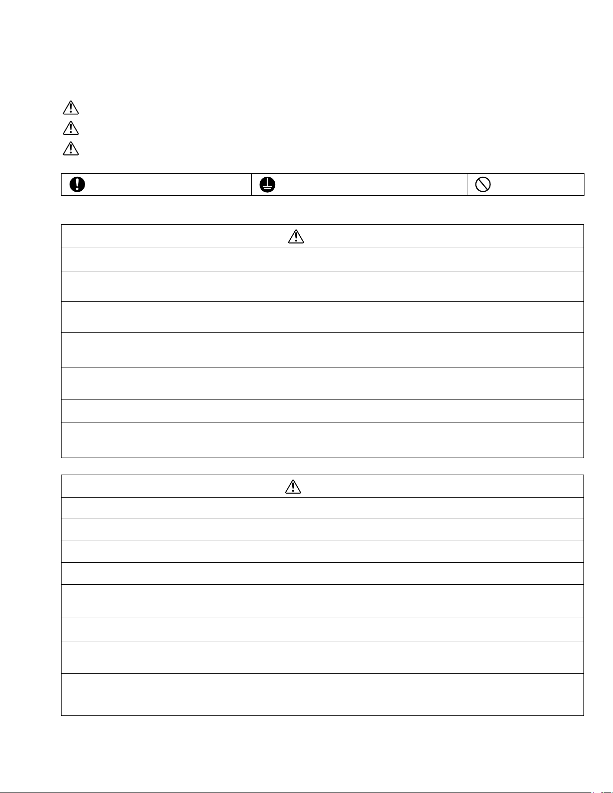
SAFETY PRECAUTIONS
• Read these Safety Precautions carefully to ensure correct installation.
• This manual classifies the precautions into DANGER, WARNING and CAUTION.
Be sure to follow all the precautions below: they are all important for ensuring safety.
DANGER
WARNING
CAUTION ..............Failure to follow any of CAUTION may in some cases result in grave consequences.
................. Indicates an imminently hazardous situation which, if not avoided, will result in death or serious injury.
...............Failure to follow any of WARNING is likely to result in such grave consequences as death or serious injury.
• The following safety symbols are used throughout this manual:
Be sure to observe this instruction.
• After completing installation, test the unit to check for installation errors. Give the user adequate instructions concerning the use
and cleaning of the unit according to the Operation Manual.
Be sure to establish an earth connection. Never attempt.
DANGER
• Refrigerant gas is heavier than air and replaces oxygen. A massive leak could lead to oxygen depletion, especially
in basements, and an asphyxiation hazard could occur leading to serious injury or death.
• If the refrigerant gas leaks during installation, ventilate the area immediately.
Refrigerant gas may produce a toxic gas if it comes in contact with fire such as from a fan heater, stove or cooking device. Exposure to this gas
could cause severe injury or death.
• After completing the installation work, check that the refrigerant gas does not leak.
Refrigerant gas may produce a toxic gas if it comes in contact with fire such as from a fan heater, stove or cooking device. Exposure to this gas
could cause severe injury or death.
• Do not ground units to water pipes, telephone wires or lightning rods because incomplete grounding could cause a
severe shock hazard resulting in severe injury or death, and to gas pipes because a gas leak could result in an
explosion which could lead to severe injury or death.
• Safely dispose of the packing materials.
Packing materials, such as nails and other metal or wooden parts, may cause stabs or other injuries. Tear apart and throw away plastic packaging bags so that children will not play with them. Children playing with plastic bags face the danger of death by suffocation.
• Do not install unit in an area where flammable materials are present due to risk of explosion resulting in serious
injury or death.
• Do not ground units to telephone wires or lightning rods because lightning strikes could cause a severe shock hazard resulting in severe injury or death, and to gas pipes because a gas leak could result in an explosion which
could lead to severe injury or death.
WARNING
• Installation should be left to the authorized dealer or another trained professional.
Improper installation may cause water leakage, electrical shock, fire, or equipment damage.
• Install the air conditioner according to the instructions given in this manual.
Incomplete installation may cause water leakage, electrical shock, fire or equipment damage.
• Be sure to use the supplied or exact specified installation parts.
Use of other parts may cause the unit to come to lose, water leakage, electrical shock, fire or equipment damage.
• Install the air conditioner on a solid base that is level and can support the weight of the unit.
An inadequate base or incomplete installation may cause injury or equipment damage in the event the unit falls off the base or comes loose.
• Electrical work should be carried out in accordance with the installation manual and the national, state and local
electrical wiring codes.
Insufficient capacity or incomplete electrical work may cause electrical shock, fire or equipment damage.
• Be sure to use a dedicated power circuit. Never use a power supply shared by another appliance.
Follow all appropriate electrical codes.
• For wiring, use a wire or cable long enough to cover the entire distance with no splices if possible. Do not use an
extension cord. Do not put other loads on the power supply. Use a only a separate dedicated power circuit.
(Failure to do so may cause abnormal heat, electric shock, fire or equipment damage.)
• Use the specified types of wires for electrical connections between the indoor and outdoor units. Follow all state
and local electrical codes.
Firmly clamp the interconnecting wires so their terminals receive no external stresses. Incomplete connections or clamping may cause terminal
overheating, fire or equipment damage.
1
SAFETY PRECAUTIONS
WARNING
• After connecting all wiring be sure to shape the cables so that they do not put undue stress on the electrical covers, panels or terminals.
Install covers over the wires. Incomplete cover installation may cause terminal overheating, electrical shock,fire or equipment damage.
• When installing or relocating the system, be sure to keep the refrigerant circuit free from all substances other than
the specified refrigerant (R410A), such as air.
(Any presence of air or other foreign substance in the refrigerant circuit causes an abnormal pressure rise which may result in rupture, resulting
in injury.)
• During pump-down, stop the compressor before removing the refrigerant piping.
If the compressor is still running and the shut-off valve is open during pump-down, air will be sucked in when the refrigerant piping is removed,
causing abnormally high pressure which could lead to equipment damage or and personal injury.
• During installation, attach the refrigerant piping securely before running the compressor.
If the compressor is not attached and the shut-off valve is open during pump-down, air will be sucked in when the compressor is run, causing
abnormally high pressure which could lead to equipment damage and personal injury.
• Install a leak circuit breaker, as required.
If a leak circuit breaker is not installed, electric shock may result.
• Be sure to install a ground fault circuit interrupter breaker.
Failure to install a ground fault circuit interrupter breaker may result in electrically shocks or personal injury.
CAUTION
• Establish drain piping according to the instructions of this manual.
Inadequate piping may cause water damage.
• Note for installing the outdoor unit. (For heat pump model only.)
In regions of the country where the outside temperature is at or below the freezing point, the drain may freeze. If so, it is recommended that an
electric heater be installed in order to protect the drain from freezing.
• Tighten the flare nut according to the specified torque. A torque wrench should be used.
If the flare nut is tightened too much, the flare nut may crack over time and cause refrigerant leakage.
• Do not touch the heat exchanger fins.
Improper handling may result in injury.
• Be very careful about product transportation.
Some products use PP bands for packaging. Do not use any PP bands for a means of transportation. It is dangerous.
2
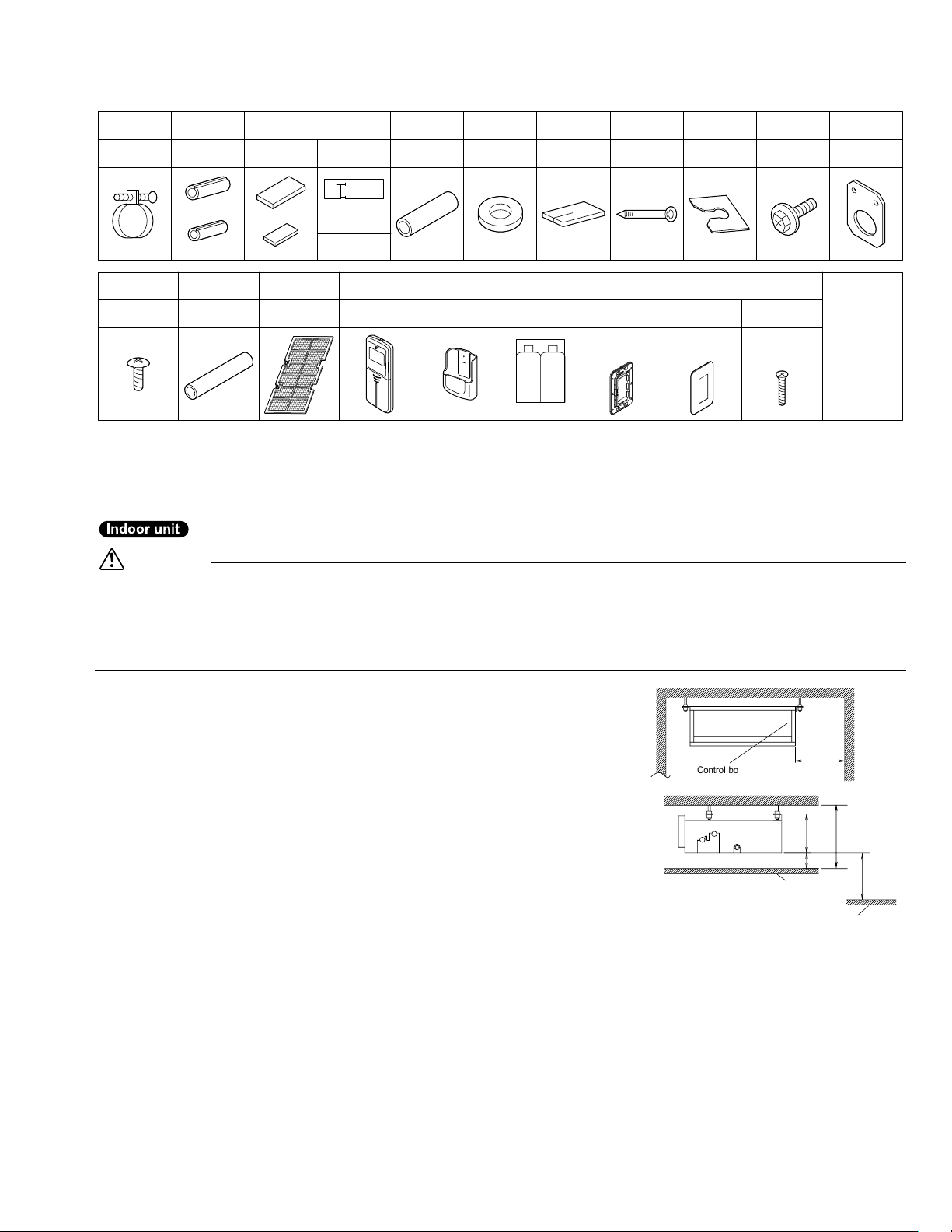
ACCESSORIES
Clamp metal
1 pc. 1 pc.
Screws for conduit
mounting plate
2 pcs.
Insulation
for fitting
1 each
for gas pipe
for liquid pipe
Insulation tube
1 pc.
Sealing pad
Large and small
1 each
Large
Small 24 pcs.4 pcs.
1 pc.
Hanger (right)
insulation
Stored in
outlet vent
Wireless
remote controller
1 pc.
Drain hose
Remote
controller holder
1 pc.1 pc. 1 pc.
Washer for
hanger bracket
8 pcs. 2 pcs. 6 pcs. 1 set
AAA dry-cell
Sealing
material
batteries
1 set 1 pc. 2 pcs.
2 pcs.
Clamp
Mounting
frame
Receiver kitAir fillter
Decorative
cover
Washer
fixing plate
Screws for
duct flanges
1 set
Screws
M4 × 25
• Operation
• Installation
CHOOSING A SITE
• Before choosing the installation site, obtain user approval.
Indoor unit
Caution
• When moving the unit during or after unpacking, make sure to lift it by holding its lifting lugs. Do not exert any pressure on
other parts, especially the refrigerant piping, drain piping and flange parts.
Wear protective gears (gloves and so on) when installing the unit.
• If you think the humidity inside the ceiling might exceed 86°F and RH80%, reinforce the insulation on the unit body.
Use glass wool or polyethylene foam as insulation so that the thickness is more than 0.4in and fits inside the ceiling opening.
Conduit
mounting plate
1 pc.
[ Other ]
manual
manual
• Optimum air distribution is ensured.
• The air passage is not blocked.
• Condensate can drain properly.
• The ceiling is strong enough to bear the weight of the indoor unit.
• A false ceiling does not seem to be at an incline.
• Sufficient clearance for maintenance and servicing is ensured.
• Piping between the indoor and outdoor units is within the allowable limits.
(Refer to the installation manual for the outdoor unit.)
• The indoor unit, outdoor unit, power supply wiring and transmission wiring is
at least 3.3ft away from televisions and radios. This prevents image
interference and noise in electrical appliances. (Noise may be generated
depending on the conditions under which the electric wave is generated, even
if a 3.3ft allowance is maintained.)
Use suspension bolts to install the unit. Check whether or not the ceiling is
strong enough to support the weight of the unit. If there is a risk that the
ceiling is not strong enough, reinforce the ceiling before installing the unit.
(Installation pitch is marked on the carton box for installation. Refer to it to check
for points requiring reinforcing.) Select the *H dimension such that a downward
slope of at least 1/100 is ensured as indicated in
“DRAIN PIPING WORK”
.
• The installation pitch is listed on the packing material, and should be
checked when deciding whether to reinforce the location or not.
12
or more
Control box
Maintenance
space
13/16 or more
Ceiling
7-7/8
*H=9-1/2 or more
If there is
100 or more
Floor surface
(length : in)
no ceiling
3
CHOOSING A SITE
Select the signal receiver mounting location according to the following
conditions:
• Install the signal receiver, which has a built-in temperature sensor, near the
intake vent where there is convection of air and it can get an accurate
reading of the room’s temperature. If the intake vent is in another room or
the unit cannot be installed near the intake vent for any other reason, install
it 5ft above the floor on a wall where there is convection.
• In order to get an accurate reading of the room’s temperature, install the
signal receiver in a location where it is not exposed directly to cold or hot air
from the air discharge grille or to direct sunlight.
• Since the receiver has a built-in light receptor to receive signals from the
wireless remote controller, do not mount it in a location where the signal
may be blocked by a curtain, etc.
Caution
If the signal receiver is not installed in a location where there is convection of air, it may be unable to get an accurate reading of the room’s temperature.
Wireless remote controller
• Turn on all the fluorescent lamps in the room, if any, and find the site where remote controller signals are properly received
by the indoor unit (within 13ft).
Outdoor unit
• For outdoor unit installation, see the installation manual supplied with the outdoor unit.
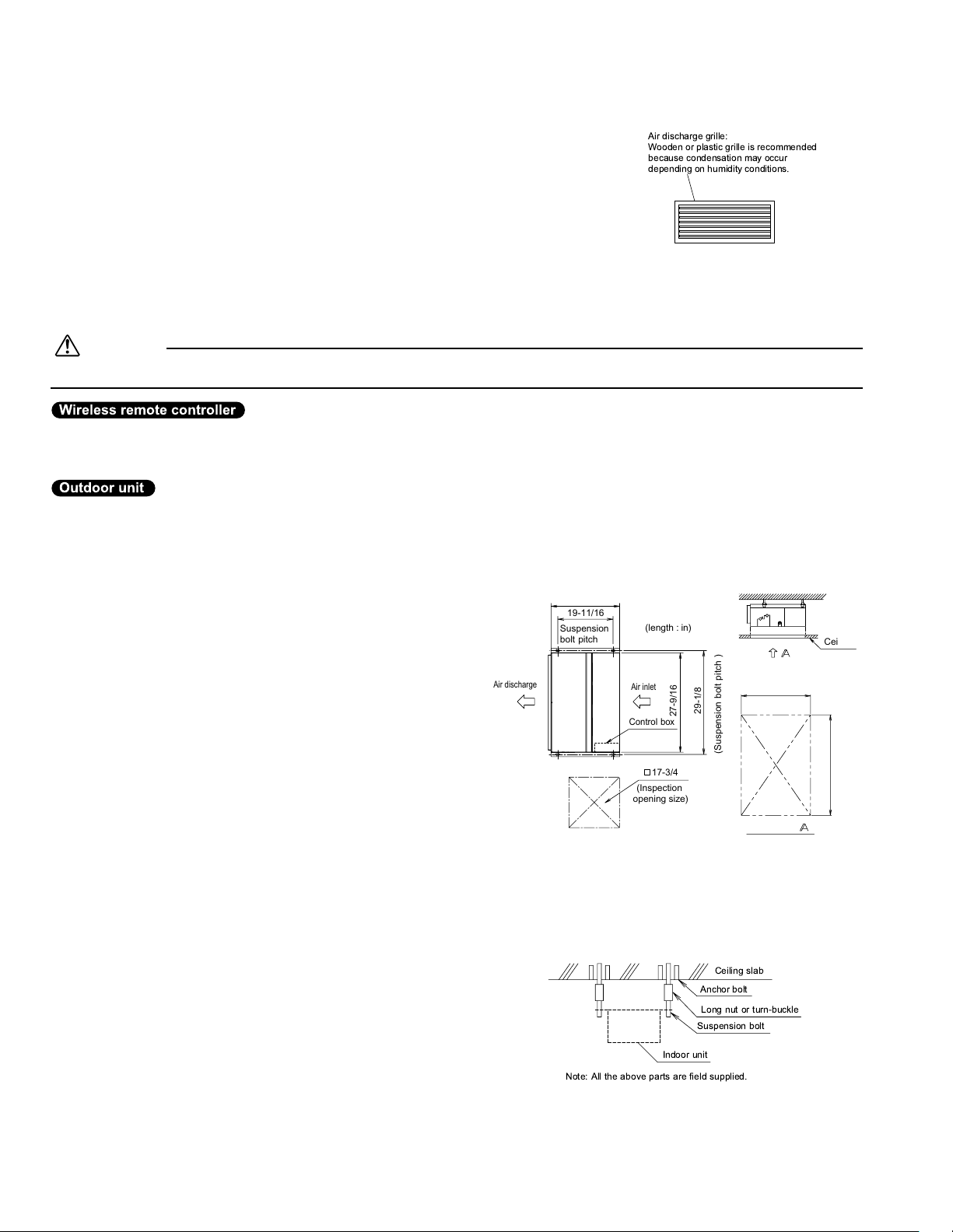
Air discharge grille:
Wooden or plastic grille is recommended
because condensation may occur
depending on humidity conditions.
PREPARATIONS BEFORE INSTALLATION
Relation of the unit to the suspension bolt positions.
• Install the inspection opening on the control box side where
maintenance and inspection of the control box are easy. Install
the inspection opening also in the lower part of the unit.
Make sure the range of the unit’s external static
pressure is not exceeded.
(See the technical documentation for the range of the external
static pressure setting.)
Open the installation hole. (Pre-set ceilings)
• Once the installation hole is opened in the ceiling where the unit
is to be installed, pass refrigerant piping, drain piping,
transmission wiring, and remote controller wiring (unneeded if
using a wireless remote controller) to the unit’s piping and
wiring holes.See “REFRIGERANT PIPING WORK”, “DRAIN
PIPING WORK”, and “WIRING”.
• After opening the ceiling hole, make sure ceiling is level if
needed. It might be necessary to reinforce the ceiling frame to
prevent shaking.Consult an architect or carpenter for details.
Install the suspension bolts.
(Use W3/8 to M10 suspension bolts.)
Use a hole-in-anchor, sunken insert, sunken anchor for existing
ceilings, and a sunken insert, sunken anchor or other part to be
procured in the field to reinforce the ceiling to bearing the weight
of the unit. (Refer to Fig.)
Air discharge
24-7/16
19-11/16
Suspension
bolt pitch
Note: All the above parts are field supplied.
(length : in)
Air inlet
Control box
17-3/4
(Inspection
opening size)
Indoor unit
29-1/8
27-9/16
(Suspension bolt pitch )
Ceiling slab
Anchor bolt
Long nut or turn-buckle
Suspension bolt
〈SERVICE SPACE〉
24-7/16
Allow view
Inspection door
(Ceiling opening)
Ceiling
27-9/16
4
 Loading...