

Daikin CTXS12GVJU, FDXS12DVJU, FTXS15DVJU, FTXS18DVJU, FDXS09DVJU Service Manual
...
SiUS12 - 814
[Applied Models]
Inverter Multi : Heat Pump
G-Series

SiUS12-814
Table of Contents i
SUPER MULTI NX
G-Series
zHeat Pump
Indoor Unit
CTXS09GVJU
CTXS12GVJU
FTXS15DVJU
FTXS18DVJU
FDXS09DVJU
FDXS12DVJU
Outdoor Unit
2MXS18GVJU
4MXS32GVJU

SiUS12-814
ii Table of Contents
1. Introduction ................................................................................................ vi
1.1 Safety Considerations ..................................................................................vi
1.2 Using Icons...................................................................................................xi
Part 1 List of Functions ...................................................................1
1. List of Functions ..........................................................................................2
1.1 Heat Pump Model......................................................................................... 2
Part 2 Specifications .......................................................................7
1. Specifications ..............................................................................................8
1.1 Indoor Units .................................................................................................. 8
1.2 Outdoor Units ............................................................................................. 10
Part 3 Printed Circuit Board Connector Wiring Diagram ..............13
1. Printed Circuit Board Connector Wiring Diagram...................................... 14
1.1 Indoor Unit.................................................................................................. 14
1.2 Outdoor Unit ............................................................................................... 18
Part 4 Function and Control...........................................................23
1. Main Functions..........................................................................................24
1.1 Frequency Principle.................................................................................... 24
1.2 Power-Airflow Dual Flaps, Wide Angle Louvers and Auto-Swing .............. 26
1.3 Fan Speed Control for Indoor Units............................................................ 27
1.4 Program Dry Function ................................................................................ 28
1.5 Automatic Operation................................................................................... 29
1.6 Temperature Control .................................................................................. 30
1.7 Night Set Mode........................................................................................... 31
1.8 INTELLIGENT EYE .................................................................................... 32
1.9 HOME LEAVE Operation ........................................................................... 34
1.10 Inverter POWERFUL Operation ................................................................. 35
1.11 Other Functions.......................................................................................... 35
2. Function of Thermistor .............................................................................. 38
2.1 Heat Pump Model....................................................................................... 38
3. Control Specification .................................................................................40
3.1 Mode Hierarchy .......................................................................................... 40
3.2 Frequency Control...................................................................................... 41
3.3 Controls at Mode Changing / Start-up........................................................ 43
3.4 Discharge Pipe Control .............................................................................. 44
3.5 Input Current Control.................................................................................. 44
3.6 Freeze-up Protection Control ..................................................................... 45
3.7 Heating Peak-cut Control ........................................................................... 45
3.8 Fan Control................................................................................................. 46
3.9 Moisture Protection Function 2................................................................... 46
3.10 Defrost Control ........................................................................................... 47
3.11 Low Hz High Pressure Limit ....................................................................... 49
3.12 Electronic Expansion Valve Control ........................................................... 50

SiUS12-814
Table of Contents iii
3.13 Malfunctions ............................................................................................... 54
3.14 Forced Operation Mode ............................................................................. 55
3.15 Wiring-Error Check..................................................................................... 56
3.16 Additional Functions ................................................................................... 58
Part 5 Operation Manual................................................................61
1. System Configuration................................................................................62
1.1 Operation Instructions ................................................................................ 62
2. Instruction..................................................................................................63
2.1 Manual Contents and Reference Page ...................................................... 63
2.2 Safety Precautions ..................................................................................... 64
2.3 Names of Parts........................................................................................... 66
2.4 Preparation Before Operation .................................................................... 75
2.5 AUTO · DRY · COOL · HEAT · FAN Operation .......................................... 78
2.6 Adjusting the Airflow Direction.................................................................... 80
2.7 POWERFUL Operation .............................................................................. 82
2.8 OUTDOOR UNIT QUIET Operation........................................................... 83
2.9 HOME LEAVE Operation ........................................................................... 84
2.10 INTELLIGENT EYE Operation ................................................................... 86
2.11 TIMER Operation ....................................................................................... 88
2.12 Note for Multi System ................................................................................. 90
2.13 Care and Cleaning ..................................................................................... 92
2.14 Troubleshooting........................................................................................ 100
Part 6 Service Diagnosis..............................................................103
1. Caution for Diagnosis..............................................................................104
1.1 Troubleshooting with the Operation Lamp ............................................... 104
2. Problem Symptoms and Measures .........................................................106
3. Service Check Function .......................................................................... 107
4. Code Indication on the Remote Controller ..............................................110
4.1 Error Codes and Description of Fault ....................................................... 110
5. Troubleshooting ......................................................................................111
5.1 Indoor Units .............................................................................................. 111
5.2 Outdoor Units ........................................................................................... 112
5.3 Indoor Unit PCB Abnormality ................................................................... 114
5.4 Freeze-up Protection Control or High Pressure Control........................... 115
5.5 Fan Motor or Related Abnormality ........................................................... 117
5.6 Thermistor or Related Abnormality (Indoor Unit)...................................... 121
5.7 Signal Transmission Error (between Indoor and Outdoor Units).............. 122
5.8 Unspecified Voltage (between Indoor and Outdoor Units)....................... 124
5.9 Freeze-up Protection Control ................................................................... 125
5.10 Outdoor Unit PCB Abnormality................................................................. 127
5.11 OL Activation (Compressor Overload) ..................................................... 128
5.12 Compressor Lock ..................................................................................... 129
5.13 DC Fan Lock ............................................................................................ 130
5.14 Input Over Current Detection ................................................................... 131
5.15 Four-Way Valve Abnormality.................................................................... 133

SiUS12-814
iv Table of Contents
5.16 Discharge Pipe Temperature Control....................................................... 135
5.17 High Pressure Control in Cooling ............................................................. 136
5.18 Compressor Sensor System Abnormality ................................................ 138
5.19 Position Sensor Abnormality .................................................................... 140
5.20 CT or Related Abnormality ....................................................................... 141
5.21 Thermistor or Related Abnormality (Outdoor Unit)................................... 143
5.22 Electrical Box Temperature Rise.............................................................. 145
5.23 Radiation Fin Temperature Rise .............................................................. 147
5.24 Output Over Current Detection................................................................. 149
5.25 Insufficient Gas......................................................................................... 151
5.26 Low-voltage Detection or Over-voltage Detection.................................... 155
5.27 Signal Transmission Error (on Outdoor Unit PCB)................................... 156
5.28 Anti-icing Function in Other Rooms / Unspecified Voltage
(between Indoor and Outdoor Units)........................................................ 157
6. Check ......................................................................................................158
6.1 How to Check ........................................................................................... 158
Part 7 Removal Procedure...........................................................169
1. Outdoor Unit – 2MXS18GVJU ................................................................170
1.1 Removal of Outer Panels ......................................................................... 170
1.2 Removal of Electrical BOX ....................................................................... 171
1.3 Removal of PCB....................................................................................... 176
1.4 Removal of Fan Motor.............................................................................. 180
1.5 Removal of Sound Insulation ................................................................... 181
1.6 Removal of Four-Way Valve Coil, Solenoid Valve Coil,
Electronic Expansion Valve Coil and Thermistor ..................................... 183
1.7 Removal of Four-Way Valve, Solenoid Valve and Shunt ......................... 185
1.8 Removal of Compressor........................................................................... 187
2. Outdoor Unit – 4MXS32GVJU ................................................................189
2.1 Removal of Outer Panels ......................................................................... 189
2.2 Removal of the Electrical Box .................................................................. 205
2.3 Removal of PCB....................................................................................... 211
2.4 Removal of Fan Motor.............................................................................. 215
2.5 Removal of Coils / Thermistors ................................................................ 216
2.6 Removal of Sound Blanket....................................................................... 222
2.7 Removal of Compressor........................................................................... 225
Part 8 Others ................................................................................227
1. Others .....................................................................................................228
1.1 Test Run from the Remote Controller ...................................................... 228
1.2 Jumper Settings ....................................................................................... 229
1.3 Application of Silicon Grease to a Power Transistor and
a Diode Bridge.......................................................................................... 230
Part 9 Appendix............................................................................231
1. Piping Diagrams......................................................................................232

SiUS12-814
Table of Contents v
1.1 Indoor Units .............................................................................................. 232
1.2 Outdoor Units ........................................................................................... 233
2. Wiring Diagrams......................................................................................234
2.1 Indoor Units .............................................................................................. 234
2.2 Outdoor Units ........................................................................................... 236
Index ................................................................................................i
Drawings & Flow Charts ................................................................... v
Introduction SiUS12-814
vi
1. Introduction
1.1 Safety Considerations
Read these SAFETY CONSIDERATIONS carefully before installing air conditioning equipment
and be sure to install it correctly. After completing the installation, make sure that the unit operates
properly during the start-up operation.
Instruct the customer on how to operate and maintain the unit.
Inform customers that they should store this Installation Manual along with the Operation Manual
for future reference.
Always use a licensed installer or contractor to install this product. Improper installation can result
in water or refrigerant leakage, electrical shock, fire, or explosion.
Meanings of danger, warning, caution and DANGER, WARNING, CAUTION, and NOTE symbols:
DANGER Indicates an imminently hazardous situation that if not avoided, will result in
death or serious injury.
WARNING Indicates a potentially hazardous situation that if not avoided, could result in death
or serious injury.
CAUTION Indicates a potentially hazardous situation that if not avoided, may result in minor
or moderate injury. It may also be used to alert against unsafe practices.
NOTE Indicates a situation that may result in equipment or property damage accidents only.
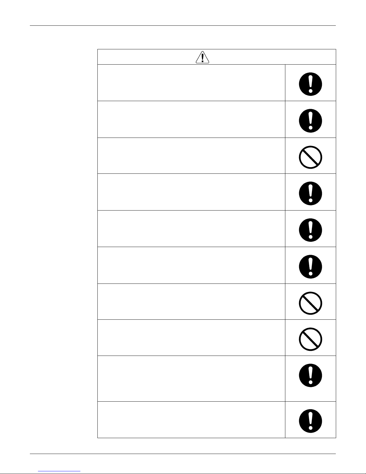
1.1.1 Cautions Regarding Safety of Workers
Warning
Be sure to disconnect the power cable plug from the plug socket before
disassembling the equipment for repair.
Working on the equipment that is connected to the power supply may cause an
electrical shook.
If it is necessary to supply power to the equipment to conduct the repair or
inspecting the circuits, do not touch any electrically charged sections of the
equipment.
If the refrigerant gas is discharged during the repair work, do not touch the
discharged refrigerant gas.
The refrigerant gas may cause frostbite.
When disconnecting the suction or discharge pipe of the compressor at the
welded section, evacuate the refrigerant gas completely at a well-ventilated
place first.
If there is a gas remaining inside the compressor, the refrigerant gas or
refrigerating machine oil discharges when the pipe is disconnected, and it may
cause injury.
If the refrigerant gas leaks during the repair work, ventilate the area. The
refrigerant gas may generate toxic gases when it contacts flames.
The step-up capacitor supplies high-voltage electricity to the electrical
components of the outdoor unit.
Be sure to discharge the capacitor completely before conducting repair work.
A charged capacitor may cause an electrical shock.
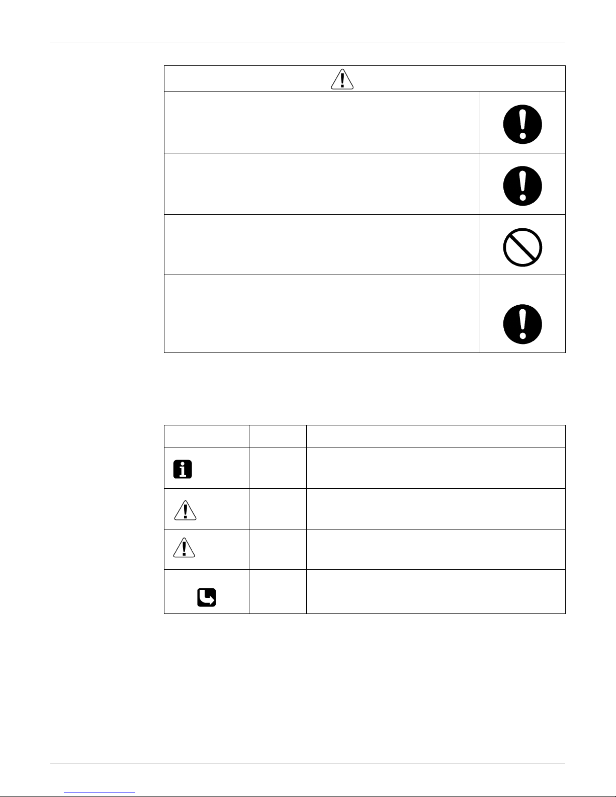
SiUS12-814 Introduction
vii
Do not start or stop the air conditioner operation by plugging or unplugging the
power cable plug.
Plugging or unplugging the power cable plug to operate the equipment may
cause an electrical shock or fire.
Be sure to wear a safety helmet, gloves, and a safety belt when working at a
high place (more than 2m). Insufficient safety measures may cause a fall
accident.
In case of R410A refrigerant models, be sure to use pipes, flare nuts and tools
for the exclusive use of the R410A refrigerant.
The use of materials for R22 refrigerant models may cause a serious accident
such as a damage of refrigerant cycle as well as an equipment failure.
Warning
Caution
Do not repair the electrical components with wet hands.
Working on the equipment with wet hands may cause an electrical shock.
Do not clean the air conditioner by splashing water.
Washing the unit with water may cause an electrical shock.
Be sure to provide the grounding when repairing the equipment in a humid or
wet place, to avoid electrical shocks.
Be sure to turn off the power switch and unplug the power cable when cleaning
the equipment.
The internal fan rotates at a high speed, and cause injury.
Be sure to conduct repair work with appropriate tools.
The use of inappropriate tools may cause injury.
Be sure to check that the refrigerating cycle section has cooled down enough
before conducting repair work.
Working on the unit when the refrigerating cycle section is hot may cause
burns.
Introduction SiUS12-814
viii
Use the welder in a well-ventilated place.
Using the welder in an enclosed room may cause oxygen deficiency.
Caution
SiUS12-814 Introduction
ix
1.1.2 Cautions Regarding Safety of Users
Warning
Be sure to use parts listed in the service parts list of the applicable model and
appropriate tools to conduct repair work. Never attempt to modify the
equipment.
The use of inappropriate parts or tools may cause an electrical shock,
excessive heat generation or fire.
If the power cable and lead wires have scratches or deteriorated, be sure to
replace them.
Damaged cable and wires may cause an electrical shock, excessive heat
generation or fire.
Do not use a joined power cable or extension cable, or share the same power
outlet with other electrical appliances, since it may cause an electrical shock,
excessive heat generation or fire.
Be sure to use an exclusive power circuit for the equipment, and follow the local
technical standards related to the electrical equipment, the internal wiring
regulations, and the instruction manual for installation when conducting
electrical work.
Insufficient power circuit capacity and improper electrical work may cause an
electrical shock or fire.
Be sure to use the specified cable for wiring between the indoor and outdoor
units. Make the connections securely and route the cable properly so that there
is no force pulling the cable at the connection terminals.
Improper connections may cause excessive heat generation or fire.
When wiring between the indoor and outdoor units, make sure that the terminal
cover does not lift off or dismount because of the cable.
If the cover is not mounted properly, the terminal connection section may cause
an electrical shock, excessive heat generation or fire.
Do not damage or modify the power cable.
Damaged or modified power cable may cause an electrical shock or fire.
Placing heavy items on the power cable, and heating or pulling the power cable
may damage the cable.
Do not mix air or gas other than the specified refrigerant (R410A / R22) in the
refrigerant system.
If air enters the refrigerating system, an excessively high pressure results,
causing equipment damage and injury.
If the refrigerant gas leaks, be sure to locate the leaking point and repair it
before charging the refrigerant. After charging refrigerant, make sure that there
is no refrigerant leak.
If the leaking point cannot be located and the repair work must be stopped, be
sure to perform pump-down and close the service valve, to prevent the
refrigerant gas from leaking into the room. The refrigerant gas itself is
harmless, but it may generate toxic gases when it contacts flames, such as fan
and other heaters, stoves and ranges.
When relocating the equipment, make sure that the new installation site has
sufficient strength to withstand the weight of the equipment.
If the installation site does not have sufficient strength and if the installation
work is not conducted securely, the equipment may fall and cause injury.

Introduction SiUS12-814
x
Check to make sure that the power cable plug is not dirty or loose, then insert
the plug into a power outlet securely.
If the plug has dust or loose connection, it may cause an electrical shock or fire.
Be sure to install the product correctly by using the provided standard
installation frame.
Incorrect use of the installation frame and improper installation may cause the
equipment to fall, resulting in injury.
For unitary type
only
Be sure to install the product securely in the installation frame mounted on the
window frame.
If the unit is not securely mounted, it may fall and cause injury.
For unitary type
only
When replacing the coin battery in the remote controller, be sure to disposed
of the old battery to prevent children from swallowing it.
If a child swallows the coin battery, see a doctor immediately.
Warning
Caution
Installation of a GFCI is necessary in some cases depending on the conditions
of the installation site, to prevent electrical shocks.
Do not install the equipment in a place where there is a possibility of
combustible gas leaks.
If the combustible gas leaks and remains around the unit, it may cause a fire.
Check to see if the parts and wires are mounted and connected properly, and
if the connections at the soldered or crimped terminals are secure.
Improper installation and connections may cause excessive heat generation,
fire or an electrical shock.
If the installation platform or frame has corroded, replace it.
Corroded installation platform or frame may cause the unit to fall, resulting in
injury.
Check the grounding, and repair it if the equipment is not properly grounded.
Improper grounding may cause an electrical shock.
SiUS12-814 Introduction
xi
1.2 Using Icons
Icons are used to attract the attention of the reader to specific information. The meaning of each
icon is described in the table below:
Be sure to measure the insulation resistance after the repair, and make sure
that the resistance is 1 MΩ or higher.
Faulty insulation may cause an electrical shock.
Be sure to check the drainage of the indoor unit after the repair.
Faulty drainage may cause the water to enter the room and wet the furniture
and floor.
Do not tilt the unit when removing it.
The water inside the unit may spill and wet the furniture and floor.
Be sure to install the packing and seal on the installation frame properly.
If the packing and seal are not installed properly, water may enter the room and
wet the furniture and floor.
For unitary type
only
Caution
Icon Type of
Information
Description
Note:
Note A note provides information, techniques, and tips to best
understand and utilize the equipment.
Caution
Caution Indicates a potentially hazardous situation which, if not avoided,
may result in minor or moderate injury. It may also be used to
alert against unsafe practices that may cause property damage.
Warning
Warning Indicates a potentially hazardous situation which, if not avoided,
could result in death or serious injury. This signal word should
not be used for property damage hazards unless personal injury
risk appropriate to this level is also involved.
Reference A reference guides the reader to other places in this binder or in
this manual, where he/she will find additional information on a
specific topic.

Introduction SiUS12-814
xii

SiUS12-814
List of Functions 1
Part 1
List of Functions
1. List of Functions ..........................................................................................2
1.1 Heat Pump Model......................................................................................... 2
List of Functions SiUS12-814
2 List of Functions
1. List of Functions
1.1 Heat Pump Model
Category Functions
CTXS09/12GVJU
Category Functions
CTXS09/12GVJU
Basic Function
Inverter (with Inverter Power Control) {
Health &
Clean
Air Purifying Filter —
Operation Limit for Cooling (°FDB) —
Operation Limit for Heating (°FWB) — Photocatalytic Deodorizing Filter —
Air Purifying Filter with Photocatalytic
Deodorizing Function
{PAM Control —
Compressor
Oval Scroll Compressor —
Titanium Apatite Photocatalytic
Air-Purifying Filter
—
Swing Compressor —
Rotary Compressor — Mold Proof Air Filter {
Reluctance DC Motor — Wipe-clean Flat Panel {
Comfortable
Airflow
Power-Airflow Louver — Washable Grille —
Power-Airflow Dual Louvers { Filter Cleaning Indicator —
Power-Airflow Diffuser — Good-Sleep Cooling Operation —
Wide-Angle Louvers {
Timer
24-Hour On/Off Timer {
Vertical Auto-Swing (Up and Down) { Night Set Mode {
Horizontal Auto-Swing (Right and Left) {
Worry Free
“Reliability &
Durability”
Auto-Restart (after Power Failure) {
3-D Airflow {
Self-Diagnosis (Digital, LED) Display {
Comfort Airflow Mode —
3-Step Airflow (H/P Only) — Wiring Error Check —
Comfort
Control
Auto Fan Speed {
Anticorrosion Treatment of Outdoor Heat
Exchanger
—
Indoor Unit Quiet Operation {
Night Quiet Mode (Automatic) —
Flexibility
Multi-Split / Split Type Compatible Indoor Unit —
Outdoor Unit Quiet Operation (Manual) — Flexible Voltage Correspondence —
INTELLIGENT EYE { High Ceiling Application —
Quick Warming Function — *Chargeless —
Hot-Start Function { Either Side Drain (Right or Left) {
Automatic Defrosting — Power Selection —
Operation
Automatic Operation {
Remote
Control
5-Rooms Centralized Controller (Option) {
Program Dry Function {
Remote Control Adapter
(Normal Open-Pulse Contact) (Option)
{
Fan Only {
Lifestyle
Convenience
New POWERFUL Operation (Non-Inverter) —
Remote Control Adapter
(Normal Open Contact) (Option)
{
Inverter POWERFUL Operation {
Priority-Room Setting — DIII-NET Compatible (Adapter) (Option)
{
Cooling / Heating Mode Lock —
Remote
Controller
Wireless {
HOME LEAVE Operation { Wired —
Indoor Unit On/Off Switch {
Signal Reception Indicator {
Temperature Display —
Another Room Operation —
Note: { : Holding Functions
— : No Functions
* Chargeless = Allowable pipe length before additional refrigerant is necessary.
SiUS12-814 List of Functions
List of Functions 3
Category Functions
FTXS15/18DVJU
Category Functions
FTXS15/18DVJU
Basic Function
Inverter (with Inverter Power Control) {
Health &
Clean
Air Purifying Filter —
Operation Limit for Cooling (°FDB) — Photocatalytic Deodorizing Filter —
Operation Limit for Heating (°FWB) —
Air Purifying Filter with Photocatalytic
Deodorizing Function
{
PAM Control —
Titanium Apatite Photocatalytic
Air-Purifying Filter
—
Compressor
Oval Scroll Compressor —
Swing Compressor — Mold Proof Air Filter {
Rotary Compressor — Wipe-clean Flat Panel {
Reluctance DC Motor — Washable Grille —
Comfortable
Airflow
Power-Airflow Louver — Filter Cleaning Indicator —
Power-Airflow Dual Louvers { Good-Sleep Cooling Operation —
Power-Airflow Diffuser —
Timer
24-Hour On/Off Timer {
Wide-Angle Louvers { Night Set Mode {
Vertical Auto-Swing (Up and Down) {
Worry Free
“Reliability &
Durability”
Auto-Restart (after Power Failure) {
Horizontal Auto-Swing (Right and Left) { Self-Diagnosis (Digital, LED) Display {
3-D Airflow { Wiring Error Check —
Comfort Airflow Mode —
Anticorrosion Treatment of Outdoor Heat
Exchanger
—
3-Step Airflow (H/P Only) —
Comfort
Control
Auto Fan Speed {
Flexibility
Multi-Split / Split Type Compatible Indoor Unit {
Indoor Unit Quiet Operation {
Night Quiet Mode (Automatic) — Flexible Voltage Correspondence —
Outdoor Unit Quiet Operation (Manual) — High Ceiling Application —
INTELLIGENT EYE { *Chargeless —
Quick Warming Function — Either Side Drain (Right or Left) {
Hot-Start Function { Power Selection —
Automatic Defrosting —
Remote
Control
5-Rooms Centralized Controller (Option) {
Operation
Automatic Operation {
Remote Control Adapter
(Normal Open-Pulse Contact) (Option)
{
Program Dry Function {
Fan Only {
Remote Control Adapter
(Normal Open Contact) (Option)
{
Lifestyle
Convenience
New POWERFUL Operation (Non-Inverter) —
Inverter POWERFUL Operation { DIII-NET Compatible (Adapter) (Option)
{
Priority-Room Setting —
Remote
Controller
Wireless {
Cooling / Heating Mode Lock — Wired —
HOME LEAVE Operation {
Indoor Unit On/Off Switch {
Signal Reception Indicator {
Temperature Display —
Another Room Operation —
Note: { : Holding Functions
— : No Functions
* Chargeless = Allowable pipe length before additional refrigerant is necessary.
List of Functions SiUS12-814
4 List of Functions
Category Functions
FDXS09/12DVJU
Category Functions
FDXS09/12DVJU
Basic Function
Inverter (with Inverter Power Control) {
Health &
Clean
Air Purifying Filter —
Operation Limit for Cooling (°FDB) —
Operation Limit for Heating (°FWB) — Photocatalytic Deodorizing Filter —
PAM Control —
Air Purifying Filter with Photocatalytic
Deodorizing Function
—
Compressor
Oval Scroll Compressor —
Titanium Apatite Photocatalytic
Air-Purifying Filter
—
Swing Compressor —
Rotary Compressor — Mold Proof Air Filter {
Reluctance DC Motor — Wipe-clean Flat Panel —
Comfortable
Airflow
Power-Airflow Louver — Washable Grille —
Power-Airflow Dual Louvers — Filter Cleaning Indicator —
Power-Airflow Diffuser — Good-Sleep Cooling Operation —
Wide-Angle Louvers —
Timer
24-Hour On/Off Timer {
Vertical Auto-Swing (Up and Down) — Night Set Mode {
Horizontal Auto-Swing (Right and Left) —
Worry Free
“Reliability &
Durability”
Auto-Restart (after Power Failure) {
3-D Airflow — Self-Diagnosis (Digital, LED) Display {
Comfort Airflow Mode — Wiring Error Check —
3-Step Airflow (H/P Only) —
Anticorrosion Treatment of Outdoor Heat
Exchanger
{
Comfort
Control
Auto Fan Speed {
Indoor Unit Quiet Operation —
Flexibility
Multi-Split / Split Type Compatible Indoor Unit —
Night Quiet Mode (Automatic) —
Outdoor Unit Quiet Operation (Manual) { Flexible Voltage Correspondence —
INTELLIGENT EYE — High Ceiling Application —
Quick Warming Function — *Chargeless
33ft
Hot-Start Function { Either Side Drain (Right or Left) —
Automatic Defrosting — Power Selection —
Operation
Automatic Operation {
Remote
Control
5-Rooms Centralized Controller (Option) {
Program Dry Function {
Remote Control Adapter
(Normal Open-Pulse Contact) (Option)
{
Fan Only {
Lifestyle
Convenience
New POWERFUL Operation (Non-Inverter) —
Remote Control Adapter
(Normal Open Contact) (Option)
{
Inverter POWERFUL Operation {
Priority-Room Setting — DIII-NET Compatible (Adapter) (Option) {
Cooling / Heating Mode Lock —
Remote
Controller
Wireless {
HOME LEAVE Operation { Wired —
Indoor Unit On/Off Switch {
Signal Reception Indicator {
Temperature Display —
Another Room Operation —
Note: { : Holding Functions
— : No Functions
* Chargeless = Allowable pipe length before additional refrigerant is necessary.
SiUS12-814 List of Functions
List of Functions 5
Category Functions
2MXS18GVJU
4MXS32GVJU
Category Functions
2MXS18GVJU
4MXS32GVJU
Basic Function
Inverter (with Inverter Power Control) {{
Health &
Clean
Air Purifying Filter — —
Operation Limit for Cooling (°FDB)
14~
114.8
14~
114.8
Operation Limit for Heating (°FWB)
5~
59.95~59.9
Photocatalytic Deodorizing Filter — —
Air Purifying Filter with Photocatalytic
Deodorizing Function
——
PAM Control {{
Compressor
Oval Scroll Compressor — —
Titanium Apatite Photocatalytic
Air-Purifying Filter
——
Swing Compressor {{
Rotary Compressor — — Mold Proof Air Filter — —
Reluctance DC Motor {{ Wipe-clean Flat Panel — —
Comfortable
Airflow
Power-Airflow Louver — — Washable Grille — —
Power-Airflow Dual Louvers — — Filter Cleaning Indicator — —
Power-Airflow Diffuser — — Good-Sleep Cooling Operation — —
Wide-Angle Louvers — —
Timer
24-Hour On/Off Timer — —
Vertical Auto-Swing (Up and Down) — — Night Set Mode — —
Horizontal Auto-Swing (Right and Left) — —
Worry Free
“Reliability &
Durability”
Auto-Restart (after Power Failure) — —
3-D Airflow — —
Self-Diagnosis (Digital, LED) Display {{
Comfort Airflow Mode — —
3-Step Airflow (H/P Only) — — Wiring Error Check {{
Comfort
Control
Auto Fan Speed — —
Anticorrosion Treatment of Outdoor Heat
Exchanger
{{
Indoor Unit Quiet Operation — —
Night Quiet Mode (Automatic) {{
Flexibility
Multi-Split / Split Type Compatible Indoor
Unit
——
Outdoor Unit Quiet Operation (Manual) {{ Flexible Voltage Correspondence — —
Intelligent Eye — — High Ceiling Application — —
Quick Warming Function {{ *Chargeless
98.4ft
131.6ft
Hot-Start Function — — Either Side Drain (Right or Left) — —
Automatic Defrosting {{ Power Selection — —
Operation
Automatic Operation — —
Remote
Control
5-Rooms Centralized Controller (Option) — —
Program Dry Function — —
Remote Control Adapter
(Normal Open-Pulse Contact) (Option)
——
Fan Only — —
Lifestyle
Convenience
New POWERFUL Operation
(Non-Inverter)
——
Remote Control Adapter
(Normal Open Contact) (Option)
——
Inverter POWERFUL Operation — —
Priority-Room Setting {{ DIII-NET Compatible (Adapter) (Option) — —
Cooling / Heating Mode Lock {{
Remote
Controller
Wireless — —
HOME LEAVE Operation — — Wired — —
Indoor Unit On/Off Switch — —
Signal Reception Indicator — —
Temperature Display — —
Another Room Operation — —
Notes: { : Holding Functions
— : No Functions
* Chargeless = Allowable pipe length before additional refrigerant is necessary.

List of Functions SiUS12-814
6 List of Functions

SiUS12-814
Specifications 7
Part 2
Specifications
1. Specifications ..............................................................................................8
1.1 Indoor Units .................................................................................................. 8
1.2 Outdoor Units ............................................................................................. 10
Specifications SiUS12-814
8 Specifications
1. Specifications
1.1 Indoor Units
Wall Mounted Indoor Units
60Hz 208-230V
60Hz 230V
Model
CTXS09GVJU CTXS12GVJU
Cooling Heating Cooling Heating
Rated Capacity 9kBtu/h Class 12kBtu/h Class
Front Panel Color White White
Air Flow Rates cfm (m³/min)
H 388 (11.0) 400 (11.3) 388 (11.0) 400 (11.3)
M 335 (9.5) 357 (10.1) 335 (9.5) 357 (10.1)
L 283 (8.0) 314 (8.9) 283 (8.0) 314 (8.9)
Fan
Type Cross Flow Fan Cross Flow Fan
Motor Output W 40 40
Speed Steps 5 Steps, Quiet, Auto 5 Steps, Quiet, Auto
Air Direction Control Right, Left, Horizontal, Downward Right, Left, Horizontal, Downward
Air Filter Removable / Washable / Mildew Proof Removable / Washable / Mildew Proof
Running Current (Rated) A 0.18 0.2 0.18 0.2
Power Consumption (Rated) W 40 45 40 45
Power Factor % 96.6 97.8 96.6 97.8
Temperature Control Microcomputer Control Microcomputer Control
Dimensions (H×W×D) inch (mm) 11-7/16 × 31-5/16 × 9-3/8” (291 x 795 x 238 mm) 11-7/16 × 31-5/16 × 9-3/8” (291 x 795 x 238 mm)
Packaged Dimensions (H×W×D) inch (mm) 11 × 33-1/16 × 13-5/16” (279 x 840 x 338 mm) 11 × 33-1/16 × 13-5/16” (279 x 840 x 338 mm)
Weight Lbs 20 lbs (20 kg) 20 lbs (20 kg)
Gross Weight Lbs 29 lbs (13.2 kg) 29 lbs (13.2 kg)
Operation Sound H/M/L dBA 44/40/35 44/39/34 45/41/36 45/40/35
Heat Insulation Both Liquid and Gas Pipes Both Liquid and Gas Pipes
Piping Connection
Liquid inch (mm)
φ
1/4” (6.4 mm)
φ
1/4” (6.4 mm)
Gas inch (mm)
φ 3/8” (9.5 mm) φ 3/8” (9.5 mm)
Drain inch (mm)
φ 11/16” (17.5 mm) φ 11/16” (17.5 mm)
Drawing No. 3D058830 3D058831
Model
FTXS15DVJU FTXS18DVJU
Cooling Heating Cooling Heating
Rated Capacity 15kBtu/h Class 18kBtu/h Class
Front Panel Color White White
Air Flow Rates cfm (m³/min)
H 519 (14.7) 515 (14.6) 549 (15.5) 609 (17.2)
M 436 (12.3) 459 (13.0) 476 (13.5) 529 (15.0)
L 353 (10.0) 402 (11.4) 402 (11.4) 448 (12.7)
Fan
Type Cross Flow Fan Cross Flow Fan
Motor Output W 43 43
Speed Steps 5 Steps, Quiet, Auto 5 Steps, Quiet, Auto
Air Direction Control Right, Left, Horizontal, Downward Right, Left, Horizontal, Downward
Air Filter Removable / Washable / Mildew Proof Removable / Washable / Mildew Proof
Running Current (Rated) A 0.18 0.18
Power Consumption (Rated) W 40 40
Power Factor % 96.6 96.6
Temperature Control Microcomputer Control Microcomputer Control
Dimensions (H×W×D) inch (mm) 11-7/16 × 41-5/16 × 9-3/8” (291 x 1049 x 238 mm) 11-7/16 × 41-5/16 × 9-3/8” (291 x 1049 x 238 mm)
Packaged Dimensions (H×W×D) inch (mm) 13-1/4 × 45-3/16 × 14-7/16” (337 x 1148 x 367 mm) 13-1/4 × 45-3/16 × 14-7/16” (337 x 1148 x 367 mm)
Weight Lbs (kg) 26.5 lbs (12 kg) 26.5
Gross Weight Lbs (kg) 38 lbs (17 kg) 38
Operation Sound H/M/L dBA 45/41/36 44/40/35 45/41/36 44/40/35
Heat Insulation Both Liquid and Gas Pipes Both Liquid and Gas Pipes
Piping Connection
Liquid inch (mm)
φ
1/4” (6.4 mm)
φ
1/4” (6.4 mm)
Gas inch (mm)
φ
1/2” (12.7 mm)
φ
1/2” (12.7 mm)
Drain inch (mm)
φ 11/16” (17.5 mm) φ 11/16” (17.5 mm)
Drawing No. 3D056381 3D056382
Conversion Formula
kcal/h=kW×860
Btu/h=kW×3414
cfm=m³/min×35.3
SiUS12-814 Specifications
Specifications 9
Slim Concealed Ceiling-Mounted Indoor Units
60Hz 230V
Model
FDXS09DVJU FDXS12DVJU
Cooling Heating Cooling Heating
Rated Capacity 9kBtu/h Class 12kBtu/h Class
External Static Pressure Pa 30 30
Air Flow Rates cfm
H 305 305 305 305
M 280 280 280 280
L 260 260 260 260
Fan
Type Sirocco Fan Sirocco Fan
Motor Output W 62 62
Speed Steps 5 Steps, Quiet, Auto 5 Steps, Quiet, Auto
Air Filter Removable / Washable / Mildew Proof Removable / Washable / Mildew Proof
Running Current (Rated) A 0.52 0.52 0.52 0.52
Power Consumption (Rated) W 72 72 72 72
Power Factor % 60.2 60.2 60.2 60.2
Temperature Control Microcomputer Control Microcomputer Control
Dimensions (H×W×D) inch (mm) 7-7/8 × 27-9/16 × 24-7/16” (200 x 700 x 621 mm) 7-7/8 × 27-9/16 × 24-7/16” (200 x 700 x 621 mm)
Packaged Dimensions (H×W×D) inch (mm) 10-13/16 × 30-1/4 × 36-5/16” (272 x 768 x 906 mm) 10-13/16 × 30-1/4 × 36-5/16” (272 x 768 x 906 mm)
Weight Lbs (kg) 47 lbs (21.3 kg) 47 lbs (21.3 kg)
Gross Weight Lbs (kg) 64 lbs (29 kg) 64 lbs (29 kg)
Operation Sound H/M/L dBA 35/33/31 35/33/31 35/33/31 35/33/31
Heat Insulation Both Liquid and Gas Pipes Both Liquid and Gas Pipes
Piping Connection
Liquid inch (mm)
φ
1/4” (6.4 mm)
φ
1/4” (6.4 mm)
Gas inch (mm)
φ 3/8
” (9.5 mm)
φ 3/8
” (9.5 mm)
Drain inch (mm) O.D.1-1/32, I.D.25/32 O.D.1-1/32, I.D.25/32
Drawing No. 3D051781A 3D051782A
Conversion Formulae
kcal/h=kW×860
Btu/h=kW×3414
cfm=m³/min×35.3

Specifications SiUS12-814
10 Specifications
1.2 Outdoor Units
60Hz 208-230V
Note: 1. The data are based on the conditions shown in the table below.
Model
2MXS18GVJU
Cooling Heating
Capacity kW —
Power Consumption W —
Running Current A —
Casing Color Ivory White
Compressor
Type Hermetically Sealed Swing Type
Model 2YC45EXD
Motor Output W 1,380
Refrigerant Oil
Model FVC50K
Charge oz 26.5
Refrigerant
Type R-410A
Charge Lbs 5.73
Air Flow Rate
m³/min
H49 41
M— —
L43 39
cfm
H 1,730 1,448
M— —
L 1,518 1,377
Fan
Type Propeller
Motor Output W 53
Starting Current A 10.6
Dimension (H×W×D) inch (mm) 28-15/16 × 32-1/2 × 11-13/16” (736 x 825.5 x 300 mm)
Packaged Dimension (H×W×D) inch (mm) 15-3/8 × 31-7/16 × 39-5/16” (390.5 x 951 x 999 mm)
Weight Lbs (kg) 139 lbs (63 kg)
Gross Weight Lbs (kg) 144 lbs (65 kg)
Operation Sound (Sound Pressure) dBA 50 51
Piping Connection
Liquid inch (mm) φ 1/4” (6.4 mm)× 2
Gas inch (mm) φ 3/8” (9.5 mm) × 2
Drain inch (mm) φ11/16” (17.4 mm)
Heat Insulation Both Liquid & Gas Pipes
No. of Wiring Connection 3 for Power Supply, 4 for Interunit Wiring
Max. Piping Length ft (m)
164’ (50 m) (for Total of Each Room)
82’ (25 m) (for One Room)
Amount of Additional Charge oz/ft (gram/m) 0.22 oz / 6.2 grams (98.4 ft/ 30 m or more)
Max. Installation Height Difference ft (m)
49.2 ft (15 m) (between Indoor Unit and Outdoor Unit)
24.6 ft (7.5 m) (between Indoor Units)
Drawing No. 3D058840
Conversion Formulae
kcal/h=kW×860
Btu/h=kW×3414
cfm=m³/min×35.3
Cooling Heating Piping Length
Indoor ; 80°FDB/67°FWB
Outdoor ; 95°FDB/75°FWB
Indoor ; 70°FDB/60°FWB
Outdoor ; 47°FDB/43°FWB
25 ft (7.5 m)
SiUS12-814 Specifications
Specifications 11
60Hz 208-230V
Note: 1. The data are based on the conditions shown in the table below.
Model
4MXS32GVJU
Cooling Heating
Capacity kW —
Power Consumption W —
Running Current A —
Casing Color Ivory White
Compressor
Type Hermetically Sealed Swing Type
Model 2YC63EXD
Motor Output W 1,920
Refrigerant Oil
Model FVC50K
Charge oz 26.5
Refrigerant
Type R-410A
Charge Lbs 6.83
Air Flow Rate
m³/min
H58.4 52.1
M52.1 52.1
L46.5 13.0
cfm
H 2,062 1,840
M 1,840 1,840
L 1,642 459
Fan
Type Propeller
Motor Output W 66
Starting Current A 18.0
Dimension (H×W×D) inch (mm) 30-5/16 × 35-7/16 × 12-5/8” (769.9 x 900 x 320.6 mm)
Packaged Dimension (H×W×D) inch (mm) 35-7/8 × 37-11/16 × 15-15/16” (911.2 x 958.4 x 412.8 mm)
Weight Lbs (kg) 168 lbs (76.2 kg)
Gross Weight Lbs (kg) 196 lbs (88.9 kg)
Operation Sound (Sound Pressure) dBA 52 54
Piping Connection
Liquid inch (mm) φ 1/4” (6.4 mm) × 4
Gas inch (mm) φ 3/8” (9.5 mm) × 1, φ 1/2” (12.7 mm) × 1, φ 5/8” (15.8 mm) × 2
Drain inch (mm) φ 1
Heat Insulation Both Liquid & Gas Pipes
No. of Wiring Connection 3 for Power Supply, 4 for Interunit Wiring
Max. Piping Length ft / m
230 ft /70 m (for Total of Each Room)
82 ft / 25 m (for One Room)
Amount of Additional Charge oz/ft 0.22 (131.6 ft / 40.1 m or more)
Max. Installation Height Difference ft / m
49.2 / 15 m) (between Indoor Unit and Outdoor Unit)
24.6 (7.5 m) (between Indoor Units)
Drawing No. 3D058873A
Conversion Formulae
kcal/h=kW×860
Btu/h=kW×3414
cfm=m³/min×35.3
Cooling Heating Piping Length
Indoor ; 80°FDB/67°FWB
Outdoor ; 95°FDB/75°FWB
Indoor ; 70°FDB/60°FWB
Outdoor ; 47°FDB/43°FWB
25 ft (7.5 m)

Specifications SiUS12-814
12 Specifications

SiUS12-814
Printed Circuit Board Connector Wiring Diagram 13
Part 3
Printed Circuit Board
Connector Wiring Diagram
1. Printed Circuit Board Connector Wiring Diagram...................................... 14
1.1 Indoor Unit.................................................................................................. 14
1.2 Outdoor Unit ............................................................................................... 18
Printed Circuit Board Connector Wiring Diagram SiUS12-814
14 Printed Circuit Board Connector Wiring Diagram
1. Printed Circuit Board Connector Wiring Diagram
1.1 Indoor Unit
1.1.1 CTXS09/12GVJU, FTXS15/18DVJU
Connectors PCB(1) (Control PCB) (indoor unit)
PCB(2) (Signal Receiver PCB)
PCB(3) (Buzzer PCB)
PCB(4) (Display PCB)
PCB(5) (INTELLIGENT EYE sensor PCB)
Note: Other designations
PCB(1) (Control PCB) (indoor unit)
PCB(2) (Signal Receiver PCB)
PCB(3) (Buzzer PCB)
PCB(4) (Display PCB)
1) S1 Connector for fan motor
2) S6 Connector for swing motor (horizontal blades)
3) S8 Connector for swing motor (vertical blades)
4) S21 Connector for centralized control (HA)
5) S26 Connector for buzzer PCB
6) S28 Connector for signal receiver PCB
7) S32 Connector for heat exchanger thermistor
8) S35 Connector for Intelligent Eye sensor PCB
1) S29 Connector for control PCB
1) S27 Connector for control PCB
2) S38 Connector for display PCB
1) S37 Connector for buzzer PCB
1) S36 Connector for control PCB
1) V1 Varistor
2) JA Address setting jumper
JB Fan speed setting when compressor is OFF on thermostat
JC Power failure recovery function
∗ Refer to page 229 for detail.
3) FU1 Fuse (3.15A)
4) LED A LED for service monitor (green)
1) SW1 Forced operation ON/OFF switch
1) RTH1 Room temperature thermistor
1) LED1 LED for operation (green)
2) LED2 LED for timer (yellow)
3) LED3 LED for Home Leave operation (red)
SiUS12-814 Printed Circuit Board Connector Wiring Diagram
Printed Circuit Board Connector Wiring Diagram 15
PCB(1): Control PCB (indoor unit)
PCB(2): Signal Receiver PCB PCB(3): Buzzer PCB
PCB(4): Display PCB PCB(5): INTELLIGENT EYE sensor PCB
S1
V1
FU1
S6
S8
S26
(R2860)
S28S32JCJBJALED A
S21
S35
SW1
S29
(R2861)
(R2862)
RTH1
S38
S27
LED1 LED2 LED3 S37
(R2863)
S36
(R2864)
Printed Circuit Board Connector Wiring Diagram SiUS12-814
16 Printed Circuit Board Connector Wiring Diagram
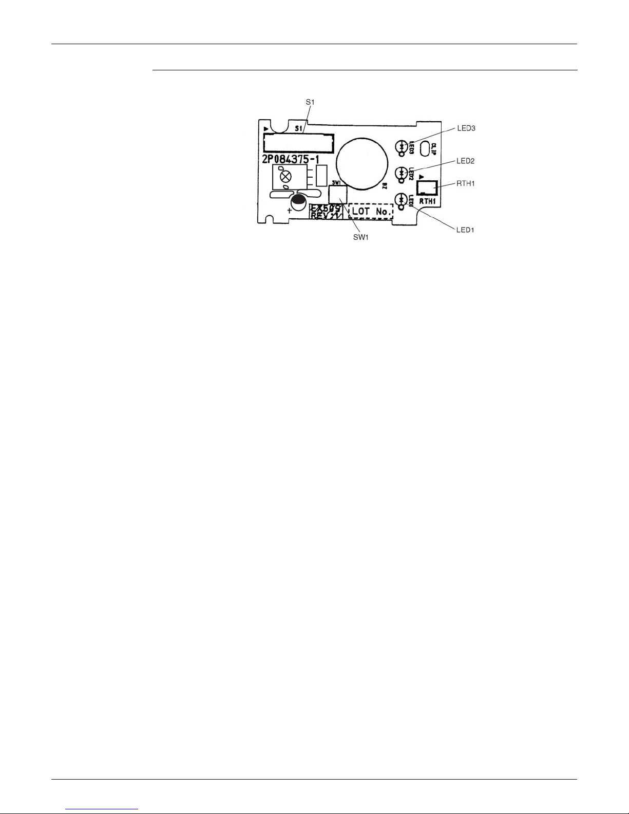
1.1.2 FDXS09/12DVJU
Connectors PCB (1) (Control PCB)
PCB (2) (Display PCB)
Note: Other designations
PCB (1) (Control PCB)
PCB (2) (Display PCB)
PCB Detail
PCB (1): Control PCB
1) S1 Connector for fan motor
2) S7 Connector for fan motor
3) S21 Connector for centralized control
4) S26 Connector for display PCB
5) S32 Connector for room temp/heat exchanger thermistor
1) S1 Connector for control PCB
1) V1 Varistor
2) JA Address setting jumper
JB Fan speed setting when compressor is OFF on thermostat.
JC Power failure recovery function.
∗ Refer to page 229 for more detail
3) LED A LED for service monitor (green)
4) FU1 Fuse (3.15A)
1) SW1 Forced operation ON/OFF switch
2) LED1 LED for operation (Green)
3) LED2 LED for timer (Yellow)
4) LED3 LED for HOME LEAVE Operations (Red)
5) RTH1 Room temperature thermistor
S1
V1
S7
S26
S32JCJBJA
S21
2P131149
LED A
Fu1
SiUS12-814 Printed Circuit Board Connector Wiring Diagram
Printed Circuit Board Connector Wiring Diagram 17
PCB Detail PCB (2): Display PCB
C1
C3
C2
WLU
PbF
2P084375
 Loading...