

Daikin FDXM25F3V1B, FDXM35F3V1B, FDXM50F3V1B, FDXM60F3V1B, FDXM25F3V1B9 Installer reference guide
...
Installer reference guide
Split system air conditioners
FDXM25F3V1B
FDXM35F3V1B
FDXM50F3V1B
FDXM60F3V1B
FDXM25F3V1B9
FDXM35F3V1B9
FDXM50F3V1B9
FDXM60F3V1B9
Installer reference guide
Split system air conditioners
English
Table of Contents
Table of Contents
1 General safety precautions 2
1.1 About the documentation .......................................................... 2
1.1.1 Meaning of warnings and symbols.............................. 2
1.2 For the installer.......................................................................... 3
1.2.1 General ....................................................................... 3
1.2.2 Installation site ............................................................ 3
1.2.3 Refrigerant .................................................................. 5
1.2.4 Brine............................................................................ 5
1.2.5 Water .......................................................................... 5
1.2.6 Electrical ..................................................................... 6
2 About the documentation 6
2.1 About this document.................................................................. 6
2.2 Installer reference guide at a glance ......................................... 7
3 About the box 7
3.1 Overview: About the box ........................................................... 7
3.2 Indoor unit ................................................................................. 7
3.2.1 To unpack and handle the unit.................................... 7
3.2.2 To remove the accessories from the indoor unit......... 7
4 About the units and options 7
4.1 Overview: About the units and options...................................... 7
4.2 System layout............................................................................ 8
4.3 Combining units and options ..................................................... 8
4.3.1 Possible options for the indoor unit............................. 8
5 Preparation 8
5.1 Overview: Preparation............................................................... 8
5.2 Preparing the installation site .................................................... 8
5.2.1 Installation site requirements of the indoor unit .......... 8
5.3 Preparing refrigerant piping....................................................... 9
5.3.1 Refrigerant piping requirements.................................. 9
5.3.2 Refrigerant piping insulation ....................................... 9
5.4 Preparing electrical wiring ......................................................... 9
5.4.1 About preparing electrical wiring................................. 9
6 Installation 10
6.1 Overview: Installation ................................................................ 10
6.2 Mounting the indoor unit............................................................ 10
6.2.1 Precautions when mounting the indoor unit................ 10
6.2.2 Guidelines when installing the indoor unit................... 10
6.2.3 Guidelines when installing the ducting........................ 11
6.2.4 Guidelines when installing the drain piping................. 11
6.3 Connecting the refrigerant piping .............................................. 12
6.3.1 About connecting the refrigerant piping ...................... 12
6.3.2 Precautions when connecting the refrigerant piping... 12
6.3.3 Guidelines when connecting the refrigerant piping..... 13
6.3.4 Pipe bending guidelines.............................................. 13
6.3.5 To flare the pipe end................................................... 13
6.3.6 To connect the refrigerant piping to the indoor unit .... 13
6.3.7 To check for leaks....................................................... 14
6.4 Connecting the electrical wiring................................................. 14
6.4.1 About connecting the electrical wiring......................... 14
6.4.2 Precautions when connecting the electrical wiring ..... 14
6.4.3 Guidelines when connecting the electrical wiring ....... 14
6.4.4 To connect the electrical wiring on the indoor unit...... 15
6.4.5 Specifications of standard wiring components............ 15
7 Configuration 15
7.1 Field settings ............................................................................. 15
8 Commissioning 16
8.1 Checklist before commissioning................................................ 16
8.2 To perform a test run................................................................. 16
8.3 Error codes when performing a test run .................................... 17
9 Hand-over to the user 17
10 Disposal 17
11 Technical data 17
11.1 Wiring diagram ........................................................................... 18
12 Glossary 18
1 General safety precautions
1.1 About the documentation
▪ The original documentation is written in English. All other
languages are translations.
▪ The precautions described in this document cover very important
topics, follow them carefully.
▪ The installation of the system, and all activities described in the
installation manual and the installer reference guide MUST be
performed by an authorised installer.
1.1.1 Meaning of warnings and symbols
DANGER
Indicates a situation that results in death or serious injury.
DANGER: RISK OF ELECTROCUTION
Indicates a situation that could result in electrocution.
DANGER: RISK OF BURNING
Indicates a situation that could result in burning because of
extreme hot or cold temperatures.
DANGER: RISK OF EXPLOSION
Indicates a situation that could result in explosion.
WARNING
Indicates a situation that could result in death or serious
injury.
WARNING: FLAMMABLE MATERIAL
CAUTION
Indicates a situation that could result in minor or moderate
injury.
NOTICE
Indicates a situation that could result in equipment or
property damage.
INFORMATION
Indicates useful tips or additional information.
Symbol Explanation
Before installation, read the installation and
operation manual, and the wiring instruction sheet.
Before performing maintenance and service tasks,
read the service manual.
For more information, see the installer and user
reference guide.
Installer reference guide
2
FDXM25~60F3V1B(9)
Split system air conditioners
4P550955-1 – 2018.07
1 General safety precautions
1.2 For the installer
1.2.1 General
If you are NOT sure how to install or operate the unit, contact your
dealer.
NOTICE
Improper installation or attachment of equipment or
accessories could result in electric shock, short-circuit,
leaks, fire or other damage to the equipment. Only use
accessories, optional equipment and spare parts made or
approved by Daikin.
WARNING
Make sure installation, testing and applied materials
comply with applicable legislation (on top of the
instructions described in the Daikin documentation).
CAUTION
Wear adequate personal protective equipment (protective
gloves, safety glasses,…) when installing, maintaining or
servicing the system.
WARNING
Tear apart and throw away plastic packaging bags so that
nobody, especially children, can play with them. Possible
risk: suffocation.
DANGER: RISK OF BURNING
▪ Do NOT touch the refrigerant piping, water piping or
internal parts during and immediately after operation. It
could be too hot or too cold. Give it time to return to
normal temperature. If you must touch it, wear
protective gloves.
▪ Do NOT touch any accidental leaking refrigerant.
WARNING
Provide adequate measures to prevent that the unit can be
used as a shelter by small animals. Small animals that
make contact with electrical parts can cause malfunctions,
smoke or fire.
1.2.2 Installation site
▪ Provide sufficient space around the unit for servicing and air
circulation.
▪ Make sure the installation site withstands the unit's weight and
vibration.
▪ Make sure the area is well ventilated. Do NOT block any
ventilation openings.
▪ Make sure the unit is level.
Do NOT install the unit in the following places:
▪ In potentially explosive atmospheres.
▪ In places where there is machinery that emits electromagnetic
waves. Electromagnetic waves may disturb the control system,
and cause malfunction of the equipment.
▪ In places where there is a risk of fire due to the leakage of
flammable gases (example: thinner or gasoline), carbon fibre,
ignitable dust.
▪ In places where corrosive gas (example: sulphurous acid gas) is
produced. Corrosion of copper pipes or soldered parts may cause
the refrigerant to leak.
Instructions for equipment using R32 refrigerant
If applicable.
WARNING
▪ Do NOT pierce or burn.
▪ Do NOT use means to accelerate the defrosting
process or to clean the equipment, other than those
recommended by the manufacturer.
▪ Be aware that R32 refrigerant does NOT contain an
odour.
WARNING
The appliance shall be stored so as to prevent mechanical
damage and in a well-ventilated room without continuously
operating ignition sources (example: open flames, an
operating gas appliance or an operating electric heater)
and have a room size as specified below.
CAUTION
Do NOT touch the air inlet or aluminium fins of the unit.
NOTICE
▪ Do NOT place any objects or equipment on top of the
unit.
▪ Do NOT sit, climb or stand on the unit.
NOTICE
Works executed on the outdoor unit are best done under
dry weather conditions to avoid water ingress.
In accordance with the applicable legislation, it might be necessary
to provide a logbook with the product containing at least: information
on maintenance, repair work, results of tests, stand-by periods,…
Also, at least, following information MUST be provided at an
accessible place at the product:
▪ Instructions for shutting down the system in case of an emergency
▪ Name and address of fire department, police and hospital
▪ Name, address and day and night telephone numbers for
obtaining service
In Europe, EN378 provides the necessary guidance for this logbook.
FDXM25~60F3V1B(9)
Split system air conditioners
4P550955-1 – 2018.07
NOTICE
▪ Do NOT re-use joints which have been used already.
▪ Joints made in installation between parts of refrigerant
system shall be accessible for maintenance purposes.
WARNING
Make sure installation, servicing, maintenance and repair
comply with instructions from Daikin and with applicable
legislation (for example national gas regulation) and are
executed only by authorised persons.
Installation space requirements
NOTICE
▪ Pipework shall be protected from physical damage.
▪ Installation of pipework shall be kept to a minimum.
Installer reference guide
3
1 General safety precautions
Contains fluorinated greenhouse gases
2
1
1
1
2
2
kg
tCO2eq
1000
GWP × kg
=
=
+
kg
=
kg
=
GWP: xxx
R32
0
10
20
30
40
50
60
70
80
90
100
110
120
130
140
150
160
170
180
190
200
210
220
230
240
250
260
270
280
290
300
310
320
330
340
350
360
370
380
390
400
410
420
430
440
450
460
470
480
490
500
510
520
530
540
550
1.822.2
2.4
2.6
2.833.2
3.4
3.6
3.844.2
4.4
4.6
4.855.2
5.4
5.6
5.866.2
6.4
6.6
6.877.2
7.4
7.6
7.8
1.843 7.956
8.0
A
min
(m2)
Floor-standing unit
(c)
Wall-mounted unit
(b)
Ceiling-mounted unit
(a)
m (kg)
Ceiling-mounted
unit
(a)
4.6 13.4
4.6 180
4.8 14.6
4.8 196
5.0 15.8
5.0 213
≤1.842 —
5.2 17.1
≤1.842 —
5.2 230
1.843 3.64
5.4 18.5
1.843 28.9
5.4 248
2.0 3.95
5.6 19.9
2.0 34.0
5.6 267
2.2 4.34
5.8 21.3
2.2 41.2
5.8 286
2.4 4.74
6.0 22.8
2.4 49.0
6.0 306
2.6 5.13
6.2 24.3
2.6 57.5
6.2 327
2.8 5.53
6.4 25.9
2.8 66.7
6.4 349
3.0 5.92
6.6 27.6
3.0 76.6
6.6 371
3.2 6.48
6.8 29.3
3.2 87.2
6.8 394
3.4 7.32
7.0 31.0
3.4 98.4
7.0 417
3.6 8.20
7.2 32.8
3.6 110
7.2 441
3.8 9.14
7.4 34.7
3.8 123
7.4 466
4.0 10.1
7.6 36.6
4.0 136
7.6 492
4.2 11.2
7.8 38.5
4.2 150
7.8 518
4.4 12.3
7.956 40.1
4.4 165
7.956 539
m (kg)
A
min
(m2)
4.6 20.0
4.8 21.8
5.0 23.6
≤1.842 —
5.2 25.6
1.843 4.45
5.4 27.6
2.0 4.83
5.6 29.7
2.2 5.31
5.8 31.8
2.4 5.79
6.0 34.0
2.6 6.39
6.2 36.4
2.8 7.41
6.4 38.7
3.0 8.51
6.6 41.2
3.2 9.68
6.8 43.7
3.4 10.9
7.0 46.3
3.6 12.3
7.2 49.0
3.8 13.7
7.4 51.8
4.0 15.1
7.6 54.6
4.2 16.7
7.8 57.5
4.4 18.3
7.956 59.9
Wall-mounted
unit
(b)
m (kg)
A
min
(m2)
Floor-standing
unit
(c)
m (kg)
A
min
(m2)
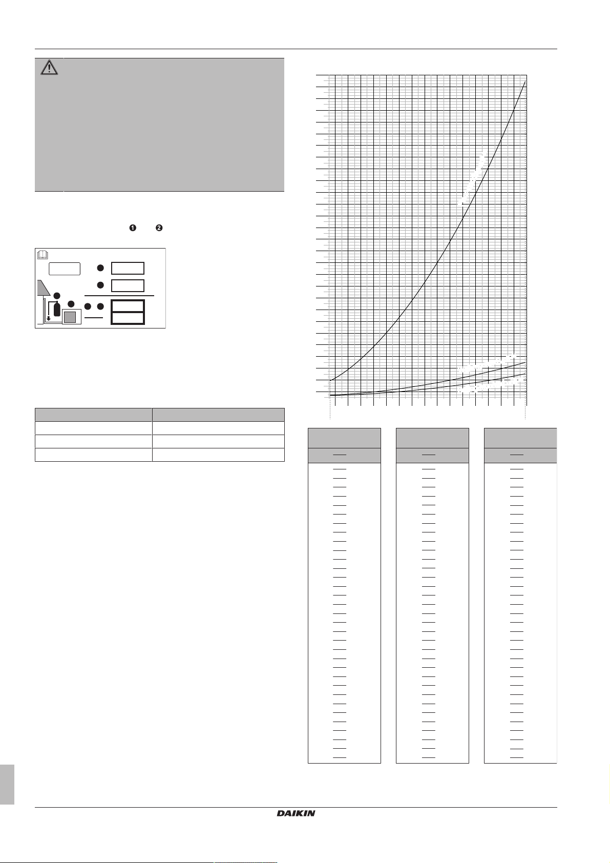
WARNING
If appliances contain R32 refrigerant, the floor area of the
room in which the appliances are installed, operated and
stored MUST be larger than the minimum floor area
defined in table below A (m2). This applies to:
▪ Indoor units without a refrigerant leakage sensor; in
case of indoor units with refrigerant leakage sensor,
consult the installation manual
▪ Outdoor units installed or stored indoors (e.g. winter
garden, garage, machinery room)
▪ Pipework in unventilated spaces
To determine the minimum floor area
1 Determine the total refrigerant charge in the system (= factory
refrigerant charge + additional refrigerant amount
charged).
2 Determine which graph or table to use.
▪ For indoor units: Is the unit ceiling-mounted, wall-mounted or
floor-standing?
▪ For outdoor units installed or stored indoors, and field piping
in unventilated spaces, this depends on the installation
height:
If the installation height is… Then use the graph or table for…
<1.8m Floor-standing units
1.8≤x<2.2m Wall-mounted units
≥2.2m Ceiling-mounted units
3 Use the graph or table to determine the minimum floor area.
Installer reference guide
4
m Total refrigerant charge in the system
A
Minimum floor area
min
(a) Ceiling-mounted unit (= Ceiling-mounted unit)
(b) Wall-mounted unit (= Wall-mounted unit)
FDXM25~60F3V1B(9)
Split system air conditioners
4P550955-1 – 2018.07
1 General safety precautions
(c) Floor-standing unit (= Floor-standing unit)
1.2.3 Refrigerant
If applicable. See the installation manual or installer reference guide
of your application for more information.
NOTICE
Make sure refrigerant piping installation complies with
applicable legislation. In Europe, EN378 is the applicable
standard.
NOTICE
Make sure the field piping and connections are NOT
subjected to stress.
WARNING
During tests, NEVER pressurize the product with a
pressure higher than the maximum allowable pressure (as
indicated on the nameplate of the unit).
WARNING
Take sufficient precautions in case of refrigerant leakage. If
refrigerant gas leaks, ventilate the area immediately.
Possible risks:
▪ Excessive refrigerant concentrations in a closed room
can lead to oxygen deficiency.
▪ Toxic gas may be produced if refrigerant gas comes
into contact with fire.
DANGER: RISK OF EXPLOSION
Pump down – Refrigerant leakage. If you want to pump
down the system, and there is a leak in the refrigerant
circuit:
▪ Do NOT use the unit's automatic pump down function,
with which you can collect all refrigerant from the
system into the outdoor unit. Possible consequence:
Self-combustion and explosion of the compressor
because of air going into the operating compressor.
▪ Use a separate recovery system so that the unit's
compressor does NOT have to operate.
WARNING
ALWAYS recover the refrigerant. Do NOT release them
directly into the environment. Use a vacuum pump to
evacuate the installation.
NOTICE
After all the piping has been connected, make sure there is
no gas leak. Use nitrogen to perform a gas leak detection.
NOTICE
▪ To avoid compressor breakdown, do NOT charge more
than the specified amount of refrigerant.
▪ When the refrigerant system is to be opened,
refrigerant MUST be treated according to the applicable
legislation.
WARNING
Make sure there is no oxygen in the system. Refrigerant
may only be charged after performing the leak test and the
vacuum drying.
▪ In case re-charge is required, refer to the nameplate of the unit. It
states the type of refrigerant and necessary amount.
▪ The unit is factory charged with refrigerant and depending on pipe
sizes and pipe lengths some systems require additional charging
of refrigerant.
▪ Only use tools exclusively for the refrigerant type used in the
system, this to ensure pressure resistance and prevent foreign
materials from entering into the system.
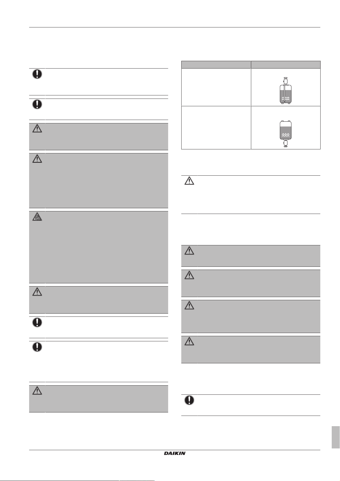
▪ Charge the liquid refrigerant as follows:
If Then
A siphon tube is present
(i.e., the cylinder is marked with
"Liquid filling siphon attached")
A siphon tube is NOT present Charge with the cylinder upside
▪ Open refrigerant cylinders slowly.
▪ Charge the refrigerant in liquid form. Adding it in gas form may
prevent normal operation.
CAUTION
When the refrigerant charging procedure is done or when
pausing, close the valve of the refrigerant tank
immediately. If the valve is NOT closed immediately,
remaining pressure might charge additional refrigerant.
Possible consequence: Incorrect refrigerant amount.
Charge with the cylinder upright.
down.
1.2.4 Brine
If applicable. See the installation manual or installer reference guide
of your application for more information.
WARNING
The selection of the brine MUST be in accordance with the
applicable legislation.
WARNING
Take sufficient precautions in case of brine leakage. If
brine leaks, ventilate the area immediately and contact
your local dealer.
WARNING
The ambient temperature inside the unit can get much
higher than that of the room, e.g. 70°C. In case of a brine
leak, hot parts inside the unit can create a hazardous
situation.
WARNING
The use and installation of the application MUST comply
with the safety and environmental precautions specified in
the applicable legislation.
1.2.5 Water
If applicable. See the installation manual or installer reference guide
of your application for more information.
NOTICE
Make sure water quality complies with EU directive
98/83EC.
FDXM25~60F3V1B(9)
Split system air conditioners
4P550955-1 – 2018.07
Installer reference guide
5
2 About the documentation
1.2.6 Electrical
DANGER: RISK OF ELECTROCUTION
▪ Turn OFF all power supply before removing the
switch box cover, connecting electrical wiring or
touching electrical parts.
▪ Disconnect the power supply for more than 1minute,
and measure the voltage at the terminals of main circuit
capacitors or electrical components before servicing.
The voltage MUST be less than 50 V DC before you
can touch electrical components. For the location of the
terminals, see the wiring diagram.
▪ Do NOT touch electrical components with wet hands.
▪ Do NOT leave the unit unattended when the service
cover is removed.
WARNING
If NOT factory installed, a main switch or other means for
disconnection, having a contact separation in all poles
providing full disconnection under overvoltage category III
condition, MUST be installed in the fixed wiring.
WARNING
▪ ONLY use copper wires.
▪ Make sure the field wiring complies with the applicable
legislation.
▪ All field wiring MUST be performed in accordance with
the wiring diagram supplied with the product.
▪ NEVER squeeze bundled cables and make sure they
do NOT come in contact with the piping and sharp
edges. Make sure no external pressure is applied to the
terminal connections.
▪ Make sure to install earth wiring. Do NOT earth the unit
to a utility pipe, surge absorber, or telephone earth.
Incomplete earth may cause electrical shock.
▪ Make sure to use a dedicated power circuit. NEVER
use a power supply shared by another appliance.
▪ Make sure to install the required fuses or circuit
breakers.
▪ Make sure to install an earth leakage protector. Failure
to do so may cause electric shock or fire.
▪ When installing the earth leakage protector, make sure
it is compatible with the inverter (resistant to high
frequency electric noise) to avoid unnecessary opening
of the earth leakage protector.
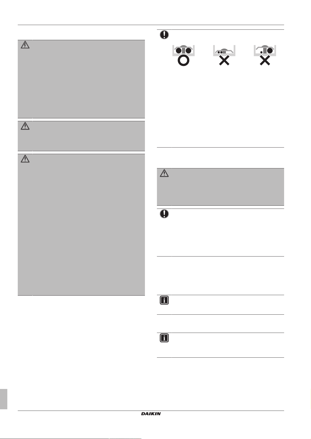
NOTICE
Precautions when laying power wiring:
▪ Do NOT connect wiring of different thicknesses to the
power terminal block (slack in the power wiring may
cause abnormal heat).
▪ When connecting wiring which is the same thickness,
do as shown in the figure above.
▪ For wiring, use the designated power wire and connect
firmly, then secure to prevent outside pressure being
exerted on the terminal board.
▪ Use an appropriate screwdriver for tightening the
terminal screws. A screwdriver with a small head will
damage the head and make proper tightening
impossible.
▪ Over-tightening the terminal screws may break them.
Install power cables at least 1 metre away from televisions or radios
to prevent interference. Depending on the radio waves, a distance of
1metre may not be sufficient.
WARNING
▪ After finishing the electrical work, confirm that each
electrical component and terminal inside the electrical
components box is connected securely.
▪ Make sure all covers are closed before starting up the
unit.
NOTICE
Only applicable if the power supply is three‑phase, and the
compressor has an ON/OFF starting method.
If there exists the possibility of reversed phase after a
momentary black out and the power goes on and off while
the product is operating, attach a reversed phase
protection circuit locally. Running the product in reversed
phase can break the compressor and other parts.
2 About the documentation
2.1 About this document
INFORMATION
Make sure that the user has the printed documentation and
ask him/her to keep it for future reference.
Installer reference guide
6
Target audience
Authorised installers
INFORMATION
This appliance is intended to be used by expert or trained
users in shops, in light industry, and on farms, or for
commercial and household use by lay persons.
Documentation set
This document is part of a documentation set. The complete set
consists of:
▪ General safety precautions:
▪ Safety instructions that you MUST read before installing
▪ Format: Paper (in the box of the indoor unit)
FDXM25~60F3V1B(9)
Split system air conditioners
4P550955-1 – 2018.07

3 About the box
24×8×1× 1×
2×
1×
1×
1×
2×
1×
ed
ba
1×
c
f g
h
i j k l
6×
m
4×
n
1×
▪ Indoor unit installation manual:
▪ Installation instructions
▪ Format: Paper (in the box of the indoor unit)
▪ Installer reference guide:
▪ Preparation of the installation, good practices, reference data,…
▪ Format: Digital files on http://www.daikineurope.com/support-
and-manuals/product-information/
Latest revisions of the supplied documentation may be available on
the regional Daikin website or via your dealer.
The original documentation is written in English. All other languages
are translations.
Technical engineering data
▪ A subset of the latest technical data is available on the regional
Daikin website (publicly accessible).
▪ The full set of latest technical data is available on the Daikin
extranet (authentication required).
2.2 Installer reference guide at a glance
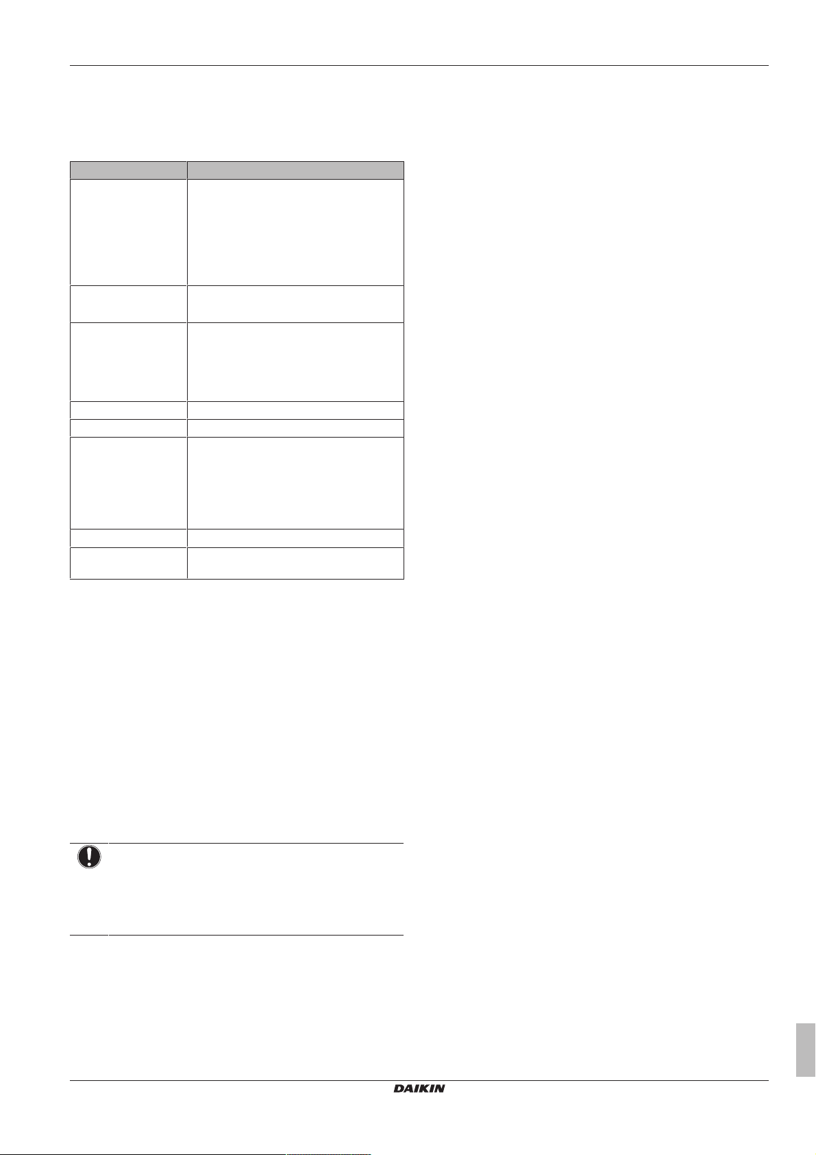
Chapter Description
General safety
precautions
About the documentation What documentation exists for the
About the box How to unpack the units and remove
About the units and
options
Preparation What to do and know before going
Installation What to do and know to install the
Configuration What to do and know to configure the
Commissioning What to do and know to commission the
Hand‑over to the user What to give and explain to the user
Disposal How to dispose of the system
Technical data Specifications of the system
Glossary Definition of terms
Safety instructions that you MUST read
before installing
installer
their accessories
▪ System layout
▪ Combining units and options
on‑site
system
system after it is installed
system after it is configured
3.2 Indoor unit
WARNING: FLAMMABLE MATERIAL
The R32 refrigerant (if applicable) in this unit is mildly
flammable. Refer to the outdoor unit specifications for the
type of refrigerant to be used.
3.2.1 To unpack and handle the unit
Use a sling of soft material or protective plates together with a rope
when lifting the unit. This to avoid damage or scratches to the unit.
Lift the unit by holding on to the hanger brackets without exerting
any pressure on other parts, especially on refrigerant piping, drain
piping and other resin parts.
3.2.2 To remove the accessories from the indoor unit
a Installation manual
b Operation manual
c General safety precautions
d Washers for hanger bracket
e Screws for duct flanges
f Metal clamp
g Sealing pads: small and large
h Drain hose
i Sealing material
j Insulation piece: Small (liquid pipe)
k Insulation piece: Large (gas pipe)
l Tie wraps
m Washer fixing plate
n Air filter
4 About the units and options
3 About the box
4.1 Overview: About the units and
3.1 Overview: About the box
Keep the following in mind:
▪ At delivery, the unit MUST be checked for damage. Any damage
MUST be reported immediately to the carrier's claims agent.
▪ Bring the packed unit as close as possible to its final installation
position to prevent damage during transport.
▪ Prepare the path along which you want to bring the unit inside in
advance.
FDXM25~60F3V1B(9)
Split system air conditioners
4P550955-1 – 2018.07
This chapter contains information about:
▪ Combining outdoor and indoor units
▪ Combining the indoor unit with options
options
Installer reference guide
7

5 Preparation
b
c
a
e
d
f
g
h
4.2 System layout
a Indoor unit
b Outdoor unit
c User interface
d Suction air
e Discharge air
f Refrigerant piping + interconnection cable
g Drain pipe
h Earth wiring
4.3 Combining units and options
4.3.1 Possible options for the indoor unit
Make sure you have the following mandatory options:
▪ User interface: Wired or wireless (refer to catalogues and
technical literature for selecting a suitable user interface)
5 Preparation
5.1 Overview: Preparation
This chapter describes what you have to do and know before going
on-site.
It contains information about:
▪ Preparing the installation site
▪ Preparing the refrigerant piping
▪ Preparing the electrical wiring
5.2 Preparing the installation site
▪ Provide sufficient space around the unit for servicing and air
circulation.
▪ Choose the installation location with sufficient space for carrying
the unit in and out of the site.
WARNING
Do NOT install the air conditioner at any place where
flammable gas may leak out. If the gas leaks out and stays
around the air conditioner, a fire may break out.
5.2.1 Installation site requirements of the indoor unit
INFORMATION
Also read the following requirements:
▪ General installation site requirements. See the
"General safety precautions" chapter.
▪ Refrigerant piping requirements (length, height
difference). See further in this "Preparation" chapter.
INFORMATION
The sound pressure level is less than 70dBA.
NOTICE
The equipment described in this manual may cause
electronic noise generated from radio-frequency energy.
The equipment complies to specifications that are
designed to provide reasonable protection against such
interference. However, there is no guarantee that
interference will not occur in a particular installation.
It is therefore recommended to install the equipment and
electric wires keeping proper distances away from stereo
equipment, personal computers, etc.
Install power cables at least 1 metre away from televisions or radios
to prevent interference. Depending on the radio waves, a distance of
1metre may not be sufficient.
▪ Fluorescent lights. When installing a wireless user interface in a
room with fluorescent lights, mind the following to avoid
interference:
▪ Install the wireless user interface as close as possible to the
indoor unit.
▪ Install the indoor unit as far as possible from the fluorescent
lights.
▪ Signal receiver with built-in temperature sensor must be
installed on a location:
▪ near the intake vent (when installation near the intake vent is
not possible, install 1.5m above the floor)
▪ which is not exposed to cold or hot air.
▪ where signal may not be blocked by curtain, etc.
▪ Take care that in the event of a water leak, water cannot cause
any damage to the installation space and surroundings.
▪ Choose a location where the hot/cold air discharged from the unit
or the operation noise, will NOT disturb anyone.
WARNING
Do NOT place objects below the indoor and/or outdoor unit
that may get wet. Otherwise condensation on the main unit
or refrigerant pipes, air filter dirt or drain blockage may
cause dripping, and objects under the unit may get dirty or
damaged.
▪ Air flow. Make sure nothing blocks the air flow.
▪ Drainage. Make sure condensation water can be evacuated
properly.
▪ Ceiling insulation. When conditions in the ceiling exceed 30°C
and a relative humidity of 80%, or when fresh air is inducted into
the ceiling, then additional insulation is required (minimum 10mm
thickness, polyethylene foam).
Installer reference guide
8
FDXM25~60F3V1B(9)
Split system air conditioners
4P550955-1 – 2018.07
5 Preparation
200
e:
≥240
A
≥20
≥300
b
c
d
a
(mm)
≥400
t
Ø
ØiØ
i
t
ØpØ
p
▪ Protective guards. Make sure to install protective guards on the
suction and discharge side to prevent somebody from touching
the fan blades or heat exchanger.
Do NOT install the unit in the following places:
▪ In places where a mineral oil mist, spray or vapour may be
present in the atmosphere. Plastic parts may deteriorate and fall
off or cause water leakage.
It is NOT recommended to install the unit in the following places
because it may shorten the life of the unit:
▪ Where the voltage fluctuates a lot
▪ In vehicles or vessels
▪ Where acidic or alkaline vapour is present
▪ Use suspension bolts for installation.
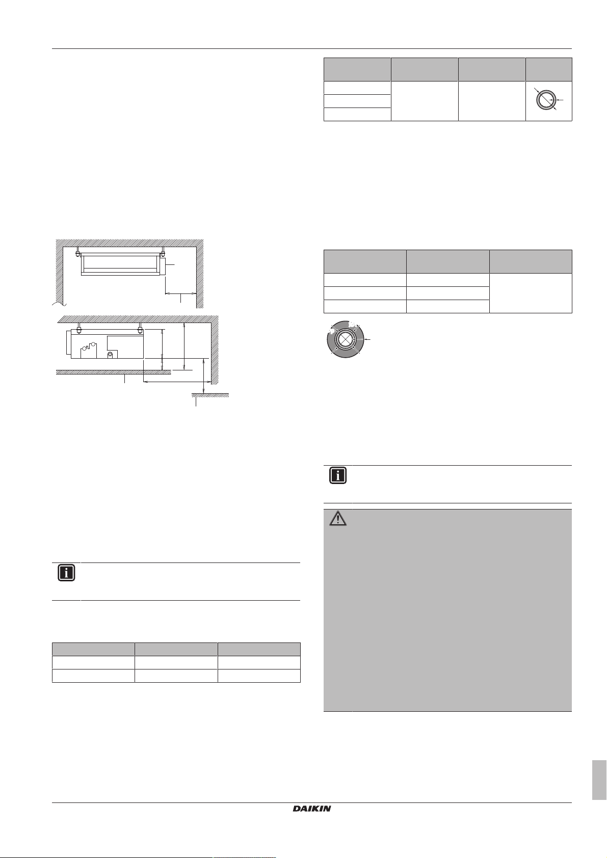
▪ Spacing. Mind the following requirements:
Outer diameter
Temper grade Thickness (t)
(a)
(Ø)
6.4mm (1/4") Annealed (O) ≥0.8mm
9.5mm (3/8")
12.7mm (1/2")
(a) Depending on the applicable legislation and the unit's
maximum working pressure (see "PS High" on the unit
name plate), larger piping thickness might be required.
5.3.2 Refrigerant piping insulation
▪ Use polyethylene foam as insulation material:
▪ with a heat transfer rate between 0.041 and 0.052W/mK (0.035
and 0.045kcal/mh°C)
▪ with a heat resistance of at least 120°C
▪ Insulation thickness
Pipe outer diameter
(Øp)
6.4mm (1/4") 8~10mm ≥10mm
9.5mm (3/8") 12~15mm
12.7mm (1/2") 14~16mm
Insulation inner
diameter (Øi)
Insulation thickness
(t)
A Minimum distance to the floor:
2.7m to avoid accidental touching.
2.5m in case the fan is covered (e.g. false ceiling, grille,
…)
a Control box
b Maintenance space
c Ceiling
d Floor surface
e Select the dimension to ensure downward slope of at least
1/100
5.3 Preparing refrigerant piping
5.3.1 Refrigerant piping requirements
INFORMATION
Also read the precautions and requirements in the
"General safety precautions" chapter.
Refrigerant piping diameter
Use the same diameters as the connections on the outdoor units:
Class L1 liquid piping L1 gas piping
25+35 Ø6.4 Ø9.5
50+60 Ø6.4 Ø12.7
Refrigerant piping material
▪ Piping material: Phosphoric acid deoxidised seamless copper.
▪ Piping temper grade and thickness:
If the temperature is higher than 30°C and the humidity is higher
than RH 80%, the thickness of the insulation materials should be at
least 20 mm to prevent condensation on the surface of the
insulation.
5.4 Preparing electrical wiring
5.4.1 About preparing electrical wiring
INFORMATION
Also read the precautions and requirements in the
"General safety precautions" chapter.
WARNING
▪ If the power supply has a missing or wrong N-phase,
equipment might break down.
▪ Establish proper earthing. Do NOT earth the unit to a
utility pipe, surge absorber, or telephone earth.
Incomplete earthing may cause electrical shock.
▪ Install the required fuses or circuit breakers.
▪ Secure the electrical wiring with cable ties so that the
cables do NOT come in contact with sharp edges or
piping, particularly on the high-pressure side.
▪ Do NOT use taped wires, stranded conductor wires,
extension cords, or connections from a star system.
They can cause overheating, electrical shock or fire.
▪ Do NOT install a phase advancing capacitor, because
this unit is equipped with an inverter. A phase
advancing capacitor will reduce performance and may
cause accidents.
Installer reference guide
9
FDXM25~60F3V1B(9)
Split system air conditioners
4P550955-1 – 2018.07
6 Installation
d
e
A
B
f
620
500
f
a1
b
b
a2
c
4×
b
a
c
e
d
WARNING
▪ All wiring MUST be performed by an authorised
electrician and MUST comply with the applicable
legislation.
▪ Make electrical connections to the fixed wiring.
▪ All components procured on-site and all electrical
construction MUST comply with the applicable
legislation.
WARNING
ALWAYS use multicore cable for power supply cables.
6 Installation
6.1 Overview: Installation
This chapter describes what you have to do and know on-site to
install the system.
Typical workflow
Installation typically consists of the following stages:
1 Mounting the outdoor unit.
2 Mounting the indoor unit.
3 Connecting the refrigerant piping.
4 Checking the refrigerant piping.
5 Charging refrigerant.
6 Connecting the electrical wiring.
7 Finishing the outdoor installation.
8 Finishing the indoor installation.
▪ Ceiling strength. Check whether the ceiling is strong enough to
support the weight of the unit. If there is a risk, reinforce the ceiling
before installing the unit.
▪ For existing ceilings, use anchors.
▪ For new ceilings, use sunken inserts, sunken anchors or other
field supplied parts.
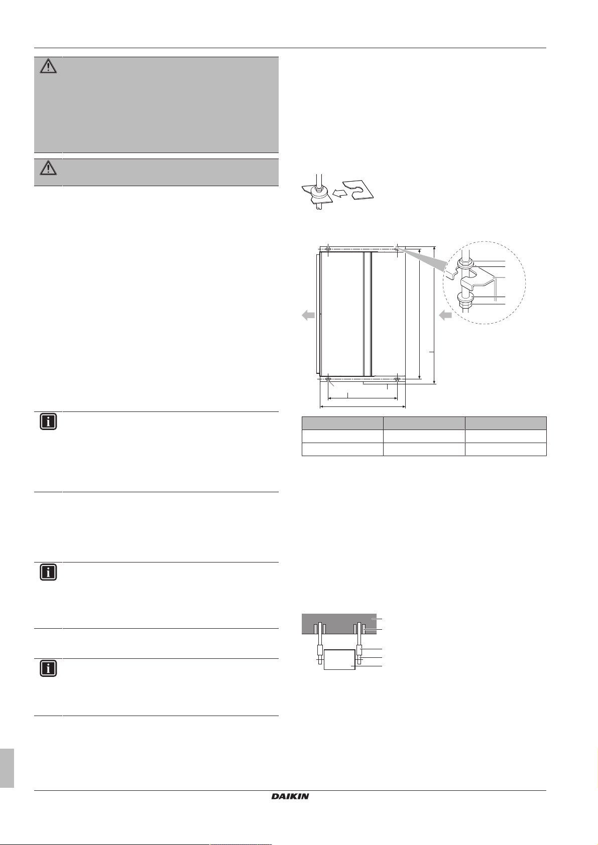
▪ Suspension bolts. Use W3/8 M10 suspension bolts for
installation. Attach the hanger bracket to the suspension bolt. Fix it
securely using a nut and washer from the upper and lower sides
of the hanger bracket.
▪ Ceiling opening size. Make sure the ceiling opening is within the
following limits:
INFORMATION
This chapter only describes installation instructions specific
to the indoor unit. For the other instructions, see:
▪ The installation manual of the outdoor unit
▪ The installation manual of the user interface
▪ The installation manual of the optional accessories
6.2 Mounting the indoor unit
6.2.1 Precautions when mounting the indoor unit
INFORMATION
Also read the precautions and requirements in the
following chapters:
▪ General safety precautions
▪ Preparation
6.2.2 Guidelines when installing the indoor unit
INFORMATION
Optional equipment. When installing optional equipment,
also read the installation manual of the optional equipment.
Depending on the field conditions, it might be easier to
install the optional equipment first.
Class A(mm) B(mm)
FDXM25+35 740 790
FDXM50+60 1140 1190
a1 Nut (field supply)
a2 Double nut (field supply)
b Washer (accessories)
c Hanger bracket
d Control box
e Suspension bolt pitch
f Overall dimension
▪ External static pressure. Refer to technical documentation to
ensure that the unit's external static pressure is not exceeded.
▪ Ceiling opening. (Ceiling with opening for installation)
1 Pass all pipes and wiring through the unit's piping and wiring
holes.
2 Make sure that the ceiling is level.
▪ Installation example:
a Anchor bolt
b Ceiling slab
c Long nut or turn-buckle
d Suspension bolt
e Indoor unit
▪ Install suction cover and air filter (accessory) In case of
bottom suction:
3 Remove the suction cover.
Installer reference guide
10
FDXM25~60F3V1B(9)
Split system air conditioners
4P550955-1 – 2018.07

c
a
b
4 Reattach the removed suction cover.
c
b
a
2
1
2
1
b
a
a b b a
eed d
c
a Air inlet
b Air outlet
c Suction cover
5 Attach the air filter (accessory) by pushing down the hooks (2
hooks for 25+35 type, 3 hooks for 50+60 type).
6 Installation
6.2.3 Guidelines when installing the ducting
WARNING
If the one or more rooms are connected with the unit via
duct system make sure:
▪ there are no operating ignition sources (example: open
flames, an operating gas appliance or an operating
electric heater) in case the floor area is less than A
specified in the General safety precautions;
▪ no auxiliary devices, which may be a potential ignition
source, are installed in the duct work (example: hot
surfaces with a temperature exceeding 700°C and
electric switching device);
▪ only auxiliary devices approved by manufacturer are
used in the duct work.
WARNING
Do NOT install operating ignition sources (example: open
flames, an operating gas appliance or an operating electric
heater) in the duct work.
The ducting is to be field supplied.
▪ Air inlet side. Attach the duct and intake-side flange (field
supply). For connecting the flange, use 7 accessory screws.
min
rear suction bottom suction
▪ Install the unit temporarily.
6 Attach the hanger bracket to the suspension bolt.
7 Fix the unit securely.
▪ Level. Make sure the unit is level at all four corners using a level
or a water-filled vinyl tube.
a Level
b Vinyl tube
8 Tighten the upper nut.
NOTICE
Do NOT install the unit tilted. Possible consequence: If
the unit is tilted against the direction of the condensate flow
(the drain piping side is raised), the float switch might
malfunction and cause water to drip.
a Connection screw (accessory)
b Flange (field supply)
c Main unit
d Insulation (field supply)
e Aluminium tape (field supply)
▪ Filter. Be sure to attach an air filter inside the air passage on the
intake side. Use an air filter with dust collecting efficiency ≥50%
(gravimetric method). The included filter is not used when the
intake duct is attached.
▪ Air outlet side. Connect the duct according to the inside
dimension of the outlet-side flange.
▪ Air leaks. Wind aluminium tape around the intake side flange and
duct connection. Make sure there are no air leaks at any other
connection.
▪ Insulation. Insulate the duct to prevent condensation from
forming. Use glass wool or polyethylene foam 25mm thick.
6.2.4 Guidelines when installing the drain piping
General guidelines
▪ Drain pump. For this "high lift type", the drainage sounds will be
reduced when the drain pump is installed in a higher location.
Recommended height is 300 mm.
▪ Pipe length. Keep drain piping as short as possible.
▪ Pipe size. Keep the pipe size equal to or greater than that of the
connecting pipe (vinyl pipe of 20 mm nominal diameter and
26mm outer diameter).
▪ Slope. Make sure the drain piping slopes down (at least 1/100) to
prevent air from being trapped in the piping. Use hanging bars as
shown.
FDXM25~60F3V1B(9)
Split system air conditioners
4P550955-1 – 2018.07
Installer reference guide
11

6 Installation
1~1.5 m
a
≤4 mm
A
A'
A-A'
A
A'
f
652
ce
4
ba
d
b
a
d
c
3
1
2~61
a
a
b
ed
a
b
c
a Hanging bar
O Allowed
X Not allowed
▪ Condensation. Take measures against condensation. Insulate
the complete drain piping in the building.
To connect the drain piping to the indoor unit
NOTICE
Incorrect connection of the drain hose might cause leaks,
and damage the installation space and surroundings.
1 Push the drain hose as far as possible over the drain pipe
connection.
2 Tighten the metal clamp until the screw head is less than 4mm
from the metal clamp part.
3 Check for water leaks (see "To check for water leaks" on
page12).
4 Install the insulation piece (drain pipe).
5 Wind the large sealing pad (= insulation) around the metal
clamp and drain hose, and fix it with cable ties.
6 Connect the drain piping to the drain hose.
▪ Set the plug and push it in using a Phillips screwdriver.
a Drain plug
b Phillips screwdriver
To check for water leaks
Gradually pour approximately 1 l of water in the drain pan, and
check for water leaks.
a Air outlet
b Portable pump
c Bucket
d Refrigerant pipes
e Drain outlet
a Drain pipe connection (attached to the unit)
b Drain hose (accessory)
c Metal clamp (accessory)
d Large sealing pad (accessory)
e Insulation piece (drain pipe) (accessory)
f Drain piping (field supply)
NOTICE
▪ Do NOT remove the drain pipe plug. Water might leak
out.
▪ Use the drain outlet only to discharge the water if the
drain pump is not used or before maintenance.
▪ Insert and remove the drain plug gently. Excessive
force may deform the drain socket of the drain pan.
Pull out the plug.
▪ Do NOT wiggle the plug up and down.
6.3 Connecting the refrigerant piping
6.3.1 About connecting the refrigerant piping
Before connecting the refrigerant piping
Make sure the outdoor and indoor unit are mounted.
Typical workflow
Connecting the refrigerant piping involves:
▪ Connecting the refrigerant piping to the outdoor unit
▪ Connecting the refrigerant piping to the indoor unit
▪ Insulating the refrigerant piping
▪ Keeping in mind the guidelines for:
▪ Pipe bending
▪ Flaring pipe ends
▪ Brazing
▪ Using the stop valves
6.3.2 Precautions when connecting the refrigerant piping
INFORMATION
Also read the precautions and requirements in the
following chapters:
▪ General safety precautions
▪ Preparation
DANGER: RISK OF BURNING
CAUTION
▪ Do NOT use mineral oil on flared part.
Push in the plug.
Installer reference guide
12
▪ NEVER install a drier to this unit to guarantee its
lifetime. The drying material may dissolve and damage
the system.
FDXM25~60F3V1B(9)
Split system air conditioners
4P550955-1 – 2018.07

6 Installation
a
b
c
d
R=0.4~0.8
45°
±2
90°
±2
A
a b
A
a b
c
NOTICE
Take the following precautions on refrigerant piping into
account:
▪ Avoid anything but the designated refrigerant to get
mixed into the refrigerant cycle (e.g. air).
▪ Only use R32 or R410A when adding refrigerant. Refer
to the outdoor unit specifications for the type of
refrigerant to be used.
▪ Only use installation tools (e.g. manifold gauge set) that
are exclusively used for R32 or R410A installations to
withstand the pressure and to prevent foreign materials
(e.g. mineral oils and moisture) from mixing into the
system.
▪ Install the piping so that the flare is NOT subjected to
mechanical stress.
▪ Protect the piping as described in the following table to
prevent dirt, liquid or dust from entering the piping.
▪ Use caution when passing copper tubes through walls
(see figure below).
Piping size
(mm)
Tightening
torque (N•m)
Flare
dimensions (A)
Flare shape
(mm)
(mm)
Ø6.4 15~17 8.7~9.1
Ø9.5 33~39 12.8~13.2
Ø12.7 50~60 16.2~16.6
6.3.4 Pipe bending guidelines
Use a pipe bender for bending. All pipe bends should be as gentle
as possible (bending radius should be 30~40mm or larger).
6.3.5 To flare the pipe end
CAUTION
▪ Incomplete flaring may cause refrigerant gas leakage.
▪ Do NOT re-use flares. Use new flares to prevent
refrigerant gas leakage.
▪ Use flare nuts that are included with the unit. Using
different flare nuts may cause refrigerant gas leakage.
1 Cut the pipe end with a pipe cutter.
2 Remove burrs with the cut surface facing down so that the
chips do NOT enter the pipe.
Unit Installation period Protection method
Outdoor unit >1month Pinch the pipe
<1month Pinch or tape the pipe
Indoor unit Regardless of the
period
INFORMATION
Do NOT open the refrigerant stop valve before checking
the refrigerant piping. When you need to charge additional
refrigerant it is recommended to open the refrigerant stop
valve after charging.
6.3.3 Guidelines when connecting the refrigerant piping
Take the following guidelines into account when connecting pipes:
▪ Coat the flare inner surface with ether oil or ester oil when
connecting a flare nut. Tighten 3 or 4 turns by hand, before
tightening firmly.
▪ ALWAYS use 2 wrenches together when loosening a flare nut.
▪ ALWAYS use a spanner and torque wrench together to tighten the
flare nut when connecting the piping. This to prevent nut cracking
and leaks.
a Cut exactly at right angles.
b Remove burrs.
3 Remove the flare nut from the stop valve and put the flare nut
on the pipe.
4 Flare the pipe. Set exactly at the position as shown in the
following figure.
Flare tool for
R410A or R32
(clutch type)
Conventional flare tool
Clutch type
(Ridgid-type)
Wing nut type
(Imperial-type)
A 0~0.5mm 1.0~1.5mm 1.5~2.0mm
5 Check that the flaring is properly made.
a Flare’s inner surface MUST be flawless.
b The pipe end MUST be evenly flared in a perfect circle.
c Make sure the flare nut is fitted.
6.3.6 To connect the refrigerant piping to the indoor unit
a Torque wrench
b Spanner
c Piping union
d Flare nut
FDXM25~60F3V1B(9)
Split system air conditioners
4P550955-1 – 2018.07
CAUTION
Install refrigerating pipe or components in a position where
they are unlikely to be exposed to any substance which
may corrode refrigerant containing components, unless the
components are constructed of materials which are
inherently resistant to being corroded or are suitably
protected against being so corroded.
Installer reference guide
13

6 Installation
A B
a dc e fb b
a dc e fb b
2
4
3
g
1
23
4
g
AB
1
b a
c b
c
aa
A
AA´
A´
WARNING: FLAMMABLE MATERIAL
The R32 refrigerant (if applicable) in this unit is mildly
flammable. Refer to the outdoor unit specifications for the
type of refrigerant to be used.
▪ Pipe length. Keep refrigerant piping as short as possible.
▪ Flare connections. Connect refrigerant piping to the unit using
flare connections.
▪ Insulation. Insulate the refrigerant piping on the indoor unit as
follows:
A Gas piping
B Liquid piping
a Insulation material (field supply)
b Cable tie (accessory)
c Insulation pieces: Large (gas pipe), small (liquid pipe)
(accessories)
d Flare nut (attached to the unit)
e Refrigerant pipe connection (attached to the unit)
f Unit
g Sealing pads: Medium 1 (gas pipe), medium 2 (liquid pipe)
(accessories)
1 Turn up the seams of the insulation pieces.
2 Attach to the base of the unit.
3 Tighten the cable ties on the insulation pieces.
4 Wrap the sealing pad from the base of the unit to the top of
the flare nut.
NOTICE
Make sure to insulate all refrigerant piping. Any exposed
piping might cause condensation.
6.3.7 To check for leaks
NOTICE
Do NOT exceed the unit's maximum working pressure (see
"PS High" on the unit name plate).
6.4 Connecting the electrical wiring
6.4.1 About connecting the electrical wiring
Typical workflow
Connecting the electrical wiring typically consists of the following
stages:
1 Making sure the power supply system complies with the
electrical specifications of the units.
2 Connecting the electrical wiring to the outdoor unit.
3 Connecting the electrical wiring to the indoor unit.
4 Connecting the main power supply.
6.4.2 Precautions when connecting the electrical wiring
INFORMATION
Also read the precautions and requirements in the
following chapters:
▪ General safety precautions
▪ Preparation
DANGER: RISK OF ELECTROCUTION
WARNING
ALWAYS use multicore cable for power supply cables.
WARNING
If the supply cord is damaged, it MUST be replaced by the
manufacturer, its service agent or similarly qualified
persons in order to avoid a hazard.
6.4.3 Guidelines when connecting the electrical wiring
Keep the following in mind:
▪ If stranded conductor wires are used, install a round crimp-style
terminal on the end of the wire. Place the round crimp-style
terminal on the wire up to the covered part and fasten the terminal
with the appropriate tool.
NOTICE
Make sure to use a recommended bubble test solution
from your wholesaler. Do not use soap water, which may
cause cracking of flare nuts (soap water may contain salt,
which absorbs moisture that will freeze when the piping
gets cold), and/or lead to corrosion of flared joints (soap
water may contain ammonia which causes a corrosive
effect between the brass flare nut and the copper flare).
1 Charge the system with nitrogen gas up to a gauge pressure of
at least 200 kPa (2 bar). It is recommended to pressurize to
3000kPa (30bar) in order to detect small leaks.
2 Check for leaks by applying the bubble test solution to all
connections.
3 Discharge all nitrogen gas.
Installer reference guide
14
a Stranded conductor wire
b Round crimp-style terminal
▪ Use the following methods for installing wires:
Wire type Installation method
Single-core wire
a Curled single-core wire
b Screw
c Flat washer
FDXM25~60F3V1B(9)
Split system air conditioners
4P550955-1 – 2018.07

Wire type Installation method
c b ba c
a
B
B
a c bd
A B
e
f
e
g
g
A
ac
b
c
1~ 50 Hz
220-240 V
b
a
e
c
d
Stranded conductor
wire with round
crimp-style terminal
a Terminal
b Screw
c Flat washer
O Allowed
X NOT allowed
6.4.4 To connect the electrical wiring on the indoor unit
It is important to keep the power supply and the transmission wiring
separated from each other. In order to avoid any electrical
interference the distance between both wirings should ALWAYS be
at least 50mm.
NOTICE
Be sure to keep the power line and transmission line apart
from each other. Transmission wiring and power supply
wiring may cross, but may NOT run parallel.
1 Remove the service cover.
7 Configuration
A Indoor PCB (ASSY)
a Power supply and earth wiring
b Transmission and user interface wiring
c Clamps
X Not allowed
O Allowed
5 Reattach the service cover.
a Interconnection cable
b Power supply cable
c Earth leakage circuit breaker
d Fuse
e User interface
6.4.5 Specifications of standard wiring
A Outside the unit
B Inside the unit
a Control box cover
b Connection of interconnection cable (including earth)
c Wiring diagram
d Connection of user interface wiring
e Sealing material (accessory)
f Opening for cables
g Wire
Interconnection cable
(indoor↔outdoor)
User interface cable Vinyl cords with 0.75 to
2 User interface cable: Route the cable through the frame,
connect the cable to the terminal block, and fix the cable with a
cable tie.
3 Interconnection cable (indoor↔outdoor): Route the cable
through the frame, connect the cable to the terminal block
(make sure the numbers match with the numbers on the
outdoor unit, and connect the earth wire), and fix the cable with
7 Configuration
a cable tie.
4 Wrap the cables with the sealing material (accessory) to
prevent water from entering the unit. Seal all gaps to prevent
small animals from entering the system.
WARNING
Provide adequate measures to prevent that the unit can be
used as a shelter by small animals. Small animals that
make contact with electrical parts can cause malfunctions,
smoke or fire.
7.1 Field settings
Make the following field settings so that they correspond with the
actual installation setup and with the needs of the user:
▪ External static pressure setting. See the technical
documentation for the range of the external static pressure setting.
▪ For heat pump. If users experience cold feet during the heating
function, adjust the discharge grille as shown below.
components
Component Specification
Minimum cable section of
2.5mm² and applicable for
230V
1.25mm² sheath or cables
(2‑core wires)
Maximum 500m
FDXM25~60F3V1B(9)
Split system air conditioners
4P550955-1 – 2018.07
Installer reference guide
15

8 Commissioning
45°
a
A B
Cool
Set to
28°C
Return Setting
Service Settings 1/3
Test Operation
Maintenance Contact
Field Settings
Demand
Min Setpoints Differential
Group Address
Cool
Return Setting
Test Operation
Return Setting
Service Settings 1/3
Test Operation
Maintenance Contact
Field Settings
Demand
Min Setpoints Differential
Group Address
# Action
1 Open the liquid stop valve (A) and gas stop valve (B)
by removing the stem cap and turning
counterclockwise with a hex wrench until it stops.
8 Commissioning
8.1 Checklist before commissioning
After the installation of the unit, first check the following items. Once
all below checks are fulfilled, the unit MUST be closed, ONLY then
can the unit be powered up.
You read the complete installation instructions, as
described in the installer reference guide.
The indoor units are properly mounted.
In case a wireless user interface is used: The indoor unit
decoration panel with infrared receiver is installed.
The outdoor unit is properly mounted.
There are NO missing phases or reversed phases.
The system is properly earthed and the earth terminals
are tightened.
The fuses or locally installed protection devices are
installed according to this document, and have NOT been
bypassed.
The power supply voltage matches the voltage on the
identification label of the unit.
There are NO loose connections or damaged electrical
components in the switchbox.
The insulation resistance of the compressor is OK.
2 Close the service cover to prevent electric shocks.
3 Turn ON power for at least 6hours before starting
operation to protect the compressor.
4 On the user interface, set the unit to cooling operation
mode.
2 Start the test run
# Action Result
1 Go to the home menu.
2 Press at least 4seconds. The Service Settings menu
is displayed.
3 Select Test Operation.
4 Press. Test Operation is
displayed on the home
menu.
There are NO damaged components or squeezed
pipes on the inside of the indoor and outdoor units.
There are NO refrigerant leaks.
The correct pipe size is installed and the pipes are
properly insulated.
The stop valves (gas and liquid) on the outdoor unit are
fully open.
8.2 To perform a test run
This task is only applicable when using the BRC1E52 or BRC1E53
user interface. When using any other user interface, see the
installation manual or service manual of the user interface.
NOTICE
Do not interrupt the test run.
INFORMATION
Backlight. To perform an ON/OFF action on the user
interface, the backlight does not need to be lit. For any
other action, it needs to be lit first. The backlight is lit for
±30seconds when you press a button.
1 Perform introductory steps.
Installer reference guide
16
5 Press within 10seconds. Test run starts.
3 Check operation for 3minutes.
4 Stop the test run.
# Action Result
1 Press at least 4seconds. The Service Settings menu
is displayed.
2 Select Test Operation.
3 Press. The unit returns to normal
operation, and the home
menu is displayed.
FDXM25~60F3V1B(9)
Split system air conditioners
4P550955-1 – 2018.07
8.3 Error codes when performing a test run
If the installation of the outdoor unit has NOT been done correctly,
the following error codes may be displayed on the user interface:
Error code Possible cause
Nothing displayed
(the currently set
temperature is not
displayed)
E3, E4 or L8 ▪ The stop valves are closed.
E7 There is a missing phase in case of three-
L4 The air inlet or air outlet is blocked.
U0 The stop valves are closed.
U2 ▪ There is a voltage imbalance.
U4 or UF The inter-unit branch wiring is not correct.
UA The outdoor and indoor unit are
▪ The wiring is disconnected or there is a
wiring error (between power supply and
outdoor unit, between outdoor unit and
indoor units, between indoor unit and
user interface).
▪ The fuse on the outdoor or indoor unit
PCB has blown.
▪ The air inlet or air outlet is blocked.
phase power supply units.
Note: Operation will be impossible. Turn
OFF the power, recheck the wiring, and
switch two of the three electrical wires.
▪ There is a missing phase in case of
three-phase power supply units. Note:
Operation will be impossible. Turn OFF
the power, recheck the wiring, and switch
two of the three electrical wires.
incompatible.
9 Hand-over to the user
9 Hand-over to the user
Once the test run is finished and the unit operates properly, please
make sure the following is clear for the user:
▪ Make sure that the user has the printed documentation and ask
him/her to keep it for future reference. Inform the user that he can
find the complete documentation at the URL mentioned earlier in
this manual.
▪ Explain the user how to properly operate the system and what to
do in case of problems.
▪ Show the user what to do for the maintenance of the unit.
10 Disposal
NOTICE
Do NOT try to dismantle the system yourself: dismantling
of the system, treatment of the refrigerant, oil and other
parts MUST comply with applicable legislation. Units
MUST be treated at a specialised treatment facility for
reuse, recycling and recovery.
11 Technical data
▪ A subset of the latest technical data is available on the regional
Daikin website (publicly accessible).
▪ The full set of latest technical data is available on the Daikin
extranet (authentication required).
FDXM25~60F3V1B(9)
Split system air conditioners
4P550955-1 – 2018.07
Installer reference guide
17

12 Glossary
,
A
INDOOR
OUTDOOR
For applied parts and numbering, refer to the wiring diagram on the unit. Part numbering is by Arabic numbers in ascending order for each part
and is represented in the overview below by symbol “*” in the part code.
Unified Wiring Diagram Legend
: CIRCUIT BREAKER
: CONNECTION
: CONNECTOR
: EARTH
: FIELD WIRING
: FUSE
: INDOOR UNIT
: OUTDOOR UNIT
: PROTECTIVE EARTH
: PROTECTIVE EARTH (SCREW)
: RECTIFIER
: RELAY CONNECTOR
: SHORT-CIRCUIT CONNECTOR
: TERMINAL
: TERMINAL STRIP
: WIRE CLAMP
WHT : WHITE
YLW : YELLOW
PNK : PINK
PRP, PPL : PURPLE
RED : RED
GRN : GREEN
GRY : GREY
ORG : ORANGE
BLK : BLACK
BLU : BLUE
BRN : BROWN
A*P : PRINTED CIRCUIT BOARD
BS* : PUSHBUTTON ON/OFF, OPERATION SWITCH
BZ, H*O : BUZZER
C* : CAPACITOR
AC*, CN*, E*, HA*, HE*, HL*, HN*, : CONNECTION, CONNECTOR
HR*, MR*_A, MR*_B, S*, U, V,
W, X*A, K*R_*
D*, V*D : DIODE
DB* : DIODE BRIDGE
DS* : DIP SWITCH
E*H : HEATER
F*U, FU*
(FOR CHARACTERISTICS,
: FUSE
REFER TO PCB INSIDE YOUR UNIT)
FG* : CONNECTOR (FRAME GROUND)
H* : HARNESS
H*P, LED*, V*L : PILOT LAMP, LIGHT EMITTING DIODE
HAP : LIGHT EMITTING DIODE (SERVICE MONITOR GREEN)
HIGH VOLTAGE : HIGH VOLTAGE
IES : INTELLIGENT EYE SENSOR
IPM* : INTELLIGENT POWER MODULE
K*R, KCR, KFR, KHuR, K*M : MAGNETIC RELAY
L : LIVE
L* : COIL
L*R : REACTOR
M* : STEPPER MOTOR
M*C : COMPRESSOR MOTOR
M*F : FAN MOTOR
M*P : DRAIN PUMP MOTOR
M*S : SWING MOTOR
MR*, MRCW*, MRM*, MRN* : MAGNETIC RELAY
N : NEUTRAL
n=*, N=* : NUMBER OF PASSES THROUGH FERRITE CORE
PAM : PULSE-AMPLITUDE MODULATION
PCB* : PRINTED CIRCUIT BOARD
PM* : POWER MODULE
PS : SWITCHING POWER SUPPLY
PTC* : THERMISTOR PTC
Q* : INSULATED GATE BIPOLAR TRANSISTOR
(IGBT)
Q*DI : EARTH LEAK CIRCUIT BREAKER
Q*L : OVERLOAD PROTECTOR
Q*M : THERMO SWITCH
R* : RESISTOR
R*T : THERMISTOR
RC : RECEIVER
S*C : LIMIT SWITCH
S*L : FLOAT SWITCH
S*NPH : PRESSURE SENSOR (HIGH)
S*NPL : PRESSURE SENSOR (LOW)
S*PH, HPS* : PRESSURE SWITCH (HIGH)
S*PL : PRESSURE SWITCH (LOW)
S*T : THERMOSTAT
S*RH : HUMIDITY SENSOR
S*W, SW* : OPERATION SWITCH
SA*, F1S : SURGE ARRESTOR
SR*, WLU : SIGNAL RECEIVER
SS* : SELECTOR SWITCH
SHEET METAL : TERMINAL STRIP FIXED PLATE
T*R : TRANSFORMER
TC, TRC : TRANSMITTER
V*, R*V : VARISTOR
V*R : DIODE BRIDGE
WRC : WIRELESS REMOTE CONTROLLER
X* : TERMINAL
X*M : TERMINAL STRIP (BLOCK)
Y*E : ELECTRONIC EXPANSION VALVE COIL
Y*R, Y*S : REVERSING SOLENOID VALVE COIL
Z*C : FERRITE CORE
ZF, Z*F : NOISE FILTER
11.1 Wiring diagram
12 Glossary
Dealer
Installer reference guide
18
Sales distributor for the product.
Authorized installer
Technical skilled person who is qualified to install the
product.
User
Person who is owner of the product and/or operates the
product.
FDXM25~60F3V1B(9)
Split system air conditioners
4P550955-1 – 2018.07

Applicable legislation
All international, European, national and local directives,
laws, regulations and/or codes that are relevant and
applicable for a certain product or domain.
Service company
Qualified company which can perform or coordinate the
required service to the product.
Installation manual
Instruction manual specified for a certain product or
application, explaining how to install, configure and maintain
it.
Operation manual
Instruction manual specified for a certain product or
application, explaining how to operate it.
Maintenance instructions
Instruction manual specified for a certain product or
application, which explains (if relevant) how to install,
configure, operate and/or maintain the product or
application.
Accessories
Labels, manuals, information sheets and equipment that are
delivered with the product and that need to be installed
according to the instructions in the accompanying
documentation.
Optional equipment
Equipment made or approved by Daikin that can be
combined with the product according to the instructions in
the accompanying documentation.
Field supply
Equipment NOT made by Daikin that can be combined with
the product according to the instructions in the
accompanying documentation.
12 Glossary
FDXM25~60F3V1B(9)
Split system air conditioners
4P550955-1 – 2018.07
Installer reference guide
19

4P550955-1 2018.07
Copyright 2017 Daikin
 Loading...